EP4171302B1 - Tragbares schutzvorrichtung - Google Patents
Tragbares schutzvorrichtung Download PDFInfo
- Publication number
- EP4171302B1 EP4171302B1 EP21735674.0A EP21735674A EP4171302B1 EP 4171302 B1 EP4171302 B1 EP 4171302B1 EP 21735674 A EP21735674 A EP 21735674A EP 4171302 B1 EP4171302 B1 EP 4171302B1
- Authority
- EP
- European Patent Office
- Prior art keywords
- elongated portions
- inflatable member
- protection device
- wearable protection
- inflatable
- Prior art date
- Legal status (The legal status is an assumption and is not a legal conclusion. Google has not performed a legal analysis and makes no representation as to the accuracy of the status listed.)
- Active
Links
Images



Classifications
-
- A—HUMAN NECESSITIES
- A41—WEARING APPAREL
- A41D—OUTERWEAR; PROTECTIVE GARMENTS; ACCESSORIES
- A41D13/00—Professional, industrial or sporting protective garments, e.g. surgeons' gowns or garments protecting against blows or punches
- A41D13/015—Professional, industrial or sporting protective garments, e.g. surgeons' gowns or garments protecting against blows or punches with shock-absorbing means
- A41D13/018—Professional, industrial or sporting protective garments, e.g. surgeons' gowns or garments protecting against blows or punches with shock-absorbing means inflatable automatically
-
- A—HUMAN NECESSITIES
- A41—WEARING APPAREL
- A41D—OUTERWEAR; PROTECTIVE GARMENTS; ACCESSORIES
- A41D1/00—Garments
- A41D1/04—Vests, jerseys, sweaters or the like
Definitions
- the present invention relates, in general, to the technical field of wearable protection devices.
- the present invention relates to a wearable protection device provided with an inflatable member suitable for being inflated in case of danger, so as to offer an additional protection to the user against impacts and/or falls.
- Such wearable protection devices are also called “wearable airbag devices” and are suitable for being worn during different types of activities, like riding motorcycle, cycling, skiing, walking or during industrial working activities and the like.
- a wearable airbag device consists of a wearable item, like for example a jacket, a suit, a vest, a gilet, a belt.
- the wearable item generally contains: an inflatable bag, inflation means of the bag and a system to activate the inflation means.
- the activation system can be electronic, on the basis of data detected by sensors applied on the garment or on the vehicle used in combination with the wearable airbag device, or mechanical.
- Current inflatable bags are made of a woven fabric or membranes with low elasticity, so as to be able to sustain the force exerted by the inflating fluid during inflation.
- the inflatable bag In the deflated status, due to its low elasticity, the inflatable bag has a shape similar to that of the body part to be covered/protected once the bag is inflated, making the wearable airbag device quite rigid.
- the inflatable bag is inserted inside a casing made of a breathable fabric, unavoidably the structure of the bag does not allow air to pass through, causing an overheating and a reduced perspiration of the user's body.
- the inflatable bags are manufactured with materials having a low elasticity, once inflated, they tend to assume a spherical shape, like a balloon.
- Such a balloon shape reduces the protection offered to the user.
- the inflation causes side shrinkage of the bag, thereby diminishing the covered area by the bag.
- the inflation of the inflatable bag not controlled, there is the risk that the inflation may compress the user's body, possibly causing an injury.
- the balloon shape may hinder the movements of the user leading, in the worst scenario, even to a loss of control of the motorcycle or bicycle.
- tethers to control the expansion of the inflatable bags.
- the tethers are designed to connect the upper and lower layers of the inflatable bag so as to prevent the latter from "ballooning".
- the internal tethers can be formed by threads fixed to such opposite panels of the inflatable bag.
- the tethers can be formed inside the inflatable bag during the weaving.
- the internal tethers are made of the same warp and weft threads forming the upper and lower layers of the inflatable bag.
- the fixing of the ends of the tether to the walls may lead to a perforation of the walls resulting in a leak of fluid during the inflation.
- the upper and lower layers are generally coated with an additional layer, for example a PU or silicon layer, so as to provide the bag with the necessary impermeability.
- a coating may be applied to the outer surfaces of the airbag.
- the internal tethers allows to control the expansion of the airbag, the latter in the inflated status becomes quite rigid so as not to be able to adapt itself to the user's body.
- the internal joints are not able by themselves to cause the airbag to bend once the latter it is inflated.
- the airbag needs in any case to be arranged inside a specific housing created into the garment.
- the main object of the present invention is therefore to provide a wearable protection device comprising an inflatable member configured to overcome or at least reduce the drawbacks above mentioned with reference to the known wearable airbag devices.
- the main object of the present invention is to provide a wearable protection device comprising an inflatable member, wherein the inflation of the inflatable member can be limited without the need of internal tethers.
- a further object of the present invention is to provide a wearable protection device comprising an inflatable member able to better adapt to the anatomy of the user's body.
- an object of the present invention is to provide a wearable protection device comprising an inflatable member suitable for allowing airflow there through, thereby improving breathability and comfort of the wearable protection device.
- a further object of the present invention is to provide a wearable protection device comprising an inflatable member, wherein not only the final shape, but also the final volume of the inflatable member can be controlled during the inflation.
- an object of the present invention is to provide a wearable protection device comprising an inflatable member which can be manufactured at competitive costs.
- the wearable protection device 10 can be a garment, like for example a jacket, a vest, pants or a suit, or alternatively can be an undergarment suitable for being used in combination with an outer protection garment.
- the wearable protection device 10 can be a harness or a belt designed to be worn on top or under a further garment.
- the wearable protection device 10 comprises at least one inflatable member 20 suitable for moving between a rest configuration, wherein it is in a deflated status (see for example figures 6 and 10 ), and an active configuration, wherein it is in an inflated status (see for example figures 7 and 11 ).
- the inflatable member 20 is designed to be inflated with a fluid, like for example air or gas, so as to expand in case of danger for protecting the wearer of the wearable protection device 10 against impacts, falls or slidings.
- a fluid like for example air or gas
- the wearable protective device 10 preferably comprises inflation means 12 which are in fluid communication with the inflatable member 20 (see figure 2 ).
- the inflation means 12 are provided with one or more outlets designed to be connected to corresponding inlets of the inflatable member 12.
- the inflatable member 20 is suitable for protecting the shoulders, the chest and the back of the wearer.
- different arrangements of the inflatable member 20 are possible, in order to meet other specific needs.
- the inflatable member 20 can be designed to also protect the arms, the hips and/or the legs of the wearer.
- the inflatable member 20 comprises at least two elongated portions 22.
- elongated portion there will be indicated a portion of the inflatable member 20 having a dimension, for example the length, significantly greater than the other dimension when the inflatable member is in a deflated status.
- the inflatable member in the rest configuration the inflatable member has a substantially two-dimensional structure.
- the at least two elongated portions 22 have a substantially rectangular shape in the deflated status and are able to assume a substantially cylindrical shape in the inflated status.
- the inflatable member 20 comprises a plurality of elongated portions 22.
- plural of elongated portions there will be indicated at least two elongated portions.
- the elongated portions 22 of the inflatable member are designed to be positioned adjacent to one other.
- the elongated portions 22 once inflated form a cushioning body which consists in a plurality of substantially cylindrical cushioning elements in close proximity to one another.
- the number and the extension of the elongated portions 22 depend on the size and shape of the inflatable member 20.
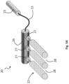
- the elongated portions 22 depart from a connecting body 26 with which they are in fluid communication.
- the connecting body 26 has the function to bring together the elongated portions 22 so as to facilitate the handling and the positioning of the elongated portions 22 inside the wearable protection device 10.
- the connecting body 26 might be a connecting pipe.
- the connecting pipe is made with a rigid material, for example it can be a metal pipe.
- the connecting pipe 26 can be connected to the inflation means 12 by means of a connecting duct 13 (see figure 5A ).
- the connecting pipe 26 is preferably provided with one or more outlets 27 designed to be connected to corresponding inlets of the elongated portions 22.
- the connecting body 26 can coincide with the inflation means 12.
- the inflation means 12 will be provided preferably with at least as many outlets as the number of the elongated portions 22.
- the inflation means can comprise two or more canisters, each canister being designed to inflate a different elongated portion of the inflatable member.
- the connecting body 26 can be a portion of the inflatable member 20 as shown in figures 4 and 5 .
- the connecting body 26 can be an inflatable portion of the inflatable member 20.
- the connecting body 26 might consist in a non-inflatable portion of the inflatable member 20, like a connecting duct connecting two different portions of the inflatable member, for example a duct connecting the front portion and the rear portion of the inflatable member.
- connecting body 26 is an inflatable portion of the inflatable member 20
- the connecting body 26 might be positioned around the neck of the wearer and can be superimposed over the top portion of the trunk, so that the various elongated portions 22 can extend, starting from the connecting body 26, over the shoulders, the back and the chest of the user (see figures 1-3 ).
- different arrangements of connecting body 26 and elongated portions 22 are possible in order to meet other specific needs.
- the inflation means 12 are connected to the connecting body 26, so that the inflation fluid is able to flow inside the connecting body 26 before reaching the elongated portions 22. In this way, a faster inflation of the inflatable member 20 can be obtained. At the same time, it is also possible to introduce the inflation fluid inside the inflatable member 20 with a high pressure. Also in this case the inflation means 12 can contain two or more canisters, each canister being designed for example to inflate a different portion of the inflatable member.
- At least one part of the at least two elongated portions 22 of the inflatable member 20 is enwrapped by at least one constraint 24.
- the function of the constraint 24 is to limit the expansion of the at least two elongated portions 22 when the inflatable member 20 moves from the rest condition to the active configuration. Therefore, thanks to the provision of the constraint 24, it is possible to control the shape of the inflatable member 20 once it is inflated without being forced to provide it with internal tethers.
- to limit the expansion is to be intended that a difference in volume between a free portion and a portion enwrapped by the constraint of the inflatable member can be detected when the internal pressure is above 0.2 bar.
- the constraint 24 is designed to enwrap only the elongated portions 22 of the inflatable member 20, without interfering with the expansion of the connecting body 26. In other words, advantageously, the constraint 24 does not fully enwrap the whole inflatable member 20.
- Parts of at least two adjacent elongated portions 22 of the inflatable member 20 are enwrapped by said at least one constraint 24.
- the adjacent elongated portions 22 advantageously are positioned in close proximity, not necessarily in contact, to each other.
- the elongated portions 22 are preferably aligned and transversally spaced apart to each other, so that air flow passages 28 can be defined between the portions 22.
- airflow passages 28 allow to improve the breathability and the comfort of the wearable protection device 10.
- the elongated portions 22 are preferably aligned and transversally connected by means of a connecting layer 30 provided between facing surfaces of the portions 22.
- the connecting layer 30 defines a non-inflatable zone of the inflatable member 20.
- the connecting layer 30 can be made of the same material forming the inflatable member 20.
- the connecting layer 30 can be made with a breathable fabric so as to provide breathable zones between two adjacent elongated portions 22.
- the function of the connecting layer 30 is to guarantee the alignment of the elongated portions 22 even in the inflated condition of the inflatable member 20.
- the constraint 24 can consist of a strip disposed transversally to the elongated portion 22.
- the strip form, without partition walls, is not according to the present claims.
- the constraint 24 is a strip disposed transversally to at least two adjacent elongated portions 22 to be connected.
- each elongated portion 22 can be connected to different elongated portions 22 by means of different constraint 24.
- a same elongated portion 22 can be connected to a first adjacent elongated portion by means of a first constraint 24 and to a second adjacent elongated portion by means of a second constraint 24.
- the elongated portions 22 arranged above the shoulders or the back of the user can be enwrapped by first constraints 24 and the elongated portions 22 arranged above the chest can be enwrapped by second constraints 24, different than the first constraints.
- this strip can be made of fabric or polymeric material.
- the strip 24 can be made of flexible material and, in some specific embodiment, it can also be provided with a limited elasticity.
- the constraint 24 consists of a casing acting as a partial cover for the adjacent elongated portions to be connected.
- the casing 24 fully covers the elongated portions 22 to be connected.
- the casing 24 can be made with a material having a controlled pliability in order to allow the elongated portions to better adapt to the body of the user, without impairing its retaining function.
- the casing 24 can be made with a breathable material, for example a mesh material or a breathable fabric.
- the casing 24 allows to also obtain, if needed, a planar configuration, namely a configuration having a thickness substantially uniform, of the elongated portions 22 when they are in the inflated condition.
- a planar configuration namely a configuration having a thickness substantially uniform
- the provision of the casing 24 allows to set a specific thickness of the elongated portions 22 in the inflated condition, for example 5-6 cm.
- Such a configuration is particularly useful because, in order to provide a uniform protection to the user, it is not needed to place a further protection element, like a plate, a back protector or a chest protector, on top of the elongated portions 22.
- the casing 24 is helpful in distributing the impact forces acting on the inflatable member 20 on a larger surface, by avoiding that the impact forces act locally and directly on the elongated portions 22.
- the inflatable member provided with the casing 24 is thus able to sustain increased external pressure without needing to be combined with an additional rigid or semirigid protector.
- the casing 24 can also be used advantageously when the elongated portions 22 are placed below a further protection element (not shown in the enclosed figures).
- a further protection element not shown in the enclosed figures.
- a flexible casing 24 advantageously permits the elongated portions 22 of the inflatable member to better adapt to the user's body when they are in the inflated status.
- the elongated portions 22 are allowed to also assume a bent configuration if needed.
- the strip configuration of the constraint 24 can be used to connect elongated portions 22 which are also connected by means of the connecting layer 30.
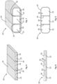
- the connecting layer 30 is preferably provided with a slit 32 suitable for being engaged by the constraint 24 (see figure 10-13 ).
- the strip configuration of the constraint 24 can also be used to connect together three elongated portions 22: a middle elongated portion 22a and two side adjacent elongated portions 22b (see figures 10-13 ).
- Such a configuration can be advantageously used when the area to be protected by the inflatable member 20 is greater.
- the middle elongated portion 22a is connected to each of the side adjacent elongated portions 22b by means of a separate constraint 24.
- the middle portion 22a is aligned and partially superimposed over the side adjacent portions 22b.
- the connecting layer 30 is made with a breathable material, air flow passages are still provided between the middle portion 22a and the side adjacent portions 22b of the inflatable member 20, without affecting the protection offered to the user.
- the elongated portions can assume a configuration wherein the middle portions 22a are interposed and in contact with the side portions 22b.
- the connecting layers 30 can be sandwiched between facing surfaces of the elongated portions 22a, 22b.
- the expansion of the elongated portions 22a, 22b is stopped when the volume defined by the constraint 24 is fully occupied.
- the inflatable member 20 preferably comprises a plurality of constraints 24 positioned in a spaced-apart relation to each other. In this way, similarly to the casing configuration of the constraint 24, the expansion of the elongated portions can be limited and controlled along their entire length.
- the provision of the constraints 24 allows the elongated portions 22, being the latter independent to each other, to better adapt to the user's body. For example, if the elongated portions 22 are disposed over a substantially planar surface, like for example the back of the user, the constraints 24 will be able to keep the portions 22, when they are inflated, in a substantially planar configuration. At the same time, if the elongated portions are disposed over a curved surface, for example over the shoulders or the sides of the user, the constraints 24 will be able to allow a bending of the elongated portions 22 so that the latter can adapt to the underlying surface.
- the casing configuration of the constraint 24 connects elongated portions 22 which are spaced apart to each other.
- the casing 24 is provided with partition walls 34 designed to define inside the casing 24 internal chambers 36, each chamber 36 housing one of the elongated portions 22 connected by the casing 24.
- the provision of the partition walls 34 helps the elongated portions 22 to stay aligned both in rest configuration and active configuration. Moreover, the partition walls 34 advantageously limit the expansion of the casing 24, so as to guarantee that the latter controls the expansion of the elongated portions 22, once they are inflated (see figures 7 and 9 ).
- the elongated portions 22 in the rest configuration can be arranged at least partially folded inside the internal chambers 36. In alternative embodiments, not shown in the figures, the elongated portions can be arranged at least partially rolled up inside the internal chambers 36.
- the expansion of the inflatable member 20 is controlled by means of the constraint 24, without the need of internal tethers inside the inflatable member 20.
- the inflatable member 20 thanks to the provision of the constraint 24 is able to better adapt to the user's body.
- the constraint 24 permits that the portions 22 assume a substantially planar configuration also in the inflated status, so as to offer an improved protection to the user without affecting the comfort and reducing the risk that the user's body might be compressed during the inflation of the inflatable member 20.
- the constraint 24 permits the elongated portions 22 to bend so as to better adapt to the user's body to protect.
- the provision of elongated portions spaced apart to each other allow to create airflow passages through the inflatable member, so as to improve the comfort and the breathability of the wearable protection device without affecting the protection offered thereof.
- the constraint 24 permits not only to control the final shape of the inflatable member, but also to limit the internal volume, and therefore to increase the internal pressure thereof.
- the constraint 24 in the form of the casing provided with internal partition walls is helpful in distributing on a larger surface the impact forces acting on the inflatable member 20, in particular on the elongated portions 22, so as to permit to sustain increased external pressure without needing to be combined with rigid or semirigid protections.
- both “sewed airbags” and “OPW airbags” can be used in combination with the constraint 24, without needing specific adjustments.
- the inflatable member 20 is thus manufactured in both cases at competitive costs, since it does not require to be provided with internal tethers or to be coated with additional layers to control its fluid retention.
Landscapes
- Engineering & Computer Science (AREA)
- Textile Engineering (AREA)
- Health & Medical Sciences (AREA)
- General Health & Medical Sciences (AREA)
- Physical Education & Sports Medicine (AREA)
- Professional, Industrial, Or Sporting Protective Garments (AREA)
- Electronic Switches (AREA)
- Connector Housings Or Holding Contact Members (AREA)
Claims (10)
- Tragbare Schutzvorrichtung (10), die mindestens ein aufblasbares Element (20) umfasst, das geeignet ist, sich zwischen einer Ruhekonfiguration, in der es sich in einem entleerten Zustand befindet, und einer aktiven Konfiguration, in der es sich in einem aufgeblasenen Zustand befindet, zu bewegen, wobei das mindestens eine aufblasbare Element (20) mindestens zwei längliche Abschnitte (22; 22a, 22b) umfasst, die von einem Verbindungskörper (26) ausgehen; wobei die mindestens zwei länglichen Abschnitte (22; 22a, 22b) so ausgelegt sind, dass sie benachbart zueinander positioniert sind und in Fluidverbindung mit dem Verbindungskörper (26) stehen;wobei Teile der mindestens zwei länglichen Abschnitte (22; 22a, 22b) von mindestens einer Begrenzung (24) umhüllt sind, die dazu ausgelegt ist, die Ausdehnung der mindestens zwei länglichen Abschnitte (22; 22a, 22b) zu begrenzen, wenn das aufblasbare Element (20) in die aktive Konfiguration übergeht, wobei die mindestens eine Begrenzung (24) aus einer Hülle besteht, die als eine Teilabdeckung für die mindestens zwei benachbarten länglichen Abschnitte (22; 22a, 22b) dient und die mindestens zwei benachbarten länglichen Abschnitte (22; 22a, 22b), die voneinander beabstandet sind, verbindet,dadurch gekennzeichnet, dassdie Hülle mit Trennwänden (34) versehen ist, um im Inneren der Hülle (24) Innenkammern (36) zu definieren; wobei jede Innenkammer (36) einen der mindestens zwei benachbarten länglichen Abschnitte (22; 22a, 22b) aufnimmt, die durch die Hülle (24) verbunden sind; wobei die mindestens zwei benachbarten länglichen Abschnitte (22; 22a, 22b) in der Ruhekonfiguration mindestens teilweise gefaltet oder aufgerollt im Inneren der Innenkammern (36) angeordnet sind.
- Tragbare Schutzvorrichtung (10) gemäß Anspruch 1, dadurch gekennzeichnet, dass die mindestens zwei benachbarten länglichen Abschnitte (22; 22a, 22b) ausgerichtet und quer zueinander beabstandet sind, sodass Luftdurchlasswege (28) zwischen den mindestens zwei benachbarten länglichen Abschnitten (22; 22a, 22b) definiert sind.
- Tragbare Schutzvorrichtung (10) gemäß Anspruch 1, dadurch gekennzeichnet, dass der Verbindungskörper (26) ein aufblasbarer Abschnitt des aufblasbaren Elements (20) ist.
- Tragbare Schutzvorrichtung (10) gemäß Anspruch 1, dadurch gekennzeichnet, dass der Verbindungskörper (26) ein nicht aufblasbarer Abschnitt des aufblasbaren Elements (20) ist.
- Tragbare Schutzvorrichtung (10) gemäß Anspruch 1, dadurch gekennzeichnet, dass der Verbindungskörper (26) ein Verbindungsrohr ist, das vorzugsweise aus einem starren Material hergestellt ist.
- Tragbare Schutzvorrichtung (10) gemäß Anspruch 5, dadurch gekennzeichnet, dass sie Aufblaseinrichtungen (12) in fluider Verbindung mit dem aufblasbaren Element (20) umfasst; wobei der Verbindungskörper (26) mit den Aufblaseinrichtungen (12) zusammenfällt.
- Tragbare Schutzvorrichtung (10) gemäß Anspruch 1, dadurch gekennzeichnet, dass sie Aufblaseinrichtungen (12) in fluider Verbindung mit dem aufblasbaren Element (20) und den mindestens zwei länglichen Abschnitten (22) umfasst; wobei die Aufblaseinrichtungen (12) zwei oder mehr Behälter umfassen, wobei jeder Behälter zum Aufblasen eines anderen länglichen Abschnitts (22) des aufblasbaren Elements (20) geeignet ist.
- Tragbare Schutzvorrichtung (10) gemäß Anspruch 1, dadurch gekennzeichnet, dass das mindestens eine aufblasbare Element (20) eine Vielzahl von länglichen Abschnitten (22; 22a, 22b) umfasst, die so gestaltet sind, dass sie benachbart zueinander positioniert sind; wobei die Vielzahl von länglichen Abschnitten (22; 22a, 22b), sobald sie aufgeblasen sind, einen Polsterkörper bilden, der aus einer Vielzahl von im Wesentlichen zylindrischen Polsterelementen besteht, die eng beieinander liegen.
- Tragbare Schutzvorrichtung (10) gemäß Anspruch 1, dadurch gekennzeichnet, dass die Hülle (24) aus einem atmungsaktiven Material hergestellt ist.
- Tragbare Schutzvorrichtung (10) gemäß Anspruch 9, dadurch gekennzeichnet, dass das atmungsaktive Material ein Netzmaterial oder ein atmungsaktiver Stoff ist.
Priority Applications (1)
| Application Number | Priority Date | Filing Date | Title |
|---|---|---|---|
| EP25182680.6A EP4591745A3 (de) | 2020-06-26 | 2021-06-23 | Tragbare schutzvorrichtung |
Applications Claiming Priority (2)
| Application Number | Priority Date | Filing Date | Title |
|---|---|---|---|
| IT102020000015454A IT202000015454A1 (it) | 2020-06-26 | 2020-06-26 | Dispositivo di protezione indossabile |
| PCT/EP2021/067142 WO2021260002A1 (en) | 2020-06-26 | 2021-06-23 | Wearable protection device |
Related Child Applications (1)
| Application Number | Title | Priority Date | Filing Date |
|---|---|---|---|
| EP25182680.6A Division EP4591745A3 (de) | 2020-06-26 | 2021-06-23 | Tragbare schutzvorrichtung |
Publications (2)
| Publication Number | Publication Date |
|---|---|
| EP4171302A1 EP4171302A1 (de) | 2023-05-03 |
| EP4171302B1 true EP4171302B1 (de) | 2025-06-18 |
Family
ID=72266755
Family Applications (2)
| Application Number | Title | Priority Date | Filing Date |
|---|---|---|---|
| EP25182680.6A Pending EP4591745A3 (de) | 2020-06-26 | 2021-06-23 | Tragbare schutzvorrichtung |
| EP21735674.0A Active EP4171302B1 (de) | 2020-06-26 | 2021-06-23 | Tragbares schutzvorrichtung |
Family Applications Before (1)
| Application Number | Title | Priority Date | Filing Date |
|---|---|---|---|
| EP25182680.6A Pending EP4591745A3 (de) | 2020-06-26 | 2021-06-23 | Tragbare schutzvorrichtung |
Country Status (8)
| Country | Link |
|---|---|
| US (1) | US12220008B2 (de) |
| EP (2) | EP4591745A3 (de) |
| JP (1) | JP7713974B2 (de) |
| KR (1) | KR102924308B1 (de) |
| CN (1) | CN116033844A (de) |
| ES (1) | ES3038280T3 (de) |
| IT (1) | IT202000015454A1 (de) |
| WO (1) | WO2021260002A1 (de) |
Families Citing this family (10)
| Publication number | Priority date | Publication date | Assignee | Title |
|---|---|---|---|---|
| IT201900016538A1 (it) * | 2019-09-17 | 2021-03-17 | Dainese Spa | Dispositivo di protezione e uso di detto dispositivo di protezione |
| ES2976045T3 (es) | 2019-12-13 | 2024-07-22 | Dainese Spa | Dispositivo de protección y procedimiento para fabricar dicho dispositivo de protección |
| IT202000015454A1 (it) * | 2020-06-26 | 2021-12-26 | Alpinestars Res Spa | Dispositivo di protezione indossabile |
| IT202000031358A1 (it) * | 2020-12-18 | 2022-06-18 | Alpinestars Res Spa | Dispositivo di protezione indossabile |
| IT202200010424A1 (it) * | 2022-05-19 | 2023-11-19 | D Air Lab S R L | Dispositivo di protezione personale |
| CN117502744A (zh) * | 2023-11-15 | 2024-02-06 | 杉杉品牌运营股份有限公司 | 一种可机洗的纯毛西服套装 |
| WO2025126114A1 (en) * | 2023-12-13 | 2025-06-19 | Armastec Pte. Ltd. | Exosuit |
| WO2025191464A1 (en) * | 2024-03-11 | 2025-09-18 | D-Air Lab S.r.l. | Wearable protective device and protective garment that includes the protective device |
| EP4640096A1 (de) | 2024-04-23 | 2025-10-29 | D-Air Lab S.r.l. | Schutzvorrichtung und verfahren zu ihrer herstellung |
| EP4640095A1 (de) | 2024-04-23 | 2025-10-29 | D-Air Lab S.r.l. | Schutzvorrichtung und verfahren zu ihrer herstellung |
Citations (9)
| Publication number | Priority date | Publication date | Assignee | Title |
|---|---|---|---|---|
| WO2010067393A1 (en) | 2008-12-09 | 2010-06-17 | Dainese S.P.A. | Protection device including an inflatable member |
| EP2621297B1 (de) | 2010-09-29 | 2017-08-09 | Hövding Sverige AB | Kopfschutz-airbag |
| WO2019048800A1 (fr) | 2017-09-11 | 2019-03-14 | Bouquillard De Milleret Xavier | Vêtement de protection à coussins gonflables amélioré |
| EP3498117A1 (de) | 2017-12-18 | 2019-06-19 | Dainese S.p.A. | Kleidungsstück zum schutz eines benutzers mit einem aufblasbaren element |
| CN110123064A (zh) | 2019-05-28 | 2019-08-16 | 翁文灏 | 一种超轻便携低成本的承压充气制品 |
| CN210169107U (zh) | 2019-03-20 | 2020-03-24 | 昆山正工模具有限公司 | 一种人体保护衣 |
| WO2020115158A1 (en) | 2018-12-05 | 2020-06-11 | Alpinestars Research Srl | Garment comprising an inflatable protection device |
| IT201900023958A1 (it) | 2019-12-13 | 2021-06-13 | D Air Lab S R L | Dispositivo di protezione e metodo per realizzare tale dispositivo di protezione |
| WO2021116931A1 (en) | 2019-12-13 | 2021-06-17 | D-Air Lab S.r.l. | Protective device and method for making said protective device |
Family Cites Families (13)
| Publication number | Priority date | Publication date | Assignee | Title |
|---|---|---|---|---|
| US4397046A (en) * | 1981-06-29 | 1983-08-09 | Lacoray S.A. | Protecting device especially for motor-cyclists |
| US6270386B1 (en) * | 1997-11-05 | 2001-08-07 | Avagear Inc. | Avalanche life-preserving jacket with airbag |
| EP2412257B1 (de) * | 2008-12-09 | 2014-01-29 | Dainese S.p.A. | Kleidungsstück, das zur Verbindung mit einer Vorrichtung für den persönlichen Schutz eines Benutzers ausgelegt ist |
| PT2437627E (pt) * | 2009-06-05 | 2014-03-26 | Alpinestars Res Srl | Sistema de almofadas de ar para motociclistas |
| IT1400264B1 (it) * | 2010-05-28 | 2013-05-24 | Freni Brembo Spa | Indumento protettivo con airbag |
| EA201891055A1 (ru) * | 2015-11-16 | 2018-11-30 | Кью30 Спортс Сайенс, Ллк | Устройства для защиты от травматического повреждения головного мозга |
| US9555311B1 (en) * | 2016-04-12 | 2017-01-31 | Ibtesam M. Y. Mustafa | Protective overgarment |
| CN109008010B (zh) | 2018-08-15 | 2021-10-22 | 苏州衣带保智能技术有限公司 | 一种人体安全保护气囊 |
| CN209359724U (zh) | 2018-09-25 | 2019-09-10 | 昆山正工模具有限公司 | 一种摔倒防护腰带用气囊结构 |
| CN210330003U (zh) | 2019-05-28 | 2020-04-17 | 翁文灏 | 一种超轻便携低成本的承压充气制品 |
| US11219262B2 (en) * | 2019-08-15 | 2022-01-11 | Honda Motor Co., Ltd. | System and method for providing safety assistance in vehicle |
| IT202000015454A1 (it) * | 2020-06-26 | 2021-12-26 | Alpinestars Res Spa | Dispositivo di protezione indossabile |
| CN111671174A (zh) | 2020-07-22 | 2020-09-18 | 福建锐翔体育科技股份有限公司 | 一种具有防风功能的轻薄春装及其制作方法 |
-
2020
- 2020-06-26 IT IT102020000015454A patent/IT202000015454A1/it unknown
-
2021
- 2021-06-23 CN CN202180051641.8A patent/CN116033844A/zh active Pending
- 2021-06-23 ES ES21735674T patent/ES3038280T3/es active Active
- 2021-06-23 EP EP25182680.6A patent/EP4591745A3/de active Pending
- 2021-06-23 WO PCT/EP2021/067142 patent/WO2021260002A1/en not_active Ceased
- 2021-06-23 JP JP2022580291A patent/JP7713974B2/ja active Active
- 2021-06-23 EP EP21735674.0A patent/EP4171302B1/de active Active
- 2021-06-23 US US18/003,097 patent/US12220008B2/en active Active
- 2021-07-16 KR KR1020237001430A patent/KR102924308B1/ko active Active
Patent Citations (9)
| Publication number | Priority date | Publication date | Assignee | Title |
|---|---|---|---|---|
| WO2010067393A1 (en) | 2008-12-09 | 2010-06-17 | Dainese S.P.A. | Protection device including an inflatable member |
| EP2621297B1 (de) | 2010-09-29 | 2017-08-09 | Hövding Sverige AB | Kopfschutz-airbag |
| WO2019048800A1 (fr) | 2017-09-11 | 2019-03-14 | Bouquillard De Milleret Xavier | Vêtement de protection à coussins gonflables amélioré |
| EP3498117A1 (de) | 2017-12-18 | 2019-06-19 | Dainese S.p.A. | Kleidungsstück zum schutz eines benutzers mit einem aufblasbaren element |
| WO2020115158A1 (en) | 2018-12-05 | 2020-06-11 | Alpinestars Research Srl | Garment comprising an inflatable protection device |
| CN210169107U (zh) | 2019-03-20 | 2020-03-24 | 昆山正工模具有限公司 | 一种人体保护衣 |
| CN110123064A (zh) | 2019-05-28 | 2019-08-16 | 翁文灏 | 一种超轻便携低成本的承压充气制品 |
| IT201900023958A1 (it) | 2019-12-13 | 2021-06-13 | D Air Lab S R L | Dispositivo di protezione e metodo per realizzare tale dispositivo di protezione |
| WO2021116931A1 (en) | 2019-12-13 | 2021-06-17 | D-Air Lab S.r.l. | Protective device and method for making said protective device |
Also Published As
| Publication number | Publication date |
|---|---|
| EP4591745A2 (de) | 2025-07-30 |
| EP4171302A1 (de) | 2023-05-03 |
| KR20240024764A (ko) | 2024-02-26 |
| JP2023531261A (ja) | 2023-07-21 |
| US12220008B2 (en) | 2025-02-11 |
| CN116033844A8 (zh) | 2023-05-26 |
| IT202000015454A1 (it) | 2021-12-26 |
| ES3038280T3 (en) | 2025-10-10 |
| WO2021260002A1 (en) | 2021-12-30 |
| EP4591745A3 (de) | 2025-10-15 |
| JP7713974B2 (ja) | 2025-07-28 |
| US20230240388A1 (en) | 2023-08-03 |
| KR102924308B1 (ko) | 2026-02-09 |
| CN116033844A (zh) | 2023-04-28 |
Similar Documents
| Publication | Publication Date | Title |
|---|---|---|
| US12220008B2 (en) | Wearable protection device | |
| JP7796788B2 (ja) | 着用可能なエアバッグ装置 | |
| KR102765198B1 (ko) | 팽창식 보호 디바이스를 포함하는 의복 | |
| EP4051041B1 (de) | Am körper tragbare schutzvorrichtung | |
| US20240049812A1 (en) | Wearable protection device | |
| JP2023505721A (ja) | 防護装置、及びこの防護装置の製造方法 | |
| EP3847917A1 (de) | Schutzvorrichtung | |
| WO2024095192A1 (en) | Inflatable protective device, wearable protective device comprising such an inflatable protective device and method for effectively deflating such an inflatable protective device after inflation | |
| WO2025191464A1 (en) | Wearable protective device and protective garment that includes the protective device |
Legal Events
| Date | Code | Title | Description |
|---|---|---|---|
| STAA | Information on the status of an ep patent application or granted ep patent |
Free format text: STATUS: UNKNOWN |
|
| STAA | Information on the status of an ep patent application or granted ep patent |
Free format text: STATUS: THE INTERNATIONAL PUBLICATION HAS BEEN MADE |
|
| PUAI | Public reference made under article 153(3) epc to a published international application that has entered the european phase |
Free format text: ORIGINAL CODE: 0009012 |
|
| STAA | Information on the status of an ep patent application or granted ep patent |
Free format text: STATUS: REQUEST FOR EXAMINATION WAS MADE |
|
| 17P | Request for examination filed |
Effective date: 20230117 |
|
| AK | Designated contracting states |
Kind code of ref document: A1 Designated state(s): AL AT BE BG CH CY CZ DE DK EE ES FI FR GB GR HR HU IE IS IT LI LT LU LV MC MK MT NL NO PL PT RO RS SE SI SK SM TR |
|
| DAV | Request for validation of the european patent (deleted) | ||
| DAX | Request for extension of the european patent (deleted) | ||
| STAA | Information on the status of an ep patent application or granted ep patent |
Free format text: STATUS: EXAMINATION IS IN PROGRESS |
|
| 17Q | First examination report despatched |
Effective date: 20240301 |
|
| TPAC | Observations filed by third parties |
Free format text: ORIGINAL CODE: EPIDOSNTIPA |
|
| GRAP | Despatch of communication of intention to grant a patent |
Free format text: ORIGINAL CODE: EPIDOSNIGR1 |
|
| STAA | Information on the status of an ep patent application or granted ep patent |
Free format text: STATUS: GRANT OF PATENT IS INTENDED |
|
| INTG | Intention to grant announced |
Effective date: 20250109 |
|
| GRAS | Grant fee paid |
Free format text: ORIGINAL CODE: EPIDOSNIGR3 |
|
| GRAA | (expected) grant |
Free format text: ORIGINAL CODE: 0009210 |
|
| STAA | Information on the status of an ep patent application or granted ep patent |
Free format text: STATUS: THE PATENT HAS BEEN GRANTED |
|
| RIN1 | Information on inventor provided before grant (corrected) |
Inventor name: GALASSINI, FILIPPO Inventor name: NARDO, LORENZO Inventor name: MAZZAROLO, GIOVANNI |
|
| AK | Designated contracting states |
Kind code of ref document: B1 Designated state(s): AL AT BE BG CH CY CZ DE DK EE ES FI FR GB GR HR HU IE IS IT LI LT LU LV MC MK MT NL NO PL PT RO RS SE SI SK SM TR |
|
| REG | Reference to a national code |
Ref country code: GB Ref legal event code: FG4D |
|
| REG | Reference to a national code |
Ref country code: CH Ref legal event code: EP |
|
| REG | Reference to a national code |
Ref country code: DE Ref legal event code: R096 Ref document number: 602021032465 Country of ref document: DE |
|
| PGFP | Annual fee paid to national office [announced via postgrant information from national office to epo] |
Ref country code: NL Payment date: 20250630 Year of fee payment: 5 |
|
| REG | Reference to a national code |
Ref country code: CH Ref legal event code: EP |
|
| REG | Reference to a national code |
Ref country code: IE Ref legal event code: FG4D |
|
| PGFP | Annual fee paid to national office [announced via postgrant information from national office to epo] |
Ref country code: AT Payment date: 20250721 Year of fee payment: 5 |
|
| P01 | Opt-out of the competence of the unified patent court (upc) registered |
Free format text: CASE NUMBER: APP_31830/2025 Effective date: 20250702 |
|
| REG | Reference to a national code |
Ref country code: NL Ref legal event code: FP |
|
| PG25 | Lapsed in a contracting state [announced via postgrant information from national office to epo] |
Ref country code: FI Free format text: LAPSE BECAUSE OF FAILURE TO SUBMIT A TRANSLATION OF THE DESCRIPTION OR TO PAY THE FEE WITHIN THE PRESCRIBED TIME-LIMIT Effective date: 20250618 |
|
| PGFP | Annual fee paid to national office [announced via postgrant information from national office to epo] |
Ref country code: ES Payment date: 20250701 Year of fee payment: 5 |
|
| PGFP | Annual fee paid to national office [announced via postgrant information from national office to epo] |
Ref country code: DE Payment date: 20250702 Year of fee payment: 5 |
|
| REG | Reference to a national code |
Ref country code: LT Ref legal event code: MG9D Ref country code: ES Ref legal event code: FG2A Ref document number: 3038280 Country of ref document: ES Kind code of ref document: T3 Effective date: 20251010 |
|
| PG25 | Lapsed in a contracting state [announced via postgrant information from national office to epo] |
Ref country code: NO Free format text: LAPSE BECAUSE OF FAILURE TO SUBMIT A TRANSLATION OF THE DESCRIPTION OR TO PAY THE FEE WITHIN THE PRESCRIBED TIME-LIMIT Effective date: 20250918 Ref country code: GR Free format text: LAPSE BECAUSE OF FAILURE TO SUBMIT A TRANSLATION OF THE DESCRIPTION OR TO PAY THE FEE WITHIN THE PRESCRIBED TIME-LIMIT Effective date: 20250919 |
|
| PGFP | Annual fee paid to national office [announced via postgrant information from national office to epo] |
Ref country code: TR Payment date: 20250812 Year of fee payment: 5 |
|
| PG25 | Lapsed in a contracting state [announced via postgrant information from national office to epo] |
Ref country code: BG Free format text: LAPSE BECAUSE OF FAILURE TO SUBMIT A TRANSLATION OF THE DESCRIPTION OR TO PAY THE FEE WITHIN THE PRESCRIBED TIME-LIMIT Effective date: 20250618 |
|
| PGFP | Annual fee paid to national office [announced via postgrant information from national office to epo] |
Ref country code: GB Payment date: 20250911 Year of fee payment: 5 |
|
| PG25 | Lapsed in a contracting state [announced via postgrant information from national office to epo] |
Ref country code: HR Free format text: LAPSE BECAUSE OF FAILURE TO SUBMIT A TRANSLATION OF THE DESCRIPTION OR TO PAY THE FEE WITHIN THE PRESCRIBED TIME-LIMIT Effective date: 20250618 |
|
| PGFP | Annual fee paid to national office [announced via postgrant information from national office to epo] |
Ref country code: FR Payment date: 20250709 Year of fee payment: 5 |
|
| PG25 | Lapsed in a contracting state [announced via postgrant information from national office to epo] |
Ref country code: RS Free format text: LAPSE BECAUSE OF FAILURE TO SUBMIT A TRANSLATION OF THE DESCRIPTION OR TO PAY THE FEE WITHIN THE PRESCRIBED TIME-LIMIT Effective date: 20250918 |
|
| PG25 | Lapsed in a contracting state [announced via postgrant information from national office to epo] |
Ref country code: LV Free format text: LAPSE BECAUSE OF FAILURE TO SUBMIT A TRANSLATION OF THE DESCRIPTION OR TO PAY THE FEE WITHIN THE PRESCRIBED TIME-LIMIT Effective date: 20250618 |
|
| PG25 | Lapsed in a contracting state [announced via postgrant information from national office to epo] |
Ref country code: PT Free format text: LAPSE BECAUSE OF FAILURE TO SUBMIT A TRANSLATION OF THE DESCRIPTION OR TO PAY THE FEE WITHIN THE PRESCRIBED TIME-LIMIT Effective date: 20251020 |
|
| REG | Reference to a national code |
Ref country code: AT Ref legal event code: MK05 Ref document number: 1803378 Country of ref document: AT Kind code of ref document: T Effective date: 20250618 |
|
| PG25 | Lapsed in a contracting state [announced via postgrant information from national office to epo] |
Ref country code: IS Free format text: LAPSE BECAUSE OF FAILURE TO SUBMIT A TRANSLATION OF THE DESCRIPTION OR TO PAY THE FEE WITHIN THE PRESCRIBED TIME-LIMIT Effective date: 20251018 |
|
| PG25 | Lapsed in a contracting state [announced via postgrant information from national office to epo] |
Ref country code: SM Free format text: LAPSE BECAUSE OF FAILURE TO SUBMIT A TRANSLATION OF THE DESCRIPTION OR TO PAY THE FEE WITHIN THE PRESCRIBED TIME-LIMIT Effective date: 20250618 Ref country code: AT Free format text: LAPSE BECAUSE OF FAILURE TO SUBMIT A TRANSLATION OF THE DESCRIPTION OR TO PAY THE FEE WITHIN THE PRESCRIBED TIME-LIMIT Effective date: 20250618 |
|
| PG25 | Lapsed in a contracting state [announced via postgrant information from national office to epo] |
Ref country code: CZ Free format text: LAPSE BECAUSE OF FAILURE TO SUBMIT A TRANSLATION OF THE DESCRIPTION OR TO PAY THE FEE WITHIN THE PRESCRIBED TIME-LIMIT Effective date: 20250618 |
|
| PG25 | Lapsed in a contracting state [announced via postgrant information from national office to epo] |
Ref country code: PL Free format text: LAPSE BECAUSE OF FAILURE TO SUBMIT A TRANSLATION OF THE DESCRIPTION OR TO PAY THE FEE WITHIN THE PRESCRIBED TIME-LIMIT Effective date: 20250618 |
|
| PG25 | Lapsed in a contracting state [announced via postgrant information from national office to epo] |
Ref country code: EE Free format text: LAPSE BECAUSE OF FAILURE TO SUBMIT A TRANSLATION OF THE DESCRIPTION OR TO PAY THE FEE WITHIN THE PRESCRIBED TIME-LIMIT Effective date: 20250618 |
|
| PG25 | Lapsed in a contracting state [announced via postgrant information from national office to epo] |
Ref country code: SK Free format text: LAPSE BECAUSE OF FAILURE TO SUBMIT A TRANSLATION OF THE DESCRIPTION OR TO PAY THE FEE WITHIN THE PRESCRIBED TIME-LIMIT Effective date: 20250618 |
|
| REG | Reference to a national code |
Ref country code: CH Ref legal event code: H13 Free format text: ST27 STATUS EVENT CODE: U-0-0-H10-H13 (AS PROVIDED BY THE NATIONAL OFFICE) Effective date: 20260127 |
|
| PG25 | Lapsed in a contracting state [announced via postgrant information from national office to epo] |
Ref country code: LU Free format text: LAPSE BECAUSE OF NON-PAYMENT OF DUE FEES Effective date: 20250623 |
|
| REG | Reference to a national code |
Ref country code: BE Ref legal event code: MM Effective date: 20250630 |
|
| PG25 | Lapsed in a contracting state [announced via postgrant information from national office to epo] |
Ref country code: RO Free format text: LAPSE BECAUSE OF FAILURE TO SUBMIT A TRANSLATION OF THE DESCRIPTION OR TO PAY THE FEE WITHIN THE PRESCRIBED TIME-LIMIT Effective date: 20250618 |
|
| REG | Reference to a national code |
Ref country code: DE Ref legal event code: R026 Ref document number: 602021032465 Country of ref document: DE |
|
| PLBI | Opposition filed |
Free format text: ORIGINAL CODE: 0009260 |
|
| PG25 | Lapsed in a contracting state [announced via postgrant information from national office to epo] |
Ref country code: MC Free format text: LAPSE BECAUSE OF FAILURE TO SUBMIT A TRANSLATION OF THE DESCRIPTION OR TO PAY THE FEE WITHIN THE PRESCRIBED TIME-LIMIT Effective date: 20250618 |
|
| PLAX | Notice of opposition and request to file observation + time limit sent |
Free format text: ORIGINAL CODE: EPIDOSNOBS2 |
|
| REG | Reference to a national code |
Ref country code: CH Ref legal event code: L10 Free format text: ST27 STATUS EVENT CODE: U-0-0-L10-L00 (AS PROVIDED BY THE NATIONAL OFFICE) Effective date: 20260402 |
|
| PG25 | Lapsed in a contracting state [announced via postgrant information from national office to epo] |
Ref country code: IE Free format text: LAPSE BECAUSE OF NON-PAYMENT OF DUE FEES Effective date: 20250623 Ref country code: DK Free format text: LAPSE BECAUSE OF FAILURE TO SUBMIT A TRANSLATION OF THE DESCRIPTION OR TO PAY THE FEE WITHIN THE PRESCRIBED TIME-LIMIT Effective date: 20250618 |
|
| PG25 | Lapsed in a contracting state [announced via postgrant information from national office to epo] |
Ref country code: IT Free format text: LAPSE BECAUSE OF NON-PAYMENT OF DUE FEES Effective date: 20250623 Ref country code: BE Free format text: LAPSE BECAUSE OF NON-PAYMENT OF DUE FEES Effective date: 20250630 |
|
| PG25 | Lapsed in a contracting state [announced via postgrant information from national office to epo] |
Ref country code: CH Free format text: LAPSE BECAUSE OF NON-PAYMENT OF DUE FEES Effective date: 20250630 |
|
| 26 | Opposition filed |
Opponent name: D-AIR LAB S.R.L. Effective date: 20260318 |