EP4171062A1 - Vehicle speaker arrangement - Google Patents
Vehicle speaker arrangement Download PDFInfo
- Publication number
- EP4171062A1 EP4171062A1 EP22211647.7A EP22211647A EP4171062A1 EP 4171062 A1 EP4171062 A1 EP 4171062A1 EP 22211647 A EP22211647 A EP 22211647A EP 4171062 A1 EP4171062 A1 EP 4171062A1
- Authority
- EP
- European Patent Office
- Prior art keywords
- vehicle
- duct
- speaker
- audio system
- door
- Prior art date
- Legal status (The legal status is an assumption and is not a legal conclusion. Google has not performed a legal analysis and makes no representation as to the accuracy of the status listed.)
- Pending
Links
Images



Classifications
-
- H—ELECTRICITY
- H04—ELECTRIC COMMUNICATION TECHNIQUE
- H04R—LOUDSPEAKERS, MICROPHONES, GRAMOPHONE PICK-UPS OR LIKE ACOUSTIC ELECTROMECHANICAL TRANSDUCERS; ELECTRIC HEARING AIDS; PUBLIC ADDRESS SYSTEMS
- H04R1/00—Details of transducers, loudspeakers or microphones
- H04R1/20—Arrangements for obtaining desired frequency or directional characteristics
- H04R1/22—Arrangements for obtaining desired frequency or directional characteristics for obtaining desired frequency characteristic only
- H04R1/28—Transducer mountings or enclosures modified by provision of mechanical or acoustic impedances, e.g. resonator, damping means
- H04R1/2807—Enclosures comprising vibrating or resonating arrangements
- H04R1/2838—Enclosures comprising vibrating or resonating arrangements of the bandpass type
- H04R1/2846—Vents, i.e. ports, e.g. shape thereof or tuning thereof with damping material
- H04R1/2849—Vents, i.e. ports, e.g. shape thereof or tuning thereof with damping material for loudspeaker transducers
-
- H—ELECTRICITY
- H04—ELECTRIC COMMUNICATION TECHNIQUE
- H04R—LOUDSPEAKERS, MICROPHONES, GRAMOPHONE PICK-UPS OR LIKE ACOUSTIC ELECTROMECHANICAL TRANSDUCERS; ELECTRIC HEARING AIDS; PUBLIC ADDRESS SYSTEMS
- H04R1/00—Details of transducers, loudspeakers or microphones
- H04R1/02—Casings; Cabinets ; Supports therefor; Mountings therein
- H04R1/026—Supports for loudspeaker casings
-
- H—ELECTRICITY
- H04—ELECTRIC COMMUNICATION TECHNIQUE
- H04R—LOUDSPEAKERS, MICROPHONES, GRAMOPHONE PICK-UPS OR LIKE ACOUSTIC ELECTROMECHANICAL TRANSDUCERS; ELECTRIC HEARING AIDS; PUBLIC ADDRESS SYSTEMS
- H04R1/00—Details of transducers, loudspeakers or microphones
- H04R1/20—Arrangements for obtaining desired frequency or directional characteristics
- H04R1/22—Arrangements for obtaining desired frequency or directional characteristics for obtaining desired frequency characteristic only
-
- H—ELECTRICITY
- H04—ELECTRIC COMMUNICATION TECHNIQUE
- H04R—LOUDSPEAKERS, MICROPHONES, GRAMOPHONE PICK-UPS OR LIKE ACOUSTIC ELECTROMECHANICAL TRANSDUCERS; ELECTRIC HEARING AIDS; PUBLIC ADDRESS SYSTEMS
- H04R1/00—Details of transducers, loudspeakers or microphones
- H04R1/20—Arrangements for obtaining desired frequency or directional characteristics
- H04R1/22—Arrangements for obtaining desired frequency or directional characteristics for obtaining desired frequency characteristic only
- H04R1/28—Transducer mountings or enclosures modified by provision of mechanical or acoustic impedances, e.g. resonator, damping means
- H04R1/2869—Reduction of undesired resonances, i.e. standing waves within enclosure, or of undesired vibrations, i.e. of the enclosure itself
-
- H—ELECTRICITY
- H04—ELECTRIC COMMUNICATION TECHNIQUE
- H04R—LOUDSPEAKERS, MICROPHONES, GRAMOPHONE PICK-UPS OR LIKE ACOUSTIC ELECTROMECHANICAL TRANSDUCERS; ELECTRIC HEARING AIDS; PUBLIC ADDRESS SYSTEMS
- H04R2201/00—Details of transducers, loudspeakers or microphones covered by H04R1/00 but not provided for in any of its subgroups
- H04R2201/02—Details casings, cabinets or mounting therein for transducers covered by H04R1/02 but not provided for in any of its subgroups
- H04R2201/021—Transducers or their casings adapted for mounting in or to a wall or ceiling
-
- H—ELECTRICITY
- H04—ELECTRIC COMMUNICATION TECHNIQUE
- H04R—LOUDSPEAKERS, MICROPHONES, GRAMOPHONE PICK-UPS OR LIKE ACOUSTIC ELECTROMECHANICAL TRANSDUCERS; ELECTRIC HEARING AIDS; PUBLIC ADDRESS SYSTEMS
- H04R2499/00—Aspects covered by H04R or H04S not otherwise provided for in their subgroups
- H04R2499/10—General applications
- H04R2499/13—Acoustic transducers and sound field adaptation in vehicles
Definitions
- the present disclosure generally relates to loudspeakers systems having at least one bass-range, low frequency speaker. More particularly, the present disclosure relates to vehicles having a bass-range speaker.
- Loudspeakers for producing bass-range, low-frequency sound are utilized in vehicles audio systems.
- One example is European Patent No. EP1407934 by Harman Becker Automotive Systems GmbH.
- an audio system for a vehicle having a bass-range speaker mounted in a vehicle cavity.
- the speaker has a front side for producing an acoustic output in a passenger compartment of the vehicle.
- the vehicle cavity encloses a back side of the speaker.
- a duct having a first end is in fluid communication with the vehicle cavity and a second end is in fluid communication with the atmosphere outside the vehicle.
- the vehicle cavity is formed in a vehicle door.
- the duct extends from the forward side of the vehicle door across a hinge area between the vehicle door and a body structure of the vehicle.
- the second end of the duct is positioned adjacent an opening formed in a wheel well of the vehicle.
- the second end of the duct is positioned in the engine compartment of the vehicle.
- the second end of the duct is in fluid communication with a B-pillar of the vehicle.
- the B-pillar has an opening in fluid communication with the atmosphere outside the vehicle.
- At least a portion of the duct is contained in a grommet along the hinge area, and wherein the gromment also contains electrical wiring.
- the duct has a cross-sectional area being at least twenty-five percent of a cone area of the speaker.
- the speaker is fluidly sealed between the first end and the second end.
- At least a portion of the duct is flexible.
- an audio system for a vehicle having a speaker housing mounted in the vehicle.
- a bass-range speaker is mounted in the housing for producing low frequency acoustic output to a passenger compartment from a front side of the speaker.
- the housing encloses the back side of the speaker.
- a duct having a proximal end is fluidly sealed to the housing. The duct extends to a distal end in fluid communication with the atmosphere outside the vehicle.
- the speaker housing is not a sealed resonance volume, wherein the duct provides an infinite baffle with the atmosphere outside the vehicle.
- the speaker is mounted in a door of the vehicle.
- the duct extends from the forward side of the door across a hinge area between the vehicle door and a forward body structure.
- the distal end is fluidly connected to an opening in a forward body structure of the vehicle being open to the atmosphere.
- At least one of the proximal and distal ends of the duct is covered in an acoustic resistive material to minimize noise from the atmophere in the passenger compartment of the vehicle.
- the duct has a cross-sectional area being at least twenty-five percent of a cone area of the speaker.
- the duct is fluidly sealed between the first end and the second end of the duct.
- a method including mounting a speaker in a cavity in a vehicle.
- a duct is provided having a first end in fluid communication with the cavity and a second end in fluid communication with the atmosphere outside the vehicle.
- the duct is routed to extend across a hinge area between a vehicle door and a vehicle body structure.
- At least a portion of the duct is routed through a grommet along the hinge area. Electrical wiring is routed through the gromment adjacent the portion of the duct.
- the duct has a cross-sectional area being at least twenty-five percent of a cone area of the speaker.
- Figure 1 illustrates a vehicle 10 having a front door 12 connected to the A-pillar 14 of the vehicle 10 by a hinge along a forward side 16.
- the door 12 is framed by a roof support 18, a B-pillar 20 and a sill 22.
- an upper side 24 of the door seals with the roof support 18, a rear side 28 of the door seals and latches with the B-pillar 20 and a bottom side 30 seals with the sill 22.
- a loudspeaker 34 is installed in a cavity in the front door 12.
- the vehicle 10 may also have a rear door 42 connected to the B-pillar 20 of the vehicle.
- the rear door 42 may be connected by a hinge along the B-pillar 20, or may latch along the B-pillar 20 and slide longitudinally or open in another direction.
- the rear door 42 is framed by the roof support 18, a C-pillar 44 and the sill 22.
- an upper side 46 seals with the roof support 18, a rear side 48 seals and/or latches with the C-pillar 44 and a bottom side 50 seals with the sill 22.
- a loudspeaker 34 may be similarly installed in a cavity in the rear door 42.
- the vehicle includes an audio system having a bass-compatible speaker 34 installed in the doors 12, 42.
- the speaker 34 is installed in a cavity 54 below the windows 36.
- the bass-compatible speaker 34 is designed to at least emit sound in a portion of the bass-range in addition to emitting frequencies outside of the bass-range. It is difficult to have a large enough resonant volume in a cavity enclosed by the door underneath the windows because components such as window-lifting mechanisms, wiring, side airbags, locking devices and other vehicle components are located in this area. Therefore, speakers provided in doors without adequate resonant volume cavities may produce inadequate low-frequency output, excessive mechanical vibration and/or other undesirable effects such as buzz, squeak, and rattle. This can be a particular problem for loudspeakers that provide low-frequency sound, such as a bass-compatible speaker, which require a large resonant volume.
- a bass-compatible speaker may include a subwoofer, a traditional woofer or other bass speaker that operates in the bass-range.
- the bass-range is a low frequency range, which may be around 20 Hertz (Hz) to 400 Hz.
- subwoofers generally emit sound between 20 Hz and 200 Hz
- traditional woofers generally emit sound between 40 Hz and 400 Hz.
- the bass-range sound in the door-mounted speakers 34 is improved by providing a pathway so that the back side of the speaker is in fluid communication with the atmosphere outside of the passenger compartment 38 and/or outside the vehicle.
- the front side of the speaker refers to the sound-emitting side of the speaker and is generally in fluid communication with the passenger compartment 38 of the vehicle.
- the speakers 34 are in fluid communication with the atmosphere via a duct 60.
- the front speaker 34 is in fluid communication with the atmosphere via the duct 60 and an opening in the wheel well 62.
- the duct 60 may also be routed to be in fluid communication with the atmosphere via the engine compartment or anther suitable location.
- the back side of the speaker may be in fluid communication an additional cavity or cavities outside of the passenger compartment 38, but within the vehicle via the duct 60.
- the rear speaker 34 is in fluid communication with the atmosphere via the duct 60 and an opening in the B-pillar 20 along the underside 64 of the vehicle.
- the duct 60 may also be routed to be in fluid communication with the atmosphere via the sill, for sliding rear door applications, or another suitable location.
- the speaker When the back side of the speaker is in fluid communication with the atmosphere outside of the vehicle, the speaker is considered to have an infinite baffle.
- One benefit of having the back side of the speaker in fluid communication with the open atmosphere is that undesirable resonances in the speaker are reduced because sound waves emitted from the back side of the speaker do not interfere with sound waves emitted from the front side of the speaker.
- another benefit of the open environment, or infinite baffle is that strain in the diaphragm is reduced because the back side of the speaker vents to the outside atmosphere. As a result, the speaker open to the atmosphere outside the vehicle produces a higher sound pressure level (SPL) at low frequency ranges inside the vehicle.
- SPL sound pressure level
- Another benefit of having the back side of the speaker in fluid communication with the open atmosphere is that sealed speaker enclosures within the door can be eliminated. Removing sealed speaker enclosures reduces cost, complexity and weight. Even in designs where the volume of the door cavity itself provides a resonant volume, like in European Patent EP1407934 , door treatments that are required prove a sealed resonance volume can be eliminated. By not requiring the door components to provide a sealed cavity, manufacturability is increased, also providing cost and component savings.
- Figure 2 shows the interior 70 of the front side door 12 that faces the passenger compartment 38.
- the side door 12 has a speaker mounting cavity 54 or mounting location.
- the speaker housing 74 and speaker 34 are mounted to the interior 70 of the door with fasteners 78 at the speaker cavity 54.
- Figure 2 also illustrates the hinge area 88 when the vehicle door 12 is in a hinged open position.
- Figure 3 shows the interior 70 of the front side door 12 in more detail with the speaker removed.
- the speaker housing 74 has a receptacle 76 for receiving the speaker.
- An outlet aperture 80 is defined along a surface of the housing receptacle 76.
- the outlet aperture 80 may be positioned closer to the forward side 16 of the door 12.
- Figure 3 further illustrates the hinge area 88 in closer detail when the vehicle door 12 is in the hinged open position.
- the duct 60 may be flexible to accommodate movement required along the hinged opening 88 when the door 34 moves between hinged open and closed positions.
- Figure 4 further illustrates the speaker 34 and hinge area 88 in more detail when the vehicle door 12 is in the hinged open position.
- a duct 60 is coupled to the aperture 80 at a first end 66 and is routed toward the forward side 16 of the door 12.
- the duct 60 may be sealed to the aperture 80 with adhesive or sealed by any suitable method.
- the duct 60 may be formed as a single piece with the housing 74.
- the duct 60 is fluidly sealed between the first end 66 and second end 68 ( Figure 1 ) in order to prevent sound from the back side of the speaker from entering the passenger compartment and to be only in fluid communication with the atmosphere outside the vehicle without leaks that may cause vibrations or may diminish speaker performance and/or output.
- the duct 60 extends from the forward side 16 of the door 12 to the front body 82 of the vehicle 10.
- the duct 60 extends to an opening in the front vehicle body 82 that is open and in fluid communication with the atmosphere.
- the second end of the duct 60 may extend to an opening in the wheel well 62, as shown in Figure 1 .
- the opening in the wheel well 62 may be concealed, so that it is not easily visible from outside the vehicle.
- the duct 60 may be routed along the front of the vehicle to an opening in the engine compartment. By visually concealing the second end of the duct 60, the aesthetics and design characteristics of the vehicle are not affected.
- the duct 60 may be formed of flexible rubber hose or grommet material.
- the duct 60 is able to bend and extend across the hinge area 88 between the forward side 16 of the door 12 and the front body 82 of the vehicle as the door 12 opens and closes.
- Vehicles may have grommet or hose that extends from between the door and the body that contains electrical wiring for controlling door functions such as the electric window and locks.
- the duct 60 may include the wiring, or may be a separate hose.
- Figure 6 illustrates the speaker housing 74 removed from the vehicle door. As shown in Figure 6 , the speaker housing 74 is not a sealed resonance volume. The speaker housing 74 has a receptacle 76 for receiving the speaker 34 from the interior 70 of the vehicle. The speaker housing 74 may also have a exterior opening.
- the cross-sectional area 90 ( Fig. 3 ) of the duct 60 and outlet aperture 80 is generally at least twenty-five percent of the area of the speaker's cone 92 ( Fig. 2 ).
- the cross-sectional area 90 is at least generally twenty-five percent of the cone area 92, the acoustic resonance is minimized.
- a noise, vibration and harshness (NVH) hat and/or acoustic resistive material may be added to the outlet aperture 80 or at the second end of the duct 60 to provide noise isolation from the outside atmosphere while allowing fluid communication between the speakers 34 and the outside environment. Even with the back side of the speaker in fluid communication with the open environment outside of the vehicle, unwanted resonance is significantly reduced while outside noise is minimized or prevent from entering the vehicle via the acoustic resistive material. Accordingly, sound quality in the bass-range is improved due to the reduced mechanical vibration as well as the multi-directional emission of the bass-range.
- the vehicle 10 may also include a control unit that is in communication with each of the speakers 34.
- the audio control unit may manage bass and sound distribution that may be emitted outside of a vehicle via the duct 60, as described in International Patent Application No. PCT/US16/15393 by Harman International Industries, Inc. , the disclosure of which is incorporated by reference herein.
- the control unit may adjust the sound pressure level of the speakers 34 and/or redistribute bass-range emissions based on operation of the vehicle, such as the vehicle speed.
- Example 1 An audio system for a vehicle comprising: a bass-range speaker mounted in a vehicle cavity, the bass-range speaker having a front side for producing an acoustic output in a passenger compartment of the vehicle, wherein the vehicle cavity encloses a back side of the bass-range speaker; and a duct having a first end and a second end, the first end being in communication with the vehicle cavity and the second end being in fluid communication with the atmosphere outside the vehicle.
- Example 2 The audio system of example 1, wherein the vehicle cavity is formed in a vehicle door.
- Example 3 The audio system of example 2, wherein the duct extends from a forward side of the vehicle door across a hinge area between the vehicle door and a body structure of the vehicle.
- Example 4 The audio system of example 1, wherein the second end of the duct is positioned adjacent an opening formed in a wheel well of the vehicle.
- Example 5 The audio system of example 1, wherein the second end of the duct is positioned in an engine compartment of the vehicle.
- Example 6 The audio system of example 1, wherein the second end of the duct is in fluid communication with a B-pillar of the vehicle, wherein the B-pillar has an opening in fluid communication with the atmosphere outside the vehicle.
- Example 7 The audio system of example 3, wherein at least a portion of the duct is contained in a grommet along the hinge area, and wherein the grommet contains electrical wiring.
- Example 8 The audio system of example 1, wherein the duct has a cross-sectional area being at least twenty-five percent of a cone area of the speaker.
- Example 9 The audio system of example 1, wherein the bass-range speaker is fluidly sealed between the first end and the second end.
- Example 10 The audio system of example 1, wherein at least a portion of the duct is flexible.
- Example 11 An audio system for a vehicle comprising: a speaker housing mounted in the vehicle; a bass-range speaker mounted in the speaker housing for producing low frequency acoustic output from a front side of the bass-range speaker to a passenger compartment of the vehicle, the speaker housing enclosing a back side of the bass-range speaker; and a duct having a proximal end extending to a distal end, the proximal end being fluidly sealed in the speaker housing and the distal end being in fluid communication with the atmosphere outside the vehicle.
- Example 12 The audio system of example 11, wherein the speaker housing is not a sealed resonance volume.
- Example 13 The audio system of example 11, wherein the bass-range speaker is mounted in a door of the vehicle and the duct extends from a forward side of the door across a hinge area between the vehicle door and a forward body structure, wherein the distal end is fluidly connected to the forward body structure of the vehicle being open to the atmosphere.
- Example 14 The audio system of example 13, wherein at least one of the proximal end and the distal end of the duct is covered in an acoustic resistive material to minimize noise from the atmosphere in the passenger compartment of the vehicle.
- Example 15 The audio system of example 11, wherein the duct has a cross-sectional area being at least twenty-five percent of a cone area of the speaker.
- Example 16 The audio system of example 11, wherein the duct is fluidly sealed between the proximal end and the distal end.
- Example 17 A method for arranging an audio system in a vehicle comprising: mounting a speaker in a cavity in the vehicle; providing a duct having a first end in fluid communication with the cavity and a second end in fluid communication with the atmosphere outside the vehicle.
- Example 18 The method of example 17, further comprising routing the duct to extend across a hinge area between a vehicle door and a vehicle body structure.
- Example 19 The method of example 18, further comprising: routing at least a portion of the duct through a grommet along the hinge area; and routing electrical wiring through the grommet adjacent the portion of the duct.
- Example 20 The method of example 17, wherein the duct has a cross-sectional area being at least twenty-five percent of a cone area of the speaker.
Landscapes
- Physics & Mathematics (AREA)
- Engineering & Computer Science (AREA)
- Acoustics & Sound (AREA)
- Signal Processing (AREA)
- Health & Medical Sciences (AREA)
- Otolaryngology (AREA)
- Fittings On The Vehicle Exterior For Carrying Loads, And Devices For Holding Or Mounting Articles (AREA)
- Details Of Audible-Bandwidth Transducers (AREA)
Abstract
Description
- This application claims the benefit of
U.S. provisional application Serial No. 62/334,154 filed May 10, 2016 - The present disclosure generally relates to loudspeakers systems having at least one bass-range, low frequency speaker. More particularly, the present disclosure relates to vehicles having a bass-range speaker.
- Loudspeakers for producing bass-range, low-frequency sound are utilized in vehicles audio systems. One example is European Patent No.
EP1407934 by Harman Becker Automotive Systems GmbH. - According to at least one embodiment, an audio system for a vehicle is provided having a bass-range speaker mounted in a vehicle cavity. The speaker has a front side for producing an acoustic output in a passenger compartment of the vehicle. The vehicle cavity encloses a back side of the speaker. A duct having a first end is in fluid communication with the vehicle cavity and a second end is in fluid communication with the atmosphere outside the vehicle.
- According to a further embodiment, the vehicle cavity is formed in a vehicle door.
- According to another embodiment, the duct extends from the forward side of the vehicle door across a hinge area between the vehicle door and a body structure of the vehicle.
- According to still another embodiment, the second end of the duct is positioned adjacent an opening formed in a wheel well of the vehicle.
- According to another embodiment, the second end of the duct is positioned in the engine compartment of the vehicle.
- According to a further embodiment, the second end of the duct is in fluid communication with a B-pillar of the vehicle. The B-pillar has an opening in fluid communication with the atmosphere outside the vehicle.
- According to another embodiment, at least a portion of the duct is contained in a grommet along the hinge area, and wherein the gromment also contains electrical wiring.
- According to yet another embodiment, the duct has a cross-sectional area being at least twenty-five percent of a cone area of the speaker.
- According to another embodiment, the speaker is fluidly sealed between the first end and the second end.
- According to a further embodiment, at least a portion of the duct is flexible.
- According to at least one embodiment, an audio system for a vehicle is provided having a speaker housing mounted in the vehicle. A bass-range speaker is mounted in the housing for producing low frequency acoustic output to a passenger compartment from a front side of the speaker. The housing encloses the back side of the speaker. A duct having a proximal end is fluidly sealed to the housing. The duct extends to a distal end in fluid communication with the atmosphere outside the vehicle.
- According to another embodiment, the speaker housing is not a sealed resonance volume, wherein the duct provides an infinite baffle with the atmosphere outside the vehicle.
- According to still another embodiment, the speaker is mounted in a door of the vehicle. The duct extends from the forward side of the door across a hinge area between the vehicle door and a forward body structure. The distal end is fluidly connected to an opening in a forward body structure of the vehicle being open to the atmosphere.
- According to another embodiment, at least one of the proximal and distal ends of the duct is covered in an acoustic resistive material to minimize noise from the atmophere in the passenger compartment of the vehicle.
- According to a further embodiment, the duct has a cross-sectional area being at least twenty-five percent of a cone area of the speaker.
- According to another embodiment, the duct is fluidly sealed between the first end and the second end of the duct.
- According to at least one embodiment, a method is provided including mounting a speaker in a cavity in a vehicle. A duct is provided having a first end in fluid communication with the cavity and a second end in fluid communication with the atmosphere outside the vehicle.
- According to another embodiment, the duct is routed to extend across a hinge area between a vehicle door and a vehicle body structure.
- According to a further embodiment, at least a portion of the duct is routed through a grommet along the hinge area. Electrical wiring is routed through the gromment adjacent the portion of the duct.
- According to still another embodiment, the duct has a cross-sectional area being at least twenty-five percent of a cone area of the speaker.
-
-
FIGURE 1 illustrates a schematic view of an audio system according to an embodiment of the present disclosure. -
FIGURE 2 illustrates a portion of the audio system ofFigure 1 , showing the interior of a side door having a speaker. -
FIGURE 3 illustrates a portion of the audio system ofFigure 1 , showing the interior of the side door with the speaker removed in more detail. -
FIGURE 4 illustrates a portion of the audio system ofFigure 1 , showing the interior of the side door and speaker in more detail. -
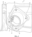
FIGURE 5 illustrates a portion of the audio system ofFigure 1 , showing a front view of the side door. -
FIGURE 6 illustrates a portion of the audio system ofFigure 1 , showing the interior of the side door with the speaker housing and vent tube separated from the side door. - As required, detailed embodiments of the present invention are disclosed herein; however, it is to be understood that the disclosed embodiments are merely exemplary of the invention that may be embodied in various and alternative forms. The figures are not necessarily to scale; some features may be exaggerated or minimized to show details of particular components. Therefore, specific structural and functional details disclosed herein are not to be interpreted as limiting, but merely as a representative basis for teaching one skilled in the art to variously employ the present invention.
-
Figure 1 illustrates avehicle 10 having afront door 12 connected to theA-pillar 14 of thevehicle 10 by a hinge along aforward side 16. In addition, thedoor 12 is framed by aroof support 18, a B-pillar 20 and asill 22. When thedoor 12 is closed, anupper side 24 of the door seals with theroof support 18, arear side 28 of the door seals and latches with the B-pillar 20 and abottom side 30 seals with thesill 22. Aloudspeaker 34 is installed in a cavity in thefront door 12. - The
vehicle 10 may also have arear door 42 connected to the B-pillar 20 of the vehicle. Therear door 42 may be connected by a hinge along the B-pillar 20, or may latch along the B-pillar 20 and slide longitudinally or open in another direction. In addition, therear door 42 is framed by theroof support 18, a C-pillar 44 and thesill 22. When thedoor 12 is closed, anupper side 46 seals with theroof support 18, arear side 48 seals and/or latches with the C-pillar 44 and abottom side 50 seals with thesill 22. Aloudspeaker 34 may be similarly installed in a cavity in therear door 42. - The vehicle includes an audio system having a bass-
compatible speaker 34 installed in thedoors speaker 34 is installed in acavity 54 below thewindows 36. The bass-compatible speaker 34 is designed to at least emit sound in a portion of the bass-range in addition to emitting frequencies outside of the bass-range. It is difficult to have a large enough resonant volume in a cavity enclosed by the door underneath the windows because components such as window-lifting mechanisms, wiring, side airbags, locking devices and other vehicle components are located in this area. Therefore, speakers provided in doors without adequate resonant volume cavities may produce inadequate low-frequency output, excessive mechanical vibration and/or other undesirable effects such as buzz, squeak, and rattle. This can be a particular problem for loudspeakers that provide low-frequency sound, such as a bass-compatible speaker, which require a large resonant volume. - A bass-compatible speaker may include a subwoofer, a traditional woofer or other bass speaker that operates in the bass-range. In general, the bass-range is a low frequency range, which may be around 20 Hertz (Hz) to 400 Hz. In the bass-range, subwoofers generally emit sound between 20 Hz and 200 Hz, and traditional woofers generally emit sound between 40 Hz and 400 Hz.
- The bass-range sound in the door-mounted
speakers 34 is improved by providing a pathway so that the back side of the speaker is in fluid communication with the atmosphere outside of thepassenger compartment 38 and/or outside the vehicle. The front side of the speaker refers to the sound-emitting side of the speaker and is generally in fluid communication with thepassenger compartment 38 of the vehicle. - As generally shown in
Figure 1 , thespeakers 34 are in fluid communication with the atmosphere via aduct 60. Thefront speaker 34 is in fluid communication with the atmosphere via theduct 60 and an opening in thewheel well 62. Theduct 60 may also be routed to be in fluid communication with the atmosphere via the engine compartment or anther suitable location. In another embodiment, the back side of the speaker may be in fluid communication an additional cavity or cavities outside of thepassenger compartment 38, but within the vehicle via theduct 60. - The
rear speaker 34 is in fluid communication with the atmosphere via theduct 60 and an opening in the B-pillar 20 along theunderside 64 of the vehicle. Theduct 60 may also be routed to be in fluid communication with the atmosphere via the sill, for sliding rear door applications, or another suitable location. - When the back side of the speaker is in fluid communication with the atmosphere outside of the vehicle, the speaker is considered to have an infinite baffle. One benefit of having the back side of the speaker in fluid communication with the open atmosphere is that undesirable resonances in the speaker are reduced because sound waves emitted from the back side of the speaker do not interfere with sound waves emitted from the front side of the speaker. Additionally, another benefit of the open environment, or infinite baffle, is that strain in the diaphragm is reduced because the back side of the speaker vents to the outside atmosphere. As a result, the speaker open to the atmosphere outside the vehicle produces a higher sound pressure level (SPL) at low frequency ranges inside the vehicle.
- Another benefit of having the back side of the speaker in fluid communication with the open atmosphere is that sealed speaker enclosures within the door can be eliminated. Removing sealed speaker enclosures reduces cost, complexity and weight. Even in designs where the volume of the door cavity itself provides a resonant volume, like in
European Patent EP1407934 , door treatments that are required prove a sealed resonance volume can be eliminated. By not requiring the door components to provide a sealed cavity, manufacturability is increased, also providing cost and component savings. -
Figure 2 shows the interior 70 of thefront side door 12 that faces thepassenger compartment 38. Theside door 12 has aspeaker mounting cavity 54 or mounting location. Thespeaker housing 74 andspeaker 34 are mounted to the interior 70 of the door withfasteners 78 at thespeaker cavity 54.Figure 2 also illustrates thehinge area 88 when thevehicle door 12 is in a hinged open position. -
Figure 3 shows the interior 70 of thefront side door 12 in more detail with the speaker removed. Thespeaker housing 74 has areceptacle 76 for receiving the speaker. Anoutlet aperture 80 is defined along a surface of thehousing receptacle 76. Theoutlet aperture 80 may be positioned closer to theforward side 16 of thedoor 12.Figure 3 further illustrates thehinge area 88 in closer detail when thevehicle door 12 is in the hinged open position. Theduct 60 may be flexible to accommodate movement required along the hingedopening 88 when thedoor 34 moves between hinged open and closed positions. -
Figure 4 further illustrates thespeaker 34 andhinge area 88 in more detail when thevehicle door 12 is in the hinged open position. Aduct 60 is coupled to theaperture 80 at afirst end 66 and is routed toward theforward side 16 of thedoor 12. Theduct 60 may be sealed to theaperture 80 with adhesive or sealed by any suitable method. Alternatively, theduct 60 may be formed as a single piece with thehousing 74. Theduct 60 is fluidly sealed between thefirst end 66 and second end 68 (Figure 1 ) in order to prevent sound from the back side of the speaker from entering the passenger compartment and to be only in fluid communication with the atmosphere outside the vehicle without leaks that may cause vibrations or may diminish speaker performance and/or output. - The
duct 60 extends from theforward side 16 of thedoor 12 to thefront body 82 of thevehicle 10. Theduct 60 extends to an opening in thefront vehicle body 82 that is open and in fluid communication with the atmosphere. For example, the second end of theduct 60 may extend to an opening in the wheel well 62, as shown inFigure 1 . The opening in the wheel well 62 may be concealed, so that it is not easily visible from outside the vehicle. Similarly, theduct 60 may be routed along the front of the vehicle to an opening in the engine compartment. By visually concealing the second end of theduct 60, the aesthetics and design characteristics of the vehicle are not affected. - As shown better in
Figures 4-6 , theduct 60 may be formed of flexible rubber hose or grommet material. Theduct 60 is able to bend and extend across thehinge area 88 between theforward side 16 of thedoor 12 and thefront body 82 of the vehicle as thedoor 12 opens and closes. Vehicles may have grommet or hose that extends from between the door and the body that contains electrical wiring for controlling door functions such as the electric window and locks. Theduct 60 may include the wiring, or may be a separate hose. -
Figure 6 illustrates thespeaker housing 74 removed from the vehicle door. As shown inFigure 6 , thespeaker housing 74 is not a sealed resonance volume. Thespeaker housing 74 has areceptacle 76 for receiving thespeaker 34 from theinterior 70 of the vehicle. Thespeaker housing 74 may also have a exterior opening. - In order to effectively vent the speaker to the atmosphere, the cross-sectional area 90 (
Fig. 3 ) of theduct 60 andoutlet aperture 80 is generally at least twenty-five percent of the area of the speaker's cone 92 (Fig. 2 ). When the cross-sectional area 90 is at least generally twenty-five percent of thecone area 92, the acoustic resonance is minimized. - A noise, vibration and harshness (NVH) hat and/or acoustic resistive material may be added to the
outlet aperture 80 or at the second end of theduct 60 to provide noise isolation from the outside atmosphere while allowing fluid communication between thespeakers 34 and the outside environment. Even with the back side of the speaker in fluid communication with the open environment outside of the vehicle, unwanted resonance is significantly reduced while outside noise is minimized or prevent from entering the vehicle via the acoustic resistive material. Accordingly, sound quality in the bass-range is improved due to the reduced mechanical vibration as well as the multi-directional emission of the bass-range. - The
vehicle 10 may also include a control unit that is in communication with each of thespeakers 34. The audio control unit may manage bass and sound distribution that may be emitted outside of a vehicle via theduct 60, as described in International Patent Application No.PCT/US16/15393 by Harman International Industries, Inc. , the disclosure of which is incorporated by reference herein. For example, the control unit may adjust the sound pressure level of thespeakers 34 and/or redistribute bass-range emissions based on operation of the vehicle, such as the vehicle speed. - While exemplary embodiments are described above, it is not intended that these embodiments describe all possible forms of the invention. Rather, the words used in the specification are words of description rather than limitation, and it is understood that various changes may be made without departing from the spirit and scope of the invention. Additionally, the features of various implementing embodiments may be combined to form further embodiments of the invention.
- Example 1. An audio system for a vehicle comprising: a bass-range speaker mounted in a vehicle cavity, the bass-range speaker having a front side for producing an acoustic output in a passenger compartment of the vehicle, wherein the vehicle cavity encloses a back side of the bass-range speaker; and a duct having a first end and a second end, the first end being in communication with the vehicle cavity and the second end being in fluid communication with the atmosphere outside the vehicle.
- Example 2. The audio system of example 1, wherein the vehicle cavity is formed in a vehicle door.
- Example 3. The audio system of example 2, wherein the duct extends from a forward side of the vehicle door across a hinge area between the vehicle door and a body structure of the vehicle.
- Example 4. The audio system of example 1, wherein the second end of the duct is positioned adjacent an opening formed in a wheel well of the vehicle.
- Example 5. The audio system of example 1, wherein the second end of the duct is positioned in an engine compartment of the vehicle.
- Example 6. The audio system of example 1, wherein the second end of the duct is in fluid communication with a B-pillar of the vehicle, wherein the B-pillar has an opening in fluid communication with the atmosphere outside the vehicle.
- Example 7. The audio system of example 3, wherein at least a portion of the duct is contained in a grommet along the hinge area, and wherein the grommet contains electrical wiring.
- Example 8. The audio system of example 1, wherein the duct has a cross-sectional area being at least twenty-five percent of a cone area of the speaker.
- Example 9. The audio system of example 1, wherein the bass-range speaker is fluidly sealed between the first end and the second end.
- Example 10. The audio system of example 1, wherein at least a portion of the duct is flexible.
- Example 11. An audio system for a vehicle comprising: a speaker housing mounted in the vehicle; a bass-range speaker mounted in the speaker housing for producing low frequency acoustic output from a front side of the bass-range speaker to a passenger compartment of the vehicle, the speaker housing enclosing a back side of the bass-range speaker; and a duct having a proximal end extending to a distal end, the proximal end being fluidly sealed in the speaker housing and the distal end being in fluid communication with the atmosphere outside the vehicle.
- Example 12. The audio system of example 11, wherein the speaker housing is not a sealed resonance volume.
- Example 13. The audio system of example 11, wherein the bass-range speaker is mounted in a door of the vehicle and the duct extends from a forward side of the door across a hinge area between the vehicle door and a forward body structure, wherein the distal end is fluidly connected to the forward body structure of the vehicle being open to the atmosphere.
- Example 14. The audio system of example 13, wherein at least one of the proximal end and the distal end of the duct is covered in an acoustic resistive material to minimize noise from the atmosphere in the passenger compartment of the vehicle.
- Example 15. The audio system of example 11, wherein the duct has a cross-sectional area being at least twenty-five percent of a cone area of the speaker.
- Example 16. The audio system of example 11, wherein the duct is fluidly sealed between the proximal end and the distal end.
- Example 17. A method for arranging an audio system in a vehicle comprising: mounting a speaker in a cavity in the vehicle; providing a duct having a first end in fluid communication with the cavity and a second end in fluid communication with the atmosphere outside the vehicle.
- Example 18. The method of example 17, further comprising routing the duct to extend across a hinge area between a vehicle door and a vehicle body structure.
- Example 19. The method of example 18, further comprising: routing at least a portion of the duct through a grommet along the hinge area; and routing electrical wiring through the grommet adjacent the portion of the duct.
- Example 20. The method of example 17, wherein the duct has a cross-sectional area being at least twenty-five percent of a cone area of the speaker.
Claims (15)
- An audio system for a vehicle comprising:a bass-range speaker mounted in a vehicle cavity, the bass-range speaker having a front side for producing an acoustic output in a passenger compartment of the vehicle, wherein the vehicle cavity encloses a back side of the bass-range speaker; anda duct extending across a hinge area of a vehicle door, the duct having a first end in communication with the vehicle cavity and a second end being in fluid communication with the atmosphere outside the vehicle;characterized in thata grommet is disposed in the hinge area of the vehicle door, wherein the grommet contains electrical wiring and at least a portion of the duct.
- The audio system of claim 1, wherein the vehicle cavity is formed in the vehicle door.
- The audio system of any of claims 1 to 2, wherein the grommet extends from a forward side of the vehicle door across a hinge area between the vehicle door and a body structure of the vehicle.
- The audio system of any of claims 1 to 3, wherein the second end of the duct is positioned adjacent an opening formed in at least one of a wheel well or an engine compartment of the vehicle.
- The audio system of any of claims 1 to 4, wherein the second end of the duct is in fluid communication with a B-pillar of the vehicle, wherein the B-pillar has an opening in fluid communication with the atmosphere outside the vehicle.
- The audio system of any of claims 1 to 5, wherein a cross-sectional area of the duct is constant from the first end to the second end.
- The audio system of any of claims 1 to 6, wherein the duct has a cross-sectional area being at least twenty-five percent of a cone area of the speaker and is maintained in the grommet.
- The audio system of any of claims 1 to 7, wherein the duct is fluidly sealed between the first end and the second end.
- The audio system of any of claims 1 to 8, wherein at least a portion of the duct is flexible.
- The audio system of any of claims 1 to 9, wherein at least one of the first end and the second end of the duct is covered in an acoustic resistive material to minimize noise from the atmosphere in the passenger compartment of the vehicle.
- A method for arranging an audio system in a vehicle comprising:mounting a speaker in a cavity in the vehicle;providing a duct having a first end in fluid communication with the cavity and a second end in fluid communication with the atmosphere outside the vehicle;routing at least a portion of the duct through a grommet extending in a hinge area between a vehicle door and a body structure; androuting electrical wiring through the grommet adjacent the portion of the duct.
- The method of claim 11, wherein the cavity is formed in a door of the vehicle.
- The method of claim 11 or claim 12, further comprising:
sealing the duct at the first and second end between the cavity and an opening in a body structure. - The method of claim 13, wherein the body structure comprises at least one of a wheel well or an engine compartment of the vehicle.
- The method of any of claims 11-14, wherein the duct has a cross-sectional area being at least twenty-five percent of a cone area of the speaker, wherein the cross-sectional area of the duct is constant and maintained within the grommet.
Applications Claiming Priority (3)
| Application Number | Priority Date | Filing Date | Title |
|---|---|---|---|
| US201662334154P | 2016-05-10 | 2016-05-10 | |
| PCT/US2017/031895 WO2017196935A1 (en) | 2016-05-10 | 2017-05-10 | Vehicle speaker arrangement |
| EP17725406.7A EP3456065B1 (en) | 2016-05-10 | 2017-05-10 | Vehicle speaker arrangement |
Related Parent Applications (1)
| Application Number | Title | Priority Date | Filing Date |
|---|---|---|---|
| EP17725406.7A Division EP3456065B1 (en) | 2016-05-10 | 2017-05-10 | Vehicle speaker arrangement |
Publications (1)
| Publication Number | Publication Date |
|---|---|
| EP4171062A1 true EP4171062A1 (en) | 2023-04-26 |
Family
ID=58765924
Family Applications (2)
| Application Number | Title | Priority Date | Filing Date |
|---|---|---|---|
| EP17725406.7A Active EP3456065B1 (en) | 2016-05-10 | 2017-05-10 | Vehicle speaker arrangement |
| EP22211647.7A Pending EP4171062A1 (en) | 2016-05-10 | 2017-05-10 | Vehicle speaker arrangement |
Family Applications Before (1)
| Application Number | Title | Priority Date | Filing Date |
|---|---|---|---|
| EP17725406.7A Active EP3456065B1 (en) | 2016-05-10 | 2017-05-10 | Vehicle speaker arrangement |
Country Status (6)
| Country | Link |
|---|---|
| US (1) | US10904656B2 (en) |
| EP (2) | EP3456065B1 (en) |
| JP (1) | JP7118896B2 (en) |
| KR (1) | KR102378475B1 (en) |
| CN (1) | CN109076281B (en) |
| WO (1) | WO2017196935A1 (en) |
Families Citing this family (10)
| Publication number | Priority date | Publication date | Assignee | Title |
|---|---|---|---|---|
| US10882461B2 (en) * | 2018-01-16 | 2021-01-05 | Bose Corporation | Waveguide enabled externally ducted vehicle loudspeaker |
| US12330566B2 (en) | 2019-08-06 | 2025-06-17 | Dr. Ing. H.C. F. Porsche Aktiengesellschaft | Pressure control in externally ducted loudspeakers |
| US11377041B2 (en) | 2019-08-06 | 2022-07-05 | Bose Corporation | Pressure control in externally ducted loudspeakers |
| CN114424582B (en) * | 2019-10-10 | 2025-06-13 | 蓝图声学股份有限公司 | Improved speaker assembly and system for a vehicle |
| WO2021080595A1 (en) * | 2019-10-25 | 2021-04-29 | Harman International Industries, Incorporated | Loudspeaker system layout for generating low frequency audio outputs in individual sound zones |
| CN114829203A (en) * | 2019-12-19 | 2022-07-29 | 哈曼国际工业有限公司 | Loudspeaker enclosure integration system |
| US11627394B2 (en) * | 2019-12-31 | 2023-04-11 | Harman International Industries, Incorporated | Loudspeaker assembly for providing audio external to a vehicle |
| JP7666145B2 (en) * | 2021-06-08 | 2025-04-22 | ヤマハ株式会社 | vehicle |
| CN113423032B (en) * | 2021-06-30 | 2022-08-05 | 东风汽车集团股份有限公司 | A column system with loudspeaker sealing structure |
| US11589156B1 (en) * | 2021-10-19 | 2023-02-21 | Harman International Industries, Incorporated | Externally coupled loudspeaker assembly with flexible port |
Citations (5)
| Publication number | Priority date | Publication date | Assignee | Title |
|---|---|---|---|---|
| EP1040968A2 (en) * | 1999-04-02 | 2000-10-04 | Sumitomo Wiring Systems, Ltd. | A cable arrangement for a door wire harness and a grommet therefor |
| EP1407934A1 (en) | 2002-09-27 | 2004-04-14 | Harman/Becker Automotive Systems GmbH | Sound system for a vehicle |
| EP2654319A2 (en) * | 2012-04-17 | 2013-10-23 | Alpine Electronics, Inc. | Speaker |
| US20140093113A1 (en) * | 2012-09-28 | 2014-04-03 | Apple Inc. | Speaker assembly |
| EP2858377A1 (en) * | 2013-10-03 | 2015-04-08 | Alpine Electronics, Inc. | In-Car Audio System |
Family Cites Families (60)
| Publication number | Priority date | Publication date | Assignee | Title |
|---|---|---|---|---|
| US4085289A (en) | 1976-10-18 | 1978-04-18 | Schmideler Jeffrey B | Loudspeaker system |
| JP2590881B2 (en) | 1987-05-20 | 1997-03-12 | 日本ビクター株式会社 | Waveform distortion detection method and receiver |
| JPS63287296A (en) * | 1987-05-20 | 1988-11-24 | Honda Motor Co Ltd | Car speaker device |
| US5218175A (en) | 1991-01-03 | 1993-06-08 | Bose Corporation | Vehicle electroacoustical transducing |
| JPH07267003A (en) | 1994-03-29 | 1995-10-17 | Fujitsu Ten Ltd | Vehicular speaker system |
| JPH07304398A (en) | 1994-05-12 | 1995-11-21 | Kanto Auto Works Ltd | Door speaker device for automobile |
| JPH08253082A (en) | 1995-03-15 | 1996-10-01 | Kanto Auto Works Ltd | Automotive door speaker device |
| DE19735082A1 (en) | 1997-08-13 | 1999-02-18 | Bayerische Motoren Werke Ag | Low frequency loudspeaker for use under motor vehicle seat |
| DE19909143C2 (en) | 1999-03-03 | 2003-12-18 | Daimler Chrysler Ag | Bassbox of a sound system of a motor vehicle |
| EP1106439A3 (en) | 1999-12-09 | 2002-06-26 | Bose Corporation | Automobile pillar electroacoustical transducing |
| AU2001229397A1 (en) | 2000-01-11 | 2001-07-24 | Sai Automotive Usa-Sal, Inc. | Acoustic chamber integrated with vehicle door |
| US6912290B1 (en) | 2000-11-16 | 2005-06-28 | Alpine Electronics, Inc. | Speaker unit for low frequency reproduction |
| US7457425B2 (en) | 2001-02-09 | 2008-11-25 | Thx Ltd. | Vehicle sound system |
| JP2002240643A (en) | 2001-02-16 | 2002-08-28 | Kenwood Corp | Speaker fitting structure |
| ITRE20010069A1 (en) | 2001-06-15 | 2002-12-15 | Ask Ind Spa | VEHICLE SEAT, WITH SUBWOOFER SPEAKER BOX |
| US6868937B2 (en) | 2002-03-26 | 2005-03-22 | Alpine Electronics, Inc | Sub-woofer system for use in vehicle |
| US20030215101A1 (en) | 2002-05-15 | 2003-11-20 | Siemens Vdo Automotive, Inc. | Active noise control system with an elongated transmission member |
| KR100510708B1 (en) | 2003-04-09 | 2005-08-26 | 현대모비스 주식회사 | Auto volume controlling device tuned by car speed and its operating method |
| US7606376B2 (en) | 2003-11-07 | 2009-10-20 | Harman International Industries, Incorporated | Automotive audio controller with vibration sensor |
| EP1729541A1 (en) | 2004-03-24 | 2006-12-06 | Pioneer Corporation | Voice output device, voice signal output regulating method, and voice signal output regulation processing program or the like |
| US7073843B2 (en) | 2004-04-06 | 2006-07-11 | Lear Corporation | Trim panel assembly and method of manufacture |
| DE102005046594B3 (en) | 2005-09-28 | 2007-03-08 | Daimlerchrysler Ag | Loudspeaker system for passenger motor vehicle, has two units of support structure e.g. sill, chassis beam and cross beam volumes that meet one another so that part of resonating cavity is formed together by cavities of any two volumes |
| EP1773092A3 (en) | 2005-10-04 | 2009-05-20 | Gealan Formteile GmbH | Enclosure with sealing arrangement |
| JP4665702B2 (en) | 2005-10-14 | 2011-04-06 | 三菱自動車工業株式会社 | Vehicle door structure |
| JP4717679B2 (en) | 2006-03-28 | 2011-07-06 | 京セラ株式会社 | Portable wireless terminal |
| DE102006023909B3 (en) | 2006-05-19 | 2007-07-19 | Daimlerchrysler Ag | Loudspeaker e.g. woofer, box for e.g. automobile, has subspaces formed for support structure by two of three units e.g. sill, cross beam and chassis beam, and sound transducer integrated in area, at which two units strike on each other |
| US20080101645A1 (en) | 2006-10-20 | 2008-05-01 | Rosen Michael D | Low frequency electroacoustical transducing in a vehicle |
| US7881488B2 (en) | 2006-11-01 | 2011-02-01 | Bose Corporation | In-plane speaker |
| US7628249B2 (en) | 2007-06-07 | 2009-12-08 | Chrysler Group Llc | Automotive speaker enclosure |
| US20090154726A1 (en) | 2007-08-22 | 2009-06-18 | Step Labs Inc. | System and Method for Noise Activity Detection |
| EP2043382B1 (en) | 2007-09-25 | 2014-03-05 | Harman International Industries Ltd. | Sound system |
| US8126187B2 (en) | 2007-10-29 | 2012-02-28 | Bose Corporation | Vehicle audio system including door-mounted components |
| EP2077680B1 (en) | 2007-12-14 | 2013-09-11 | Harman International Industries Ltd. | Loudspeaker system with double chamber enclosure |
| DE102008015490A1 (en) | 2008-03-25 | 2009-10-01 | Bayerische Motoren Werke Aktiengesellschaft | Motor vehicle, has resonance volumes provided for low-frequency loud speaker, and partially limited by bottom plate, where bottom plate represents lower-sided limitation of resonance volumes |
| EP2119598B1 (en) | 2008-05-09 | 2010-09-22 | Harman Becker Automotive Systems GmbH | Speaker assembly arrangement and method of mounting a speaker |
| EP2211562A1 (en) | 2009-01-22 | 2010-07-28 | Ford Global Technologies, LLC | Loudspeaker installation |
| EP2491547B1 (en) | 2009-10-23 | 2020-01-15 | Harman International Industries, Incorporated | System for simulated multi-gear vehicle sound generation |
| US8804991B2 (en) | 2009-10-23 | 2014-08-12 | Blueprint Acoustics Pty Ltd | Loudspeaker assembly and system |
| JP5545662B2 (en) | 2010-12-08 | 2014-07-09 | アルパイン株式会社 | In-vehicle speaker device |
| US8469447B2 (en) | 2011-01-27 | 2013-06-25 | Honda Motor Co., Ltd. | Vehicle seat and subwoofer enclosure seat support structure |
| US8837768B2 (en) | 2011-03-28 | 2014-09-16 | Bose Corporation | Electro-acoustic transducer enclosure |
| EP2530835B1 (en) | 2011-05-30 | 2015-07-22 | Harman Becker Automotive Systems GmbH | Automatic adjustment of a speed dependent equalizing control system |
| DE102011105474A1 (en) | 2011-06-24 | 2012-12-27 | Norman Gerkinsmeyer | Subwoofer for use in passenger car, has absorption plate mounted below seat surface over resonance and oscillation-decoupling materials, where subwoofer works according to passive vibrator and/or passive radiator principle |
| JP2013095312A (en) | 2011-11-02 | 2013-05-20 | Alpine Electronics Inc | On-vehicle acoustic device and method for assembling the same |
| JP5820253B2 (en) | 2011-12-05 | 2015-11-24 | アルパイン株式会社 | Speaker |
| JP5967645B2 (en) | 2012-01-24 | 2016-08-10 | アルパイン株式会社 | Installation structure of speaker device in vehicle |
| DE102012003769B3 (en) | 2012-02-24 | 2013-07-04 | Audi Ag | Speaker system for a motor vehicle |
| DE102012003772B4 (en) | 2012-02-24 | 2014-01-23 | Audi Ag | Speaker system for a motor vehicle |
| WO2013150735A1 (en) * | 2012-04-04 | 2013-10-10 | パナソニック株式会社 | Sounding body and audio reproduction device using same, and mobile device |
| JP5955079B2 (en) | 2012-04-25 | 2016-07-20 | アルパイン株式会社 | Speaker device |
| US8649548B1 (en) | 2012-08-14 | 2014-02-11 | Bose Corporation | Structure having acoustic transducer volume |
| DE102012107814B4 (en) | 2012-08-24 | 2024-09-12 | Dr. Ing. H.C. F. Porsche Aktiengesellschaft | Method and device for generating noise in the interior and exterior of a motor vehicle |
| CN203047053U (en) | 2012-12-20 | 2013-07-10 | 北汽福田汽车股份有限公司 | Installing structure of subwoofer and vehicle |
| JP6177552B2 (en) | 2013-03-15 | 2017-08-09 | アルパイン株式会社 | Speaker device |
| CN203491984U (en) | 2013-08-30 | 2014-03-19 | 深圳市诺威达科技有限公司 | Automatic gain processing system |
| DE102013020672A1 (en) | 2013-12-11 | 2014-08-14 | Daimler Ag | Motor car has active acoustic transducer which is positioned at cross beam of supporting structure connected to two longitudinal beams, where cavity of cross beam is matched with cavities of longitudinal beams to form resonant space |
| US9573523B2 (en) | 2014-07-15 | 2017-02-21 | Harman International Industries, Inc. | Spatial sonification of accelerating objects |
| US9549243B2 (en) | 2014-12-11 | 2017-01-17 | GM Global Technology Operations LLC | Split box subwoofer with body mounted driver |
| WO2016123360A1 (en) | 2015-01-28 | 2016-08-04 | Harman International Industries, Inc. | Vehicle speaker arrangement |
| CN204895329U (en) | 2015-08-31 | 2015-12-23 | 丰顺县培英电声有限公司 | Speaker mounting structure |
-
2017
- 2017-05-10 WO PCT/US2017/031895 patent/WO2017196935A1/en not_active Ceased
- 2017-05-10 US US16/301,025 patent/US10904656B2/en active Active
- 2017-05-10 EP EP17725406.7A patent/EP3456065B1/en active Active
- 2017-05-10 EP EP22211647.7A patent/EP4171062A1/en active Pending
- 2017-05-10 JP JP2018556881A patent/JP7118896B2/en active Active
- 2017-05-10 KR KR1020187032188A patent/KR102378475B1/en active Active
- 2017-05-10 CN CN201780029171.9A patent/CN109076281B/en active Active
Patent Citations (6)
| Publication number | Priority date | Publication date | Assignee | Title |
|---|---|---|---|---|
| EP1040968A2 (en) * | 1999-04-02 | 2000-10-04 | Sumitomo Wiring Systems, Ltd. | A cable arrangement for a door wire harness and a grommet therefor |
| EP1407934A1 (en) | 2002-09-27 | 2004-04-14 | Harman/Becker Automotive Systems GmbH | Sound system for a vehicle |
| US20040141625A1 (en) * | 2002-09-27 | 2004-07-22 | Kurt Leipold | Sound system for a vehicle |
| EP2654319A2 (en) * | 2012-04-17 | 2013-10-23 | Alpine Electronics, Inc. | Speaker |
| US20140093113A1 (en) * | 2012-09-28 | 2014-04-03 | Apple Inc. | Speaker assembly |
| EP2858377A1 (en) * | 2013-10-03 | 2015-04-08 | Alpine Electronics, Inc. | In-Car Audio System |
Also Published As
| Publication number | Publication date |
|---|---|
| EP3456065B1 (en) | 2022-12-07 |
| CN109076281A (en) | 2018-12-21 |
| US10904656B2 (en) | 2021-01-26 |
| US20190182584A1 (en) | 2019-06-13 |
| WO2017196935A1 (en) | 2017-11-16 |
| KR102378475B1 (en) | 2022-03-24 |
| CN109076281B (en) | 2021-03-23 |
| JP7118896B2 (en) | 2022-08-16 |
| KR20190002511A (en) | 2019-01-08 |
| EP3456065A1 (en) | 2019-03-20 |
| JP2019520724A (en) | 2019-07-18 |
Similar Documents
| Publication | Publication Date | Title |
|---|---|---|
| US10904656B2 (en) | Vehicle speaker arragement | |
| JP6833284B2 (en) | A loudspeaker system for vehicles and a vehicle structure equipped with this loudspeaker system. | |
| JP7418160B2 (en) | invisible headliner microphone | |
| EP2087768B1 (en) | In-plane speaker | |
| CN1285469C (en) | Mounting structure of speaker for vehicle | |
| US9716941B2 (en) | Frame rail-integrated subwoofer assembly and method | |
| US20200245067A1 (en) | Speaker apparatus | |
| US11627394B2 (en) | Loudspeaker assembly for providing audio external to a vehicle | |
| EP2941011B1 (en) | A vehicle installation structure comprising a loudspeaker device for attaching to a vehicle panel | |
| US20090310812A1 (en) | Door Speaker Enclosure with Integral Water Barrier and Hardware Attachment | |
| US20220363202A1 (en) | Externally coupled loudspeaker assembly for a vehicle | |
| JPS63287296A (en) | Car speaker device | |
| AU2020363457B2 (en) | Improved loudspeaker assembly and system for vehicles | |
| CN109660912B (en) | Vehicle-mounted sound box and automobile | |
| EP4171063B1 (en) | Externally coupled loudspeaker assembly with flexible port | |
| JPS63211999A (en) | Car speaker device | |
| KR100486482B1 (en) | Door for automobile | |
| JP2022186385A (en) | On-vehicle subwoofer unit | |
| EP4601319A1 (en) | Vehicle loudspeaker system and vehicle structure comprising such loudspeaker system | |
| JP2005033749A (en) | Vehicle upholstery material |
Legal Events
| Date | Code | Title | Description |
|---|---|---|---|
| PUAI | Public reference made under article 153(3) epc to a published international application that has entered the european phase |
Free format text: ORIGINAL CODE: 0009012 |
|
| STAA | Information on the status of an ep patent application or granted ep patent |
Free format text: STATUS: THE APPLICATION HAS BEEN PUBLISHED |
|
| AC | Divisional application: reference to earlier application |
Ref document number: 3456065 Country of ref document: EP Kind code of ref document: P |
|
| AK | Designated contracting states |
Kind code of ref document: A1 Designated state(s): AL AT BE BG CH CY CZ DE DK EE ES FI FR GB GR HR HU IE IS IT LI LT LU LV MC MK MT NL NO PL PT RO RS SE SI SK SM TR |
|
| STAA | Information on the status of an ep patent application or granted ep patent |
Free format text: STATUS: REQUEST FOR EXAMINATION WAS MADE |
|
| 17P | Request for examination filed |
Effective date: 20231026 |
|
| RBV | Designated contracting states (corrected) |
Designated state(s): AL AT BE BG CH CY CZ DE DK EE ES FI FR GB GR HR HU IE IS IT LI LT LU LV MC MK MT NL NO PL PT RO RS SE SI SK SM TR |
|
| STAA | Information on the status of an ep patent application or granted ep patent |
Free format text: STATUS: EXAMINATION IS IN PROGRESS |
|
| 17Q | First examination report despatched |
Effective date: 20250428 |