EP4170882A1 - Circuit de protection, convertisseur cc-cc, chargeur de batterie et véhicule électrique - Google Patents
Circuit de protection, convertisseur cc-cc, chargeur de batterie et véhicule électrique Download PDFInfo
- Publication number
- EP4170882A1 EP4170882A1 EP21864590.1A EP21864590A EP4170882A1 EP 4170882 A1 EP4170882 A1 EP 4170882A1 EP 21864590 A EP21864590 A EP 21864590A EP 4170882 A1 EP4170882 A1 EP 4170882A1
- Authority
- EP
- European Patent Office
- Prior art keywords
- voltage
- protection
- node
- buck
- state
- Prior art date
- Legal status (The legal status is an assumption and is not a legal conclusion. Google has not performed a legal analysis and makes no representation as to the accuracy of the status listed.)
- Pending
Links
- 239000003990 capacitor Substances 0.000 claims abstract description 43
- 238000004891 communication Methods 0.000 description 10
- 238000010586 diagram Methods 0.000 description 10
- PXHVJJICTQNCMI-UHFFFAOYSA-N Nickel Chemical compound [Ni] PXHVJJICTQNCMI-UHFFFAOYSA-N 0.000 description 9
- 230000004044 response Effects 0.000 description 6
- 238000012986 modification Methods 0.000 description 4
- 230000004048 modification Effects 0.000 description 4
- 239000013256 coordination polymer Substances 0.000 description 3
- 230000000694 effects Effects 0.000 description 3
- 239000000126 substance Substances 0.000 description 3
- WHXSMMKQMYFTQS-UHFFFAOYSA-N Lithium Chemical compound [Li] WHXSMMKQMYFTQS-UHFFFAOYSA-N 0.000 description 2
- 230000006870 function Effects 0.000 description 2
- 229910052744 lithium Inorganic materials 0.000 description 2
- 238000012545 processing Methods 0.000 description 2
- 239000004065 semiconductor Substances 0.000 description 2
- XUIMIQQOPSSXEZ-UHFFFAOYSA-N Silicon Chemical compound [Si] XUIMIQQOPSSXEZ-UHFFFAOYSA-N 0.000 description 1
- 238000003491 array Methods 0.000 description 1
- OJIJEKBXJYRIBZ-UHFFFAOYSA-N cadmium nickel Chemical compound [Ni].[Cd] OJIJEKBXJYRIBZ-UHFFFAOYSA-N 0.000 description 1
- 230000008859 change Effects 0.000 description 1
- 230000003247 decreasing effect Effects 0.000 description 1
- 238000013461 design Methods 0.000 description 1
- 238000011161 development Methods 0.000 description 1
- 238000004146 energy storage Methods 0.000 description 1
- 238000005516 engineering process Methods 0.000 description 1
- 230000005669 field effect Effects 0.000 description 1
- 229910052739 hydrogen Inorganic materials 0.000 description 1
- 239000001257 hydrogen Substances 0.000 description 1
- 229910001416 lithium ion Inorganic materials 0.000 description 1
- 230000003446 memory effect Effects 0.000 description 1
- 229910044991 metal oxide Inorganic materials 0.000 description 1
- 150000004706 metal oxides Chemical class 0.000 description 1
- 229910052759 nickel Inorganic materials 0.000 description 1
- QELJHCBNGDEXLD-UHFFFAOYSA-N nickel zinc Chemical compound [Ni].[Zn] QELJHCBNGDEXLD-UHFFFAOYSA-N 0.000 description 1
- 230000001151 other effect Effects 0.000 description 1
- 229910052710 silicon Inorganic materials 0.000 description 1
- 239000010703 silicon Substances 0.000 description 1
- 239000007787 solid Substances 0.000 description 1
- 230000003068 static effect Effects 0.000 description 1
- 238000006467 substitution reaction Methods 0.000 description 1
- 229910052720 vanadium Inorganic materials 0.000 description 1
Images


Classifications
-
- H—ELECTRICITY
- H02—GENERATION; CONVERSION OR DISTRIBUTION OF ELECTRIC POWER
- H02M—APPARATUS FOR CONVERSION BETWEEN AC AND AC, BETWEEN AC AND DC, OR BETWEEN DC AND DC, AND FOR USE WITH MAINS OR SIMILAR POWER SUPPLY SYSTEMS; CONVERSION OF DC OR AC INPUT POWER INTO SURGE OUTPUT POWER; CONTROL OR REGULATION THEREOF
- H02M3/00—Conversion of dc power input into dc power output
- H02M3/02—Conversion of dc power input into dc power output without intermediate conversion into ac
- H02M3/04—Conversion of dc power input into dc power output without intermediate conversion into ac by static converters
- H02M3/10—Conversion of dc power input into dc power output without intermediate conversion into ac by static converters using discharge tubes with control electrode or semiconductor devices with control electrode
- H02M3/145—Conversion of dc power input into dc power output without intermediate conversion into ac by static converters using discharge tubes with control electrode or semiconductor devices with control electrode using devices of a triode or transistor type requiring continuous application of a control signal
- H02M3/155—Conversion of dc power input into dc power output without intermediate conversion into ac by static converters using discharge tubes with control electrode or semiconductor devices with control electrode using devices of a triode or transistor type requiring continuous application of a control signal using semiconductor devices only
- H02M3/156—Conversion of dc power input into dc power output without intermediate conversion into ac by static converters using discharge tubes with control electrode or semiconductor devices with control electrode using devices of a triode or transistor type requiring continuous application of a control signal using semiconductor devices only with automatic control of output voltage or current, e.g. switching regulators
-
- H—ELECTRICITY
- H02—GENERATION; CONVERSION OR DISTRIBUTION OF ELECTRIC POWER
- H02M—APPARATUS FOR CONVERSION BETWEEN AC AND AC, BETWEEN AC AND DC, OR BETWEEN DC AND DC, AND FOR USE WITH MAINS OR SIMILAR POWER SUPPLY SYSTEMS; CONVERSION OF DC OR AC INPUT POWER INTO SURGE OUTPUT POWER; CONTROL OR REGULATION THEREOF
- H02M1/00—Details of apparatus for conversion
- H02M1/32—Means for protecting converters other than automatic disconnection
- H02M1/34—Snubber circuits
-
- B—PERFORMING OPERATIONS; TRANSPORTING
- B60—VEHICLES IN GENERAL
- B60L—PROPULSION OF ELECTRICALLY-PROPELLED VEHICLES; SUPPLYING ELECTRIC POWER FOR AUXILIARY EQUIPMENT OF ELECTRICALLY-PROPELLED VEHICLES; ELECTRODYNAMIC BRAKE SYSTEMS FOR VEHICLES IN GENERAL; MAGNETIC SUSPENSION OR LEVITATION FOR VEHICLES; MONITORING OPERATING VARIABLES OF ELECTRICALLY-PROPELLED VEHICLES; ELECTRIC SAFETY DEVICES FOR ELECTRICALLY-PROPELLED VEHICLES
- B60L53/00—Methods of charging batteries, specially adapted for electric vehicles; Charging stations or on-board charging equipment therefor; Exchange of energy storage elements in electric vehicles
- B60L53/20—Methods of charging batteries, specially adapted for electric vehicles; Charging stations or on-board charging equipment therefor; Exchange of energy storage elements in electric vehicles characterised by converters located in the vehicle
- B60L53/22—Constructional details or arrangements of charging converters specially adapted for charging electric vehicles
-
- H—ELECTRICITY
- H02—GENERATION; CONVERSION OR DISTRIBUTION OF ELECTRIC POWER
- H02J—CIRCUIT ARRANGEMENTS OR SYSTEMS FOR SUPPLYING OR DISTRIBUTING ELECTRIC POWER; SYSTEMS FOR STORING ELECTRIC ENERGY
- H02J7/00—Circuit arrangements for charging or depolarising batteries or for supplying loads from batteries
- H02J7/007—Regulation of charging or discharging current or voltage
-
- H—ELECTRICITY
- H02—GENERATION; CONVERSION OR DISTRIBUTION OF ELECTRIC POWER
- H02M—APPARATUS FOR CONVERSION BETWEEN AC AND AC, BETWEEN AC AND DC, OR BETWEEN DC AND DC, AND FOR USE WITH MAINS OR SIMILAR POWER SUPPLY SYSTEMS; CONVERSION OF DC OR AC INPUT POWER INTO SURGE OUTPUT POWER; CONTROL OR REGULATION THEREOF
- H02M1/00—Details of apparatus for conversion
- H02M1/0048—Circuits or arrangements for reducing losses
- H02M1/0054—Transistor switching losses
-
- H—ELECTRICITY
- H02—GENERATION; CONVERSION OR DISTRIBUTION OF ELECTRIC POWER
- H02M—APPARATUS FOR CONVERSION BETWEEN AC AND AC, BETWEEN AC AND DC, OR BETWEEN DC AND DC, AND FOR USE WITH MAINS OR SIMILAR POWER SUPPLY SYSTEMS; CONVERSION OF DC OR AC INPUT POWER INTO SURGE OUTPUT POWER; CONTROL OR REGULATION THEREOF
- H02M1/00—Details of apparatus for conversion
- H02M1/32—Means for protecting converters other than automatic disconnection
- H02M1/34—Snubber circuits
- H02M1/346—Passive non-dissipative snubbers
-
- H—ELECTRICITY
- H02—GENERATION; CONVERSION OR DISTRIBUTION OF ELECTRIC POWER
- H02M—APPARATUS FOR CONVERSION BETWEEN AC AND AC, BETWEEN AC AND DC, OR BETWEEN DC AND DC, AND FOR USE WITH MAINS OR SIMILAR POWER SUPPLY SYSTEMS; CONVERSION OF DC OR AC INPUT POWER INTO SURGE OUTPUT POWER; CONTROL OR REGULATION THEREOF
- H02M3/00—Conversion of dc power input into dc power output
- H02M3/02—Conversion of dc power input into dc power output without intermediate conversion into ac
- H02M3/04—Conversion of dc power input into dc power output without intermediate conversion into ac by static converters
- H02M3/10—Conversion of dc power input into dc power output without intermediate conversion into ac by static converters using discharge tubes with control electrode or semiconductor devices with control electrode
- H02M3/145—Conversion of dc power input into dc power output without intermediate conversion into ac by static converters using discharge tubes with control electrode or semiconductor devices with control electrode using devices of a triode or transistor type requiring continuous application of a control signal
- H02M3/155—Conversion of dc power input into dc power output without intermediate conversion into ac by static converters using discharge tubes with control electrode or semiconductor devices with control electrode using devices of a triode or transistor type requiring continuous application of a control signal using semiconductor devices only
- H02M3/156—Conversion of dc power input into dc power output without intermediate conversion into ac by static converters using discharge tubes with control electrode or semiconductor devices with control electrode using devices of a triode or transistor type requiring continuous application of a control signal using semiconductor devices only with automatic control of output voltage or current, e.g. switching regulators
- H02M3/158—Conversion of dc power input into dc power output without intermediate conversion into ac by static converters using discharge tubes with control electrode or semiconductor devices with control electrode using devices of a triode or transistor type requiring continuous application of a control signal using semiconductor devices only with automatic control of output voltage or current, e.g. switching regulators including plural semiconductor devices as final control devices for a single load
- H02M3/1582—Buck-boost converters
-
- B—PERFORMING OPERATIONS; TRANSPORTING
- B60—VEHICLES IN GENERAL
- B60L—PROPULSION OF ELECTRICALLY-PROPELLED VEHICLES; SUPPLYING ELECTRIC POWER FOR AUXILIARY EQUIPMENT OF ELECTRICALLY-PROPELLED VEHICLES; ELECTRODYNAMIC BRAKE SYSTEMS FOR VEHICLES IN GENERAL; MAGNETIC SUSPENSION OR LEVITATION FOR VEHICLES; MONITORING OPERATING VARIABLES OF ELECTRICALLY-PROPELLED VEHICLES; ELECTRIC SAFETY DEVICES FOR ELECTRICALLY-PROPELLED VEHICLES
- B60L2210/00—Converter types
- B60L2210/10—DC to DC converters
- B60L2210/12—Buck converters
-
- B—PERFORMING OPERATIONS; TRANSPORTING
- B60—VEHICLES IN GENERAL
- B60L—PROPULSION OF ELECTRICALLY-PROPELLED VEHICLES; SUPPLYING ELECTRIC POWER FOR AUXILIARY EQUIPMENT OF ELECTRICALLY-PROPELLED VEHICLES; ELECTRODYNAMIC BRAKE SYSTEMS FOR VEHICLES IN GENERAL; MAGNETIC SUSPENSION OR LEVITATION FOR VEHICLES; MONITORING OPERATING VARIABLES OF ELECTRICALLY-PROPELLED VEHICLES; ELECTRIC SAFETY DEVICES FOR ELECTRICALLY-PROPELLED VEHICLES
- B60L2210/00—Converter types
- B60L2210/30—AC to DC converters
-
- H—ELECTRICITY
- H02—GENERATION; CONVERSION OR DISTRIBUTION OF ELECTRIC POWER
- H02J—CIRCUIT ARRANGEMENTS OR SYSTEMS FOR SUPPLYING OR DISTRIBUTING ELECTRIC POWER; SYSTEMS FOR STORING ELECTRIC ENERGY
- H02J2207/00—Indexing scheme relating to details of circuit arrangements for charging or depolarising batteries or for supplying loads from batteries
- H02J2207/20—Charging or discharging characterised by the power electronics converter
-
- Y—GENERAL TAGGING OF NEW TECHNOLOGICAL DEVELOPMENTS; GENERAL TAGGING OF CROSS-SECTIONAL TECHNOLOGIES SPANNING OVER SEVERAL SECTIONS OF THE IPC; TECHNICAL SUBJECTS COVERED BY FORMER USPC CROSS-REFERENCE ART COLLECTIONS [XRACs] AND DIGESTS
- Y02—TECHNOLOGIES OR APPLICATIONS FOR MITIGATION OR ADAPTATION AGAINST CLIMATE CHANGE
- Y02T—CLIMATE CHANGE MITIGATION TECHNOLOGIES RELATED TO TRANSPORTATION
- Y02T10/00—Road transport of goods or passengers
- Y02T10/60—Other road transportation technologies with climate change mitigation effect
- Y02T10/70—Energy storage systems for electromobility, e.g. batteries
-
- Y—GENERAL TAGGING OF NEW TECHNOLOGICAL DEVELOPMENTS; GENERAL TAGGING OF CROSS-SECTIONAL TECHNOLOGIES SPANNING OVER SEVERAL SECTIONS OF THE IPC; TECHNICAL SUBJECTS COVERED BY FORMER USPC CROSS-REFERENCE ART COLLECTIONS [XRACs] AND DIGESTS
- Y02—TECHNOLOGIES OR APPLICATIONS FOR MITIGATION OR ADAPTATION AGAINST CLIMATE CHANGE
- Y02T—CLIMATE CHANGE MITIGATION TECHNOLOGIES RELATED TO TRANSPORTATION
- Y02T10/00—Road transport of goods or passengers
- Y02T10/60—Other road transportation technologies with climate change mitigation effect
- Y02T10/7072—Electromobility specific charging systems or methods for batteries, ultracapacitors, supercapacitors or double-layer capacitors
-
- Y—GENERAL TAGGING OF NEW TECHNOLOGICAL DEVELOPMENTS; GENERAL TAGGING OF CROSS-SECTIONAL TECHNOLOGIES SPANNING OVER SEVERAL SECTIONS OF THE IPC; TECHNICAL SUBJECTS COVERED BY FORMER USPC CROSS-REFERENCE ART COLLECTIONS [XRACs] AND DIGESTS
- Y02—TECHNOLOGIES OR APPLICATIONS FOR MITIGATION OR ADAPTATION AGAINST CLIMATE CHANGE
- Y02T—CLIMATE CHANGE MITIGATION TECHNOLOGIES RELATED TO TRANSPORTATION
- Y02T10/00—Road transport of goods or passengers
- Y02T10/60—Other road transportation technologies with climate change mitigation effect
- Y02T10/72—Electric energy management in electromobility
-
- Y—GENERAL TAGGING OF NEW TECHNOLOGICAL DEVELOPMENTS; GENERAL TAGGING OF CROSS-SECTIONAL TECHNOLOGIES SPANNING OVER SEVERAL SECTIONS OF THE IPC; TECHNICAL SUBJECTS COVERED BY FORMER USPC CROSS-REFERENCE ART COLLECTIONS [XRACs] AND DIGESTS
- Y02—TECHNOLOGIES OR APPLICATIONS FOR MITIGATION OR ADAPTATION AGAINST CLIMATE CHANGE
- Y02T—CLIMATE CHANGE MITIGATION TECHNOLOGIES RELATED TO TRANSPORTATION
- Y02T10/00—Road transport of goods or passengers
- Y02T10/80—Technologies aiming to reduce greenhouse gasses emissions common to all road transportation technologies
- Y02T10/92—Energy efficient charging or discharging systems for batteries, ultracapacitors, supercapacitors or double-layer capacitors specially adapted for vehicles
-
- Y—GENERAL TAGGING OF NEW TECHNOLOGICAL DEVELOPMENTS; GENERAL TAGGING OF CROSS-SECTIONAL TECHNOLOGIES SPANNING OVER SEVERAL SECTIONS OF THE IPC; TECHNICAL SUBJECTS COVERED BY FORMER USPC CROSS-REFERENCE ART COLLECTIONS [XRACs] AND DIGESTS
- Y02—TECHNOLOGIES OR APPLICATIONS FOR MITIGATION OR ADAPTATION AGAINST CLIMATE CHANGE
- Y02T—CLIMATE CHANGE MITIGATION TECHNOLOGIES RELATED TO TRANSPORTATION
- Y02T90/00—Enabling technologies or technologies with a potential or indirect contribution to GHG emissions mitigation
- Y02T90/10—Technologies relating to charging of electric vehicles
- Y02T90/14—Plug-in electric vehicles
Definitions
- the present disclosure relates to technology for protecting a direct current (DC)-DC converter from switching loss.
- An electric vehicle includes a battery and a battery charger.
- the battery charger generates the charge power for the battery using the input power from an external power source when connected to the external power source through a charging cable.
- the battery charger includes a direct current (DC)-DC converter to generate the output voltage that is lower than the input voltage.
- DC direct current
- FIG. 1 is a schematic diagram of a common DC-DC stepdown converter.
- the DC-DC converter includes a buck switch SW B connected between a voltage input terminal N i and a first node N 1 ; a buck inductor L B connected between the first node N 1 and a voltage output terminal N o ; a buck capacitor C B connected between the voltage output terminal N o and the ground; and a buck diode D B connected between the first node N 1 and the ground.
- the buck switch SW B is switched from an ON state to an OFF state, the buck diode D B is turned on, and voltage which is, in substance, equal to 0V, is supplied between the first node N 1 and the ground.
- the present disclosure is designed to solve the above-described problem, and therefore the present disclosure is directed to providing a protection circuit for protecting a direct current (DC)-DC converter from switching loss, a battery charger comprising the protection circuit and an electric vehicle comprising the battery charger.
- DC direct current
- a protection circuit for a direct current (DC)-DC converter.
- the DC-DC converter includes a buck switch connected between a voltage input terminal and a first node, the buck switch being controlled by a switching cycle and a duty cycle of a switching signal; a buck inductor connected between the first node and a voltage output terminal; a buck diode connected between a second node and a ground; and a buck capacitor connected between the voltage output terminal and the ground.
- the protection circuit is connected to the first node, the second node and the ground.
- the protection circuit is configured to supply a protection voltage between the first node and the ground so that voltage stress of the buck switch is smaller than an input voltage supplied between the voltage input terminal and the ground.
- the protection circuit includes a first protection capacitor connected between the first node and the second node; a second protection capacitor connected between a third node and the ground; a protection inductor connected between the second node and the third node; and a protection diode connected between the first node and the third node.
- the protection diode is kept in the OFF state in a first period of time during which the buck switch is in the ON state.
- the protection diode is kept in the ON state in a second period of time during which the buck switch is in the OFF state.
- the protection voltage may be equal to a voltage of a series circuit of the first protection capacitor and the buck diode.
- a voltage of a series circuit of the first protection capacitor, the protection inductor and the second protection capacitor may be equal to a sum of a voltage of the buck inductor and an output voltage in a first period of time during which the buck switch is in the ON state.
- the output voltage is a voltage between the voltage output terminal and the ground.
- a voltage of the first protection capacitor may be equal to a voltage of a series circuit of the protection inductor and the protection diode in the second period of time during which the buck switch is in the OFF state.
- a voltage of the second protection capacitor may be equal to a voltage of a series circuit of the protection inductor and the buck diode in the second period of time during which the buck switch is in the OFF state.
- a DC-DC converter includes the protection circuit.
- a battery charger according to still another aspect of the present disclosure includes the DC-DC converter.
- An electric vehicle includes the battery charger and a battery connected between the voltage output terminal and the ground.
- control unit refers to a processing unit of at least one function or operation, and this may be implemented by hardware and software either alone or in combination.
- FIG. 2 is an exemplary diagram showing a configuration of an electric vehicle of the present disclosure.
- the electric vehicle 1 includes a battery pack 10, an inverter 30, an electric motor 40 and a battery charger 50.
- the battery pack 10 includes a battery B, a relay 20 and a battery management system 100.
- the battery B includes at least one battery cell. Each battery cell is not limited to a particular type, and may include any battery cell that can be repeatedly recharged such as, for example, a lithium ion cell.
- the battery B may be coupled to the inverter 30 through a pair of power terminals provided in the battery pack 10.
- the relay 20 is connected in series to the battery B.
- the relay 20 is installed on a current path for the charge/discharge of the battery B.
- the on-off control of the relay 20 is performed in response to a control signal from the battery management system 100.
- the relay 20 may be a mechanical relay that is turned on/off by the electromagnetic force of a coil or a semiconductor switch such as a Metal Oxide Semiconductor Field Effect transistor (MOSFET).
- MOSFET Metal Oxide Semiconductor Field Effect transistor
- the inverter 30 is provided to convert the DC power from the battery B to alternating current (AC) power in response to a command from the battery management system 100.
- the electric motor 40 may be, for example, a 3-phase AC motor. The electric motor 40 works using the AC power from the inverter 30.
- the battery management system 100 is provided to perform the general control related to the charge/discharge of the battery B.
- the battery management system 100 includes a sensing unit 110, a memory unit 120 and a control unit 140.
- the battery management system 100 may further include at least one of an interface unit 130 or a switch driver 150.
- the sensing unit 110 includes a voltage sensor 111 and a current sensor 112.
- the sensing unit 110 may further include a temperature sensor 113.
- the voltage sensor 111 is connected in parallel to the battery B, and is configured to detect a battery voltage across the battery B and generate a voltage signal indicating the detected battery voltage.
- the current sensor 112 is connected in series to the battery B through the current path.
- the current sensor 112 is configured to detect a battery current flowing through the battery B and generate a current signal indicating the detected battery current.
- the temperature sensor 113 is configured to detect a temperature of the battery B and generate a temperature signal indicating the detected temperature.
- the memory unit 120 may include at least one type of storage medium of flash memory type, hard disk type, Solid State Disk (SSD) type, Silicon Disk Drive (SDD) type, multimedia card micro type, random access memory (RAM), static random access memory (SRAM), read-only memory (ROM), electrically erasable programmable read-only memory (EEPROM) or programmable read-only memory (PROM).
- the memory unit 120 may store data and programs required for the computation operation by the control unit 140.
- the memory unit 120 may store data indicating the result of the computation operation by the control unit 140.
- the interface unit 130 may include a communication circuit configured to support wired or wireless communication between the control unit 140 and a high-level controller 2 (for example, an Electronic Control Unit (ECU)).
- the wired communication may be, for example, controller area network (CAN) communication
- the wireless communication may be, for example, Zigbee or Bluetooth communication.
- the communication protocol is not limited to a particular type, and may include any communication protocol that supports the wired/wireless communication between the control unit 140 and the high-level controller 2.
- the interface unit 130 may include an output device (for example, a display, a speaker) to provide information received from the control unit 140 and/or the high-level controller 2 in a recognizable format.
- the high-level controller 2 may control the inverter 30 based on battery information (for example, voltage, current, temperature, SOC) collected through the communication with the battery management system 100.
- the control unit 140 may be operably coupled to the high-level controller 2, the relay 20, the sensing unit 110, the memory unit 120, the interface unit 130 and/or the switch driver 150.
- the control unit 140 may be implemented in hardware using at least one of application specific integrated circuits (ASICs), digital signal processors (DSPs), digital signal processing devices (DSPDs), programmable logic devices (PLDs), field programmable gate arrays (FPGAs), microprocessors, or electrical units for performing the other functions.
- ASICs application specific integrated circuits
- DSPs digital signal processors
- DSPDs digital signal processing devices
- PLDs programmable logic devices
- FPGAs field programmable gate arrays
- microprocessors or electrical units for performing the other functions.
- the switch driver 150 is configured to output a switching signal S 1 to the relay 20 in response to a command from the control unit 140.
- the switch driver 150 is configured to output a switching signal S 2 to the battery charger 50 in response to the command from the control unit 140.
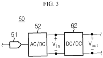
- FIG. 3 is an exemplary diagram showing the configuration of the battery charger according to the present disclosure
- FIG. 4 is an exemplary diagram showing the configuration of the DC-DC converter of FIG. 3 .
- the battery charger 50 is provided to be connectable to two terminals of the battery B.
- the battery charger 50 includes the DC-DC converter 62.
- the battery charger 50 may further include a charger plug 51 and an AC-DC converter 52.
- the AC-DC converter 52 is configured to convert the AC power from an AC charging state (not shown) connected to the charger plug 51 to DC power having a predetermined voltage level.
- the DC-DC converter 62 is configured to generate the charge power for the battery B using the DC power from the AC-DC converter 52 or a DC charging station (not shown).
- the DC-DC converter 62 is a buck converter which steps down the input voltage V in to generate the output voltage V out lower than the input voltage V in .
- the DC-DC converter 62 includes a voltage input terminal N i , a voltage output terminal N o , a buck switch SW B , a buck inductor L B , a buck capacitor C B , a buck diode D B and a protection circuit 70.
- the protection circuit 70 may be referred to as a 'passive snubber'.
- the input voltage V in from the AC-DC converter 52 or the DC charging station may be supplied between the voltage input terminal N i and the ground.
- the battery B may be connected between the voltage output terminal N o and the ground.
- the buck switch SW B is connected between the voltage input terminal N i and the first node N 1 .
- the on-off control of the buck switch SW B is performed in response to the switching signal S 2 from the switch driver 150.
- the buck switch SW B may be a well-known switching device, for example, MOSFET.
- the switching cycle and the duty cycle of the switching signal S 2 are T S and D, respectively, the buck switch SW B is kept in the ON state for a first period of time of T S ⁇ D, and is kept in the OFF state for a second period of time of T S ⁇ (1-D).
- the sum of the first period of time and the second period of time is equal to the switching cycle Ts.
- the buck inductor L B is connected between the first node N 1 and the voltage output terminal N o .
- the buck inductor L B is charged by the input current from the first node N 1 for the first period of time.
- the energy charged in the buck inductor L B for the first period of time is supplied to the voltage output terminal N o for the second period of time.
- the equilibrium between the energy charged in the buck inductor L B for the first period of time and the energy discharged from the buck inductor L B for the second period of time may be referred to 'steady state' of the DC-DC converter 62.
- the buck capacitor C B is connected between the voltage output terminal N o and the ground.
- the buck capacitor C B is provided to suppress the ripple of the output voltage V out supplied between the voltage output terminal N o and the ground.
- the buck diode D B is connected between a second node N 2 and the ground. Specifically, the anode and the cathode of the buck diode D B are connected to the ground and the second node N 2 , respectively.
- the potential of the second node N 2 is higher than the ground potential, and the buck diode D B gets into the OFF state.
- the potential of the second node N 2 is lower than the ground potential, and the buck diode D B gets into the OFF state. While the buck diode D B is in the ON state, the electric current from the ground to the second node N 2 flows through the buck diode D B .
- the protection circuit 70 is connected to the first node N 1 , the second node N 2 and the ground.
- the protection circuit 70 is configured to supply a protection voltage between the first node N 1 and the ground when the buck switch SW B is switched from any one of the ON state and the OFF state to the other by the switching signal S 2 . Since the voltage stress of the buck switch SW B is a voltage difference between the voltage input terminal N i and the first node N 1 , the voltage stress of the buck switch SW B is reduced below the input voltage V in supplied between the voltage input terminal N i and the ground by the protection voltage.
- the protection circuit 70 includes a first protection capacitor C P1 , a second protection capacitor C P2 , a protection inductor L P and a protection diode D P .
- Isw denotes the electric current flowing through the buck switch SW B
- I LB denotes the electric current flowing through the buck inductor L B
- I LP denotes the electric current flowing through the protection inductor L P
- I CP1 denotes the electric current flowing through the first protection capacitor C P1
- I CP2 denotes the electric current flowing through the second protection capacitor C P2
- I DB denotes the electric current flowing through the buck diode D B
- I DP denotes the electric current flowing through the protection diode D P
- V SW denotes the voltage stress of the buck switch SW B .
- the first protection capacitor C P1 is connected between the first node N 1 and the second node N 2 .
- the second protection capacitor C P2 is connected between a third node N 3 and the ground.
- the first protection capacitor C P1 and the second protection capacitor C P2 reduce the magnitude of the voltage stress SW B of the buck switch SW B by supplying the protection voltage between the first node N 1 and the ground when the buck switch SW B is switched between the ON state and the OFF state.
- the protection inductor L P is connected between the second node N 2 and the third node N 3 .
- the protection inductor L P is provided to suppress a sharp change in the electric current I CP1 of the first protection capacitor C P1 and the electric current I CP2 of the second protection capacitor C P2 during the charge and discharge of the first protection capacitor C P1 and the second protection capacitor C P2 .
- the protection diode D P is connected between the first node N 1 and the third node N 3 . Specifically, the anode and the cathode of the protection diode D P are connected to the third node N 3 and the first node N 1 , respectively.
- the protection diode D P gets into the ON state. While the protection diode D P is in the ON state, the electric current I DP from the third node N 3 to the first node N 1 flows through the protection diode D P .
- the protection diode D P gets into the OFF state. While the protection diode D P is in the OFF state, the flow of the electric current between the first node N 1 and the third node N 3 is interrupted.
- FIG. 5 is a schematic diagram showing a current waveform of each device and a voltage waveform of the buck switch over a single switching cycle during the operation of the DC-DC converter 62 of FIG. 4 in a steady state.
- a single switch cycle may be divided into four continuous operation modes according to the state of the buck switch SW B and the direction of the electric current of the protection inductor L P .
- the electric current I CP1 is equal to the electric current I CP2
- the electric current I DP is equal to the electric current I DB
- the waveform of the electric current I CP2 and the waveform of the electric current I DB are omitted from FIG. 5 .
- the first operation mode is an operation mode from the time at which the buck switch SW B is switched from the OFF state to the ON state to the time at which the electric current I LP reaches 0 A from a negative value.
- the electric current I LP having the negative value in the first operation mode represents that the first protection capacitor C P1 ) and the second protection capacitor C P2 are discharged in the first operation mode.
- the second operation mode is an operation mode in which the electric current I LP gradually rises from 0A while the buck switch SW B is kept in the ON state.
- the electric current I LP having a positive value that is larger than 0 A in the second operation mode represents that the first protection capacitor C P1 and the second protection capacitor C P2 are charged in the second operation mode.
- the buck diode D B and the protection diode D P are in the OFF state. Accordingly, a voltage of a series circuit of the first protection capacitor C P1 , the protection inductor L P and the second protection capacitor C P2 is equal to the input voltage V in .
- the third operation mode is an operation mode from the time at which the buck switch SW B is switched from the ON state to the OFF state to the time at which the electric current I LP reaches 0 A from a positive value.
- the fourth operation mode is an operation mode in which the electric current I LP gradually reduces from 0A while the buck switch SW B is kept in the OFF state.
- the buck diode D B and the protection diode D P are in the ON state, and thus a series circuit of the first protection capacitor C P1 and the buck diode D B supplies the protection voltage that is larger than 0V between the first node N 1 and the ground. That is, the protection voltage may be equal to a voltage across the series circuit of the first protection capacitor C P1 and the buck diode D B .
- Equation 5 is derived from Equations 1 and 3
- Equation 6 is derived from Equations 2 and 4.
- Equation 5 D 1 + D ⁇ V in
- Gv is a voltage gain of the DC-DC converter 62.
- the duty cycle D is between 0 ⁇ 1. Accordingly, the voltage stress Vsw of the DC-DC converter 62 reduces by 1/(1+D) of the input voltage V in by the protection circuit 70. That is, in the conventional DC-DC converter shown in FIG. 1 , voltage stress having the same magnitude as the input voltage V in is supplied to the buck switch SW B irrespective of the duty cycle D, while in the DC-DC converter 62 according to the present disclosure, the voltage stress Vsw that is smaller than the input voltage V in is supplied to the buck switch SW B . Additionally, the DC-DC converter 62 according to the present disclosure reduces in voltage stress Vsw of the buck switch SW B with the increasing duty cycle D.
- the control unit 140 may increase the duty cycle D by a predetermined ratio at a preset time interval using the DC-DC converter 62 during the charge of the battery B.
Landscapes
- Engineering & Computer Science (AREA)
- Power Engineering (AREA)
- Transportation (AREA)
- Mechanical Engineering (AREA)
- Dc-Dc Converters (AREA)
Applications Claiming Priority (2)
| Application Number | Priority Date | Filing Date | Title |
|---|---|---|---|
| KR1020200111845A KR20220030087A (ko) | 2020-09-02 | 2020-09-02 | 보호 회로, dc-dc 컨버터, 배터리 충전기 및 전기 차량 |
| PCT/KR2021/011403 WO2022050630A1 (fr) | 2020-09-02 | 2021-08-25 | Circuit de protection, convertisseur cc-cc, chargeur de batterie et véhicule électrique |
Publications (2)
| Publication Number | Publication Date |
|---|---|
| EP4170882A1 true EP4170882A1 (fr) | 2023-04-26 |
| EP4170882A4 EP4170882A4 (fr) | 2023-11-29 |
Family
ID=80491145
Family Applications (1)
| Application Number | Title | Priority Date | Filing Date |
|---|---|---|---|
| EP21864590.1A Pending EP4170882A4 (fr) | 2020-09-02 | 2021-08-25 | Circuit de protection, convertisseur cc-cc, chargeur de batterie et véhicule électrique |
Country Status (6)
| Country | Link |
|---|---|
| US (1) | US20240030805A1 (fr) |
| EP (1) | EP4170882A4 (fr) |
| JP (1) | JP2023527810A (fr) |
| KR (1) | KR20220030087A (fr) |
| CN (1) | CN115702546A (fr) |
| WO (1) | WO2022050630A1 (fr) |
Family Cites Families (9)
| Publication number | Priority date | Publication date | Assignee | Title |
|---|---|---|---|---|
| JP3888066B2 (ja) * | 2001-01-31 | 2007-02-28 | 松下電工株式会社 | 無電極放電灯点灯装置 |
| US7285919B2 (en) * | 2001-06-22 | 2007-10-23 | Lutron Electronics Co., Inc. | Electronic ballast having improved power factor and total harmonic distortion |
| JP2007082332A (ja) * | 2005-09-14 | 2007-03-29 | Daikin Ind Ltd | Dc−dcコンバータ及びその制御方法 |
| KR101022772B1 (ko) * | 2008-12-30 | 2011-03-17 | 한국전기연구원 | 연료전지용 전력변환장치. |
| JP2013135570A (ja) * | 2011-12-27 | 2013-07-08 | Denso Corp | Dc−dcコンバータ |
| US9413257B2 (en) * | 2012-01-20 | 2016-08-09 | The Ohio State University | Enhanced flyback converter |
| JP6986811B2 (ja) * | 2018-08-14 | 2021-12-22 | 正一 田中 | 直流電源 |
| CN109742944B (zh) * | 2018-12-17 | 2020-08-28 | 北京交通大学 | 基于Buck-Boost型高增益升压变换器 |
| KR20200111845A (ko) | 2019-03-19 | 2020-10-05 | 삼성디스플레이 주식회사 | 유기 발광 표시 장치 |
-
2020
- 2020-09-02 KR KR1020200111845A patent/KR20220030087A/ko not_active Application Discontinuation
-
2021
- 2021-08-25 WO PCT/KR2021/011403 patent/WO2022050630A1/fr active Application Filing
- 2021-08-25 EP EP21864590.1A patent/EP4170882A4/fr active Pending
- 2021-08-25 US US18/024,078 patent/US20240030805A1/en active Pending
- 2021-08-25 JP JP2022572424A patent/JP2023527810A/ja active Pending
- 2021-08-25 CN CN202180043927.1A patent/CN115702546A/zh active Pending
Also Published As
| Publication number | Publication date |
|---|---|
| KR20220030087A (ko) | 2022-03-10 |
| WO2022050630A1 (fr) | 2022-03-10 |
| EP4170882A4 (fr) | 2023-11-29 |
| US20240030805A1 (en) | 2024-01-25 |
| JP2023527810A (ja) | 2023-06-30 |
| CN115702546A (zh) | 2023-02-14 |
Similar Documents
| Publication | Publication Date | Title |
|---|---|---|
| EP3637532B1 (fr) | Dispositif d'activation de bms, et bms et bloc-batterie comprenant ledit dispositif | |
| KR101677679B1 (ko) | 2차 전지 스택을 위한 전력 관리 회로 | |
| US10141551B2 (en) | Battery system | |
| JP5839210B2 (ja) | バッテリー充電装置及び方法 | |
| JP5858306B2 (ja) | バッテリーパック連結制御装置及び方法 | |
| TWI246215B (en) | Battery pack and a battery charging/discharging circuit incorporating the same | |
| US9673638B2 (en) | Apparatus and method for a switching power converter | |
| GB2479812A (en) | PSU whereby load current is jointly provided by a rechargeable battery and an adapter in a boost power mode. | |
| TWI804503B (zh) | 蓄電系統以及電氣機器 | |
| EP2891944B1 (fr) | Configuration d'empilement de batteries dans un système d'alimentation multi-batterie | |
| CN109964381A (zh) | 混合电池组系统 | |
| US20210242771A1 (en) | Multi-mode dc-to-dc power converter | |
| US20210376643A1 (en) | Adaptive Power Systems and Techniques | |
| EP1717926A2 (fr) | Chargeur de batterie | |
| EP4105069A1 (fr) | Dispositif de gestion de charge, procédé de gestion de charge et véhicule électrique | |
| EP3678280B1 (fr) | Circuit d'alimentation pour la transmission d'énergie entre une batterie et un condensateur de lissage, système de gestion de batterie et bloc-batterie | |
| US20200119563A1 (en) | Battery management | |
| EP4170882A1 (fr) | Circuit de protection, convertisseur cc-cc, chargeur de batterie et véhicule électrique | |
| EP4068562A1 (fr) | Système de gestion de batterie, procédé de gestion de batterie, bloc-batterie et véhicule électrique | |
| CN215528640U (zh) | 一种充电电路 | |
| KR20240025555A (ko) | 배터리 팩의 양방향 적응형 단자 전압(batv) | |
| CN114938061A (zh) | 充放电电路和终端设备 |
Legal Events
| Date | Code | Title | Description |
|---|---|---|---|
| STAA | Information on the status of an ep patent application or granted ep patent |
Free format text: STATUS: THE INTERNATIONAL PUBLICATION HAS BEEN MADE |
|
| PUAI | Public reference made under article 153(3) epc to a published international application that has entered the european phase |
Free format text: ORIGINAL CODE: 0009012 |
|
| STAA | Information on the status of an ep patent application or granted ep patent |
Free format text: STATUS: REQUEST FOR EXAMINATION WAS MADE |
|
| 17P | Request for examination filed |
Effective date: 20230123 |
|
| AK | Designated contracting states |
Kind code of ref document: A1 Designated state(s): AL AT BE BG CH CY CZ DE DK EE ES FI FR GB GR HR HU IE IS IT LI LT LU LV MC MK MT NL NO PL PT RO RS SE SI SK SM TR |
|
| REG | Reference to a national code |
Ref country code: DE Ref legal event code: R079 Free format text: PREVIOUS MAIN CLASS: H02M0001340000 Ipc: H02M0003156000 |
|
| A4 | Supplementary search report drawn up and despatched |
Effective date: 20231030 |
|
| RIC1 | Information provided on ipc code assigned before grant |
Ipc: B60L 53/20 20190101ALI20231024BHEP Ipc: H02M 1/00 20060101ALI20231024BHEP Ipc: H02M 1/34 20070101ALI20231024BHEP Ipc: H02M 1/32 20070101ALI20231024BHEP Ipc: H02M 3/156 20060101AFI20231024BHEP |
|
| DAV | Request for validation of the european patent (deleted) | ||
| DAX | Request for extension of the european patent (deleted) |