EP4170690B1 - Electrical steel sheet, laminated core and rotating electric machine - Google Patents
Electrical steel sheet, laminated core and rotating electric machine Download PDFInfo
- Publication number
- EP4170690B1 EP4170690B1 EP21826256.6A EP21826256A EP4170690B1 EP 4170690 B1 EP4170690 B1 EP 4170690B1 EP 21826256 A EP21826256 A EP 21826256A EP 4170690 B1 EP4170690 B1 EP 4170690B1
- Authority
- EP
- European Patent Office
- Prior art keywords
- electrical steel
- steel sheet
- temperature
- insulation coating
- logarithmic decrement
- Prior art date
- Legal status (The legal status is an assumption and is not a legal conclusion. Google has not performed a legal analysis and makes no representation as to the accuracy of the status listed.)
- Active
Links
Images


Classifications
-
- H—ELECTRICITY
- H01—ELECTRIC ELEMENTS
- H01F—MAGNETS; INDUCTANCES; TRANSFORMERS; SELECTION OF MATERIALS FOR THEIR MAGNETIC PROPERTIES
- H01F27/00—Details of transformers or inductances, in general
- H01F27/24—Magnetic cores
- H01F27/245—Magnetic cores made from sheets, e.g. grain-oriented
-
- B—PERFORMING OPERATIONS; TRANSPORTING
- B05—SPRAYING OR ATOMISING IN GENERAL; APPLYING FLUENT MATERIALS TO SURFACES, IN GENERAL
- B05D—PROCESSES FOR APPLYING FLUENT MATERIALS TO SURFACES, IN GENERAL
- B05D7/00—Processes, other than flocking, specially adapted for applying liquids or other fluent materials to particular surfaces or for applying particular liquids or other fluent materials
- B05D7/14—Processes, other than flocking, specially adapted for applying liquids or other fluent materials to particular surfaces or for applying particular liquids or other fluent materials to metal, e.g. car bodies
- B05D7/148—Processes, other than flocking, specially adapted for applying liquids or other fluent materials to particular surfaces or for applying particular liquids or other fluent materials to metal, e.g. car bodies using epoxy-polyolefin systems in mono- or multilayers
-
- B—PERFORMING OPERATIONS; TRANSPORTING
- B32—LAYERED PRODUCTS
- B32B—LAYERED PRODUCTS, i.e. PRODUCTS BUILT-UP OF STRATA OF FLAT OR NON-FLAT, e.g. CELLULAR OR HONEYCOMB, FORM
- B32B15/00—Layered products comprising a layer of metal
- B32B15/04—Layered products comprising a layer of metal comprising metal as the main or only constituent of a layer, which is next to another layer of the same or of a different material
- B32B15/043—Layered products comprising a layer of metal comprising metal as the main or only constituent of a layer, which is next to another layer of the same or of a different material of metal
-
- B—PERFORMING OPERATIONS; TRANSPORTING
- B32—LAYERED PRODUCTS
- B32B—LAYERED PRODUCTS, i.e. PRODUCTS BUILT-UP OF STRATA OF FLAT OR NON-FLAT, e.g. CELLULAR OR HONEYCOMB, FORM
- B32B15/00—Layered products comprising a layer of metal
- B32B15/18—Layered products comprising a layer of metal comprising iron or steel
-
- B—PERFORMING OPERATIONS; TRANSPORTING
- B32—LAYERED PRODUCTS
- B32B—LAYERED PRODUCTS, i.e. PRODUCTS BUILT-UP OF STRATA OF FLAT OR NON-FLAT, e.g. CELLULAR OR HONEYCOMB, FORM
- B32B7/00—Layered products characterised by the relation between layers; Layered products characterised by the relative orientation of features between layers, or by the relative values of a measurable parameter between layers, i.e. products comprising layers having different physical, chemical or physicochemical properties; Layered products characterised by the interconnection of layers
- B32B7/04—Interconnection of layers
- B32B7/12—Interconnection of layers using interposed adhesives or interposed materials with bonding properties
-
- C—CHEMISTRY; METALLURGY
- C23—COATING METALLIC MATERIAL; COATING MATERIAL WITH METALLIC MATERIAL; CHEMICAL SURFACE TREATMENT; DIFFUSION TREATMENT OF METALLIC MATERIAL; COATING BY VACUUM EVAPORATION, BY SPUTTERING, BY ION IMPLANTATION OR BY CHEMICAL VAPOUR DEPOSITION, IN GENERAL; INHIBITING CORROSION OF METALLIC MATERIAL OR INCRUSTATION IN GENERAL
- C23C—COATING METALLIC MATERIAL; COATING MATERIAL WITH METALLIC MATERIAL; SURFACE TREATMENT OF METALLIC MATERIAL BY DIFFUSION INTO THE SURFACE, BY CHEMICAL CONVERSION OR SUBSTITUTION; COATING BY VACUUM EVAPORATION, BY SPUTTERING, BY ION IMPLANTATION OR BY CHEMICAL VAPOUR DEPOSITION, IN GENERAL
- C23C22/00—Chemical surface treatment of metallic material by reaction of the surface with a reactive liquid, leaving reaction products of surface material in the coating, e.g. conversion coatings, passivation of metals
- C23C22/05—Chemical surface treatment of metallic material by reaction of the surface with a reactive liquid, leaving reaction products of surface material in the coating, e.g. conversion coatings, passivation of metals using aqueous solutions
- C23C22/06—Chemical surface treatment of metallic material by reaction of the surface with a reactive liquid, leaving reaction products of surface material in the coating, e.g. conversion coatings, passivation of metals using aqueous solutions using aqueous acidic solutions with pH less than 6
- C23C22/07—Chemical surface treatment of metallic material by reaction of the surface with a reactive liquid, leaving reaction products of surface material in the coating, e.g. conversion coatings, passivation of metals using aqueous solutions using aqueous acidic solutions with pH less than 6 containing phosphates
-
- H—ELECTRICITY
- H01—ELECTRIC ELEMENTS
- H01F—MAGNETS; INDUCTANCES; TRANSFORMERS; SELECTION OF MATERIALS FOR THEIR MAGNETIC PROPERTIES
- H01F1/00—Magnets or magnetic bodies characterised by the magnetic materials therefor; Selection of materials for their magnetic properties
- H01F1/01—Magnets or magnetic bodies characterised by the magnetic materials therefor; Selection of materials for their magnetic properties of inorganic materials
- H01F1/03—Magnets or magnetic bodies characterised by the magnetic materials therefor; Selection of materials for their magnetic properties of inorganic materials characterised by their coercivity
- H01F1/12—Magnets or magnetic bodies characterised by the magnetic materials therefor; Selection of materials for their magnetic properties of inorganic materials characterised by their coercivity of soft-magnetic materials
- H01F1/14—Magnets or magnetic bodies characterised by the magnetic materials therefor; Selection of materials for their magnetic properties of inorganic materials characterised by their coercivity of soft-magnetic materials metals or alloys
- H01F1/147—Alloys characterised by their composition
-
- H—ELECTRICITY
- H01—ELECTRIC ELEMENTS
- H01F—MAGNETS; INDUCTANCES; TRANSFORMERS; SELECTION OF MATERIALS FOR THEIR MAGNETIC PROPERTIES
- H01F1/00—Magnets or magnetic bodies characterised by the magnetic materials therefor; Selection of materials for their magnetic properties
- H01F1/01—Magnets or magnetic bodies characterised by the magnetic materials therefor; Selection of materials for their magnetic properties of inorganic materials
- H01F1/03—Magnets or magnetic bodies characterised by the magnetic materials therefor; Selection of materials for their magnetic properties of inorganic materials characterised by their coercivity
- H01F1/12—Magnets or magnetic bodies characterised by the magnetic materials therefor; Selection of materials for their magnetic properties of inorganic materials characterised by their coercivity of soft-magnetic materials
- H01F1/14—Magnets or magnetic bodies characterised by the magnetic materials therefor; Selection of materials for their magnetic properties of inorganic materials characterised by their coercivity of soft-magnetic materials metals or alloys
- H01F1/16—Magnets or magnetic bodies characterised by the magnetic materials therefor; Selection of materials for their magnetic properties of inorganic materials characterised by their coercivity of soft-magnetic materials metals or alloys in the form of sheets
- H01F1/18—Magnets or magnetic bodies characterised by the magnetic materials therefor; Selection of materials for their magnetic properties of inorganic materials characterised by their coercivity of soft-magnetic materials metals or alloys in the form of sheets with insulating coating
-
- H—ELECTRICITY
- H01—ELECTRIC ELEMENTS
- H01F—MAGNETS; INDUCTANCES; TRANSFORMERS; SELECTION OF MATERIALS FOR THEIR MAGNETIC PROPERTIES
- H01F27/00—Details of transformers or inductances, in general
- H01F27/24—Magnetic cores
-
- H—ELECTRICITY
- H01—ELECTRIC ELEMENTS
- H01F—MAGNETS; INDUCTANCES; TRANSFORMERS; SELECTION OF MATERIALS FOR THEIR MAGNETIC PROPERTIES
- H01F3/00—Cores, Yokes, or armatures
- H01F3/02—Cores, Yokes, or armatures made from sheets
-
- H—ELECTRICITY
- H01—ELECTRIC ELEMENTS
- H01F—MAGNETS; INDUCTANCES; TRANSFORMERS; SELECTION OF MATERIALS FOR THEIR MAGNETIC PROPERTIES
- H01F41/00—Apparatus or processes specially adapted for manufacturing or assembling magnets, inductances or transformers; Apparatus or processes specially adapted for manufacturing materials characterised by their magnetic properties
- H01F41/02—Apparatus or processes specially adapted for manufacturing or assembling magnets, inductances or transformers; Apparatus or processes specially adapted for manufacturing materials characterised by their magnetic properties for manufacturing cores, coils, or magnets
- H01F41/0206—Manufacturing of magnetic cores by mechanical means
- H01F41/0233—Manufacturing of magnetic circuits made from sheets
-
- H—ELECTRICITY
- H02—GENERATION; CONVERSION OR DISTRIBUTION OF ELECTRIC POWER
- H02K—DYNAMO-ELECTRIC MACHINES
- H02K1/00—Details of the magnetic circuit
- H02K1/02—Details of the magnetic circuit characterised by the magnetic material
-
- H—ELECTRICITY
- H02—GENERATION; CONVERSION OR DISTRIBUTION OF ELECTRIC POWER
- H02K—DYNAMO-ELECTRIC MACHINES
- H02K1/00—Details of the magnetic circuit
- H02K1/04—Details of the magnetic circuit characterised by the material used for insulating the magnetic circuit or parts thereof
-
- B—PERFORMING OPERATIONS; TRANSPORTING
- B05—SPRAYING OR ATOMISING IN GENERAL; APPLYING FLUENT MATERIALS TO SURFACES, IN GENERAL
- B05D—PROCESSES FOR APPLYING FLUENT MATERIALS TO SURFACES, IN GENERAL
- B05D2202/00—Metallic substrate
- B05D2202/10—Metallic substrate based on Fe
-
- B—PERFORMING OPERATIONS; TRANSPORTING
- B05—SPRAYING OR ATOMISING IN GENERAL; APPLYING FLUENT MATERIALS TO SURFACES, IN GENERAL
- B05D—PROCESSES FOR APPLYING FLUENT MATERIALS TO SURFACES, IN GENERAL
- B05D2504/00—Epoxy polymers
-
- B—PERFORMING OPERATIONS; TRANSPORTING
- B05—SPRAYING OR ATOMISING IN GENERAL; APPLYING FLUENT MATERIALS TO SURFACES, IN GENERAL
- B05D—PROCESSES FOR APPLYING FLUENT MATERIALS TO SURFACES, IN GENERAL
- B05D3/00—Pretreatment of surfaces to which liquids or other fluent materials are to be applied; After-treatment of applied coatings, e.g. intermediate treating of an applied coating preparatory to subsequent applications of liquids or other fluent materials
- B05D3/02—Pretreatment of surfaces to which liquids or other fluent materials are to be applied; After-treatment of applied coatings, e.g. intermediate treating of an applied coating preparatory to subsequent applications of liquids or other fluent materials by baking
- B05D3/0254—After-treatment
-
- B—PERFORMING OPERATIONS; TRANSPORTING
- B05—SPRAYING OR ATOMISING IN GENERAL; APPLYING FLUENT MATERIALS TO SURFACES, IN GENERAL
- B05D—PROCESSES FOR APPLYING FLUENT MATERIALS TO SURFACES, IN GENERAL
- B05D5/00—Processes for applying liquids or other fluent materials to surfaces to obtain special surface effects, finishes or structures
- B05D5/10—Processes for applying liquids or other fluent materials to surfaces to obtain special surface effects, finishes or structures to obtain an adhesive surface
-
- B—PERFORMING OPERATIONS; TRANSPORTING
- B05—SPRAYING OR ATOMISING IN GENERAL; APPLYING FLUENT MATERIALS TO SURFACES, IN GENERAL
- B05D—PROCESSES FOR APPLYING FLUENT MATERIALS TO SURFACES, IN GENERAL
- B05D5/00—Processes for applying liquids or other fluent materials to surfaces to obtain special surface effects, finishes or structures
- B05D5/12—Processes for applying liquids or other fluent materials to surfaces to obtain special surface effects, finishes or structures to obtain a coating with specific electrical properties
-
- B—PERFORMING OPERATIONS; TRANSPORTING
- B05—SPRAYING OR ATOMISING IN GENERAL; APPLYING FLUENT MATERIALS TO SURFACES, IN GENERAL
- B05D—PROCESSES FOR APPLYING FLUENT MATERIALS TO SURFACES, IN GENERAL
- B05D7/00—Processes, other than flocking, specially adapted for applying liquids or other fluent materials to particular surfaces or for applying particular liquids or other fluent materials
- B05D7/14—Processes, other than flocking, specially adapted for applying liquids or other fluent materials to particular surfaces or for applying particular liquids or other fluent materials to metal, e.g. car bodies
-
- B—PERFORMING OPERATIONS; TRANSPORTING
- B32—LAYERED PRODUCTS
- B32B—LAYERED PRODUCTS, i.e. PRODUCTS BUILT-UP OF STRATA OF FLAT OR NON-FLAT, e.g. CELLULAR OR HONEYCOMB, FORM
- B32B2255/00—Coating on the layer surface
- B32B2255/06—Coating on the layer surface on metal layer
-
- B—PERFORMING OPERATIONS; TRANSPORTING
- B32—LAYERED PRODUCTS
- B32B—LAYERED PRODUCTS, i.e. PRODUCTS BUILT-UP OF STRATA OF FLAT OR NON-FLAT, e.g. CELLULAR OR HONEYCOMB, FORM
- B32B2255/00—Coating on the layer surface
- B32B2255/26—Polymeric coating
-
- B—PERFORMING OPERATIONS; TRANSPORTING
- B32—LAYERED PRODUCTS
- B32B—LAYERED PRODUCTS, i.e. PRODUCTS BUILT-UP OF STRATA OF FLAT OR NON-FLAT, e.g. CELLULAR OR HONEYCOMB, FORM
- B32B2307/00—Properties of the layers or laminate
- B32B2307/10—Properties of the layers or laminate having particular acoustical properties
- B32B2307/102—Insulating
-
- B—PERFORMING OPERATIONS; TRANSPORTING
- B32—LAYERED PRODUCTS
- B32B—LAYERED PRODUCTS, i.e. PRODUCTS BUILT-UP OF STRATA OF FLAT OR NON-FLAT, e.g. CELLULAR OR HONEYCOMB, FORM
- B32B2603/00—Vanes, blades, propellers, rotors with blades
-
- C—CHEMISTRY; METALLURGY
- C22—METALLURGY; FERROUS OR NON-FERROUS ALLOYS; TREATMENT OF ALLOYS OR NON-FERROUS METALS
- C22C—ALLOYS
- C22C38/00—Ferrous alloys, e.g. steel alloys
- C22C38/02—Ferrous alloys, e.g. steel alloys containing silicon
-
- C—CHEMISTRY; METALLURGY
- C22—METALLURGY; FERROUS OR NON-FERROUS ALLOYS; TREATMENT OF ALLOYS OR NON-FERROUS METALS
- C22C—ALLOYS
- C22C38/00—Ferrous alloys, e.g. steel alloys
- C22C38/04—Ferrous alloys, e.g. steel alloys containing manganese
-
- C—CHEMISTRY; METALLURGY
- C22—METALLURGY; FERROUS OR NON-FERROUS ALLOYS; TREATMENT OF ALLOYS OR NON-FERROUS METALS
- C22C—ALLOYS
- C22C38/00—Ferrous alloys, e.g. steel alloys
- C22C38/06—Ferrous alloys, e.g. steel alloys containing aluminium
-
- H—ELECTRICITY
- H01—ELECTRIC ELEMENTS
- H01F—MAGNETS; INDUCTANCES; TRANSFORMERS; SELECTION OF MATERIALS FOR THEIR MAGNETIC PROPERTIES
- H01F27/00—Details of transformers or inductances, in general
- H01F27/33—Arrangements for noise damping
Definitions
- the present invention relates to an electrical steel sheet, a laminated core and a rotating electric machine.
- Priority is claimed on Japanese Patent Application No. 2020-104232, filed June 17, 2020 .
- a core iron core
- a laminated core in which a plurality of electrical steel sheets are bonded to each other and laminated
- Caulking and welding are known as methods of bonding electrical steel sheets to each other.
- magnetic properties of electrical steel sheets may deteriorate due to mechanical stress and thermal stress during processing as well as short circuiting between layers, and the performance of the laminated core may deteriorate.
- Patent Documents 1 and 2 disclose electrical steel sheets in which the peak temperature of the logarithmic decrement of the film is controlled.
- Patent Document 3 discloses a laminate electrical steel sheet in which the maximum value of the logarithmic decrement of the adhesive layer (insulation coating) is controlled.
- Patent Document 4 discloses a composition for adhesion layer that is used for obtaining a multi-layered surface treatment steel sheet in which an adhesion layer is formed onto at least one surface of the steel sheet, and an upper layer and/or an intermediate layer which has a design and which contains a rust preventive pigment and/or a colored pigment is formed onto the adhesion layer; the composition including a cationic urethane resin and a silicon compound in an aqueous medium, and the ratio between the temperature at which the logarithmic decrement for the mixture of the cationic urethane resin and the silicon compound in the rigid-body pendulum type free damped vibration method shows the maximum value and the temperature at which the logarithmic decrement for the cationic urethane resin alone in the rigid-body pendulum type free damped vibration method shows the maximum value is in the range of 1.2 to 3.0.
- Patent Document 5 discloses a flat rolled magnetic steel sheet or strip having its surface coated for bonding by heating and pressurization, which flat rolled magnetic steel sheet or strip, even at thin coating, permits bonding over the whole surface of steel sheet and reduces bonding strength lowering.
- a flat rolled magnetic steel sheet or strip having its surface coated for bonding comprising a flat rolled magnetic steel sheet or strip and, superimposed on a surface thereof, an insulating film exhibiting bonding capability upon application of heat and pressure, characterized in that the insulating film is composed of a mixture of an epoxy resin of 80 to 150°C glass transition temperature (Tg) or modification product thereof and an epoxy resin hardening agent wherein a particulate polymer of 0.01 to 0.5 ⁇ m particle diameter is dispersed.
- Tg glass transition temperature
- the flat rolled magnetic steel sheet or strip having its surface coated for bonding is further characterized in that the Tg of the particulate polymer is in the range of 10 to 80°C, and still further in that the particulate polymer is
- An object of the present invention is to provide an electrical steel sheet which enables production of a laminated core with improved core performance in one or more of workability during punching of an electrical steel sheet, lamination accuracy, noise reduction by minimizing uneven curing, and achievement of both a lamination factor and adhesive strength, and a laminated core using the electrical steel sheet and a rotating electric machine.
- the present invention is defined in claim 1 and has the following configuration:
- An object of the present invention is to provide an electrical steel sheet which enables production of a laminated core with improved core performance in one or more of improvement in workability during punching of an electrical steel sheet and lamination accuracy, noise reduction by minimizing uneven curing, and achievement of both a lamination factor and adhesive strength and a laminated core using the electrical steel sheet and a rotating electric machine.
- a laminated core according to one embodiment of the present invention a rotating electric machine including the laminated core, and a material forming the laminated core will be described with reference to the drawings.
- an electric motor specifically, an AC electric motor, more specifically, a synchronous electric motor, and still more specifically, a permanent magnet field type electric motor will be described as an example.
- This type of electric motor is suitably used for, for example, an electric automobile.
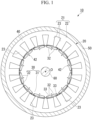
- a rotating electric machine 10 includes a stator 20, a rotor 30, a case 50, and a rotating shaft 60.
- the stator 20 and the rotor 30 are accommodated in the case 50.
- the stator 20 is fixed into the case 50.
- the rotating electric machine 10 an inner rotor type machine in which the rotor 30 is positioned inside the stator 20 in the radial direction is used.
- an outer rotor type machine in which the rotor 30 is positioned outside the stator 20 may be used.
- the rotating electric machine 10 is a 12-pole and 18-slot three-phase AC motor.
- the number of poles, the number of slots, the number of phases, and the like can be appropriately changed.
- the rotating electric machine 10 can rotate at a rotational speed of 1,000 rpm by applying, for example, an excitation current having an effective value of 10 A and a frequency of 100 Hz to each phase.
- the stator 20 includes an adhesive laminated core for a stator (hereinafter referred to as a stator core) 21 and a winding (not shown).
- the stator core 21 includes a circular core back part 22 and a plurality of teeth parts 23.
- the center axis O direction of the stator core 21 (or the core back part 22) will be referred to as an axial direction
- the radial direction (direction orthogonal to the center axis O) of the stator core 21 (or the core back part 22) will be referred to as a radial direction
- the circumferential direction (direction around the center axis O) of the stator core 21 (or the core back part 22) will be referred to as a circumferential direction.
- the core back part 22 is formed in an annular shape in a plan view of the stator 20 when viewed from the axial direction.
- the plurality of teeth parts 23 protrudes from the inner peripheral of the core back part 22 in a radially inward direction (toward the center axis O of the core back part 22 in the radial direction).
- the plurality of teeth parts 23 are arranged at equal angular intervals in the circumferential direction.
- 18 teeth parts 23 are provided at every 20 degrees in central angles centered on the center axis O.
- the plurality of teeth parts 23 are formed so that they have the same shape and the same size. Therefore, the plurality of teeth parts 23 have the same thickness size.
- the winding is wound around the teeth parts 23.
- the winding may be centralized winding or distributed winding.
- the rotor core 31 is formed in a circular (annular) shape and arranged coaxially with the stator 20.
- the rotating shaft 60 is arranged in the rotor core 31.
- the rotating shaft 60 is fixed to the rotor core 31.
- the plurality of permanent magnets 32 are fixed to the rotor core 31.
- a pair of permanent magnets 32 form one magnetic pole.
- the plurality of sets of permanent magnets 32 are arranged at equal angular intervals in the circumferential direction.
- 12 sets (24 in total) of permanent magnets 32 are provided at every 30 degrees in central angles centered on the center axis O.
- both the stator core 21 and the rotor core 31 are laminated cores.
- the stator core 21 is formed by laminating a plurality of electrical steel sheets 40 in the lamination direction.
- the lamination thickness (total length along the center axis O) of each of the stator core 21 and the rotor core 31 is, for example, 50.0 mm.
- the outer diameter of the stator core 21 is, for example, 250.0 mm.
- the inner diameter of the stator core 21 is, for example, 165.0 mm.
- the outer diameter of the rotor core 31 is, for example, 163.0 mm.
- the inner diameter of the rotor core 31 is, for example, 30.0 mm.
- these values are examples, and the lamination thickness, the outer diameter and the inner diameter of the stator core 21, and the lamination thickness, the outer diameter and the inner diameter of the rotor core 31 are not limited to these values.
- the inner diameter of the stator core 21 is based on the tip part of the teeth part 23 in the stator core 21. That is, the inner diameter of the stator core 21 is a diameter of an imaginary circle inscribed in the tip parts of all the teeth parts 23.
- Each electrical steel sheet 40 forming the stator core 21 and the rotor core 31 is formed, for example, by punching a material 1 as shown in Fig. 4 to Fig. 6 .
- the material 1 is a steel sheet (electrical steel sheet) that is a base of the electrical steel sheet 40.
- the material 1 will be described below.
- the strip-shaped steel sheet that is a base of the electrical steel sheet 40 may be referred to as the material 1.
- a steel sheet having a shape used for a laminated core obtained by punching the material 1 may be referred to as the electrical steel sheet 40.
- a non-oriented electrical steel sheet is used as the material 1.
- a non-oriented electrical steel strip according to JIS C 2552: 2014 can be used.
- a grain-oriented electrical steel sheet may be used in place of the non-oriented electrical steel sheet.
- a grain-oriented electrical steel strip according to JIS C 2553: 2019 can be used.
- a non-oriented thin electrical steel strip or a grain-oriented thin electrical steel strip according to JIS C 2558: 2015 can be used.
- the upper and lower limit values of an average sheet thickness t0 of the material 1 are set, for example, as follows, in consideration of a case in which the material 1 is used for the electrical steel sheet 40.
- the lower limit value of the average sheet thickness t0 of the material 1 is 0.10 mm, preferably 0.15 mm, and more preferably 0.18 mm.
- the upper limit value of the average sheet thickness t0 of the material 1 is 0.65 mm, preferably 0.35 mm, and more preferably 0.30 mm.
- 0.20 mm may be exemplified as a value that satisfies the above range of the average sheet thickness t0 of the material 1.
- the average sheet thickness t0 of the material 1 includes not only the thickness of a base steel sheet 2 to be described below but also the thickness of an insulation coating 3.
- a method of measuring the average sheet thickness t0 of the material 1 is, for example, the following measurement method. For example, when the material 1 is wound in the shape of the coil 1A, at least part of the material 1 is unwound into a flat sheet shape. In the material 1 unwound into a flat sheet shape, a predetermined position (for example, a position separated from the edge of the material 1 in the longitudinal direction by 10% of the total length of the material 1) on the material 1 in the longitudinal direction is selected. At the selected position, the material 1 is divided into five areas in the width direction thereof. At four locations that are boundaries of these five areas, the sheet thickness of the material 1 is measured. The average value of the sheet thicknesses at four locations can be set as the average sheet thickness t0 of the material 1.
- the upper and lower limit values of the average sheet thickness t0 of the material 1 can be naturally used as the upper and lower limit values of the average sheet thickness t0 of the electrical steel sheet 40.
- a method of measuring the average sheet thickness t0 of the electrical steel sheet 40 is, for example, the following measurement method.
- the lamination thickness of the laminated core is measured at four locations (that is, every 90 degrees around the center axis Oj at equal intervals in the circumferential direction. Each of the measured lamination thicknesses at four locations is divided by the number of laminated electrical steel sheets 40 to calculate the sheet thickness per sheet.
- the average value of the sheet thicknesses at four locations can be set as the average sheet thickness t0 of the electrical steel sheet 40.
- the material 1 includes the base steel sheet 2 and the insulation coating 3.
- both surfaces of the strip-shaped base steel sheet 2 are covered with the insulation coating 3.
- most of the material 1 is formed with the base steel sheet 2, and the insulation coating 3 thinner than the base steel sheet 2 is laminated on the surface of the base steel sheet 2.
- the chemical composition of the base steel sheet 2 includes 2.5% to 4.5% of Si in mass%, as shown below in units of mass%.
- the yield strength of the material 1 can be set to, for example, 380 MPa or more and 540 MPa or less.
- the insulation coating 3 When the material 1 is used for the electrical steel sheet 40, the insulation coating 3 exhibits insulation performance between the electrical steel sheets 40 adjacent to each other in the lamination direction.
- the insulation coating 3 has an adhesive ability, and adheres the electrical steel sheets 40 adjacent to each other in the lamination direction.
- the insulation coating 3 may have a single-layer structure or a multi-layer structure. More specifically, for example, the insulation coating 3 may have a single-layer structure having both insulation performance and an adhesive ability, or may have a multi-layer structure including a underlying insulation coating having exceptional insulation performance and a top insulation coating having exceptional adhesive performance.
- Whether the insulation coating 3 has an adhesive ability can be confirmed by, for example, the following method. Two rectangular electrical steel sheets having a width of 30 mm and a length of 60 mm are cut out from the electrical steel sheet 40, and tip parts having a width of 30 mm and a length of 10 mm are made to overlap each other and adhered at a steel sheet temperature of 180°C, a pressure of 10 MPa, and a pressurization time of 1 hour to produce a sample. Then, the shear tensile strength of the sample is measured at an atmospheric temperature of 25°C and a tensile speed of 3 mm/min, and the numerical value divided by the adhesion area is set as an adhesive strength (MPa). If the obtained adhesive strength is 2.5 MPa or more, it can be determined that the insulation coating 3 has an adhesive ability.
- MPa adhesive strength
- the insulation coating 3 entirely covers both the surfaces of the base steel sheet 2 without gaps.
- part of the layer of the insulation coating 3 does not have to cover both surfaces of the base steel sheet 2 without gaps.
- part of the layer of the insulation coating 3 may be provided intermittently on the surface of the base steel sheet 2.
- both surfaces of the base steel sheet 2 need to be covered with the insulation coating 3 so that none of surface is exposed.
- the insulation coating 3 does not have a underlying insulation coating having exceptional insulation performance and has a single-layer structure having both insulation performance and an adhesive ability, the insulation coating 3 needs to be formed over the entire surface of the base steel sheet 2 without gaps.
- the insulation coating 3 has a multi-layer structure having a underlying insulation coating having exceptional insulation performance and a top insulation coating having an exceptional adhesive ability, even if the underlying insulation coating is formed over the entire surface of the base steel sheet without gaps and the top insulation coating is intermittently provided in addition to forming both the underlying insulation coating, and the top insulation coating over the entire surface of the base steel sheet 2 without gaps, it is possible to achieve both the insulation performance and the adhesive ability.
- the coating composition for forming a underlying insulation coating is not particularly limited, and for example, a general treatment agent such as a chromic acid-containing treatment agent or a phosphate-containing treatment can be used.
- the insulation coating 3 advantageously satisfies any one or more of the following three conditions (1) to (3). According to the invention, at least condition (2) is satisfied.
- Condition (1) the logarithmic decrement in a temperature range of 25 to 100°C is 0.3 or less.
- a difference (T1-T2) between a peak temperature T1 (°C) of the logarithmic decrement and a curing start temperature T2 (°C) is less than 80°C, and a difference ( ⁇ 1- ⁇ 2) between the logarithmic decrement ( ⁇ 1) of the peak temperature and a logarithmic decrement ( ⁇ 2) of the curing start temperature is 0.1 or more.
- the peak temperature T1 corresponds to the glass transition temperature of the insulation coating having an exceptional adhesive ability and is hardly affected by the underlying insulation coating even in the case of the multi-layer structure.
- Condition (3) the logarithmic decrement in a temperature range of 200 to 250°C is 0.9 or less.
- the logarithmic decrement in the conditions (1) to (3) is measured at a temperature rise rate of 10°C/sec by a rigid pendulum test using a rigid pendulum at the cylinder edge according to ISO 12013-2.
- the logarithmic decrement can be measured using a commercially available rigid pendulum type physical property tester, for example, RPT-3000W (commercially available from A&D Co., Ltd.).
- the measurement temperature range of the logarithmic decrement can be appropriately set, and can be, for example, from room temperature (25°C) to 300°C.
- the condition (1) defines properties in a temperature range of 25 to 100°C corresponding to a glass region of the insulation coating 3. "The logarithmic decrement in a temperature range of 25 to 100°C is 0.3 or less" means that the logarithmic decrement in a temperature range of 25 to 100°C is always 0.3 or less. That is, it means that the maximum value ⁇ max (1) of the logarithmic decrement in a temperature range of 25 to 100°C is 0.3 or less.
- the logarithmic decrement in a temperature range of 25 to 100°C is 0.3 or less, the change in the logarithmic decrement due to the temperature rise in this temperature range becomes small, and stickiness due to softening of the insulation coating 3 is unlikely to occur. Therefore, the workability during punching of the electrical steel sheet 40 is exceptional, and the lamination accuracy of the electrical steel sheet 40 is high. In addition, it is possible to reduce noise caused by deterioration of the lamination accuracy of the electrical steel sheet 40 and the decrease in the adhesive strength between electrical steel sheets.
- the logarithmic decrement in a temperature range of 25 to 100°C is preferably 0.25 or less and more preferably 0.2 or less.
- the peak temperature observed when the temperature rises from the glass region corresponds to the glass transition temperature of the film.
- the condition (2) defines properties in a temperature range from the peak temperature of the logarithmic decrement to the curing start temperature corresponding to a rubber region of the insulation coating 3.
- the difference (T1-T2) between the peak temperature of the logarithmic decrement and the curing start temperature is less than 80°C, and the difference ( ⁇ 1- ⁇ 2) between the logarithmic decrement of the peak temperature and the logarithmic decrement of the curing start temperature is 0.1 or more, the curing rate of the insulation coating 3 during heating and pressurizing between the electrical steel sheets 40 is high and uneven curing is unlikely to occur. Thereby, a difference in adhesive strength between the plurality of steel sheets is unlikely to occur, and uneven rigidity is less likely to occur in the core, thus reducing noise during operation.
- the upper limit value of the difference (T1-T2) is preferably 75°C, and more preferably 70°C so that uneven curing of the insulation coating 3 is unlikely to occur and a noise reduction effect is high.
- the lower limit value of the difference (T1-T2) is preferably 30°C and more preferably 40°C so that the occurrence of cracks of the insulation coating 3 due to rapid curing is easily reduced.
- the lower limit value of the difference ( ⁇ 1- ⁇ 2) is preferably 0.1 and more preferably 0.2 so that uneven curing of the insulation coating 3 is unlikely to occur and a noise reduction effect is high.
- the upper limit value of the difference ( ⁇ 1- ⁇ 2) is preferably 0.5, and more preferably 0.4 so that the occurrence of cracks of the insulation coating 3 is easily reduced.
- the temperature corresponding to the inflection point (point at which the logarithmic decrement rapidly decreases) in a decrease region after the peak temperature in this temperature-logarithmic decrement curve is defined as the curing start temperature T2.
- the lower limit value of the peak temperature T1 of the logarithmic decrement is preferably 100°C, and more preferably 110°C.
- the upper limit value of the peak temperature T1 of the logarithmic decrement is preferably 140°C, and more preferably 130°C.
- the lower limit value of the curing start temperature T2 is preferably 160°C, and more preferably 170°C.
- the upper limit value of the curing start temperature T2 is preferably 200°C, and more preferably 190°C.
- the condition (3) defines properties in a temperature range of 200 to 250°C corresponding to the region of the insulation coating 3 after curing starts.
- the logarithmic decrement in a temperature range of 200 to 250°C is 0.9 or less means that the logarithmic decrement in a temperature range of 200 to 250°C is always 0.9 or less. That is, it means that the maximum value ⁇ max (2) of the logarithmic decrement in a temperature range of 200 to 250°C is 0.9 or less.
- the logarithmic decrement in a temperature range of 200 to 250°C is preferably 0.85 or less, and more preferably 0.80 or less.
- the logarithmic decrement can be controlled according to the type of the coating composition for an electrical steel sheet used for forming the insulation coating 3, baking conditions (temperature, time, etc.) for the coating composition for an electrical steel sheet on the base steel sheet and the like. For example, if the baking temperature is higher, the logarithmic decrement tends to decrease. If the baking time is longer, the logarithmic decrement tends to decrease.
- the coating composition for an electrical steel sheet is not particularly limited, and examples thereof include a composition containing an epoxy resin and an epoxy resin curing agent. That is, as the insulation coating having an adhesive ability, a coating containing an epoxy resin and an epoxy resin curing agent may be exemplified as an example.
- epoxy resin a general epoxy resin can be used, and specifically, any epoxy resin having two or more epoxy groups in one molecule can be used without particular limitation.
- epoxy resins include bisphenol A type epoxy resins, bisphenol F type epoxy resins, phenol novolak type epoxy resins, cresol novorak type epoxy resins, alicyclic epoxy resins, glycidyl ester type epoxy resins, glycidylamine type epoxy resins, hydantoin type epoxy resins, isocyanurate type epoxy resins, acrylic acid-modified epoxy resins (epoxy acrylate), phosphorus-containing epoxy resins, and halides thereof (brominated epoxy resins, etc.), hydrogen additives and the like.
- the epoxy resins may be used alone or two or more thereof may be used in combination.
- the coating composition for an electrical steel sheet may contain an acrylic resin.
- the acrylic resin is not particularly limited.
- monomers used for acrylic resins include unsaturated carboxylic acids such as acrylic acid and methacrylic acid, and (meth)acrylates such as methyl (meth)acrylate, ethyl (meth)acrylate, n-butyl (meth)acrylate, isobutyl (meth)acrylate, cyclohexyl (meth)acrylate, 2-ethylhexyl (meth)acrylate, 2-hydroxyethyl (meth)acrylate, and hydroxypropyl (meth)acrylate.
- the (meth)acrylate is acrylate or methacrylate.
- the acrylic resins may be used alone or two or more thereof may be used in combination.
- the acrylic resin may have a structural unit derived from a monomer other than an acrylic monomer.
- examples of other monomers include ethylene, propylene, and styrene.
- the other monomers may be used alone or two or more thereof may be used in combination.
- a heat curing type agent having latency can be used, and examples thereof include aromatic polyamines, acid anhydrides, phenolic curing agents, dicyandiamides, boron trifluoride-amine complexes, and organic acid hydrazides.
- aromatic polyamines include m-phenylenediamine, diaminodiphenylmethane, and diaminodiphenyl sulfone.
- phenolic curing agents include phenol novolak resins, cresol novolak resins, bisphenol novolak resins, triazine-modified phenol novolak resins, and phenol resol resins.
- a phenolic curing agent is preferable and a phenol resol resin is more preferable.
- the epoxy resin curing agents may be used alone or two or more thereof may be used in combination.
- the content of the epoxy resin curing agent in the coating composition for an electrical steel sheet with respect to 100 parts by mass of the epoxy resin is preferably 5 to 35 parts by mass and more preferably 10 to 30 parts by mass.
- the coating composition for an electrical steel sheet may contain additives such as a curing accelerator (curing catalyst), an emulsifier, and an anti-foaming agent.
- additives such as a curing accelerator (curing catalyst), an emulsifier, and an anti-foaming agent.
- the additives may be used alone or two or more thereof may be used in combination.
- the insulation coating 3 can be formed, for example, by applying a coating composition for an electrical steel sheet to the surface of the base steel sheet and performing drying and baking.
- the lower limit value of the reaching temperature during baking is preferably 120°C, more preferably 130°C, and still more preferably 150°C.
- the upper limit value of the reaching temperature during baking is preferably 200°C, more preferably 190°C, and still more preferably 160°C.
- the lower limit value of the baking time is preferably 20 seconds, and more preferably 30 seconds.
- the upper limit value of the baking time is preferably 70 seconds, and more preferably 60 seconds.
- the baking temperature is preferably in a range of Tg+20°C to Tg+50°C.
- the logarithmic decrement of the insulation coating 3 in a temperature range of 25 to 100°C may be 0.3 or less.
- the temperature rise rate during baking is preferably 5°C/s to 20°C/s.
- the logarithmic decrement of the insulation coating 3 in a temperature range of 25 to 100°C may be 0.3 or less.
- the upper and lower limit values of an average thickness t1 of the insulation coating 3 are set, for example, as follows, in consideration of a case in which the material 1 is used for the electrical steel sheet 40.
- the average thickness t1 of the insulation coating 3 (the thickness per one surface of the electrical steel sheet 40 (the material 1)) is adjusted so that the insulation performance and adhesive ability between the electrical steel sheets 40 laminated with each other can be secured.
- the average thickness t1 of the insulation coating 3 (the thickness per one surface of the electrical steel sheet 40 (the material 1)) may be, for example, 1.5 ⁇ m or more and 8.0 ⁇ m or less.
- the average thickness of the underlying insulation coating may be, for example, 0.3 ⁇ m or more and 1.2 ⁇ m, and is preferably 0.7 ⁇ m or more and 0.9 ⁇ m or less.
- the average thickness of the top insulation coating may be, for example, 1.5 ⁇ m or more and 8.0 ⁇ m or less.
- a method of measuring the average thickness t1 of the insulation coating 3 in the material 1 is the same as that of the average sheet thickness t0 of the material 1, and the average thickness can be determined by obtaining the thickness of the insulation coating 3 at a plurality of locations and averaging these thicknesses.
- the upper and lower limit values of the average thickness t1 of the insulation coating 3 in the material 1 can be naturally used as the upper and lower limit values of the average thickness t1 of the insulation coating 3 in the electrical steel sheet 40.
- a method of measuring the average thickness t1 of the insulation coating 3 in the electrical steel sheet 40 is, for example, the following measurement method. For example, among the plurality of electrical steel sheets forming the laminated core, the electrical steel sheet 40 positioned on the outmost side in the lamination direction (the electrical steel sheet 40 whose surface is exposed in the lamination direction) is selected.
- a predetermined position in the radial direction for example, a position exactly at the middle (center) between the inner peripheral edge and the outer peripheral edge of the electrical steel sheet 40
- the thickness of the insulation coating 3 of the electrical steel sheet 40 is measured at four locations (that is, every 90 degrees around the center axis O) at equal intervals in the circumferential direction.
- the average value of the measured thicknesses at four locations can be set as the average thickness t1 of the insulation coating 3.
- the reason why the average thickness t1 of the insulation coating 3 is measured on the electrical steel sheet 40 positioned on the outmost side in the lamination direction in this manner is that the insulation coating 3 is formed so that the thickness of the insulation coating 3 hardly changes at the lamination position in the lamination direction of the electrical steel sheet 40.
- the electrical steel sheet 40 is produced by punching the material 1 as described above, and the adhesive core (the stator core 21 and the rotor core 31) is produced using the electrical steel sheet 40.
- the plurality of electrical steel sheets 40 forming the stator core 21 are laminated via the insulation coating 3.
- the electrical steel sheets 40 adjacent to each other in the lamination direction are adhered over the entire surface with the insulation coating 3.
- a surface of the electrical steel sheet 40 (hereinafter referred to as a first surface) facing the lamination direction is an adhesive area 41a over the entire surface.
- the electrical steel sheets 40 adjacent to each other in the lamination direction may not be adhered over the entire surface.
- the adhesive area 41a and the non-adhesive area may be mixed.
- the plurality of electrical steel sheets forming the rotor core 31 are fixed to each other by a caulking 42 (joggle) shown in Fig. 1 .
- the plurality of electrical steel sheets forming the rotor core 31 may also have a laminate structure fixed by the insulation coating 3 as in the stator core 21.
- the laminated core such as the stator core 21 and the rotor core 31 may be formed by so-called rotating stacking.
- the stator core 21 is produced, for example, using a production device 100 shown in Fig. 7 .
- the laminated core production device 100 hereinafter simply referred to as the production device 100
- the material 1 is sent out from the coil 1A (hoop) in the arrow F direction, it is punched a plurality of times using molds arranged on stages, and gradually formed into the shape of the electrical steel sheet 40. Then, the punched electrical steel sheets 40 are laminated and pressurized while raising the temperature. As a result, the electrical steel sheets 40 adjacent to each other in the lamination direction are adhered to each other with the insulation coating 3 (that is, part of the insulation coating 3 positioned in the adhesive area 41a is caused to exhibit an adhesive ability), and the adhesion is completed.
- the insulation coating 3 that is, part of the insulation coating 3 positioned in the adhesive area 41a is caused to exhibit an adhesive ability
- the production device 100 includes a plurality of stages of punching stations 110.
- the punching station 110 may have two stages or three or more stages.
- the punching station 110 of each stage includes a female mold 111 arranged below the material 1 and a male mold 112 arranged above the material 1.
- the production device 100 further includes a lamination station 140 at a position downstream from the most downstream punching station 110.
- the lamination station 140 includes a heating device 141, an outer peripheral punching female mold 142, a heat insulation member 143, an outer peripheral punching male mold 144, and a spring 145.
- the heating device 141, the outer peripheral punching female mold 142, and the heat insulation member 143 are arranged below the material 1.
- the outer peripheral punching male mold 144 and the spring 145 are arranged above the material 1.
- reference numeral 21 indicates a stator core.
- the material 1 is sequentially sent out from the coil 1A in the arrow F direction in Fig. 7 . Then, the material 1 is sequentially punched on the plurality of stages of punching stations 110. According to these punching procedures, in the material 1, the shape of the electrical steel sheet 40 having the core back part 22 and the plurality of teeth parts 23 shown in Fig. 3 is obtained. However, since the material is not completely punched at this time, it proceeds to the next process in the arrow F direction.
- the material 1 is sent out to the lamination station 140, punched out by the outer peripheral punching male mold 144, and laminated with high accuracy.
- the electrical steel sheet 40 receives a certain pressurizing force from the spring 145.
- the punching process and the lamination process as described above are sequentially repeated, a predetermined number of electrical steel sheets 40 can be stacked.
- the laminated core formed by stacking the electrical steel sheets 40 in this manner is heated to for example, a temperature of 200°C, by the heating device 141. According to this heating, the insulation coatings 3 of the adjacent electrical steel sheets 40 are adhered to each other.
- the heating device 141 may not be arranged on the outer peripheral punching female mold 142. That is, it may be taken out of the outer peripheral punching female mold 142 before the electrical steel sheet 40 laminated with the outer peripheral punching female mold 142 is adhered.
- the outer peripheral punching female mold 142 may not have the heat insulation member 143.
- the stacked electrical steel sheets 40 before adhesion may be sandwiched and held from both sides in the lamination direction with a jig (not shown) and then transported and heated.
- stator core 21 is completed.
- the insulation coating having an adhesive ability of the electrical steel sheet satisfies at least condition (2) and, optionally, additionally at least one of conditions (1) and (3).
- condition (1) the workability and lamination accuracy during punching of the electrical steel sheet are improved, and effects of reducing noise and improving the adhesive strength between electrical steel sheets are obtained according to improvement in the lamination accuracy.
- condition (2) the effect of reducing noise by minimizing uneven curing is obtained.
- condition (3) it is possible to achieve both the lamination factor and the adhesive strength between electrical steel sheets. If all of the conditions (1) to (3) are satisfied, a laminated core with core performance is improved in all of the workability during punching of the electrical steel sheet, the lamination accuracy of electrical steel sheets, noise reduction, the lamination factor, and the adhesive strength between electrical steel sheets can be obtained.
- the shape of the stator core is not limited to the form shown in the above embodiment. Specifically, the sizes of the outer diameter and the inner diameter of the stator core, the lamination thickness, the number of slots, the size ratio between the circumferential direction and the radial direction of the teeth part, the size ratio between the teeth part and the core back part in the radial direction, and the like can be arbitrarily designed according to desired properties of the rotating electric machine.
- a pair of permanent magnets 32 form one magnetic pole, but the present invention is not limited thereto.
- one permanent magnet 32 may form one magnetic pole, or three or more permanent magnets 32 may form one magnetic pole.
- the permanent magnet field type electric motor has been described as the rotating electric machine as an example, but the structure of the rotating electric machine is not limited thereto as will be exemplified below, and additionally, various known structures not exemplified below can also be used.
- the permanent magnet field type electric motor has been described as the rotating electric machine as an example, but the present invention is not limited thereto.
- the rotating electric machine may be a reluctance type electric motor or an electromagnet field type electric motor (winding field type electric motor).
- the synchronous electric motor has been described as the AC electric motor as an example, but the present invention is not limited thereto.
- the rotating electric machine may be an induction electric motor.
- the AC electric motor has been described as the electric motor as an example, but the present invention is not limited thereto.
- the rotating electric machine may be a DC electric motor.
- the electric motor has been described as the rotating electric machine as an example, but the present invention is not limited thereto.
- the rotating electric machine may be a generator.
- the laminated core can be applied for a transformer in place of the rotating electric machine.
- the electrical steel sheet it is preferable to use a grain-oriented electrical steel sheet in place of a non- electrical steel sheet.
- a test piece with a length of 50 mm and a width of 20 mm was cut out from the electrical steel strip produced in each example.
- a rigid pendulum test using a rigid pendulum with the cylinder edge was performed on the insulation coating of the test piece according to ISO12013-2 and a temperature-logarithmic decrement curve was obtained.
- As the rigid pendulum type physical property testing machine RPT-3000W (commercially available from A&D Co., Ltd.) was used. The temperature rise rate was 10°C/sec, and the measurement temperature range was 25 to 300°C.
- the outer peripheral end of the core back part of the stator core was vibrated in the radial direction with an impact hammer, and vibration noise modal analysis was performed with the tip of the teeth part and the central part of the core back part in the direction of 180° in the axial direction with respect to the vibration source as measurement points.
- vibration noise modal analysis was performed with the tip of the teeth part and the central part of the core back part in the direction of 180° in the axial direction with respect to the vibration source as measurement points.
- the evaluation was performed according to the following criteria. A smaller numerical value indicates that noise could be reduced more. In the following evaluation, 1 to 4 were satisfactory, and 5 was unsatisfactory. Here, "-" indicates that it was not measured.
- M indicates the mass (kg) of the laminated core
- D indicates the density (kg/m 3 ) of the base steel sheet
- h indicates the average height (m) of the laminated core
- S indicates the area (m 2 ) of the electrical steel sheet in a plan view.
- the area S of the electrical steel sheet was obtained by capturing the electrical steel sheet before lamination as an image with a scanner and performing image analysis.
- Two rectangular electrical steel sheets having a width of 30 mm and a length of 60 mm were cut out from the electrical steel strip produced in each example, and tip parts having a width of 30 mm and a length of 10 mm were made to overlap each other and adhered at a steel sheet temperature of 180°C, a pressure of 10 MPa, and a pressurization time of 1 hour to produce a sample.
- the shear tensile strength was measured at an atmospheric temperature of 25°C and a tensile speed of 3 mm/min, and the numerical value divided by the adhesion area was set as an adhesive strength (MPa). An adhesive strength of 2.5 MPa or more was satisfactory.
- a strip-shaped non-oriented electrical steel sheet containing, in mass%, Si: 3.0%, Mn: 0.2%, and Al: 0.5%, with the remainder being Fe and impurities and having a sheet thickness of 0.25 mm and a width of 300 mm was used.
- the surface of the base steel sheet was subjected to a base treatment using a non-chromium-based base treatment agent so that the coating amount was 1.0 g/m 2 to form a underlying insulation coating.
- a coating composition for an electrical steel sheet 100 parts by mass of a liquid bisphenol F type epoxy resin and 25 parts by mass of a liquid phenol resol resin as an epoxy resin curing agent were mixed to prepare a coating composition for an electrical steel sheet.
- the obtained coating composition for an electrical steel sheet was applied onto the underlying insulation coating so that the coating amount was 1.0 g/m 2 , the temperature was raised to 160°C at a temperature rise rate of 10°C/min, baking was then performed at 160°C for 60 seconds, and a top insulation coating was formed to obtain an electrical steel strip.
- Fig. 8 shows the results of the logarithmic decrement of the formed insulation coating having a multi-layer structure measured by the rigid pendulum test.
- Table 1 shows the baking temperatures of the coating compositions for an electrical steel sheet during production in the examples, and the measurement results of the rigid pendulum test for the insulation coatings, and the evaluation results.
- difference (T1-T2) indicates the difference (°C) between the peak temperature (T1) of the logarithmic decrement and the curing start temperature (T2).
- Tg in the difference (°C) between the baking temperature and Tg is a peak temperature (T1) (°C).
- “Difference ( ⁇ 1- ⁇ 2) indicates a difference between the logarithmic decrement ( ⁇ 1) of the peak temperature and the logarithmic decrement ( ⁇ 2) of the curing start temperature.
- ⁇ max (1) indicates a maximum value of the logarithmic decrement in a temperature range of 25 to 100°C.
- ⁇ max (2) indicates a maximum value of the logarithmic decrement in a temperature range of 200 to 250°C.
- Example 1 Example 2
- Example 3 Example 4
- Example 5 Example 6
- Example 7 Example 8
- Example 5 in which ⁇ max (2) was 0.9 or less, the lamination factor and the adhesive strength were exceptional.
- Example 6 in which the difference (T1-T2) was less than 80°C, the difference ( ⁇ T1- ⁇ 2) was 0.1 or more, and ⁇ max (2) was 0.9 or less, the striking sound test, the lamination factor, and the adhesive strength were exceptional.
- Example 7 in which ⁇ max (1) was 0.3 or less, the difference (T1-T2) was less than 80°C, and the difference ( ⁇ T1- ⁇ 2) was 0.1 or more, the lamination accuracy, the striking sound test, and the adhesive strength were exceptional.
- Example 8 in which the temperature rise rate was 3°C/s, none of the requirements of the present invention were satisfied, and the adhesive strength did not satisfy 2.5 MPa.
- Example 9 in which the temperature rise rate was 25°C/s, none of the requirements of the present invention were satisfied, and the adhesive strength did not satisfy 2.5 MPa.
- the present invention it is possible to produce a laminated core with improved core performance in one or more of improvement in workability during punching of the electrical steel sheet and the lamination accuracy, noise reduction by minimizing uneven curing, and achievement of both the lamination factor and adhesive strength. Therefore, its industrial availability is great.
Landscapes
- Engineering & Computer Science (AREA)
- Power Engineering (AREA)
- Chemical & Material Sciences (AREA)
- Dispersion Chemistry (AREA)
- Mechanical Engineering (AREA)
- Organic Chemistry (AREA)
- Metallurgy (AREA)
- General Chemical & Material Sciences (AREA)
- Chemical Kinetics & Catalysis (AREA)
- Materials Engineering (AREA)
- Electromagnetism (AREA)
- Manufacturing & Machinery (AREA)
- Physics & Mathematics (AREA)
- Life Sciences & Earth Sciences (AREA)
- Wood Science & Technology (AREA)
- Iron Core Of Rotating Electric Machines (AREA)
- Soft Magnetic Materials (AREA)
- Laminated Bodies (AREA)
- Manufacturing Of Steel Electrode Plates (AREA)
- Manufacturing Cores, Coils, And Magnets (AREA)
- Application Of Or Painting With Fluid Materials (AREA)
- Other Surface Treatments For Metallic Materials (AREA)
Priority Applications (2)
| Application Number | Priority Date | Filing Date | Title |
|---|---|---|---|
| EP24199810.3A EP4456093A3 (en) | 2020-06-17 | 2021-06-17 | Electromagnetic steel sheet, lamianted core, and rotating electric machine |
| RS20250297A RS66670B1 (sr) | 2020-06-17 | 2021-06-17 | Električni čelični lim, laminirano jezgro i rotaciona električna mašina |
Applications Claiming Priority (2)
| Application Number | Priority Date | Filing Date | Title |
|---|---|---|---|
| JP2020104232 | 2020-06-17 | ||
| PCT/JP2021/023028 WO2021256532A1 (ja) | 2020-06-17 | 2021-06-17 | 電磁鋼板、積層コア及び回転電機 |
Related Child Applications (2)
| Application Number | Title | Priority Date | Filing Date |
|---|---|---|---|
| EP24199810.3A Division EP4456093A3 (en) | 2020-06-17 | 2021-06-17 | Electromagnetic steel sheet, lamianted core, and rotating electric machine |
| EP24199810.3A Division-Into EP4456093A3 (en) | 2020-06-17 | 2021-06-17 | Electromagnetic steel sheet, lamianted core, and rotating electric machine |
Publications (3)
| Publication Number | Publication Date |
|---|---|
| EP4170690A1 EP4170690A1 (en) | 2023-04-26 |
| EP4170690A4 EP4170690A4 (en) | 2023-11-29 |
| EP4170690B1 true EP4170690B1 (en) | 2025-02-26 |
Family
ID=79268064
Family Applications (2)
| Application Number | Title | Priority Date | Filing Date |
|---|---|---|---|
| EP21826256.6A Active EP4170690B1 (en) | 2020-06-17 | 2021-06-17 | Electrical steel sheet, laminated core and rotating electric machine |
| EP24199810.3A Pending EP4456093A3 (en) | 2020-06-17 | 2021-06-17 | Electromagnetic steel sheet, lamianted core, and rotating electric machine |
Family Applications After (1)
| Application Number | Title | Priority Date | Filing Date |
|---|---|---|---|
| EP24199810.3A Pending EP4456093A3 (en) | 2020-06-17 | 2021-06-17 | Electromagnetic steel sheet, lamianted core, and rotating electric machine |
Country Status (11)
| Country | Link |
|---|---|
| US (1) | US12057248B2 (pl) |
| EP (2) | EP4170690B1 (pl) |
| JP (1) | JP7095819B2 (pl) |
| KR (1) | KR102493101B1 (pl) |
| CN (1) | CN115398568B (pl) |
| CA (1) | CA3171849A1 (pl) |
| MX (1) | MX2022012029A (pl) |
| PL (1) | PL4170690T3 (pl) |
| RS (1) | RS66670B1 (pl) |
| TW (1) | TWI792355B (pl) |
| WO (1) | WO2021256532A1 (pl) |
Families Citing this family (6)
| Publication number | Priority date | Publication date | Assignee | Title |
|---|---|---|---|---|
| EP4318891B1 (en) * | 2021-04-02 | 2025-11-12 | Nissan Motor Co., Ltd. | Stator |
| TWI853479B (zh) * | 2022-03-08 | 2024-08-21 | 日商日本製鐵股份有限公司 | 積層鐵芯、轉子及積層鐵芯之製造方法 |
| WO2023195464A1 (ja) * | 2022-04-06 | 2023-10-12 | 日本製鉄株式会社 | 積層コア |
| KR20250030505A (ko) * | 2022-08-23 | 2025-03-05 | 닛폰세이테츠 가부시키가이샤 | 적층 코어의 제조 방법, 적층 코어의 제조 장치, 적층 코어, 및 회전 전기 기계 |
| CN116742910B (zh) * | 2023-07-10 | 2023-11-17 | 苏州首栎德技术有限公司 | 一种电机的定子片涂胶方法 |
| TW202525951A (zh) * | 2023-09-26 | 2025-07-01 | 日商日本製鐵股份有限公司 | 附接著被膜之電磁鋼板及積層鐵芯、以及其等之製造方法 |
Family Cites Families (14)
| Publication number | Priority date | Publication date | Assignee | Title |
|---|---|---|---|---|
| JPS6037055B2 (ja) | 1979-12-29 | 1985-08-23 | 昭和電工株式会社 | SiCの連続製造法 |
| JPH0238042A (ja) | 1988-07-28 | 1990-02-07 | Kawasaki Steel Corp | 加熱接着用表面被覆鋼板の製造方法 |
| JPH0653265B2 (ja) * | 1988-12-28 | 1994-07-20 | 日産自動車株式会社 | 自動車外板の塗装方法 |
| JP2793253B2 (ja) * | 1989-05-18 | 1998-09-03 | 日産自動車株式会社 | 複合塗膜 |
| EP0741154B1 (en) * | 1994-10-21 | 2004-01-07 | Sanyo Chemical Industries, Ltd. | Curable composition |
| JP2000173816A (ja) | 1998-12-02 | 2000-06-23 | Nippon Steel Corp | 接着用表面被覆電磁鋼板とその製造方法 |
| WO2004070080A1 (ja) | 2003-02-03 | 2004-08-19 | Nippon Steel Corporation | 接着用表面被覆電磁鋼板 |
| CN102625818B (zh) * | 2009-09-11 | 2015-03-25 | 日本帕卡濑精株式会社 | 用于多层表面处理钢板的粘接层形成用组合物 |
| JP6086098B2 (ja) | 2014-06-23 | 2017-03-01 | Jfeスチール株式会社 | 積層電磁鋼板およびその製造方法 |
| KR101967690B1 (ko) | 2014-07-29 | 2019-04-10 | 제이에프이 스틸 가부시키가이샤 | 적층용 전자 강판, 적층형 전자 강판, 적층형 전자 강판의 제조 방법 및, 자동차 모터용 철심 |
| CN109196962B (zh) * | 2016-05-20 | 2022-06-17 | 松下知识产权经营株式会社 | 覆金属层叠板的制造方法、电子电路基板的制造方法、刚体振子型粘弹性测定装置 |
| CN110088358B (zh) | 2016-12-22 | 2021-07-23 | 杰富意钢铁株式会社 | 带粘接性绝缘覆膜的电磁钢板的制造方法和层积电磁钢板的制造方法 |
| JP7284978B2 (ja) | 2018-12-28 | 2023-06-01 | 不二ラテックス株式会社 | 関節機構 |
| EP4059618A4 (en) * | 2019-11-14 | 2023-08-30 | Kyoeisha Chemical Co., Ltd. | HEAT-CURRENT RESIN COMPOSITION, CURED FILM, METHOD FOR MAKING MULTI-LAYER COATING FILM, ESTER COMPOUND AND POLYMER |
-
2021
- 2021-06-17 RS RS20250297A patent/RS66670B1/sr unknown
- 2021-06-17 WO PCT/JP2021/023028 patent/WO2021256532A1/ja not_active Ceased
- 2021-06-17 TW TW110122215A patent/TWI792355B/zh active
- 2021-06-17 CN CN202180026905.4A patent/CN115398568B/zh active Active
- 2021-06-17 US US17/913,865 patent/US12057248B2/en active Active
- 2021-06-17 KR KR1020227033536A patent/KR102493101B1/ko active Active
- 2021-06-17 EP EP21826256.6A patent/EP4170690B1/en active Active
- 2021-06-17 PL PL21826256.6T patent/PL4170690T3/pl unknown
- 2021-06-17 CA CA3171849A patent/CA3171849A1/en active Pending
- 2021-06-17 JP JP2021559781A patent/JP7095819B2/ja active Active
- 2021-06-17 MX MX2022012029A patent/MX2022012029A/es unknown
- 2021-06-17 EP EP24199810.3A patent/EP4456093A3/en active Pending
Also Published As
| Publication number | Publication date |
|---|---|
| JP7095819B2 (ja) | 2022-07-05 |
| JPWO2021256532A1 (pl) | 2021-12-23 |
| RS66670B1 (sr) | 2025-05-30 |
| CN115398568B (zh) | 2024-01-23 |
| EP4456093A2 (en) | 2024-10-30 |
| KR102493101B1 (ko) | 2023-01-31 |
| KR20220140636A (ko) | 2022-10-18 |
| BR112022019592A2 (pt) | 2022-11-16 |
| US12057248B2 (en) | 2024-08-06 |
| EP4170690A4 (en) | 2023-11-29 |
| EP4170690A1 (en) | 2023-04-26 |
| TWI792355B (zh) | 2023-02-11 |
| PL4170690T3 (pl) | 2025-05-19 |
| MX2022012029A (es) | 2022-10-27 |
| TW202203262A (zh) | 2022-01-16 |
| CN115398568A (zh) | 2022-11-25 |
| WO2021256532A1 (ja) | 2021-12-23 |
| CA3171849A1 (en) | 2021-12-23 |
| EP4456093A3 (en) | 2025-01-01 |
| US20230113264A1 (en) | 2023-04-13 |
Similar Documents
| Publication | Publication Date | Title |
|---|---|---|
| EP4170690B1 (en) | Electrical steel sheet, laminated core and rotating electric machine | |
| EP3902124B1 (en) | Adhesively laminated core for stator, method of manufacturing the same, and electric motor | |
| JP7486434B2 (ja) | ステータ用接着積層コアおよび回転電機 | |
| EP3902108B1 (en) | Laminated core and rotating electric machine | |
| US12037511B2 (en) | Coating composition for electrical steel sheet, surface-coated electrical steel sheet for adhesion and laminated core | |
| JP7636669B2 (ja) | 積層コアの製造方法 | |
| EP4169987A1 (en) | Electromagnetic steel sheet, laminated core, and laminated core production method | |
| JP7343823B2 (ja) | 電磁鋼板用コーティング組成物、電磁鋼板、積層コア及び回転電機 | |
| JP7360080B2 (ja) | 電磁鋼板用コーティング組成物、電磁鋼板、積層コア及び回転電機 | |
| JP2022000536A (ja) | 電磁鋼板、積層コア及び回転電機、ならびに電磁鋼板の製造方法 | |
| US20230257621A1 (en) | Coating composition for electrical steel sheet, electrical steel sheet, laminated core and electric motor | |
| RU2833799C1 (ru) | Лист электротехнической стали, шихтованный сердечник и вращающаяся электрическая машина | |
| JP2022000537A (ja) | 電磁鋼板、積層コア及び回転電機、ならびに電磁鋼板の製造方法 | |
| RU2801189C1 (ru) | Покрывающая композиция для листа электротехнической стали, лист электротехнической стали, шихтованный сердечник и электродвигатель | |
| BR112022019592B1 (pt) | Chapa de aço elétrico, núcleo laminado, e, máquina elétrica rotativa | |
| JP2022000538A (ja) | 電磁鋼板、積層コア及び回転電機、ならびに電磁鋼板の製造方法 |
Legal Events
| Date | Code | Title | Description |
|---|---|---|---|
| STAA | Information on the status of an ep patent application or granted ep patent |
Free format text: STATUS: THE INTERNATIONAL PUBLICATION HAS BEEN MADE |
|
| PUAI | Public reference made under article 153(3) epc to a published international application that has entered the european phase |
Free format text: ORIGINAL CODE: 0009012 |
|
| STAA | Information on the status of an ep patent application or granted ep patent |
Free format text: STATUS: REQUEST FOR EXAMINATION WAS MADE |
|
| 17P | Request for examination filed |
Effective date: 20220930 |
|
| AK | Designated contracting states |
Kind code of ref document: A1 Designated state(s): AL AT BE BG CH CY CZ DE DK EE ES FI FR GB GR HR HU IE IS IT LI LT LU LV MC MK MT NL NO PL PT RO RS SE SI SK SM TR |
|
| DAV | Request for validation of the european patent (deleted) | ||
| DAX | Request for extension of the european patent (deleted) | ||
| A4 | Supplementary search report drawn up and despatched |
Effective date: 20231031 |
|
| RIC1 | Information provided on ipc code assigned before grant |
Ipc: B05D 5/12 20060101ALN20231025BHEP Ipc: B05D 5/10 20060101ALN20231025BHEP Ipc: B05D 3/02 20060101ALN20231025BHEP Ipc: C22C 38/06 20060101ALN20231025BHEP Ipc: B05D 7/14 20060101ALN20231025BHEP Ipc: C22C 38/02 20060101ALN20231025BHEP Ipc: C22C 38/04 20060101ALN20231025BHEP Ipc: H01F 3/02 20060101ALI20231025BHEP Ipc: H01F 1/18 20060101ALI20231025BHEP Ipc: H02K 1/04 20060101ALI20231025BHEP Ipc: H01F 27/245 20060101ALI20231025BHEP Ipc: H01F 27/24 20060101ALI20231025BHEP Ipc: C23C 22/00 20060101ALI20231025BHEP Ipc: H01F 1/147 20060101ALI20231025BHEP Ipc: H01F 41/02 20060101AFI20231025BHEP |
|
| STAA | Information on the status of an ep patent application or granted ep patent |
Free format text: STATUS: EXAMINATION IS IN PROGRESS |
|
| 17Q | First examination report despatched |
Effective date: 20240722 |
|
| GRAP | Despatch of communication of intention to grant a patent |
Free format text: ORIGINAL CODE: EPIDOSNIGR1 |
|
| STAA | Information on the status of an ep patent application or granted ep patent |
Free format text: STATUS: GRANT OF PATENT IS INTENDED |
|
| RIC1 | Information provided on ipc code assigned before grant |
Ipc: H01F 27/33 20060101ALN20241025BHEP Ipc: B05D 5/12 20060101ALN20241025BHEP Ipc: B05D 5/10 20060101ALN20241025BHEP Ipc: B05D 3/02 20060101ALN20241025BHEP Ipc: C22C 38/06 20060101ALN20241025BHEP Ipc: B05D 7/14 20060101ALN20241025BHEP Ipc: C22C 38/02 20060101ALN20241025BHEP Ipc: C22C 38/04 20060101ALN20241025BHEP Ipc: H01F 3/02 20060101ALI20241025BHEP Ipc: H01F 1/18 20060101ALI20241025BHEP Ipc: H02K 1/04 20060101ALI20241025BHEP Ipc: H01F 27/245 20060101ALI20241025BHEP Ipc: H01F 27/24 20060101ALI20241025BHEP Ipc: C23C 22/00 20060101ALI20241025BHEP Ipc: H01F 1/147 20060101ALI20241025BHEP Ipc: H01F 41/02 20060101AFI20241025BHEP |
|
| INTG | Intention to grant announced |
Effective date: 20241118 |
|
| RIC1 | Information provided on ipc code assigned before grant |
Ipc: H01F 27/33 20060101ALN20241108BHEP Ipc: B05D 5/12 20060101ALN20241108BHEP Ipc: B05D 5/10 20060101ALN20241108BHEP Ipc: B05D 3/02 20060101ALN20241108BHEP Ipc: C22C 38/06 20060101ALN20241108BHEP Ipc: B05D 7/14 20060101ALN20241108BHEP Ipc: C22C 38/02 20060101ALN20241108BHEP Ipc: C22C 38/04 20060101ALN20241108BHEP Ipc: H01F 3/02 20060101ALI20241108BHEP Ipc: H01F 1/18 20060101ALI20241108BHEP Ipc: H02K 1/04 20060101ALI20241108BHEP Ipc: H01F 27/245 20060101ALI20241108BHEP Ipc: H01F 27/24 20060101ALI20241108BHEP Ipc: C23C 22/00 20060101ALI20241108BHEP Ipc: H01F 1/147 20060101ALI20241108BHEP Ipc: H01F 41/02 20060101AFI20241108BHEP |
|
| GRAS | Grant fee paid |
Free format text: ORIGINAL CODE: EPIDOSNIGR3 |
|
| GRAA | (expected) grant |
Free format text: ORIGINAL CODE: 0009210 |
|
| STAA | Information on the status of an ep patent application or granted ep patent |
Free format text: STATUS: THE PATENT HAS BEEN GRANTED |
|
| AK | Designated contracting states |
Kind code of ref document: B1 Designated state(s): AL AT BE BG CH CY CZ DE DK EE ES FI FR GB GR HR HU IE IS IT LI LT LU LV MC MK MT NL NO PL PT RO RS SE SI SK SM TR |
|
| REG | Reference to a national code |
Ref country code: GB Ref legal event code: FG4D |
|
| REG | Reference to a national code |
Ref country code: CH Ref legal event code: EP |
|
| REG | Reference to a national code |
Ref country code: DE Ref legal event code: R096 Ref document number: 602021026885 Country of ref document: DE |
|
| REG | Reference to a national code |
Ref country code: IE Ref legal event code: FG4D |
|
| REG | Reference to a national code |
Ref country code: SE Ref legal event code: TRGR |
|
| REG | Reference to a national code |
Ref country code: NL Ref legal event code: MP Effective date: 20250226 |
|
| PG25 | Lapsed in a contracting state [announced via postgrant information from national office to epo] |
Ref country code: FI Free format text: LAPSE BECAUSE OF FAILURE TO SUBMIT A TRANSLATION OF THE DESCRIPTION OR TO PAY THE FEE WITHIN THE PRESCRIBED TIME-LIMIT Effective date: 20250226 |
|
| PGFP | Annual fee paid to national office [announced via postgrant information from national office to epo] |
Ref country code: PL Payment date: 20250605 Year of fee payment: 5 Ref country code: DE Payment date: 20250602 Year of fee payment: 5 |
|
| PG25 | Lapsed in a contracting state [announced via postgrant information from national office to epo] |
Ref country code: ES Free format text: LAPSE BECAUSE OF FAILURE TO SUBMIT A TRANSLATION OF THE DESCRIPTION OR TO PAY THE FEE WITHIN THE PRESCRIBED TIME-LIMIT Effective date: 20250226 |
|
| PGFP | Annual fee paid to national office [announced via postgrant information from national office to epo] |
Ref country code: GB Payment date: 20250618 Year of fee payment: 5 |
|
| REG | Reference to a national code |
Ref country code: LT Ref legal event code: MG9D |
|
| PG25 | Lapsed in a contracting state [announced via postgrant information from national office to epo] |
Ref country code: IS Free format text: LAPSE BECAUSE OF FAILURE TO SUBMIT A TRANSLATION OF THE DESCRIPTION OR TO PAY THE FEE WITHIN THE PRESCRIBED TIME-LIMIT Effective date: 20250626 Ref country code: NO Free format text: LAPSE BECAUSE OF FAILURE TO SUBMIT A TRANSLATION OF THE DESCRIPTION OR TO PAY THE FEE WITHIN THE PRESCRIBED TIME-LIMIT Effective date: 20250526 |
|
| PGFP | Annual fee paid to national office [announced via postgrant information from national office to epo] |
Ref country code: RS Payment date: 20250606 Year of fee payment: 5 |
|
| PG25 | Lapsed in a contracting state [announced via postgrant information from national office to epo] |
Ref country code: NL Free format text: LAPSE BECAUSE OF FAILURE TO SUBMIT A TRANSLATION OF THE DESCRIPTION OR TO PAY THE FEE WITHIN THE PRESCRIBED TIME-LIMIT Effective date: 20250226 |
|
| PG25 | Lapsed in a contracting state [announced via postgrant information from national office to epo] |
Ref country code: HR Free format text: LAPSE BECAUSE OF FAILURE TO SUBMIT A TRANSLATION OF THE DESCRIPTION OR TO PAY THE FEE WITHIN THE PRESCRIBED TIME-LIMIT Effective date: 20250226 |
|
| PG25 | Lapsed in a contracting state [announced via postgrant information from national office to epo] |
Ref country code: LV Free format text: LAPSE BECAUSE OF FAILURE TO SUBMIT A TRANSLATION OF THE DESCRIPTION OR TO PAY THE FEE WITHIN THE PRESCRIBED TIME-LIMIT Effective date: 20250226 Ref country code: PT Free format text: LAPSE BECAUSE OF FAILURE TO SUBMIT A TRANSLATION OF THE DESCRIPTION OR TO PAY THE FEE WITHIN THE PRESCRIBED TIME-LIMIT Effective date: 20250626 |
|
| PGFP | Annual fee paid to national office [announced via postgrant information from national office to epo] |
Ref country code: FR Payment date: 20250627 Year of fee payment: 5 |
|
| PG25 | Lapsed in a contracting state [announced via postgrant information from national office to epo] |
Ref country code: BG Free format text: LAPSE BECAUSE OF FAILURE TO SUBMIT A TRANSLATION OF THE DESCRIPTION OR TO PAY THE FEE WITHIN THE PRESCRIBED TIME-LIMIT Effective date: 20250226 Ref country code: GR Free format text: LAPSE BECAUSE OF FAILURE TO SUBMIT A TRANSLATION OF THE DESCRIPTION OR TO PAY THE FEE WITHIN THE PRESCRIBED TIME-LIMIT Effective date: 20250527 |
|
| PGFP | Annual fee paid to national office [announced via postgrant information from national office to epo] |
Ref country code: AT Payment date: 20250721 Year of fee payment: 5 |
|
| PGFP | Annual fee paid to national office [announced via postgrant information from national office to epo] |
Ref country code: CZ Payment date: 20250610 Year of fee payment: 5 |
|
| PGFP | Annual fee paid to national office [announced via postgrant information from national office to epo] |
Ref country code: SE Payment date: 20250618 Year of fee payment: 5 |
|
| PG25 | Lapsed in a contracting state [announced via postgrant information from national office to epo] |
Ref country code: SM Free format text: LAPSE BECAUSE OF FAILURE TO SUBMIT A TRANSLATION OF THE DESCRIPTION OR TO PAY THE FEE WITHIN THE PRESCRIBED TIME-LIMIT Effective date: 20250226 |
|
| PG25 | Lapsed in a contracting state [announced via postgrant information from national office to epo] |
Ref country code: DK Free format text: LAPSE BECAUSE OF FAILURE TO SUBMIT A TRANSLATION OF THE DESCRIPTION OR TO PAY THE FEE WITHIN THE PRESCRIBED TIME-LIMIT Effective date: 20250226 |
|
| PGFP | Annual fee paid to national office [announced via postgrant information from national office to epo] |
Ref country code: IT Payment date: 20250624 Year of fee payment: 5 |
|
| PGFP | Annual fee paid to national office [announced via postgrant information from national office to epo] |
Ref country code: CH Payment date: 20250701 Year of fee payment: 5 |
|
| PG25 | Lapsed in a contracting state [announced via postgrant information from national office to epo] |
Ref country code: EE Free format text: LAPSE BECAUSE OF FAILURE TO SUBMIT A TRANSLATION OF THE DESCRIPTION OR TO PAY THE FEE WITHIN THE PRESCRIBED TIME-LIMIT Effective date: 20250226 |
|
| PG25 | Lapsed in a contracting state [announced via postgrant information from national office to epo] |
Ref country code: RO Free format text: LAPSE BECAUSE OF FAILURE TO SUBMIT A TRANSLATION OF THE DESCRIPTION OR TO PAY THE FEE WITHIN THE PRESCRIBED TIME-LIMIT Effective date: 20250226 |
|
| PG25 | Lapsed in a contracting state [announced via postgrant information from national office to epo] |
Ref country code: SK Free format text: LAPSE BECAUSE OF FAILURE TO SUBMIT A TRANSLATION OF THE DESCRIPTION OR TO PAY THE FEE WITHIN THE PRESCRIBED TIME-LIMIT Effective date: 20250226 |
|
| REG | Reference to a national code |
Ref country code: DE Ref legal event code: R097 Ref document number: 602021026885 Country of ref document: DE |
|
| PLBE | No opposition filed within time limit |
Free format text: ORIGINAL CODE: 0009261 |
|
| STAA | Information on the status of an ep patent application or granted ep patent |
Free format text: STATUS: NO OPPOSITION FILED WITHIN TIME LIMIT |
|
| PG25 | Lapsed in a contracting state [announced via postgrant information from national office to epo] |
Ref country code: MC Free format text: LAPSE BECAUSE OF FAILURE TO SUBMIT A TRANSLATION OF THE DESCRIPTION OR TO PAY THE FEE WITHIN THE PRESCRIBED TIME-LIMIT Effective date: 20250226 |
|
| 26N | No opposition filed |
Effective date: 20251127 |