EP4170354A1 - Inspection chip and liquid introduction method - Google Patents
Inspection chip and liquid introduction method Download PDFInfo
- Publication number
- EP4170354A1 EP4170354A1 EP21829597.0A EP21829597A EP4170354A1 EP 4170354 A1 EP4170354 A1 EP 4170354A1 EP 21829597 A EP21829597 A EP 21829597A EP 4170354 A1 EP4170354 A1 EP 4170354A1
- Authority
- EP
- European Patent Office
- Prior art keywords
- liquid
- protrusion
- lid
- liquid storage
- inspection chip
- Prior art date
- Legal status (The legal status is an assumption and is not a legal conclusion. Google has not performed a legal analysis and makes no representation as to the accuracy of the status listed.)
- Pending
Links
- 239000007788 liquid Substances 0.000 title claims abstract description 413
- 238000007689 inspection Methods 0.000 title claims abstract description 93
- 238000000034 method Methods 0.000 title claims description 22
- 238000003860 storage Methods 0.000 claims abstract description 151
- 238000007789 sealing Methods 0.000 claims abstract description 27
- 238000003825 pressing Methods 0.000 claims description 10
- 239000011347 resin Substances 0.000 description 23
- 229920005989 resin Polymers 0.000 description 23
- 230000002093 peripheral effect Effects 0.000 description 19
- 239000000463 material Substances 0.000 description 9
- 239000004743 Polypropylene Substances 0.000 description 8
- 229920001155 polypropylene Polymers 0.000 description 8
- 238000006243 chemical reaction Methods 0.000 description 6
- -1 polypropylene Polymers 0.000 description 5
- 238000012360 testing method Methods 0.000 description 5
- 239000000806 elastomer Substances 0.000 description 4
- 238000011144 upstream manufacturing Methods 0.000 description 4
- 229920001971 elastomer Polymers 0.000 description 3
- 229920013716 polyethylene resin Polymers 0.000 description 3
- 229920000089 Cyclic olefin copolymer Polymers 0.000 description 2
- 239000002033 PVDF binder Substances 0.000 description 2
- 239000004952 Polyamide Substances 0.000 description 2
- 239000004698 Polyethylene Substances 0.000 description 2
- 239000004793 Polystyrene Substances 0.000 description 2
- 239000004372 Polyvinyl alcohol Substances 0.000 description 2
- PPBRXRYQALVLMV-UHFFFAOYSA-N Styrene Chemical compound C=CC1=CC=CC=C1 PPBRXRYQALVLMV-UHFFFAOYSA-N 0.000 description 2
- 239000004676 acrylonitrile butadiene styrene Substances 0.000 description 2
- 229920000122 acrylonitrile butadiene styrene Polymers 0.000 description 2
- 239000003153 chemical reaction reagent Substances 0.000 description 2
- 238000010586 diagram Methods 0.000 description 2
- 229920003229 poly(methyl methacrylate) Polymers 0.000 description 2
- 229920002647 polyamide Polymers 0.000 description 2
- 229920000573 polyethylene Polymers 0.000 description 2
- 229920000139 polyethylene terephthalate Polymers 0.000 description 2
- 239000005020 polyethylene terephthalate Substances 0.000 description 2
- 239000004926 polymethyl methacrylate Substances 0.000 description 2
- 229920006124 polyolefin elastomer Polymers 0.000 description 2
- 229920006324 polyoxymethylene Polymers 0.000 description 2
- 229920001343 polytetrafluoroethylene Polymers 0.000 description 2
- 239000004810 polytetrafluoroethylene Substances 0.000 description 2
- 229920002451 polyvinyl alcohol Polymers 0.000 description 2
- 229920002981 polyvinylidene fluoride Polymers 0.000 description 2
- 230000009467 reduction Effects 0.000 description 2
- 238000005070 sampling Methods 0.000 description 2
- 239000012815 thermoplastic material Substances 0.000 description 2
- 229930182556 Polyacetal Natural products 0.000 description 1
- 241000700605 Viruses Species 0.000 description 1
- 230000009471 action Effects 0.000 description 1
- 238000005452 bending Methods 0.000 description 1
- 238000012742 biochemical analysis Methods 0.000 description 1
- 238000009534 blood test Methods 0.000 description 1
- 229920001577 copolymer Polymers 0.000 description 1
- 230000000694 effects Effects 0.000 description 1
- 238000000605 extraction Methods 0.000 description 1
- 230000002068 genetic effect Effects 0.000 description 1
- 238000004519 manufacturing process Methods 0.000 description 1
- 230000007246 mechanism Effects 0.000 description 1
- 238000012986 modification Methods 0.000 description 1
- 230000004048 modification Effects 0.000 description 1
- 239000004417 polycarbonate Substances 0.000 description 1
- 229920000515 polycarbonate Polymers 0.000 description 1
- 229920000728 polyester Polymers 0.000 description 1
- 229920005672 polyolefin resin Polymers 0.000 description 1
- 229920002635 polyurethane Polymers 0.000 description 1
- 239000004814 polyurethane Substances 0.000 description 1
- 239000005033 polyvinylidene chloride Substances 0.000 description 1
- 230000008569 process Effects 0.000 description 1
- 238000009751 slip forming Methods 0.000 description 1
Images


Classifications
-
- B—PERFORMING OPERATIONS; TRANSPORTING
- B01—PHYSICAL OR CHEMICAL PROCESSES OR APPARATUS IN GENERAL
- B01L—CHEMICAL OR PHYSICAL LABORATORY APPARATUS FOR GENERAL USE
- B01L3/00—Containers or dishes for laboratory use, e.g. laboratory glassware; Droppers
- B01L3/50—Containers for the purpose of retaining a material to be analysed, e.g. test tubes
- B01L3/502—Containers for the purpose of retaining a material to be analysed, e.g. test tubes with fluid transport, e.g. in multi-compartment structures
- B01L3/5023—Containers for the purpose of retaining a material to be analysed, e.g. test tubes with fluid transport, e.g. in multi-compartment structures with a sample being transported to, and subsequently stored in an absorbent for analysis
-
- B—PERFORMING OPERATIONS; TRANSPORTING
- B01—PHYSICAL OR CHEMICAL PROCESSES OR APPARATUS IN GENERAL
- B01L—CHEMICAL OR PHYSICAL LABORATORY APPARATUS FOR GENERAL USE
- B01L3/00—Containers or dishes for laboratory use, e.g. laboratory glassware; Droppers
- B01L3/50—Containers for the purpose of retaining a material to be analysed, e.g. test tubes
- B01L3/502—Containers for the purpose of retaining a material to be analysed, e.g. test tubes with fluid transport, e.g. in multi-compartment structures
- B01L3/5027—Containers for the purpose of retaining a material to be analysed, e.g. test tubes with fluid transport, e.g. in multi-compartment structures by integrated microfluidic structures, i.e. dimensions of channels and chambers are such that surface tension forces are important, e.g. lab-on-a-chip
- B01L3/502715—Containers for the purpose of retaining a material to be analysed, e.g. test tubes with fluid transport, e.g. in multi-compartment structures by integrated microfluidic structures, i.e. dimensions of channels and chambers are such that surface tension forces are important, e.g. lab-on-a-chip characterised by interfacing components, e.g. fluidic, electrical, optical or mechanical interfaces
-
- B—PERFORMING OPERATIONS; TRANSPORTING
- B01—PHYSICAL OR CHEMICAL PROCESSES OR APPARATUS IN GENERAL
- B01L—CHEMICAL OR PHYSICAL LABORATORY APPARATUS FOR GENERAL USE
- B01L2200/00—Solutions for specific problems relating to chemical or physical laboratory apparatus
- B01L2200/02—Adapting objects or devices to another
- B01L2200/026—Fluid interfacing between devices or objects, e.g. connectors, inlet details
-
- B—PERFORMING OPERATIONS; TRANSPORTING
- B01—PHYSICAL OR CHEMICAL PROCESSES OR APPARATUS IN GENERAL
- B01L—CHEMICAL OR PHYSICAL LABORATORY APPARATUS FOR GENERAL USE
- B01L2200/00—Solutions for specific problems relating to chemical or physical laboratory apparatus
- B01L2200/06—Fluid handling related problems
- B01L2200/0689—Sealing
-
- B—PERFORMING OPERATIONS; TRANSPORTING
- B01—PHYSICAL OR CHEMICAL PROCESSES OR APPARATUS IN GENERAL
- B01L—CHEMICAL OR PHYSICAL LABORATORY APPARATUS FOR GENERAL USE
- B01L2200/00—Solutions for specific problems relating to chemical or physical laboratory apparatus
- B01L2200/16—Reagents, handling or storing thereof
-
- B—PERFORMING OPERATIONS; TRANSPORTING
- B01—PHYSICAL OR CHEMICAL PROCESSES OR APPARATUS IN GENERAL
- B01L—CHEMICAL OR PHYSICAL LABORATORY APPARATUS FOR GENERAL USE
- B01L2300/00—Additional constructional details
- B01L2300/04—Closures and closing means
- B01L2300/041—Connecting closures to device or container
- B01L2300/043—Hinged closures
-
- B—PERFORMING OPERATIONS; TRANSPORTING
- B01—PHYSICAL OR CHEMICAL PROCESSES OR APPARATUS IN GENERAL
- B01L—CHEMICAL OR PHYSICAL LABORATORY APPARATUS FOR GENERAL USE
- B01L2300/00—Additional constructional details
- B01L2300/04—Closures and closing means
- B01L2300/046—Function or devices integrated in the closure
- B01L2300/047—Additional chamber, reservoir
-
- B—PERFORMING OPERATIONS; TRANSPORTING
- B01—PHYSICAL OR CHEMICAL PROCESSES OR APPARATUS IN GENERAL
- B01L—CHEMICAL OR PHYSICAL LABORATORY APPARATUS FOR GENERAL USE
- B01L2300/00—Additional constructional details
- B01L2300/06—Auxiliary integrated devices, integrated components
- B01L2300/069—Absorbents; Gels to retain a fluid
-
- B—PERFORMING OPERATIONS; TRANSPORTING
- B01—PHYSICAL OR CHEMICAL PROCESSES OR APPARATUS IN GENERAL
- B01L—CHEMICAL OR PHYSICAL LABORATORY APPARATUS FOR GENERAL USE
- B01L2300/00—Additional constructional details
- B01L2300/08—Geometry, shape and general structure
- B01L2300/0809—Geometry, shape and general structure rectangular shaped
- B01L2300/0816—Cards, e.g. flat sample carriers usually with flow in two horizontal directions
-
- B—PERFORMING OPERATIONS; TRANSPORTING
- B01—PHYSICAL OR CHEMICAL PROCESSES OR APPARATUS IN GENERAL
- B01L—CHEMICAL OR PHYSICAL LABORATORY APPARATUS FOR GENERAL USE
- B01L2400/00—Moving or stopping fluids
- B01L2400/04—Moving fluids with specific forces or mechanical means
- B01L2400/0475—Moving fluids with specific forces or mechanical means specific mechanical means and fluid pressure
- B01L2400/0481—Moving fluids with specific forces or mechanical means specific mechanical means and fluid pressure squeezing of channels or chambers
-
- B—PERFORMING OPERATIONS; TRANSPORTING
- B01—PHYSICAL OR CHEMICAL PROCESSES OR APPARATUS IN GENERAL
- B01L—CHEMICAL OR PHYSICAL LABORATORY APPARATUS FOR GENERAL USE
- B01L2400/00—Moving or stopping fluids
- B01L2400/06—Valves, specific forms thereof
- B01L2400/0677—Valves, specific forms thereof phase change valves; Meltable, freezing, dissolvable plugs; Destructible barriers
- B01L2400/0683—Valves, specific forms thereof phase change valves; Meltable, freezing, dissolvable plugs; Destructible barriers mechanically breaking a wall or membrane within a channel or chamber
Definitions
- the present invention relates to an inspection chip and a liquid introduction method using the inspection chip.
- sampling equipment such as a micropipette or a syringe is generally used at the time of introduction of liquid such as a specimen into a microchannel. That is, dedicated sampling equipment is needed, which also requires complicated operations.
- Patent Document 1 discloses, as one example, a microchip having a configuration in which a sample liquid introduction port communicated with a starting terminal of a liquid passageway is formed on the same plane as a gas supply port communicated with an ending terminal of a gas passageway, and a seal material is disposed to surround the sample liquid introduction port and the gas supply port.
- a vial can be directly connected to the sample liquid introduction port.
- Patent Document 1 JP 5754190
- a liquid feeding method using compressed air is adopted as a method for feeding the introduction liquid.
- a passive feeding method using capillary action as the liquid feeding method, these methods take time to send the liquid.
- the compressed air it is also necessary to provide a dedicated compressed air generator.
- the present invention was made in consideration of the above circumstances, an object of which is to provide an inspection chip and a liquid introduction method in which liquid such as a specimen is simply and rapidly introduced into a microchannel without any dedicated compressed air generator to introduce the liquid.
- an inspection chip of the present invention includes: a body part including a microchannel; and a liquid introduction part introducing liquid into the microchannel.
- the liquid introduction part includes: a liquid reception part into which the liquid is injected; and a lid part capable of sealing the liquid reception part.
- the liquid reception part includes: a liquid storage part having an opening part in an upper part thereof; and a connection part connecting the liquid storage part and the microchannel.
- the lid part includes a protrusion part that protrudes so as to be fitted in the opening part and housed in the liquid storage part when the liquid reception part is sealed, and furthermore the protrusion part hermetically enters the liquid storage part. The lid part is attached to the liquid reception part, and then the liquid in the liquid storage part is pushed out into the microchannel through the connection part.
- the liquid storage part has an inclined bottom part, and that the connection part connects the lowermost part of the bottom part and the microchannel.
- the protrusion part has a shape such that at least a part of the protrusion part comes into contact with an inner surface of the liquid storage part when the liquid reception part is sealed.
- the lid part may include: the protrusion part; and a base part holding the protrusion part.
- the protrusion part may be movable with respect to the base part.
- the protrusion part may be formed as a separate body from the base part, and may be detachable from the base part.
- the protrusion part includes a locking part capable of being engaged with the base part.
- the protrusion part may include a pressing part that is a recess toward the liquid storage part.
- the base part may include a positioning part that protrudes so as to be fitted in the opening part and housed in the liquid storage part.
- the protrusion part hermetically slides into the liquid storage part when the liquid reception part is sealed.
- the protrusion part may include a sealing protrusion part that protrudes outward from an outer surface of the protrusion part so as to be appressed to an inner surface of the liquid storage part.
- the protrusion part is elastically deformable.
- the liquid storage part is provided on the body part so as to protrude from the body part.
- an outer surface of the liquid storage part may be provided with a part to be locked with which the lid part is engaged, and the lid part may be provided with a locking part that is engaged with the part to be locked.
- the liquid storage part and the lid part may respectively have thread structures to be threadably engaged with each other, and an external thread formed on either one of the liquid storage part and the lid part may be threadably engaged with an internal thread formed on the other one of the liquid storage part and the lid part.
- a liquid introduction method using the inspection chip having the above configuration is also within the technical range of the present invention. That is, in the liquid introduction method using an inspection chip including a liquid introduction part connected to a microchannel, the liquid introduction part includes: a liquid reception part into which liquid is injected; and a lid part capable of sealing the liquid reception part.
- the lid part has a protrusion part protrudingly provided.
- the liquid introduction method includes the steps of: injecting the liquid into the liquid reception part so that the liquid is stored; and attaching the lid part to the liquid reception part. In the attaching step, the lid part seals the liquid reception part, then, as the protrusion part enters the liquid reception part, gas in the liquid reception part pushes out the liquid into the microchannel, and thus the liquid is introduced into the microchannel.
- the protrusion part may be movable with respect to a base part of the lid part, and the protrusion part may enter the liquid reception part by being pressed.
- the inspection chip can be provided, which has a simple configuration capable of rapidly introducing and sending liquid.
- FIG. 1 is a perspective view schematically illustrating the inspection chip 1 according to Embodiment 1.
- FIG. 2 is a cross-sectional view schematically illustrating a liquid introduction part 30 of the inspection chip 1.
- FIGS. 3(a) and 3(b) are diagrams for explaining the liquid introduction method using the inspection chip 1.
- the inspection chip 1 includes: a body part 20 having a general shape of a rectangular plate; and the liquid introduction part 30 to introduce liquid into a microchannel 21 of the body part 20.
- a configuration is exemplarily described, in which the liquid introduction part 30 is provided on an upper surface of the body part 20 of the inspection chip 1.
- the orientation, the vertical direction and the like of the inspection chip 1 are described according to the state shown in FIG. 1 . However, it is only for the sake of understandability, and thus does not limit the direction and the like of the inspection chip 1 of the present invention when it is used.
- the body part 20 of the inspection chip 1 includes a plurality of microchannels 21, 22 and 23.
- the microchannel 21 is connected to the liquid introduction part 30.
- a downstream end of the microchannel 21 and a downstream end of the microchannel 22 are both connected to a reaction part 25 and joined so as to branch into a plurality of microchannels 23.
- an analysis part 26 is connected to each downstream end of the microchannels 23 to each downstream end of the microchannels 23, to each downstream end of the microchannels 23, an analysis part 26 is connected.
- a gas generation part 24 is provided upstream of the microchannel 22.
- the gas generation part 24 generates gas by external force such as light or heat.
- the gas generation part 24 includes, for example, a light gas generating tape that generates gas at a predetermined timing so as to supply the generated gas to the microchannel 22.
- trace reagent can be controlled to be supplied, and accordingly, no complicated liquid feeding mechanism is required.
- micro droplets having a volume of, for example, 1 to 500 pl are used.
- the liquid injected into the liquid introduction part 30 is, for example, a specimen collected from a test subject.
- the liquid is a specimen collected from the test subject, an operator is required to store the specimen in the inspection chip 1 every time the test is conducted. In this case also, the specimen can be simply and rapidly introduced into the inspection chip 1 so as to be supplied, not depending on proficiency of the operator.
- the microchannels 21, 22 and 23 are channels into which the liquid as described above is fed.
- the respective microchannels 21, 22 and 23 preferably have a cross-sectional size (i.e. width and height, or inner diameter) of the cross-section orthogonally intersecting with the liquid feeding direction X in the range of 0.01 to 10 mm.
- the channels may have any cross-sectional shape such as a rectangle shape or a circle shape.
- the microchannels 21, 22 and 23 are schematically illustrated each as a straight line, however, the channels may have any shapes.
- the liquid introduction part 30 includes a liquid reception part 40 into which the liquid is injected and a lid part 50 capable of sealing the liquid reception part 40. It is preferable that the liquid reception part 40 and the lid part 50 are connected to each other by a belt-shaped joining part 60.
- the liquid reception part 40 includes, in an integral manner: a liquid storage part 41 having an opened upper part and a bottom part; and a connection part 42 that connects the liquid storage part 41 and the microchannel 21.
- FIG. 2 the cross-section is shown in the state in which the lid part 50 is lifted upward from the liquid reception part 40 fixed to the body part 20.
- the liquid storage part 41 has an opening part 411 in the upper part, and an inclined bottom part 412.
- the bottom part 412 of the liquid storage part 41 has a tapered shape with a slope descending toward the substantial center part thereof.
- a connection opening 413 (see FIG. 3(b) ) is opened in the lowermost part of the bottom part 412.
- the liquid storage part 41 has, for example, a cylindrical shaped inner surface 414, and the bottom part 412 preferably has a funnel shape.
- An outer surface 415 of the liquid storage part 41 has also a cylindrical shape.
- the bottom part 412 of the liquid storage part 41 has an inverted cone shape.
- connection part 42 is connected to the connection opening 413 in the lowermost part of the bottom part 412 so as to connect the liquid storage part 41 and the microchannel 21.
- the connection part 42 is provided so as to protrude downward from the liquid storage part 41.
- the connection part 42 has a connection channel 421 communicating with the connection opening 413.
- the connection part 42 is fitted in and fixed to the upper surface of the body part 20.
- the connection channel 421 is connected to the upstream end of the microchannel 21 of the body part 20.
- the shape of the liquid storage part 41 is not limited to the above-described shape, provided that the liquid storage part 41 has a configuration in which the bottom part 412 is provided with the connection opening 413 that is connected to the connection part 42.
- the bottom part 412 of the liquid storage part 41 is not particularly required to have an inverted cone shape to the extent that it has a slope.
- the liquid storage part 41 may have a square-tube shaped inner surface 414 and the bottom part 412 may have an inverted pyramid shape.
- the connection opening 413 is not particularly required to be provided in the substantial center part of the bottom part 412.
- the connection opening 413 may be eccentrically provided with respect to the center part of the bottom part 412 to the extent that it is provided in the lowermost part.
- the microchannel 21 has a liquid inlet 211 that is opened to the outside of the system on an upstream side of the body part 20 (see FIG. 3(b) ).
- the microchannel 21 extends in the thickness direction (vertical direction) of the body part 20, and is bent to be extended in the liquid feeding direction X that orthogonally intersecting with the thickness direction.
- the reaction part 25 is provided, which holds, for example, the reagent.
- the lid part 50 of the liquid introduction part 30 includes, in an integral manner: a base part 51; a protrusion part 52 that protrudes from one surface of the base part 51; and an outer peripheral wall part 53 that is provided outside the protrusion part 52.
- the base part 51 has a flat plate shape.
- the protrusion part 52 and the outer peripheral wall part 53 are provided so as to protrude in the same direction from the base part 51.
- the protrusion part 52 has an outer surface smaller than an inner surface of the liquid storage part 41, and protrudes so as to be fitted in the liquid storage part 41 from the opening part 411 and thus is housed in the liquid storage part 41.
- an outer surface 521 of the protrusion part 52 is formed to have a cylindrical shape whose outer diameter is, for example, smaller than the inner diameter of the cylindrical shaped liquid storage part 41.
- the protrusion part 52 has a sealing protrusion part 522 that protrudes outward from the outer surface 521.
- the sealing protrusion part 522 is continuously formed on a protruding end part of the protrusion part 52 in the circumferential direction of the outer surface 521, and has an annular shape or a flange shape.
- the sealing protrusion part 522 is elastic, and is formed to have an outer diameter equal to or larger than the inner diameter of the liquid storage part 41. In this way, when the protrusion part 52 is housed in the liquid storage part 41, the sealing protrusion part 522 of the protrusion part 52 is appressed to the inner surface 414 of the liquid storage part 41.
- the protruding end part of the protrusion part 52 faces the bottom part 412 of the liquid storage part 41 when it is housed in the liquid storage part 41.
- the protrusion part 52 has a tapered part 523 that swells gradually from the protruding end part toward the substantial center part thereof so as to correspond to the bottom part 412 having a tapered shape with a slope descending toward the substantial center part thereof.
- the protrusion part 52 has a size that does not come into contact with the bottom part 412 of the liquid storage part 41 when the protrusion part 52 is housed in the liquid storage part 41, while at least the sealing protrusion part 522 is appressed to the inner surface 414 of the liquid storage part 41.
- an airtight space is formed between the protrusion part 52 and the bottom part 412. Since the tapered part 523 is provided, the airtight space can be smaller, which contributes to easiness of fitting the protrusion part 52 in the liquid storage part 41.
- the outer peripheral wall part 53 of the lid part 50 is formed to have a cylindrical shape surrounding outside the protrusion part 52 at a predetermined interval from the outer surface 521 of the protrusion part 52.
- a recess part 54 having a cylindrical shape is formed, which is surrounded by the outer surface 521 of the protrusion part 52, the base part 51 and the outer peripheral wall part 53.
- the outer peripheral wall part 53 has a protruding length substantially the same as the height of the outer surface 415 of the liquid storage part 41.
- the lid part 50 has a knob part 57 extending outward, which is provided on the outer surface of the outer peripheral wall part 53.
- the knob part 57 protrudes from the part in the vicinity of the end of the outer peripheral wall part 53, which is opposite to the base part 51.
- an operator pinches the knob part 57 and covers the opening part 411 with the lid part 50 easily by bending and deforming the joining part 60.
- the liquid reception part 40 and the lid part 50 are each integrally made of a thermoplastic material such as: polypropylene (PP) resin; polyethylene (PE) resin; polystyrene (PS) resin; acrylonitrile butadiene styrene (ABS) resin; polymethyl methacrylate (PMMA) resin; polyvinyl alcohol (PVA) resin; polyvinylidene chloride (PVDC) resin; polyethylene terephthalate (PET) resin; polyamide (PA) resin; polyacetal (POM) resin; polycarbonate (PC) resin; polyvinylidene fluoride (PVDF) resin; polytetrafluoroethylene (PTFE) resin; cycloolefin polymer (COP) resin; or cycloolefin copolymer (COC) resin. More preferably, PP or PE is used as the resin material in the above materials.
- PE polyethylene
- PS polystyrene
- ABS acrylonitrile butadiene
- the liquid reception part 40 and the lid part 50 may be made of the same resin material or respectively made of different resin materials. It is preferable that at least one of the liquid reception part 40 and the lid part 50 is made of PP or PE.
- the liquid storage part 41 is provided so as to protrude from the body part 20.
- the lid part 50 coupled to the liquid reception part 40 is provided outside of the body part 20.
- the liquid introduction part 30 may be disposed at any position with respect to the body part 20 of the inspection chip 1, which is not limited to the configuration exemplarily shown.
- the general shape of the inspection chip 1 is not limited to the rectangular plate exemplarily shown. It may have any shape such as a disc shape or a fan shape.
- the liquid introduction part 30 is provided with the liquid reception part 40, the top part of which is opened.
- the inspection chip 1 is adopted to detect biological information on virus and the like by introducing liquid (extraction liquid) 70 including a specimen collected, for example, from the nostril or the like of a human body.
- liquid 70 is injected into the liquid reception part 40 of the liquid introduction part 30.
- the injected liquid 70 is stored in the bottom part 412 of the liquid storage part 41 and the connection channel 421.
- the lid part 50 is attached to the liquid reception part 40 (attaching step).
- attaching step as shown in FIG. 3(a)
- the protrusion part 52 provided in the lid part 50 enters the liquid storage part 41.
- the sealing protrusion part 522 of the protrusion part 52 of the lid part 50 hermetically slides on the inner surface 414 of the liquid storage part 41.
- the protrusion part 52 is fitted in the liquid storage part 41.
- the liquid 70 is introduced into the microchannel 21 as shown in FIG. 3(b) .
- the liquid reception part 40 is sealed by the lid part 50, supply of the liquid is started.
- the liquid 70 introduced into the microchannel 21 is fed from the microchannel 21 to the microchannel 23 on the downstream side via the reaction part 25.
- the capacity of the liquid storage part 41 is a maximum amount of liquid 70 capable of being fed. Therefore, it is possible to adjust the feeding amount of liquid depending on the capacity of the liquid storage part 41 provided in the inspection chip 1.
- lid part 50 when lid part 50 is attached to the liquid reception part 40 so as to seal the liquid reception part 40, the protrusion part 52 pushes out the liquid 70 via the gas encapsulated in the liquid storage part 41.
- the liquid 70 can be introduced into the microchannel 21 without contacting with the protrusion part 52.
- the lid part 50 When the lid part 50 is pressed so that the knob part 57 comes into contact with the liquid reception part 40, the protrusion part 52 is housed in the liquid storage part 41 and the outer peripheral wall part 53 covers the outer surface 415 of the liquid storage part 41. Since the sealing protrusion part 522 of the protrusion part 52 is appressed to the inner surface 414 of the liquid storage part 41, the lid part 50 is hardly detached once the sealing is completed. Thus, the sealed state is stably maintained.
- the inspection chip 1 As described above, with the inspection chip 1 according to this Embodiment, it is possible to easily seal the liquid reception part 40 storing the liquid 70 by attaching the lid part 50 to the liquid reception part 40 at the time of introducing the liquid 70 into the inspection chip 1. Also, when the liquid reception part 40 is sealed, the gas encapsulated in the liquid storage part 41 is pushed out by the protrusion part 52 of the lid part 50, which pushes the liquid 70 in the liquid storage part 41 to the microchannel 21. Thus, it is possible to easily introduce the liquid 70.
- FIGS. 4 and 5 are cross-sectional views schematically illustrating the liquid introduction part 30 of the inspection chip 1 according to Embodiment 2.
- the basic configuration of the inspection chip 1 is the same as that shown in Embodiment 1, and respective structures of the liquid introduction part 30 are characteristic. Therefore, the characteristic structures of the liquid introduction part 30 are described in detail, and the other components are indicated by the same reference numerals as Embodiment 1 so as to omit the description thereof.
- the inspection chip 1 has a configuration in which the protrusion part 52 of the lid part 50 is provided with the sealing protrusion part 522.
- the configuration of the inspection chip 1 is not limited thereto. It is sufficient for the protrusion part 52 to have a configuration in which at least a part thereof comes into contact with the inner surface of the liquid storage part 41 when the liquid reception part 40 is sealed. Also, the protrusion part 52 is not particularly required to have the above-described configuration to the extent that the protrusion part 52 can hermetically slide into the liquid storage part 41 when the liquid reception part 40 is sealed.
- the protrusion part 52 of the lid part 50 is not provided with the sealing protrusion part 522 (see FIG. 2 ).
- the outer surface 521 of the protrusion part 52 is formed to have a straight cylindrical shape so as to be fitted in the liquid storage part 41.
- the outer surface 521 of the protrusion part 52 is pressed so as to slide on the inner surface 414 of the liquid storage part 41, which pushes out the gas in the liquid storage part 41.
- the liquid 70 is pushed out into the microchannel 21.
- the outer peripheral wall part 53 of the lid part 50 may be formed to have a protruding length smaller than the height of the outer surface 415 of the liquid storage part 41.
- the recess part 54 formed between the outer peripheral wall part 53 and the protrusion part 52 can position the lid part 50 when the lid part 50 is attached to the liquid reception part 40, thus the recess part 54 serves as a guide to fit the protrusion part 52 in the liquid reception part 40, which improves workability.
- the protrusion part 52 is not particularly required to have the tapered part 523 that swells gradually from the protruding end part toward the substantial center part thereof.
- knob part 57 provided on the lid part 50 may be formed on the end part of the outer peripheral wall part 53 as shown in FIG. 2 or on the side of the base part 51 as shown in FIG. 4 , provided that it protrudes from the outer surface of the outer peripheral wall part 53.
- FIGS. 6(a) and 6(b) are cross-sectional views schematically illustrating the liquid introduction part 30 of the inspection chip 1 according to Embodiment 3.
- Embodiment 1 description was given on the liquid introduction part 30 having the configuration in which the liquid storage part 41 protrudes from the body part 20.
- the liquid introduction part 30 of the inspection chip 1 may also have a configuration in which the liquid reception part 40 and the lid part 50 are engaged with each other.
- the outer surface 415 of the liquid storage part 41 has a part to be locked (a locked part) 416 with which the lid part 50 is to be engaged.
- the lid part 50 has a locking part 531 to be engaged with the locked part 416 of the liquid storage part 41.
- the locked part 416 is a groove-like recess part formed in the lower part of the outer surface 415 of the liquid storage part 41.
- the locking part 531 is formed as a convex part protruding in the direction of the protrusion part 52 from the end part of the outer peripheral wall part 53 of the lid part 50.
- the lid part 50 when the liquid reception part 40 is sealed by the lid part 50, the locked part 416 of the liquid storage part 41 is engaged with the locking part 531 of the lid part 50, and accordingly, the lid part 50 is fixed to the liquid reception part 40. In this way, the lid part 50 is hardly detached, and the sealed state of the liquid reception part 40 is stably maintained. Also, at the time of sealing the liquid reception part 40 by the lid part 50, the lid part 50 can be pressed using, as a guide, engagement of the locking part 531 with the locked part 416. Thus, it is possible to reliably seal the liquid reception part 40.
- the outer surface 415 of the liquid storage part 41 may have the locked part 416 as a convex part with which the locking part 531 of the lid part 50 is elastically engaged.
- FIGS. 7(a) and 7(b) are cross-sectional views schematically illustrating the liquid introduction part 30 of the inspection chip 1 according to Embodiment 4.
- Embodiment 3 description was given on the configuration in which the liquid storage part 41 protrudes from the body part 20 and in which the liquid reception part 40 and the lid part 50 are engaged with each other so as to fix the lid part 50 to the liquid reception part 40.
- the configuration in which the lid part 50 is fixed to the liquid reception part 40 is not limited thereto. Both the lid part 50 and the liquid reception part 40 may have thread parts to be threadably engaged with each other.
- the outer surface 415 of the cylindrical shaped liquid storage part 41 has an external thread 43 while the cylindrical shaped outer peripheral wall part 53 of the lid part 50 has, on the inner surface thereof, an internal thread 55 to be threadably engaged with the external thread 43 of the liquid storage part 41.
- the lid part 50 is rotated such that the internal thread 55 is screwed and threadably engaged with the external thread 43, and thus the liquid reception part 40 is sealed by the lid part 50.
- the liquid reception part 40 when the liquid reception part 40 is sealed by the lid part 50, the internal thread 55 of the outer peripheral wall part 53 is threadably engaged with the external thread 43 of the liquid storage part 41, and the lid part 50 is fixed to the liquid reception part 40. In this way, the lid part 50 is hardly detached, and the sealed state of the liquid reception part 40 is stably maintained.
- the thread structures are provided to make thread engagement, the liquid reception part 40 and the lid part 50 are each formed as a separate body, and no joining part 60 is needed between the liquid reception part 40 and the lid part 50.
- the liquid reception part 40 and the lid part 50 may be coupled by the joining part 60 having a loop such that the lid part 50 is rotatable.
- FIGS. 8(a) and 8(b) are cross-sectional views schematically illustrating the liquid introduction part 30 of the inspection chip 1 according to Embodiment 5.
- Embodiment 4 description was given on the configuration in which the external thread 43 is provided on the liquid reception part 40 while the internal thread 55 is provided on the lid part 50, as the configuration in which the lid part 50 is fixed to the liquid reception part 40.
- the inspection chip 1 of the present invention is not limited to the above configuration.
- An internal thread 44 may be provided on the liquid reception part 40 and an external thread 56 may be provided on the lid part 50 to the extent that they are formed as the thread structures to be threadably engaged with each other.
- the inner surface 414 of the cylindrical shaped liquid storage part 41 may have the internal thread 44 while the outer surface 521 of the protrusion part 52 of the lid part 50 may have the external thread 56.
- the lid part 50 is rotated such that the external thread 56 is screwed and threadably engaged with the internal thread 44, thus the liquid reception part 40 can be sealed by the lid part 50.
- the lid part 50 may have the configuration including the outer peripheral wall part 53 similarly to the above Embodiments, or the configuration not including the outer peripheral wall part 53 as shown in FIGS. 8 . Also, when the lid part 50 is completely screwed, the tapered part 523 of the protrusion part 52 may reach the bottom part 412 of the liquid storage part 41.
- FIG. 9 is a cross-sectional view schematically illustrating the liquid introduction part 30 of the inspection chip 1 according to Embodiment 6.
- FIGS. 10 and 11 are cross-sectional views sequentially illustrating the state in which a protrusion part 66 provided on the lid part 50 is fitted in a liquid storage part 41. Each cross-section in these Figures illustrates the state in which the liquid reception part 40 is sealed by the lid part 50.
- the lid part 50 of the liquid introduction part 30 is not limited to the configuration having, in an integral manner, the base part 51 and the protrusion part 52 that protrudes from one surface of the base part 51.
- the base part and the protrusion part may be provided each as a separate body.
- the lid part 50 to seal the liquid reception part 40 is provided with a lid body part 61 as the base part and the protrusion part 66, both are separated from each other.
- the protrusion part 66 is held by the lid body part 61.
- the lid body part (base part) 61 includes: a cover part 62 that covers the upper part of the liquid reception part 40; and a holding part 63 that holds the protrusion part 66 provided as a separate body.
- the cover part 62 and the holding part 63 are integrally formed.
- the cover part 62 includes: a disc-shaped upper surface part 621 that covers the upper surface of the liquid reception part 40 so as to come into contact with the upper surface; and a rib part 622 that protrudes from the upper surface part 621 toward the liquid reception part 40 (i.e. downward in FIG. 9 ).
- a knob part 64 is protrudingly provided on the rib part 622 so as to extend outward.
- the holding part 63 is disposed at a substantial center part of the lid body part 61 so as to expand upward from the upper surface part 621.
- the holding part 63 includes: a substantially cylindrical shaped inner wall part 631; a locking recess part 632 formed in an upper edge part of the inner wall part 631; and a fitting recess part 633 in which the protrusion part 66 is fitted.
- the inner wall part 631 is provided on the substantial center part of the lid body part 61.
- a through hole is formed inside the inner wall part 631 so as to penetrate inside and outside the lid body part 61.
- a protrusion part 66 is engaged with the locking recess part 632.
- the fitting recess part 633 is provided around the outer periphery of the inner wall part 631, and has a concave shape with the opening toward the liquid reception part 40 (i.e. downward in FIG. 9 ).
- respective parts of the protrusion part 66 are disposed in the inside of the inner wall part 631 and in the fitting recess part 633, while a locking part 664 of the protrusion part 66 is engaged with the locking recess part 632. In this way, the protrusion part 66 is held by the holding part 63 of the lid body part 61.
- the protrusion part 66 includes, in an integral manner: a body part 661; a cylindrical part 662 extending upward from the body part 661; and a fitting protrusion part 665 provided outside the cylindrical part 662.
- the body part 661 to cover the liquid reception part 40 is formed to have a size that can close the opening part 411 of the liquid storage part 41.
- the bottom surface of the body part 661 i.e. the surface facing the liquid storage part 41
- the cylindrical part 662 of the protrusion part 66 is fitted in the inside of the inner wall part 631 of the holding part 63.
- the locking part 664 is formed on the end part of the cylindrical part 662 so as to extend outward.
- the locking part 664 is engaged with the locking recess part 632 of the holding part 63.
- the inside of the cylindrical part 662 is recessed toward the liquid storage part 41 and has a bottom part, which forms a pressing part 663.
- the fitting protrusion part 665 extends upward from the outer edge part of the body part 661 so as to be fitted in the fitting recess part 633.
- the protrusion part 66 is formed as a protrusion part so that the body part 661 is housed in the liquid storage part 41.
- the lid body part 61 and the liquid reception part 40 are connected by the joining part 60 so as to be opened and closed.
- a knob part 64 is protrudingly provided on the opposite side of the joining part 60.
- an operator pinches the knob part 64 and covers the liquid reception part 40 with the cover part 62 so as to engage the respective components with each other.
- the liquid storage part 41 includes, in an integral manner: the connection part 42; a first fixed part 45; a second fixed part 46; and a contact part 47.
- the liquid reception part 40 is provided so as to protrude upward from the body part 20 of the inspection chip 1.
- the first fixed part 45 protruding downward from the connection part 42 and the second fixed part 46 provided outside the liquid storage part 41 are respectively engaged with recess parts formed in the upper surface of the body part 20.
- the liquid reception part 40 is fixed to the body part 20.
- the contact part 47 of the liquid reception part 40 is a part to be covered with the upper surface part 621 of the cover part 62 of the lid body part 61.
- the contact part 47 has a concave/convex shape corresponding to the inner surface shape of the upper surface part 621, so that the contact part 47 and the upper surface part 621 are positioned to each other.
- the second fixed part 46 extends downward from the outer peripheral part of the contact part 47 to the body part 20.
- a projection may be formed at the lower end part of the second fixed part 46 so as to be engaged with the body part 20.
- the liquid storage part 41 has the opening part 411 in the upper part thereof.
- the inner surface 414 has a tapered shape with a slope descending toward the connection part 42.
- the contact part 47 is provided so as to extend outward.
- the inner surface 414 of the liquid storage part 41 contains a first inclined part 418 on the upper side, and a second inclined part 419 on the lower side, with respect to a step part 417.
- the first inclined part 418 has a slope similar to the substantially cylindrical shape while the second inclined part 419 has a further gentle slope compared to the first inclined part 418 and thus has a funnel shape.
- the connection part 42 is provided in the lowermost part of the second inclined part 419 so as to connect the liquid storage part 41 and the microchannel 21.
- the connection part 42 has an opening 422 that is connected to the upstream end of the microchannel 21.
- the liquid reception part 40 is protrudingly provided on the body part 20 with the liquid storage part 41 being the center part thereof.
- a hollow part is formed between the outer surface of the liquid storage part 41 and the second fixed part 46.
- the liquid reception part 40 and the lid body part 61 are each integrally made of a thermoplastic material such as: polypropylene (PP) resin; polyethylene (PE) resin; polystyrene (PS) resin; or acrylonitrile butadiene styrene (ABS) resin.
- PP polypropylene
- PE polyethylene
- PS polystyrene
- ABS acrylonitrile butadiene styrene
- the liquid reception part 40 and the lid body part 61 may be made of the same resin material or respectively made of different resin materials.
- the protrusion part 66 of the lid part 50 is made of an elastically deformable resin material such as polyolefin resin or elastomer.
- resin materials suitable for forming the protrusion part 66 include: polypropylene (PP) resin; polyethylene (PE) resin; styrene-based elastomer; olefin based elastomer; polyester-based elastomer; and polyurethane-based elastomer.
- the protrusion part 66 is provided as a separate body from the lid body part 61, the protrusion part 66 is movable to protrude from the lid body part 61, and furthermore is capable of being detached from the lid body part 61.
- the body part 661 of the protrusion part 66 is formed to have an outer diameter substantially corresponding to or slightly larger than the inner diameter of the opening part 411 of the liquid storage part 41.
- the fitting protrusion part 665 of the protrusion part 66 is formed to have an outer diameter larger than the inner diameter of the opening part 411.
- the fitting protrusion part 665 is elastically deformed and bent with respect to the body part 661 so as to be fitted in the fitting recess part 633.
- the protrusion part 66 is held by the lid body part 61, and a part of the body part 661 is provided to protrude downward from the upper surface part 621 of the lid body part 61.
- the protrusion part 66 is movable downward, accordingly it can be fitted in the liquid storage part 41 through the opening part 411.
- the protrusion part 52 is elastic, it can be deformed when it is fitted in the liquid storage part 41.
- it is appressed to the inner surface 414 of the liquid storage part 41 so as to be hermetically fitted therein.
- the liquid 70 is injected into and stored in the liquid storage part 41 of the liquid reception part 40.
- the lid part 50 is attached to the liquid reception part 40 by pinching and moving the knob part 64 of the lid part 50 (attaching step).
- the lid part 50 is attached to the liquid reception part 40 by fitting the rib part 622 of the lid body part 61 in the top part of the second fixed part 46 of the liquid reception part 40 while covering the contact part 47 with the cover part 62.
- the protrusion part 66 is held by the holding part 63 of the lid body part 61, and the locking part 664 of the protrusion part 66 is engaged with the locking recess part 632 of the lid body part 61.
- the opening part 411 of the liquid storage part 41 is closed by the protrusion part 66.
- a bar-like member 80 is inserted into the pressing part 663 of the protrusion part 66 so as to press the protrusion part 66 downward.
- the locking part 664 of the protrusion part 66 is disengaged from the locking recess part 632 of the lid body part 61 while the fitting protrusion part 665 is detached from the fitting recess part 633.
- the cylindrical part 662 slides on the inner surface of the inner wall part 631 of the lid body part 61 so as to move downward.
- the body part 661 enters the liquid storage part 41.
- the gas in the liquid storage part 41 is pressed downward.
- the fitting protrusion part 665 of the protrusion part 66 is deformed such that the outer surface thereof is appressed to the first inclined part 418 of the liquid storage part 41, and thus enters the liquid storage part 41.
- the liquid 70 in the liquid storage part 41 is pushed out into the microchannel 21 through the connection opening 422.
- the protrusion part 66 is further deformed and fitted in the liquid storage part 41, as shown in FIG. 11 .
- the body part 661 of the protrusion part 66 can also be deformed to be appressed to the second inclined part 419 of the liquid storage part 41.
- the liquid 70 introduced into the microchannel 21 is supplied, from the microchannel 21, to the microchannel 23 on the downstream side via the reaction part 25 (see FIG. 1 ).
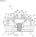
- FIGS. 12 and 13 are cross-sectional views schematically illustrating another example of the liquid introduction part 30 of the inspection chip 1 according to Embodiment 6.
- FIG. 12 is a cross-sectional view of the liquid introduction part 30.
- FIG. 13 is a cross-sectional view illustrating a state in which the protrusion part 66 is fitted in the liquid storage part 41.
- the same components as those in the example shown in FIG. 9 are indicated by the same reference numerals so as to omit the description thereof.
- the protrusion part 66 is provided as a separate body from the lid body part 61, and furthermore is capable of being detached from the lid body part 61.
- a through hole 634 is formed in the holding part 63 of the lid body part 61, into which the cylindrical part 662 of the protrusion part 66 is inserted.
- the lid body part 61 is not provided with the inner wall part 631 shown in FIG. 9 , which means that the lid body part 61 has a simpler configuration.
- the protrusion part 66 includes a sealing protrusion part 666 that is erected on the outer periphery of the body part 661.
- This sealing protruding part 666 is appressed to an inner surface 611 of the lid body part (base part) 61.
- the locking part 664 of the cylindrical part 662 is engaged with the upper edge part of the through hole 634 of the holding part 63. In this way, the protrusion part 66 is held by the lid body part 61.
- the lid body part 61 includes a positioning part 65 that is fitted in the opening part 411 of the liquid storage part 41. As shown in FIG. 12 , the positioning part 65 is protruded from the holding part 63 of the lid body part 61 toward the liquid reception part 40 (downward in FIG. 12 ) so as to be housed in the liquid storage part 41.
- an end part (lower end part) of the positioning part 65 goes into the liquid storage part 41 until it comes into contact with an engaging part 48 formed on the inner surface 414 as a step part and thus is stopped. As a result, the lid part 50 is appropriately positioned and attached to the liquid reception part 40.
- the inner surface 414 of the liquid storage part 41 includes the first inclined part 418, the step part 417 and the second inclined part 419, all of which are disposed under the positioning part 65.
- the first inclined part 418 on the upper side may be formed to have a funnel shape whose slope is gentler than the slope of the second inclined part 419.
- the liquid 70 is injected into and stored in the liquid reception part 40.
- the lid part 50 is attached to the liquid reception part 40 while the positioning part 65 is fitted in the liquid storage part 41.
- the bar-like member 80 is inserted into the pressing part 663 of the protrusion part 66 so as to press the protrusion part 66 downward.
- the protrusion part 66 can be moved with the locking part 664 being detached from the through hole 634 of the lid body part 61.
- the sealing protrusion part 666 of the protrusion part 66 slides on the inner surface 611 of the lid body part 61 while being appressed to the inner surface 611.
- the protrusion part 66 enters the liquid storage part 41.
- the liquid 70 is pushed out into the microchannel 21. Since the protrusion part 66 is elastic, when it is further pressed from the state shown in FIG. 13 , it can be deformed so that the body part 661 is appressed to the second inclined part 419 of the liquid storage part 41.
- the inspection chip 1 As described above, with the inspection chip 1 according to this Embodiment, it is also possible to easily introduce the liquid 70 into the microchannel 21 by attaching the lid part 50 to the liquid reception part 40 and pressing the protrusion part 66. In this way, it is possible to rapidly feed the liquid 70 to the microchannels 21, 22 and 23, which improves rapidity of analysis of the liquid 70.
- the protrusion part 66 is not particularly limited to a separate body from the lid body part 61.
- the protrusion part 66 and the lid body part 61 may be integrally formed via an elastic part or the like such that the protrusion part 61 is movable with respect to the lid part 61.
- the inspection chip 1 it is possible to seal the liquid reception part 40 by only a simple operation of attaching the lid part 50 to the liquid reception part 40, and at this time, the gas encapsulated in the liquid storage part 41 is pushed out by the protrusion part 52, which results in rapid introduction of the liquid 70 that is also pushed out from the liquid storage part 41 into the microchannel 21.
Landscapes
- Chemical & Material Sciences (AREA)
- Health & Medical Sciences (AREA)
- Analytical Chemistry (AREA)
- General Health & Medical Sciences (AREA)
- Hematology (AREA)
- Clinical Laboratory Science (AREA)
- Chemical Kinetics & Catalysis (AREA)
- Dispersion Chemistry (AREA)
- Sampling And Sample Adjustment (AREA)
Abstract
Description
- The present invention relates to an inspection chip and a liquid introduction method using the inspection chip.
- Recently, various tests such as a blood test and a genetic test as well as biochemical analysis have been performed using an inspection chip having microchannels to control supply and/or reactions of various kinds of specimens and samples. Especially in the fields such as the medical field and the biochemical field, there is a demand for downsizing and simplifying analytical equipment. Also, high-speed analysis and analyzing a trace specimen are required.
- In the conventional inspection chip, sampling equipment such as a micropipette or a syringe is generally used at the time of introduction of liquid such as a specimen into a microchannel. That is, dedicated sampling equipment is needed, which also requires complicated operations.
-
Patent Document 1 discloses, as one example, a microchip having a configuration in which a sample liquid introduction port communicated with a starting terminal of a liquid passageway is formed on the same plane as a gas supply port communicated with an ending terminal of a gas passageway, and a seal material is disposed to surround the sample liquid introduction port and the gas supply port. Thus, a vial can be directly connected to the sample liquid introduction port. - [Patent Document 1]
JP 5754190 - However, in the conventional inspection chip, a liquid feeding method using compressed air is adopted as a method for feeding the introduction liquid. Although there also is a passive feeding method using capillary action as the liquid feeding method, these methods take time to send the liquid. Furthermore, when the compressed air is used, it is also necessary to provide a dedicated compressed air generator.
- The present invention was made in consideration of the above circumstances, an object of which is to provide an inspection chip and a liquid introduction method in which liquid such as a specimen is simply and rapidly introduced into a microchannel without any dedicated compressed air generator to introduce the liquid.
- In order to achieve the above object, an inspection chip of the present invention includes: a body part including a microchannel; and a liquid introduction part introducing liquid into the microchannel. The liquid introduction part includes: a liquid reception part into which the liquid is injected; and a lid part capable of sealing the liquid reception part. The liquid reception part includes: a liquid storage part having an opening part in an upper part thereof; and a connection part connecting the liquid storage part and the microchannel. The lid part includes a protrusion part that protrudes so as to be fitted in the opening part and housed in the liquid storage part when the liquid reception part is sealed, and furthermore the protrusion part hermetically enters the liquid storage part. The lid part is attached to the liquid reception part, and then the liquid in the liquid storage part is pushed out into the microchannel through the connection part.
- With the specific configuration as described above, it is possible to easily seal the liquid reception part by attaching the lid part of the inspection chip to the liquid reception part. At this time, gas encapsulated in the liquid storage part is pushed out by the protrusion part, which pushes the liquid in the liquid storage part to the microchannel. Thus, it is possible to easily introduce the liquid into the microchannel.
- Also in the inspection chip having the above configuration, it is preferable that the liquid storage part has an inclined bottom part, and that the connection part connects the lowermost part of the bottom part and the microchannel.
- Also in the inspection chip having the above configuration, it is preferable that the protrusion part has a shape such that at least a part of the protrusion part comes into contact with an inner surface of the liquid storage part when the liquid reception part is sealed.
- Also in the inspection chip having the above configuration, the lid part may include: the protrusion part; and a base part holding the protrusion part. The protrusion part may be movable with respect to the base part.
- Also in the inspection chip having the above configuration, the protrusion part may be formed as a separate body from the base part, and may be detachable from the base part. In this case, it is preferable that the protrusion part includes a locking part capable of being engaged with the base part.
- Also in the inspection chip having the above configuration, the protrusion part may include a pressing part that is a recess toward the liquid storage part.
- Also in the inspection chip having the above configuration, the base part may include a positioning part that protrudes so as to be fitted in the opening part and housed in the liquid storage part.
- Also in the inspection chip having the above configuration, it is preferable that the protrusion part hermetically slides into the liquid storage part when the liquid reception part is sealed.
- Also in the inspection chip having the above configuration, the protrusion part may include a sealing protrusion part that protrudes outward from an outer surface of the protrusion part so as to be appressed to an inner surface of the liquid storage part.
- Also in the inspection chip having the above configuration, it is preferable that the protrusion part is elastically deformable.
- Also in the inspection chip having the above configuration, it is preferable that, in the liquid introduction part, the liquid storage part is provided on the body part so as to protrude from the body part. In this case, an outer surface of the liquid storage part may be provided with a part to be locked with which the lid part is engaged, and the lid part may be provided with a locking part that is engaged with the part to be locked.
- Also in the inspection chip having the above configuration, the liquid storage part and the lid part may respectively have thread structures to be threadably engaged with each other, and an external thread formed on either one of the liquid storage part and the lid part may be threadably engaged with an internal thread formed on the other one of the liquid storage part and the lid part.
- A liquid introduction method using the inspection chip having the above configuration is also within the technical range of the present invention. That is, in the liquid introduction method using an inspection chip including a liquid introduction part connected to a microchannel, the liquid introduction part includes: a liquid reception part into which liquid is injected; and a lid part capable of sealing the liquid reception part. The lid part has a protrusion part protrudingly provided. The liquid introduction method includes the steps of: injecting the liquid into the liquid reception part so that the liquid is stored; and attaching the lid part to the liquid reception part. In the attaching step, the lid part seals the liquid reception part, then, as the protrusion part enters the liquid reception part, gas in the liquid reception part pushes out the liquid into the microchannel, and thus the liquid is introduced into the microchannel.
- Also in the liquid introduction method having the above configuration, the protrusion part may be movable with respect to a base part of the lid part, and the protrusion part may enter the liquid reception part by being pressed.
- In the above-described configuration, it is possible to easily introduce the liquid in the liquid storage part into the microchannel by a simple operation of sealing the liquid reception part of the inspection chip using the lid part.
- With the present invention, the inspection chip can be provided, which has a simple configuration capable of rapidly introducing and sending liquid.
-
- [
FIG. 1 ]
FIG. 1 is a perspective view schematically illustrating an inspection chip according toEmbodiment 1 of the present invention. - [
FIG. 2 ]
FIG. 2 is a cross-sectional view schematically illustrating a liquid introduction part of the inspection chip. - [
FIGS. 3 ]
FIGS. 3(a) and 3(b) are diagrams for explaining a liquid introduction method using the inspection chip. - [
FIG. 4 ]
FIG. 4 is a cross-sectional view schematically illustrating the liquid introduction part of the inspection chip according to Embodiment 2 of the present invention. - [
FIG. 5 ]
FIG. 5 is a cross-sectional view schematically illustrating another example of the liquid introduction part of the inspection chip. - [
FIGS. 6 ]
FIGS. 6(a) and 6(b) are cross-sectional views schematically illustrating the liquid introduction part of the inspection chip according to Embodiment 3 of the present invention. - [
FIGS. 7 ]
FIGS. 7(a) and 7(b) are cross-sectional views schematically illustrating the liquid introduction part of the inspection chip according to Embodiment 4 of the present invention. - [
FIGS. 8 ]
FIGS. 8(a) and 8(b) are cross-sectional views schematically illustrating the liquid introduction part of the inspection chip according to Embodiment 5 of the present invention. - [
FIG. 9 ]
FIG. 9 is a cross-sectional view schematically illustrating the liquid introduction part of the inspection chip according to Embodiment 6 of the present invention. - [
FIG. 10 ]
FIG. 10 is a cross-sectional view illustrating a state in which a protrusion part provided on a lid part of the liquid introduction part is fitted in a liquid storage part. - [
FIG. 11 ]
FIG. 11 is a cross-sectional view illustrating a state in which the protrusion part is further fitted in the liquid storage part subsequent to the state inFIG. 10 . - [
FIG. 12 ]
FIG. 12 is a cross-sectional view schematically illustrating another example of the liquid introduction part of the inspection chip according to Embodiment 6. - [
FIG. 13 ]
FIG. 13 is a cross-sectional view illustrating a state in which the protrusion part provided on the lid part of the liquid introduction part is fitted in the liquid storage part. - An
inspection chip 1 and a liquid introduction method using theinspection chip 1 according to Embodiments of the present invention will be described with reference to the drawings. -
FIG. 1 is a perspective view schematically illustrating theinspection chip 1 according toEmbodiment 1.FIG. 2 is a cross-sectional view schematically illustrating aliquid introduction part 30 of theinspection chip 1.FIGS. 3(a) and 3(b) are diagrams for explaining the liquid introduction method using theinspection chip 1. - As shown in
FIG. 1 , theinspection chip 1 includes: abody part 20 having a general shape of a rectangular plate; and theliquid introduction part 30 to introduce liquid into amicrochannel 21 of thebody part 20. As shown inFIGS. 1 and2 , hereinafter a configuration is exemplarily described, in which theliquid introduction part 30 is provided on an upper surface of thebody part 20 of theinspection chip 1. Also, the orientation, the vertical direction and the like of theinspection chip 1 are described according to the state shown inFIG. 1 . However, it is only for the sake of understandability, and thus does not limit the direction and the like of theinspection chip 1 of the present invention when it is used. - The
body part 20 of theinspection chip 1 includes a plurality ofmicrochannels microchannel 21 is connected to theliquid introduction part 30. In the configuration exemplarily shown, a downstream end of themicrochannel 21 and a downstream end of themicrochannel 22 are both connected to areaction part 25 and joined so as to branch into a plurality ofmicrochannels 23. To each downstream end of themicrochannels 23, ananalysis part 26 is connected. - A
gas generation part 24 is provided upstream of themicrochannel 22. Thegas generation part 24 generates gas by external force such as light or heat. Thegas generation part 24 includes, for example, a light gas generating tape that generates gas at a predetermined timing so as to supply the generated gas to themicrochannel 22. Thus, trace reagent can be controlled to be supplied, and accordingly, no complicated liquid feeding mechanism is required. - As the liquid injected into the
liquid introduction part 30, micro droplets having a volume of, for example, 1 to 500 pl are used. The liquid injected into theliquid introduction part 30 is, for example, a specimen collected from a test subject. When the liquid is a specimen collected from the test subject, an operator is required to store the specimen in theinspection chip 1 every time the test is conducted. In this case also, the specimen can be simply and rapidly introduced into theinspection chip 1 so as to be supplied, not depending on proficiency of the operator. - The
microchannels respective microchannels FIG. 1 , themicrochannels - The
liquid introduction part 30 includes aliquid reception part 40 into which the liquid is injected and alid part 50 capable of sealing theliquid reception part 40. It is preferable that theliquid reception part 40 and thelid part 50 are connected to each other by a belt-shaped joiningpart 60. - As shown in
FIG. 2 , theliquid reception part 40 includes, in an integral manner: aliquid storage part 41 having an opened upper part and a bottom part; and aconnection part 42 that connects theliquid storage part 41 and themicrochannel 21. InFIG. 2 , the cross-section is shown in the state in which thelid part 50 is lifted upward from theliquid reception part 40 fixed to thebody part 20. Theliquid storage part 41 has anopening part 411 in the upper part, and an inclinedbottom part 412. Thebottom part 412 of theliquid storage part 41 has a tapered shape with a slope descending toward the substantial center part thereof. A connection opening 413 (seeFIG. 3(b) ) is opened in the lowermost part of thebottom part 412. - The
liquid storage part 41 has, for example, a cylindrical shapedinner surface 414, and thebottom part 412 preferably has a funnel shape. Anouter surface 415 of theliquid storage part 41 has also a cylindrical shape. Thebottom part 412 of theliquid storage part 41 has an inverted cone shape. - The
connection part 42 is connected to theconnection opening 413 in the lowermost part of thebottom part 412 so as to connect theliquid storage part 41 and themicrochannel 21. Theconnection part 42 is provided so as to protrude downward from theliquid storage part 41. Theconnection part 42 has aconnection channel 421 communicating with theconnection opening 413. Theconnection part 42 is fitted in and fixed to the upper surface of thebody part 20. Thus, theconnection channel 421 is connected to the upstream end of themicrochannel 21 of thebody part 20. - The shape of the
liquid storage part 41 is not limited to the above-described shape, provided that theliquid storage part 41 has a configuration in which thebottom part 412 is provided with theconnection opening 413 that is connected to theconnection part 42. For example, thebottom part 412 of theliquid storage part 41 is not particularly required to have an inverted cone shape to the extent that it has a slope. Theliquid storage part 41 may have a square-tube shapedinner surface 414 and thebottom part 412 may have an inverted pyramid shape. Also, theconnection opening 413 is not particularly required to be provided in the substantial center part of thebottom part 412. Theconnection opening 413 may be eccentrically provided with respect to the center part of thebottom part 412 to the extent that it is provided in the lowermost part. - The
microchannel 21 has aliquid inlet 211 that is opened to the outside of the system on an upstream side of the body part 20 (seeFIG. 3(b) ). Themicrochannel 21 extends in the thickness direction (vertical direction) of thebody part 20, and is bent to be extended in the liquid feeding direction X that orthogonally intersecting with the thickness direction. On the downstream side of themicrochannel 21, thereaction part 25 is provided, which holds, for example, the reagent. - The
lid part 50 of theliquid introduction part 30 includes, in an integral manner: abase part 51; aprotrusion part 52 that protrudes from one surface of thebase part 51; and an outerperipheral wall part 53 that is provided outside theprotrusion part 52. Thebase part 51 has a flat plate shape. Theprotrusion part 52 and the outerperipheral wall part 53 are provided so as to protrude in the same direction from thebase part 51. - The
protrusion part 52 has an outer surface smaller than an inner surface of theliquid storage part 41, and protrudes so as to be fitted in theliquid storage part 41 from theopening part 411 and thus is housed in theliquid storage part 41. In this case, anouter surface 521 of theprotrusion part 52 is formed to have a cylindrical shape whose outer diameter is, for example, smaller than the inner diameter of the cylindrical shapedliquid storage part 41. - Also, the
protrusion part 52 has a sealingprotrusion part 522 that protrudes outward from theouter surface 521. The sealingprotrusion part 522 is continuously formed on a protruding end part of theprotrusion part 52 in the circumferential direction of theouter surface 521, and has an annular shape or a flange shape. The sealingprotrusion part 522 is elastic, and is formed to have an outer diameter equal to or larger than the inner diameter of theliquid storage part 41. In this way, when theprotrusion part 52 is housed in theliquid storage part 41, the sealingprotrusion part 522 of theprotrusion part 52 is appressed to theinner surface 414 of theliquid storage part 41. - The protruding end part of the
protrusion part 52 faces thebottom part 412 of theliquid storage part 41 when it is housed in theliquid storage part 41. Theprotrusion part 52 has a taperedpart 523 that swells gradually from the protruding end part toward the substantial center part thereof so as to correspond to thebottom part 412 having a tapered shape with a slope descending toward the substantial center part thereof. - Also the
protrusion part 52 has a size that does not come into contact with thebottom part 412 of theliquid storage part 41 when theprotrusion part 52 is housed in theliquid storage part 41, while at least the sealingprotrusion part 522 is appressed to theinner surface 414 of theliquid storage part 41. Thus, when thelid part 50 is attached to theliquid reception part 40 and theprotrusion part 52 is housed in theliquid storage part 41, an airtight space is formed between theprotrusion part 52 and thebottom part 412. Since thetapered part 523 is provided, the airtight space can be smaller, which contributes to easiness of fitting theprotrusion part 52 in theliquid storage part 41. - Note that it does not matter whether the
protrusion part 52 comes into contact with thebottom part 412 of theliquid storage part 41 or not when theprotrusion part 52 is completely housed in theliquid storage part 41. - The outer
peripheral wall part 53 of thelid part 50 is formed to have a cylindrical shape surrounding outside theprotrusion part 52 at a predetermined interval from theouter surface 521 of theprotrusion part 52. Outside theprotrusion part 52, arecess part 54 having a cylindrical shape is formed, which is surrounded by theouter surface 521 of theprotrusion part 52, thebase part 51 and the outerperipheral wall part 53. The outerperipheral wall part 53 has a protruding length substantially the same as the height of theouter surface 415 of theliquid storage part 41. - Also, the
lid part 50 has aknob part 57 extending outward, which is provided on the outer surface of the outerperipheral wall part 53. In the configuration exemplarily shown, theknob part 57 protrudes from the part in the vicinity of the end of the outerperipheral wall part 53, which is opposite to thebase part 51. At the time of attaching thelid part 50 to theliquid reception part 40, an operator pinches theknob part 57 and covers theopening part 411 with thelid part 50 easily by bending and deforming the joiningpart 60. - It is preferable that the
liquid reception part 40 and thelid part 50 are each integrally made of a thermoplastic material such as: polypropylene (PP) resin; polyethylene (PE) resin; polystyrene (PS) resin; acrylonitrile butadiene styrene (ABS) resin; polymethyl methacrylate (PMMA) resin; polyvinyl alcohol (PVA) resin; polyvinylidene chloride (PVDC) resin; polyethylene terephthalate (PET) resin; polyamide (PA) resin; polyacetal (POM) resin; polycarbonate (PC) resin; polyvinylidene fluoride (PVDF) resin; polytetrafluoroethylene (PTFE) resin; cycloolefin polymer (COP) resin; or cycloolefin copolymer (COC) resin. More preferably, PP or PE is used as the resin material in the above materials. - The
liquid reception part 40 and thelid part 50 may be made of the same resin material or respectively made of different resin materials. It is preferable that at least one of theliquid reception part 40 and thelid part 50 is made of PP or PE. - With the above-described configuration, in the
liquid introduction part 30 of theinspection chip 1, theliquid storage part 41 is provided so as to protrude from thebody part 20. As shown inFIG. 1 , thelid part 50 coupled to theliquid reception part 40 is provided outside of thebody part 20. Theliquid introduction part 30 may be disposed at any position with respect to thebody part 20 of theinspection chip 1, which is not limited to the configuration exemplarily shown. Also, the general shape of theinspection chip 1 is not limited to the rectangular plate exemplarily shown. It may have any shape such as a disc shape or a fan shape. - In the
inspection chip 1 as shown inFIG. 2 , theliquid introduction part 30 is provided with theliquid reception part 40, the top part of which is opened. Theinspection chip 1 is adopted to detect biological information on virus and the like by introducing liquid (extraction liquid) 70 including a specimen collected, for example, from the nostril or the like of a human body. In this case, firstly, the liquid 70 is injected into theliquid reception part 40 of theliquid introduction part 30. The injectedliquid 70 is stored in thebottom part 412 of theliquid storage part 41 and theconnection channel 421. - Secondly, the
lid part 50 is attached to the liquid reception part 40 (attaching step). In the attaching step as shown inFIG. 3(a) , in the process where theliquid reception part 40 is covered with thelid part 50, theprotrusion part 52 provided in thelid part 50 enters theliquid storage part 41. The sealingprotrusion part 522 of theprotrusion part 52 of thelid part 50 hermetically slides on theinner surface 414 of theliquid storage part 41. Thus, theprotrusion part 52 is fitted in theliquid storage part 41. - In association with the sealing of the
liquid reception part 40 by thelid part 50, gas that exists in theliquid storage part 41 is encapsulated and pushed by theprotrusion part 52 so as to flow downward. The gas pushed by theprotrusion part 52 further pushes out the liquid 70 in theliquid storage part 41 toward themicrochannel 21 through theconnection channel 421 of theconnection part 42. - By pressing the
lid part 50 such that theprotrusion part 52 is further fitted in theliquid storage part 41, the liquid 70 is introduced into themicrochannel 21 as shown inFIG. 3(b) . When theliquid reception part 40 is sealed by thelid part 50, supply of the liquid is started. The liquid 70 introduced into themicrochannel 21 is fed from themicrochannel 21 to themicrochannel 23 on the downstream side via thereaction part 25. - Here, the capacity of the
liquid storage part 41 is a maximum amount ofliquid 70 capable of being fed. Therefore, it is possible to adjust the feeding amount of liquid depending on the capacity of theliquid storage part 41 provided in theinspection chip 1. - Also, when
lid part 50 is attached to theliquid reception part 40 so as to seal theliquid reception part 40, theprotrusion part 52 pushes out the liquid 70 via the gas encapsulated in theliquid storage part 41. Thus, the liquid 70 can be introduced into themicrochannel 21 without contacting with theprotrusion part 52. When thelid part 50 is pressed so that theknob part 57 comes into contact with theliquid reception part 40, theprotrusion part 52 is housed in theliquid storage part 41 and the outerperipheral wall part 53 covers theouter surface 415 of theliquid storage part 41. Since the sealingprotrusion part 522 of theprotrusion part 52 is appressed to theinner surface 414 of theliquid storage part 41, thelid part 50 is hardly detached once the sealing is completed. Thus, the sealed state is stably maintained. - As described above, with the
inspection chip 1 according to this Embodiment, it is possible to easily seal theliquid reception part 40 storing the liquid 70 by attaching thelid part 50 to theliquid reception part 40 at the time of introducing the liquid 70 into theinspection chip 1. Also, when theliquid reception part 40 is sealed, the gas encapsulated in theliquid storage part 41 is pushed out by theprotrusion part 52 of thelid part 50, which pushes the liquid 70 in theliquid storage part 41 to themicrochannel 21. Thus, it is possible to easily introduce the liquid 70. - In this way, it is possible to rapidly feed the liquid 70 to the
microchannels liquid reception part 40 into which the liquid 70 is injected by thelid part 50, which does not require any dedicated compressed air generator to feed the liquid 70. Thus, it is possible to form theinspection chip 1 with a simple configuration, which contributes reduction of production costs while reducing the size. -
FIGS. 4 and 5 are cross-sectional views schematically illustrating theliquid introduction part 30 of theinspection chip 1 according to Embodiment 2. In Embodiments 2 to 5 described below, the basic configuration of theinspection chip 1 is the same as that shown inEmbodiment 1, and respective structures of theliquid introduction part 30 are characteristic. Therefore, the characteristic structures of theliquid introduction part 30 are described in detail, and the other components are indicated by the same reference numerals asEmbodiment 1 so as to omit the description thereof. - In
Embodiment 1 described above, theinspection chip 1 has a configuration in which theprotrusion part 52 of thelid part 50 is provided with the sealingprotrusion part 522. However, the configuration of theinspection chip 1 is not limited thereto. It is sufficient for theprotrusion part 52 to have a configuration in which at least a part thereof comes into contact with the inner surface of theliquid storage part 41 when theliquid reception part 40 is sealed. Also, theprotrusion part 52 is not particularly required to have the above-described configuration to the extent that theprotrusion part 52 can hermetically slide into theliquid storage part 41 when theliquid reception part 40 is sealed. - For example, in the
inspection chip 1 shown inFIG. 4 , theprotrusion part 52 of thelid part 50 is not provided with the sealing protrusion part 522 (seeFIG. 2 ). Theouter surface 521 of theprotrusion part 52 is formed to have a straight cylindrical shape so as to be fitted in theliquid storage part 41. In this case, theouter surface 521 of theprotrusion part 52 is pressed so as to slide on theinner surface 414 of theliquid storage part 41, which pushes out the gas in theliquid storage part 41. By the pushed gas, the liquid 70 is pushed out into themicrochannel 21. - Also as shown in
FIGS. 4 and 5 , when thelid part 50 is capable of hermetically sealing theliquid reception part 40, the outerperipheral wall part 53 of thelid part 50 may be formed to have a protruding length smaller than the height of theouter surface 415 of theliquid storage part 41. In this configuration also, therecess part 54 formed between the outerperipheral wall part 53 and theprotrusion part 52 can position thelid part 50 when thelid part 50 is attached to theliquid reception part 40, thus therecess part 54 serves as a guide to fit theprotrusion part 52 in theliquid reception part 40, which improves workability. - Also as shown in
FIGS. 4 and 5 , theprotrusion part 52 is not particularly required to have the taperedpart 523 that swells gradually from the protruding end part toward the substantial center part thereof. With this configuration of theliquid introduction part 30, it is possible to form theinspection chip 1 having a simpler configuration while it is possible to rapidly introduce the liquid. - Also the
knob part 57 provided on thelid part 50 may be formed on the end part of the outerperipheral wall part 53 as shown inFIG. 2 or on the side of thebase part 51 as shown inFIG. 4 , provided that it protrudes from the outer surface of the outerperipheral wall part 53. -
FIGS. 6(a) and 6(b) are cross-sectional views schematically illustrating theliquid introduction part 30 of theinspection chip 1 according to Embodiment 3. - In
Embodiment 1, description was given on theliquid introduction part 30 having the configuration in which theliquid storage part 41 protrudes from thebody part 20. Theliquid introduction part 30 of theinspection chip 1 may also have a configuration in which theliquid reception part 40 and thelid part 50 are engaged with each other. - For example, as shown in
FIG. 6(a) , theouter surface 415 of theliquid storage part 41 has a part to be locked (a locked part) 416 with which thelid part 50 is to be engaged. On the other hand, thelid part 50 has a lockingpart 531 to be engaged with the lockedpart 416 of theliquid storage part 41. In this case, the lockedpart 416 is a groove-like recess part formed in the lower part of theouter surface 415 of theliquid storage part 41. In contrast, the lockingpart 531 is formed as a convex part protruding in the direction of theprotrusion part 52 from the end part of the outerperipheral wall part 53 of thelid part 50. - As shown in
FIG. 6(b) , when theliquid reception part 40 is sealed by thelid part 50, the lockedpart 416 of theliquid storage part 41 is engaged with the lockingpart 531 of thelid part 50, and accordingly, thelid part 50 is fixed to theliquid reception part 40. In this way, thelid part 50 is hardly detached, and the sealed state of theliquid reception part 40 is stably maintained. Also, at the time of sealing theliquid reception part 40 by thelid part 50, thelid part 50 can be pressed using, as a guide, engagement of the lockingpart 531 with the lockedpart 416. Thus, it is possible to reliably seal theliquid reception part 40. - Furthermore, as another configuration in which the
liquid reception part 40 and thelid part 50 are engaged with each other, theouter surface 415 of theliquid storage part 41 may have the lockedpart 416 as a convex part with which thelocking part 531 of thelid part 50 is elastically engaged. -
FIGS. 7(a) and 7(b) are cross-sectional views schematically illustrating theliquid introduction part 30 of theinspection chip 1 according to Embodiment 4. - In Embodiment 3, description was given on the configuration in which the
liquid storage part 41 protrudes from thebody part 20 and in which theliquid reception part 40 and thelid part 50 are engaged with each other so as to fix thelid part 50 to theliquid reception part 40. However, the configuration in which thelid part 50 is fixed to theliquid reception part 40 is not limited thereto. Both thelid part 50 and theliquid reception part 40 may have thread parts to be threadably engaged with each other. - For example, as shown in
FIG. 7(a) , theouter surface 415 of the cylindrical shapedliquid storage part 41 has anexternal thread 43 while the cylindrical shaped outerperipheral wall part 53 of thelid part 50 has, on the inner surface thereof, aninternal thread 55 to be threadably engaged with theexternal thread 43 of theliquid storage part 41. In this case, thelid part 50 is rotated such that theinternal thread 55 is screwed and threadably engaged with theexternal thread 43, and thus theliquid reception part 40 is sealed by thelid part 50. - As shown in
FIG. 7(b) , when theliquid reception part 40 is sealed by thelid part 50, theinternal thread 55 of the outerperipheral wall part 53 is threadably engaged with theexternal thread 43 of theliquid storage part 41, and thelid part 50 is fixed to theliquid reception part 40. In this way, thelid part 50 is hardly detached, and the sealed state of theliquid reception part 40 is stably maintained. In this case where the thread structures are provided to make thread engagement, theliquid reception part 40 and thelid part 50 are each formed as a separate body, and no joiningpart 60 is needed between theliquid reception part 40 and thelid part 50. Alternatively, theliquid reception part 40 and thelid part 50 may be coupled by the joiningpart 60 having a loop such that thelid part 50 is rotatable. -
FIGS. 8(a) and 8(b) are cross-sectional views schematically illustrating theliquid introduction part 30 of theinspection chip 1 according to Embodiment 5. - In Embodiment 4, description was given on the configuration in which the
external thread 43 is provided on theliquid reception part 40 while theinternal thread 55 is provided on thelid part 50, as the configuration in which thelid part 50 is fixed to theliquid reception part 40. However, theinspection chip 1 of the present invention is not limited to the above configuration. Aninternal thread 44 may be provided on theliquid reception part 40 and anexternal thread 56 may be provided on thelid part 50 to the extent that they are formed as the thread structures to be threadably engaged with each other. - For example, as shown in
FIG. 8(a) , theinner surface 414 of the cylindrical shapedliquid storage part 41 may have theinternal thread 44 while theouter surface 521 of theprotrusion part 52 of thelid part 50 may have theexternal thread 56. In this case also, thelid part 50 is rotated such that theexternal thread 56 is screwed and threadably engaged with theinternal thread 44, thus theliquid reception part 40 can be sealed by thelid part 50. - As shown in
FIG. 8(b) , when theliquid reception part 40 is sealed by thelid part 50, theexternal thread 56 of theprotrusion part 52 is threadably engaged with theinternal thread 44 of theliquid storage part 41, and thelid part 50 is fixed to theliquid reception part 40. In this way, thelid part 50 is hardly detached, and the sealed state of theliquid reception part 40 is stably maintained. - The
lid part 50 may have the configuration including the outerperipheral wall part 53 similarly to the above Embodiments, or the configuration not including the outerperipheral wall part 53 as shown inFIGS. 8 . Also, when thelid part 50 is completely screwed, thetapered part 523 of theprotrusion part 52 may reach thebottom part 412 of theliquid storage part 41. -
FIG. 9 is a cross-sectional view schematically illustrating theliquid introduction part 30 of theinspection chip 1 according to Embodiment 6.FIGS. 10 and11 are cross-sectional views sequentially illustrating the state in which aprotrusion part 66 provided on thelid part 50 is fitted in aliquid storage part 41. Each cross-section in these Figures illustrates the state in which theliquid reception part 40 is sealed by thelid part 50. - In the
inspection chip 1 of the present invention, thelid part 50 of theliquid introduction part 30 is not limited to the configuration having, in an integral manner, thebase part 51 and theprotrusion part 52 that protrudes from one surface of thebase part 51. The base part and the protrusion part may be provided each as a separate body. - That is, in the
inspection chip 1 according to this Embodiment as exemplarily shown inFIG. 9 , thelid part 50 to seal theliquid reception part 40 is provided with alid body part 61 as the base part and theprotrusion part 66, both are separated from each other. Theprotrusion part 66 is held by thelid body part 61. - The lid body part (base part) 61 includes: a
cover part 62 that covers the upper part of theliquid reception part 40; and a holdingpart 63 that holds theprotrusion part 66 provided as a separate body. Thecover part 62 and the holdingpart 63 are integrally formed. Thecover part 62 includes: a disc-shaped upper surface part 621 that covers the upper surface of theliquid reception part 40 so as to come into contact with the upper surface; and arib part 622 that protrudes from the upper surface part 621 toward the liquid reception part 40 (i.e. downward inFIG. 9 ). Aknob part 64 is protrudingly provided on therib part 622 so as to extend outward. - The holding
part 63 is disposed at a substantial center part of thelid body part 61 so as to expand upward from the upper surface part 621. The holdingpart 63 includes: a substantially cylindrical shapedinner wall part 631; alocking recess part 632 formed in an upper edge part of theinner wall part 631; and afitting recess part 633 in which theprotrusion part 66 is fitted. Theinner wall part 631 is provided on the substantial center part of thelid body part 61. A through hole is formed inside theinner wall part 631 so as to penetrate inside and outside thelid body part 61. Aprotrusion part 66 is engaged with thelocking recess part 632. Thefitting recess part 633 is provided around the outer periphery of theinner wall part 631, and has a concave shape with the opening toward the liquid reception part 40 (i.e. downward inFIG. 9 ). - In the holding
part 63, respective parts of theprotrusion part 66 are disposed in the inside of theinner wall part 631 and in thefitting recess part 633, while a lockingpart 664 of theprotrusion part 66 is engaged with thelocking recess part 632. In this way, theprotrusion part 66 is held by the holdingpart 63 of thelid body part 61. - The
protrusion part 66 includes, in an integral manner: abody part 661; acylindrical part 662 extending upward from thebody part 661; and afitting protrusion part 665 provided outside thecylindrical part 662. Thebody part 661 to cover theliquid reception part 40 is formed to have a size that can close theopening part 411 of theliquid storage part 41. The bottom surface of the body part 661 (i.e. the surface facing the liquid storage part 41) has a downward convex shape having a gentle curve. - The
cylindrical part 662 of theprotrusion part 66 is fitted in the inside of theinner wall part 631 of the holdingpart 63. The lockingpart 664 is formed on the end part of thecylindrical part 662 so as to extend outward. The lockingpart 664 is engaged with thelocking recess part 632 of the holdingpart 63. The inside of thecylindrical part 662 is recessed toward theliquid storage part 41 and has a bottom part, which forms apressing part 663. Thefitting protrusion part 665 extends upward from the outer edge part of thebody part 661 so as to be fitted in thefitting recess part 633. Theprotrusion part 66 is formed as a protrusion part so that thebody part 661 is housed in theliquid storage part 41. - The
lid body part 61 and theliquid reception part 40 are connected by the joiningpart 60 so as to be opened and closed. On thelid body part 61, aknob part 64 is protrudingly provided on the opposite side of the joiningpart 60. At the time of attaching thelid part 50 to theliquid reception part 40, an operator pinches theknob part 64 and covers theliquid reception part 40 with thecover part 62 so as to engage the respective components with each other. - On the other hand, in the
liquid reception part 40, theliquid storage part 41 includes, in an integral manner: theconnection part 42; a firstfixed part 45; a secondfixed part 46; and acontact part 47. Theliquid reception part 40 is provided so as to protrude upward from thebody part 20 of theinspection chip 1. As shown inFIG. 9 , the firstfixed part 45 protruding downward from theconnection part 42 and the secondfixed part 46 provided outside theliquid storage part 41 are respectively engaged with recess parts formed in the upper surface of thebody part 20. Thus, theliquid reception part 40 is fixed to thebody part 20. - The
contact part 47 of theliquid reception part 40 is a part to be covered with the upper surface part 621 of thecover part 62 of thelid body part 61. Thecontact part 47 has a concave/convex shape corresponding to the inner surface shape of the upper surface part 621, so that thecontact part 47 and the upper surface part 621 are positioned to each other. The secondfixed part 46 extends downward from the outer peripheral part of thecontact part 47 to thebody part 20. A projection may be formed at the lower end part of the secondfixed part 46 so as to be engaged with thebody part 20. - The
liquid storage part 41 has theopening part 411 in the upper part thereof. Theinner surface 414 has a tapered shape with a slope descending toward theconnection part 42. On the periphery of theopening part 411, thecontact part 47 is provided so as to extend outward. In the configuration exemplarily shown, theinner surface 414 of theliquid storage part 41 contains a firstinclined part 418 on the upper side, and a secondinclined part 419 on the lower side, with respect to astep part 417. The firstinclined part 418 has a slope similar to the substantially cylindrical shape while the secondinclined part 419 has a further gentle slope compared to the firstinclined part 418 and thus has a funnel shape. Theconnection part 42 is provided in the lowermost part of the secondinclined part 419 so as to connect theliquid storage part 41 and themicrochannel 21. Theconnection part 42 has anopening 422 that is connected to the upstream end of themicrochannel 21. - As described above, the
liquid reception part 40 is protrudingly provided on thebody part 20 with theliquid storage part 41 being the center part thereof. A hollow part is formed between the outer surface of theliquid storage part 41 and the secondfixed part 46. - It is preferable that the
liquid reception part 40 and thelid body part 61 are each integrally made of a thermoplastic material such as: polypropylene (PP) resin; polyethylene (PE) resin; polystyrene (PS) resin; or acrylonitrile butadiene styrene (ABS) resin. Theliquid reception part 40 and thelid body part 61 may be made of the same resin material or respectively made of different resin materials. - In contrast to the above, it is preferable that the
protrusion part 66 of thelid part 50 is made of an elastically deformable resin material such as polyolefin resin or elastomer. Examples of the resin materials suitable for forming theprotrusion part 66 include: polypropylene (PP) resin; polyethylene (PE) resin; styrene-based elastomer; olefin based elastomer; polyester-based elastomer; and polyurethane-based elastomer. - Since the
protrusion part 66 is provided as a separate body from thelid body part 61, theprotrusion part 66 is movable to protrude from thelid body part 61, and furthermore is capable of being detached from thelid body part 61. - As shown in
FIG. 9 , thebody part 661 of theprotrusion part 66 is formed to have an outer diameter substantially corresponding to or slightly larger than the inner diameter of theopening part 411 of theliquid storage part 41. Also, thefitting protrusion part 665 of theprotrusion part 66 is formed to have an outer diameter larger than the inner diameter of theopening part 411. Thefitting protrusion part 665 is elastically deformed and bent with respect to thebody part 661 so as to be fitted in thefitting recess part 633. - Unlike
Embodiment 1 and the like as described above, in this Embodiment, theprotrusion part 66 is held by thelid body part 61, and a part of thebody part 661 is provided to protrude downward from the upper surface part 621 of thelid body part 61. In this state, theprotrusion part 66 is movable downward, accordingly it can be fitted in theliquid storage part 41 through theopening part 411. Since theprotrusion part 52 is elastic, it can be deformed when it is fitted in theliquid storage part 41. Thus, it is appressed to theinner surface 414 of theliquid storage part 41 so as to be hermetically fitted therein. - As shown in
FIGS. 10 and11 , when theprotrusion part 52 is housed in theliquid storage part 41, its general shape is deformed by coming into contact with the firstinclined part 418 and the secondinclined part 419 of theliquid storage part 41 so as to be appressed to theinner surface 414 of theliquid storage part 41. When thelid part 50 is attached to theliquid reception part 40 and theprotrusion part 66 is housed in theliquid storage part 41, an airtight space is formed in theliquid storage part 41. As theprotrusion part 66 further enters theliquid storage part 41, the airtight space becomes smaller. Thus, the liquid 70 can be pushed out into themicrochannel 21. Note that it does not matter whether theprotrusion part 66 comes into contact with the lowermost part of theliquid storage part 41 or not when theprotrusion part 66 is completely housed in theliquid storage part 41. - In the liquid introduction method using the
inspection chip 1 according to this Embodiment, the liquid 70 is injected into and stored in theliquid storage part 41 of theliquid reception part 40. Then, thelid part 50 is attached to theliquid reception part 40 by pinching and moving theknob part 64 of the lid part 50 (attaching step). As shown inFIG. 9 , thelid part 50 is attached to theliquid reception part 40 by fitting therib part 622 of thelid body part 61 in the top part of the secondfixed part 46 of theliquid reception part 40 while covering thecontact part 47 with thecover part 62. Theprotrusion part 66 is held by the holdingpart 63 of thelid body part 61, and the lockingpart 664 of theprotrusion part 66 is engaged with thelocking recess part 632 of thelid body part 61. Theopening part 411 of theliquid storage part 41 is closed by theprotrusion part 66. - Then, as shown in
FIG. 10 , a bar-like member 80 is inserted into thepressing part 663 of theprotrusion part 66 so as to press theprotrusion part 66 downward. Thus, the lockingpart 664 of theprotrusion part 66 is disengaged from the lockingrecess part 632 of thelid body part 61 while thefitting protrusion part 665 is detached from thefitting recess part 633. Thecylindrical part 662 slides on the inner surface of theinner wall part 631 of thelid body part 61 so as to move downward. Thebody part 661 enters theliquid storage part 41. - As the
protrusion part 66 is detached from thelid body part 61 and enters theliquid storage part 41, the gas in theliquid storage part 41 is pressed downward. Thefitting protrusion part 665 of theprotrusion part 66 is deformed such that the outer surface thereof is appressed to the firstinclined part 418 of theliquid storage part 41, and thus enters theliquid storage part 41. The liquid 70 in theliquid storage part 41 is pushed out into themicrochannel 21 through theconnection opening 422. - By continuously pressing the
pressing part 663, theprotrusion part 66 is further deformed and fitted in theliquid storage part 41, as shown inFIG. 11 . For example, thebody part 661 of theprotrusion part 66 can also be deformed to be appressed to the secondinclined part 419 of theliquid storage part 41. The liquid 70 introduced into themicrochannel 21 is supplied, from themicrochannel 21, to themicrochannel 23 on the downstream side via the reaction part 25 (seeFIG. 1 ). -
FIGS. 12 and13 are cross-sectional views schematically illustrating another example of theliquid introduction part 30 of theinspection chip 1 according to Embodiment 6.FIG. 12 is a cross-sectional view of theliquid introduction part 30.FIG. 13 is a cross-sectional view illustrating a state in which theprotrusion part 66 is fitted in theliquid storage part 41. InFIGS. 12 and13 , the same components as those in the example shown inFIG. 9 are indicated by the same reference numerals so as to omit the description thereof. - In the example shown in
FIG. 12 also, theprotrusion part 66 is provided as a separate body from thelid body part 61, and furthermore is capable of being detached from thelid body part 61. A throughhole 634 is formed in the holdingpart 63 of thelid body part 61, into which thecylindrical part 662 of theprotrusion part 66 is inserted. Also, thelid body part 61 is not provided with theinner wall part 631 shown inFIG. 9 , which means that thelid body part 61 has a simpler configuration. In this case, theprotrusion part 66 includes a sealingprotrusion part 666 that is erected on the outer periphery of thebody part 661. Thissealing protruding part 666 is appressed to aninner surface 611 of the lid body part (base part) 61. The lockingpart 664 of thecylindrical part 662 is engaged with the upper edge part of the throughhole 634 of the holdingpart 63. In this way, theprotrusion part 66 is held by thelid body part 61. - Furthermore, the
lid body part 61 includes apositioning part 65 that is fitted in theopening part 411 of theliquid storage part 41. As shown inFIG. 12 , thepositioning part 65 is protruded from the holdingpart 63 of thelid body part 61 toward the liquid reception part 40 (downward inFIG. 12 ) so as to be housed in theliquid storage part 41. When thelid part 50 is attached to theliquid reception part 40, an end part (lower end part) of thepositioning part 65 goes into theliquid storage part 41 until it comes into contact with anengaging part 48 formed on theinner surface 414 as a step part and thus is stopped. As a result, thelid part 50 is appropriately positioned and attached to theliquid reception part 40. - Also, the
inner surface 414 of theliquid storage part 41 includes the firstinclined part 418, thestep part 417 and the secondinclined part 419, all of which are disposed under thepositioning part 65. As shown inFIG. 12 , the firstinclined part 418 on the upper side may be formed to have a funnel shape whose slope is gentler than the slope of the secondinclined part 419. - In the liquid introduction method in this case, the liquid 70 is injected into and stored in the
liquid reception part 40. Then, thelid part 50 is attached to theliquid reception part 40 while thepositioning part 65 is fitted in theliquid storage part 41. Successively, as shown inFIG. 13 , the bar-like member 80 is inserted into thepressing part 663 of theprotrusion part 66 so as to press theprotrusion part 66 downward. Thus, theprotrusion part 66 can be moved with the lockingpart 664 being detached from the throughhole 634 of thelid body part 61. The sealingprotrusion part 666 of theprotrusion part 66 slides on theinner surface 611 of thelid body part 61 while being appressed to theinner surface 611. Thus, theprotrusion part 66 enters theliquid storage part 41. The liquid 70 is pushed out into themicrochannel 21. Since theprotrusion part 66 is elastic, when it is further pressed from the state shown inFIG. 13 , it can be deformed so that thebody part 661 is appressed to the secondinclined part 419 of theliquid storage part 41. - As described above, with the
inspection chip 1 according to this Embodiment, it is also possible to easily introduce the liquid 70 into themicrochannel 21 by attaching thelid part 50 to theliquid reception part 40 and pressing theprotrusion part 66. In this way, it is possible to rapidly feed the liquid 70 to themicrochannels protrusion part 66 is not particularly limited to a separate body from thelid body part 61. For example, theprotrusion part 66 and thelid body part 61 may be integrally formed via an elastic part or the like such that theprotrusion part 61 is movable with respect to thelid part 61. - In the
inspection chip 1 according to any ofEmbodiments 1 to 6, it is possible to seal theliquid reception part 40 by only a simple operation of attaching thelid part 50 to theliquid reception part 40, and at this time, the gas encapsulated in theliquid storage part 41 is pushed out by theprotrusion part 52, which results in rapid introduction of the liquid 70 that is also pushed out from theliquid storage part 41 into themicrochannel 21. - The present invention may be embodied in other forms without departing from the gist or essential characteristics thereof. The foregoing embodiments are therefore to be considered in all respects as illustrative and not limiting. The scope of the invention is indicated by the appended claims rather than by the foregoing description, and all modifications and changes that come within the meaning and range of equivalency of the claims are intended to be embraced therein. This application claims priority based on
Japanese Patent Application No. 2020-107246 -
- 1
- Inspection chip
- 20
- Body part
- 21, 22, 23
- Microchannel
- 211
- Liquid inlet
- 24
- Gas generation part
- 25
- Reaction part
- 26
- Analysis part
- 30
- Liquid introduction part
- 40
- Liquid reception part
- 41
- Liquid storage part
- 411
- Opening part
- 412
- Bottom part
- 413
- Connection opening
- 414
- Inner surface
- 415
- Outer surface
- 416
- Locked part
- 418
- First inclined part
- 419
- Second inclined part
- 42
- Connection part
- 421
- Connection channel
- 422
- Connection opening
- 43
- External thread
- 44
- Internal thread
- 50
- Lid part
- 51
- Base part
- 52
- Protrusion part
- 521
- Outer surface
- 522
- Sealing protrusion part
- 523
- Tapered part
- 53
- Outer peripheral wall part
- 531
- Locking part
- 54
- Recess part
- 55
- Internal thread
- 56
- External thread
- 60
- Joining part
- 61
- Lid body part (base part)
- 62
- Cover part
- 63
- Holding part
- 65
- Positioning part
- 66
- Protrusion part
- 661
- Body part
- 662
- Cylindrical part
- 663
- Pressing part
- 664
- Locking part
- 665
- Fitting protrusion part
- 666
- Sealing protrusion part
- 70
- Liquid
Claims (16)
- An inspection chip comprising: a body part including a microchannel; and a liquid introduction part introducing liquid into the microchannel, whereinthe liquid introduction part includes: a liquid reception part into which the liquid is injected; and a lid part capable of sealing the liquid reception part,the liquid reception part includes: a liquid storage part having an opening part in an upper part thereof; and a connection part connecting the liquid storage part and the microchannel,the lid part includes a protrusion part that protrudes so as to be fitted in the opening part and be housed in the liquid storage part when the liquid reception part is sealed, and furthermore the protrusion part hermetically enters the liquid storage part, andthe lid part is attached to the liquid reception part, and then the liquid in the liquid storage part is pushed out into the microchannel through the connection part.
- The inspection chip according to claim 1, whereinthe liquid storage part has an inclined bottom part, andthe connection part connects a lowermost part of the bottom part and the microchannel.
- The inspection chip according to claim 1 or 2, wherein
the protrusion part has a shape such that at least a part of the protrusion part comes into contact with an inner surface of the liquid storage part when the liquid reception part is sealed. - The inspection chip according to any one of claims 1 to 3, whereinthe lid part includes: the protrusion part; and a base part holding the protrusion part, andthe protrusion part is movable with respect to the base part.
- The inspection chip according to claim 4, wherein
the protrusion part is formed as a separate body from the base part, and is detachable from the base part. - The inspection chip according to claim 5, wherein
the protrusion part includes a locking part capable of being engaged with the base part. - The inspection chip according to any one of claims 4 to 6, wherein
the protrusion part includes a pressing part that is a recess toward the liquid storage part. - The inspection chip according to any one of claims 4 to 7, wherein
the base part includes a positioning part that protrudes so as to be fitted in the opening part and be housed in the liquid storage part. - The inspection chip according to any one of claims 1 to 8, wherein
the protrusion part hermetically slides into the liquid storage part when the liquid reception part is sealed. - The inspection chip according to any one of claims 1 to 9, wherein
the protrusion part includes a sealing protrusion part that protrudes outward from an outer surface of the protrusion part so as to be appressed to an inner surface of the liquid storage part. - The inspection chip according to any one of claims 1 to 10, wherein
the protrusion part is elastically deformable. - The inspection chip according to any one of claims 1 to 11, wherein
in the liquid introduction part, the liquid storage part is provided on the body part so as to protrude from the body part. - The inspection chip according to claim 12, whereinan outer surface of the liquid storage part is provided with a part to be locked with which the lid part is engaged, andthe lid part is provided with a locking part that is engaged with the part to be locked.
- The inspection chip according to claim 3, whereinthe liquid storage part and the lid part respectively have thread structures to be threadably engaged with each other, andan external thread formed on either one of the liquid storage part and the lid part is threadably engaged with an internal thread formed on a remaining one of the liquid storage part and the lid part.
- A liquid introduction method using an inspection chip including a liquid introduction part connected to a microchannel, the liquid introduction part including: a liquid reception part into which liquid is injected; and a lid part capable of sealing the liquid reception part, the lid part having a protrusion part protrudingly provided,
the liquid introduction method comprising the steps of:injecting the liquid into the liquid reception part so that the liquid is stored; andattaching the lid part to the liquid reception part, whereinin the attaching step, the lid part seals the liquid reception part, then, as the protrusion part enters the liquid reception part, gas in the liquid reception part pushes out the liquid into the microchannel, and thus the liquid is introduced into the microchannel. - The liquid introduction method according to claim 15, whereinthe protrusion part is movable with respect to a base part of the lid part, andthe protrusion part enters the liquid reception part by being pressed.
Applications Claiming Priority (2)
| Application Number | Priority Date | Filing Date | Title |
|---|---|---|---|
| JP2020107246 | 2020-06-22 | ||
| PCT/JP2021/023204 WO2021261399A1 (en) | 2020-06-22 | 2021-06-18 | Inspection chip and liquid introduction method |
Publications (2)
| Publication Number | Publication Date |
|---|---|
| EP4170354A1 true EP4170354A1 (en) | 2023-04-26 |
| EP4170354A4 EP4170354A4 (en) | 2024-01-17 |
Family
ID=79281321
Family Applications (1)
| Application Number | Title | Priority Date | Filing Date |
|---|---|---|---|
| EP21829597.0A Pending EP4170354A4 (en) | 2020-06-22 | 2021-06-18 | Inspection chip and liquid introduction method |
Country Status (5)
| Country | Link |
|---|---|
| US (1) | US20230061763A1 (en) |
| EP (1) | EP4170354A4 (en) |
| JP (1) | JPWO2021261399A1 (en) |
| CN (1) | CN115485567A (en) |
| WO (1) | WO2021261399A1 (en) |
Family Cites Families (9)
| Publication number | Priority date | Publication date | Assignee | Title |
|---|---|---|---|---|
| US5735825A (en) * | 1996-03-22 | 1998-04-07 | Merit Medical Systems, Inc. | Syringe plunger tip |
| WO2009113487A1 (en) * | 2008-03-13 | 2009-09-17 | コニカミノルタエムジー株式会社 | Micro inspection chip and method of dividing liquid for micro inspection chip |
| JP5754190B2 (en) | 2011-03-18 | 2015-07-29 | ソニー株式会社 | Microchip, sample liquid supply apparatus, sample liquid supply method, and analysis apparatus |
| JP6032837B2 (en) * | 2012-08-24 | 2016-11-30 | 株式会社システムロード | Analysis equipment |
| JP5931709B2 (en) * | 2012-12-12 | 2016-06-08 | 株式会社ティー・ティー・エム | Body fluid component testing equipment |
| JP6937686B2 (en) * | 2015-04-30 | 2021-09-22 | シスメックス株式会社 | Liquid-sealed cartridge, sample analyzer, and sample analysis method |
| US10242437B2 (en) * | 2016-01-15 | 2019-03-26 | W. L. Gore & Associates, Inc. | Systems and methods for detecting syringe seal defects |
| JP7014592B2 (en) * | 2017-12-26 | 2022-02-01 | 積水化学工業株式会社 | Weighing structure and microchip |
| JP2020107246A (en) | 2018-12-28 | 2020-07-09 | 株式会社オービック | Component management apparatus, component management method, and component management program |
-
2021
- 2021-06-18 JP JP2022531940A patent/JPWO2021261399A1/ja active Pending
- 2021-06-18 WO PCT/JP2021/023204 patent/WO2021261399A1/en unknown
- 2021-06-18 EP EP21829597.0A patent/EP4170354A4/en active Pending
- 2021-06-18 CN CN202180025716.5A patent/CN115485567A/en active Pending
- 2021-06-18 US US17/800,344 patent/US20230061763A1/en active Pending
Also Published As
| Publication number | Publication date |
|---|---|
| US20230061763A1 (en) | 2023-03-02 |
| WO2021261399A1 (en) | 2021-12-30 |
| CN115485567A (en) | 2022-12-16 |
| JPWO2021261399A1 (en) | 2021-12-30 |
| EP4170354A4 (en) | 2024-01-17 |
Similar Documents
| Publication | Publication Date | Title |
|---|---|---|
| CA2694787C (en) | Apparatus for delivering pipettable substances | |
| KR100985426B1 (en) | System for automatic opening of reagent vessels | |
| CN108027202B (en) | Dry chemical container | |
| KR101805023B1 (en) | Device for preparing and dispensing biological sample | |
| EP4364850A1 (en) | Microfluidic chip | |
| WO2022121394A1 (en) | Multi-channel microfluidic sample adding device, assembly, and use thereof | |
| EP3290928A1 (en) | Liquid encapsulation cartridge, sample analysis device, and sample analysis method | |
| WO2023087821A1 (en) | Reagent pre-embedding and sample injecting device, and sample injection method therefor and application thereof | |
| EP4170354A1 (en) | Inspection chip and liquid introduction method | |
| US11964272B2 (en) | Detection chip, preparation method and use method thereof, and detection device | |
| CN106289933B (en) | Cover body and device for storing and mixing solid and liquid | |
| JP7014592B2 (en) | Weighing structure and microchip | |
| CN113101986B (en) | Device for storing and releasing reagent and microfluidic device | |
| EP4039359A1 (en) | Microchannel chip | |
| EP3467467A1 (en) | Liquid injection attachment | |
| CN112141483A (en) | Container and method of using same | |
| US20230111413A1 (en) | Sample pretreatment tube | |
| US20220288580A1 (en) | Liquid transfer device | |
| EP3508857A1 (en) | Attachment for liquid injection | |
| US20190255524A1 (en) | Transfer arrays for simultaneously transferring multiple aliquots of fluid | |
| EP3462158A1 (en) | Liquid injection attachment, and liquid injecting device | |
| CN113275045A (en) | Detection chip, operation method thereof and detection system | |
| CN208852905U (en) | A kind of liquid storage and automatic sampling apparatus | |
| US20220055028A1 (en) | Fluid handling system | |
| CN113101985A (en) | Detection chip and detection system |
Legal Events
| Date | Code | Title | Description |
|---|---|---|---|
| STAA | Information on the status of an ep patent application or granted ep patent |
Free format text: STATUS: THE INTERNATIONAL PUBLICATION HAS BEEN MADE |
|
| PUAI | Public reference made under article 153(3) epc to a published international application that has entered the european phase |
Free format text: ORIGINAL CODE: 0009012 |
|
| STAA | Information on the status of an ep patent application or granted ep patent |
Free format text: STATUS: REQUEST FOR EXAMINATION WAS MADE |
|
| 17P | Request for examination filed |
Effective date: 20220912 |
|
| AK | Designated contracting states |
Kind code of ref document: A1 Designated state(s): AL AT BE BG CH CY CZ DE DK EE ES FI FR GB GR HR HU IE IS IT LI LT LU LV MC MK MT NL NO PL PT RO RS SE SI SK SM TR |
|
| DAV | Request for validation of the european patent (deleted) | ||
| DAX | Request for extension of the european patent (deleted) | ||
| REG | Reference to a national code |
Ref country code: DE Ref legal event code: R079 Free format text: PREVIOUS MAIN CLASS: G01N0037000000 Ipc: B01L0003000000 |
|
| A4 | Supplementary search report drawn up and despatched |
Effective date: 20231214 |
|
| RIC1 | Information provided on ipc code assigned before grant |
Ipc: B01L 3/00 20060101AFI20231208BHEP |