EP4170214B1 - Tragstruktur für kabel und/oder rohre und verfahren zu deren herstellung - Google Patents
Tragstruktur für kabel und/oder rohre und verfahren zu deren herstellung Download PDFInfo
- Publication number
- EP4170214B1 EP4170214B1 EP22197760.6A EP22197760A EP4170214B1 EP 4170214 B1 EP4170214 B1 EP 4170214B1 EP 22197760 A EP22197760 A EP 22197760A EP 4170214 B1 EP4170214 B1 EP 4170214B1
- Authority
- EP
- European Patent Office
- Prior art keywords
- profile
- wall
- crosstie
- profiles
- crossties
- Prior art date
- Legal status (The legal status is an assumption and is not a legal conclusion. Google has not performed a legal analysis and makes no representation as to the accuracy of the status listed.)
- Active
Links
Images

Classifications
-
- F—MECHANICAL ENGINEERING; LIGHTING; HEATING; WEAPONS; BLASTING
- F16—ENGINEERING ELEMENTS AND UNITS; GENERAL MEASURES FOR PRODUCING AND MAINTAINING EFFECTIVE FUNCTIONING OF MACHINES OR INSTALLATIONS; THERMAL INSULATION IN GENERAL
- F16L—PIPES; JOINTS OR FITTINGS FOR PIPES; SUPPORTS FOR PIPES, CABLES OR PROTECTIVE TUBING; MEANS FOR THERMAL INSULATION IN GENERAL
- F16L3/00—Supports for pipes, cables or protective tubing, e.g. hangers, holders, clamps, cleats, clips, brackets
- F16L3/26—Supports for pipes, cables or protective tubing, e.g. hangers, holders, clamps, cleats, clips, brackets specially adapted for supporting the pipes all along their length, e.g. pipe channels or ducts
-
- H—ELECTRICITY
- H02—GENERATION; CONVERSION OR DISTRIBUTION OF ELECTRIC POWER
- H02G—INSTALLATION OF ELECTRIC CABLES OR LINES, OR OF COMBINED OPTICAL AND ELECTRIC CABLES OR LINES
- H02G3/00—Installations of electric cables or lines or protective tubing therefor in or on buildings, equivalent structures or vehicles
- H02G3/02—Details
- H02G3/04—Protective tubing or conduits, e.g. cable ladders or cable troughs
- H02G3/0456—Ladders or other supports
Definitions
- the present invention relates to a support structure for cables and/or pipes for supporting and/or routing electrical cables, optical cables, cables of other nature, pipes, and the like.
- the invention also relates to a process of manufacturing a cable support structure.
- ducts for example made of plastic or metal which are used for routing cables of various kinds along predetermined paths.
- Known cable ducts can have a profile conformation having one or more compartments in which cables can be placed. Cable ducts can be fixed to the floor, wall or ceiling also in order to hide and protect the cables housed therein.
- Cable supporting structures having the overall outline of a ladder and comprising two side rails connected by transversal rungs are also known. These structures typically attached to the ceiling can effectively support cables, cable bundles and pipes, thus providing support and at the same time easy access to internal components.
- a first objective of the present invention is to provide a robust support structure easily manufacturable.
- a further purpose of the present invention is to provide a support structure that can be made without or by minimizing the use of conventional bonding or bolting systems between parts.
- Another object of the invention is to provide a support structure that can operate without functional problems even when loaded with cables, pipes or other components.
- a further object is to provide a structure whose components can be made entirely of composite material and assembled easily and effectively.
- US 3 915 420 A concerns a ladder shaped support comprising two longitudinal profiles and a plurality of crossties or rungs. Each crosstie has an open profile and requires an additional element to connect to the longitudinal profiles.
- EP 0 372 619 A1 shows a support structure with two longitudinal profiles and a plurality of crossties.
- Each profile has two walls facing each other and emerging from the same side of a respective profile in the direction of the other profile, to define respective seats.
- Each wall has a respective rim emerging orthogonally from the wall in the direction of the other wall and configured to allow longitudinal sliding of crossties relative to the profile. Engagement between a profile and a crosstie is accomplished by insertion of the crossties at indents of the rims. The rims engage slots present at the cross tie ends. Glue is also preferably used to fix the connection.
- EP 3 200 298 A1 concerns a support structure presenting two longitudinal profiles and a plurality of crossties, each presenting an open "C" shaped profile.
- Each profile has an upper wall on which an upper rib is defined and a lower wall facing the upper wall on which a lower rib is defined.
- the upper rib of the upper wall of each profile has indents, at which the engagement of the crosstie with the profile can be made.
- a support structure according to the invention is disclosed in any one of claims 1-11.
- a process of manufacturing a support structure according to the invention is disclosed in any one of claims 12-13.
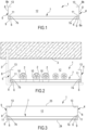
- the invention concerns a structure 1 for supporting cables and/or pipes, e.g. usable in the civil and/or industrial fields for supporting and/or routing electrical cables, optical cables, cables of other nature, pipes, and the like, indicated with reference 2 in Figures 2 and 4 .
- the support structure 1 may, for example, be tied to the ceiling 3 of a building (e.g., by means of one or more brackets 3' or other attachment means such as cables or the like) and thus being arranged to extend horizontally and distanced from the ceiling itself.
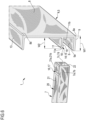
- the support structure 1 includes a first and a second profile 4 and 5 longitudinally side by side which each other. As previously mentioned, the profiles are arranged to extend horizontally, however, in further use conditions they could be tied to a vertical wall.
- profiles 4 and 5 faces the opposing profile and defines a respective anchoring seat 6 facing the anchoring seat 6 of the other of said profiles: as will be seen later in the description, profiles 4 and 5 may have mirror shapes and in any case each include respective parts similar to those of the other profile.
- Profiles 4 and 5 are constrained to each other by a plurality of crossties 7 terminally engaged to the first and second profiles 4 and 5: the crossties 7 shown in the accompanying figures, are all geometrically equal to each other; these crossties are transversally engaged to profiles 4 and 5 and they are transversely spaced apart from each other with respect to the first and second profiles.
- the currently preferred solution is for the support structure 2 to have the first and second profiles 4 and 5 arranged parallel to each other: in practice, the first profile extends along a first longitudinal direction of prevalent development and the second profile extends parallel to the first profile along a second longitudinal direction of prevalent development parallel to the first direction, with the crossties equally spaced with each other and arranged perpendicular to the profiles 4 and 5.
- cables or pipes or other elongated bodies that may be supported by the structure 1 may simply be resting on the crossties 7 or may be constrained to the crossties for example by clamps 10.
- the first and second profiles are made, preferably by a pultrusion process, of composite material: each profile thus includes a plastic resin matrix in which fibers of reinforcing material are embedded. Thanks to the pultrusion process, the reinforcing fibers are continuous and extend full length along the entire longitudinal development of the profiles: these fibers are directed parallel to each other along the longitudinal extension of the respective profile.
- the plastic resin matrix is actually made of a polymer resin that includes at least one thermosetting resin and/or one thermoplastic resin; in particular the polymer resin includes at least one selected from the group of the following materials: polyester, epoxy resin, acrylic resin, vinyl ester, phenolic resin, PVC, polyurethane, polyethylene.
- Reinforcing fibers can be selected from: glass fibers, carbon fibers, synthetic fibers, basalt fibers.
- reinforcing fibers are present within the resin in a weight percentage greater than 40%, specifically in a weight percentage comprised between 40% percent and 90%, preferably around 60%.
- Crossties 7 can also be made of a pultruded profile by using the above-described materials (plastic matrix + fibers) in connection with the profiles 4 and 5.
- the pultruded profile intended for forming the crossties 7 will then be transversally cut and machined for making the grooves described in the following.
- the materials described above give to the profiles 4 and 5 and to the sleepers 7 excellent mechanical properties and excellent thermal and electrical insulation properties.
- the profiles 4 and 5 are geometrically mirrored, each comprising a main wall 8, which in the case exemplified in the drawings, is a flat wall of constant thickness. From the main wall of each profile 4 and 5 emerges a base wall 9 directed transversely, and preferably orthogonally, to the main wall: as shown in the drawings the base wall 9 extends from a longitudinal edge 8a (which in the figures is a lower longitudinal edge) of the main wall.
- an auxiliary wall 11 also extends emerging transversely from the main wall (and preferably parallel to the base wall 9 and thus orthogonal to the main wall 8).
- the auxiliary wall 11 is arranged at a predetermined distance from the base wall so as to form, in cooperation with the base wall, the aforementioned anchoring seat 6 for the crossties 7.
- the main wall 8 of each of the first and second profiles extends beyond the auxiliary wall 11, on the opposite side from the base wall, to define, in cooperation with the crossties 7 a housing compartment 12 for cables and/or pipes and/or other elongated bodies.
- the housing compartment 12 is arranged, in the condition of ceiling use of the structure 1 (see Figure 2 ), over the crossties themselves and, therefore, above the anchoring seats 6 where the ends of the crossties engage.
- Each of the profiles 4 and 5 also includes a top wall 13 emerging transversely from the main wall 8, on the same flank of the profile having the base wall 9 and auxiliary wall 11.
- the top wall 13 emerges from a longitudinal top edge 8b, opposed to edge 8a, of the main wall 8 and is arranged perpendicular to the main wall 8 and then parallel to the base wall 9 and the auxiliary wall 11 of each profile.
- the top wall 13, the auxiliary wall 11 and the base wall 9 of each profile 4 and 5 extend on the same flank of each profile and are directed toward each other of said first and second profiles 4 and 5.
- the base wall 9 and optionally the top wall 13, extend according to an equal width W1 transversely to the main wall 8, while the auxiliary wall 11 extends transversely to the main wall 8 according to a width W2 that is slightly lower than the width of the base wall 8a.
- the main wall 8, base wall 9 and auxiliary wall 11 of each profile 4 and 5 extend the full length of the respective first and second profiles.
- the base wall 9 and the auxiliary wall 11 both have a constant cross-sectional profile throughout the longitudinal development respectively of the first and second profiles 4, 5.
- the auxiliary wall 11 is interposed between the base wall 9 and the top wall 11, and in particular is significantly closer to the base wall 9 than to the top wall 13, so that the size of the anchoring seat 6 is significantly smaller than the size of the compartment 12 housing cables and/or pipes.
- each crosstie 7 has a first end 7a inserted into the anchoring seat 6 of the first profile 4 and a second end 7b, opposite to the first end, inserted into the anchoring seat 6 of the second profile 5.
- each of the crossties 7 forms, at the anchoring seat 6 on the first profile 4, a mechanical interfering engagement with at least one of the base wall 9 and the auxiliary wall 11 of the first profile.
- the auxiliary wall 11 of the first profile has a respective first stop projection 14 emerging inward from the respective anchoring seat 6 on the first profile.
- the first end 7a of each of the crosstie has in turn at least one shaped portion cooperating with the first stop projection that engages with the shaped portion and forms a stable mechanical coupling between the end 7a of the crosstie and the anchoring seat and thus the first profile 4.
- each crosstie 7 forms, at the anchoring seat 6 on the second profile 5, a mechanical interfering engagement with at least one of the base wall 9 and the auxiliary wall 11 of the second profile.
- the auxiliary wall 11 of the second profile has a second stop projection 15 emerging inward from the respective anchoring seat 6 on the second profile 5.
- the second end 7b of each of the crossties 7 has in turn at least one shaped portion cooperating with the second stop projection 15 that engages with the shaped portion and forms a stable mechanical coupling between the end 7b of the crosstie and the anchoring seat and thus the first profile 4.
- the shaped portion of the first end 7a of each of the crossties 7 includes a first groove 16 parallel to a longitudinal development direction of the first stop projection 14, while the shaped portion of the second end 7b of each of the crossties includes a second groove 17 parallel to a longitudinal development direction of the second stop projection 15.
- first stop projection 14 extends along the auxiliary wall 11 of the first profile, in particular, it continuously extends along the entire auxiliary wall of the first profile 4, straight and parallel to the first longitudinal direction of prevalent development of the first profile itself; similarly, the second stop projection 15 extends along the auxiliary wall 11 of the second profile 5, in particular extending continuously along the entire auxiliary wall of the second profile, straight and parallel to the first longitudinal direction of prevalent development of the second profile itself.
- each crosstie 7 can be coupled at any longitudinal position along the first and second profiles 4 and 5, simply by engaging the end portions 7a, 7b of each crosstie in the respective anchoring seat 6.
- each stop projection 14 and 15 (which are identical in the example shown) includes a respective guide portion 18 that emerges from the end edge 11a of the auxiliary wall of the first profile 4 or from the second profile.
- the guide portion 18 has increasing, in particular linearly increasing, thickness proceeding from the end edge 11a of the auxiliary wall 11 and proceeding towards the main wall 8 of the profile.
- Each of the projections 14 and 15 also has a respective clamping portion 19, consecutive to the guide portion 18 and insertable into the first groove 16 (or the second groove 17).
- the clamping portion 19 has a step portion having variable thickness, increasing proceeding internally towards anchoring seat 6 to define an undercut that prevents the removal of the projections 14, 15 when coupled with the respective groove 16, 17.
- first and second projections 14 and 15 both have a constant cross-section profile throughout the longitudinal development respectively of the first and second profile 4, 5.
- the first groove and second grooves 16, 17 of each crosstie extend full width on a same side 20 of the crosstie 7, for allowing both stop teeth 14 and 15 to be easily inserted into their respective grooves during assembly.
- each crosstie 7 has, at least at the first end 7a, a planar flank 21 over which the first groove 15 extends, which runs across the whole of the same plane flank of the crosstie parallel to the direction of longitudinal development of the first projection.
- each crosstie has, at least at the second end 7b, a similar flat flank 21 (co-planar or coincident with the flat flank where the first groove is arranged) over which extends the second groove 16, which runs through the entire flat flank of the crosstie parallel to the direction of longitudinal development of the second projection.
- the flatness of the flank 21 of the crosstie at least at the ends 7a and 7b (and preferably along the entire length of the crosstie) allows, once the ends 7a and 7b of the crosstie 7 have been engaged in their respective seats 6, to have a flat abutting surface with a lower surface 11b, also flat, of the auxiliary wall of each profile.
- the contact between the lower surface 11b of the auxiliary wall 11 with the crosstie, and in particular with the first or second flat facet 21a, 21b described below, allows frictional forces to arise between the lower surface 11b and the crosstie, such that to limit the relative displacement between profile and crosstie and strengthening the coupling even in the presence of vertical loads applied on the crosstie 7.
- each crosstie 7 is in the form of a tubular profile (on which grooves 14 and 15 are manufactured by means of material removal or hot deformation) with a polygonal cross-section, optionally having square or rectangular profile, so that the crosstie itself has flat faces transversal to each other that fit terminally into the respective seat 6 with a respective bottom face 7c, 7d of each crosstie that optionally acts abutting against a flat inner surface of the main wall 8.
- Each crosstie also has, at least at each end 7a, 7b, a further flat flank 22 opposite to the flat flank 21, on which the first and second grooves 16, 17 extend.
- the flatness of the further flat flank 22 of the crosstie allows, once the ends 7a and 7b of the crosstie 7 have been engaged in their respective anchoring seats 6, to have a flat abutting surface with an upper surface 9a of a respective base wall 9 of the first and second profiles 4, 5.
- the upper surface 9a of the base walls 9 of the first and second profiles has an entirely flat surface facing the auxiliary wall of the respective first and second profiles 4, 5.
- each base wall 9 is devoid of protuberances emerging from a respective upper surface 9a directed towards the anchoring seat 6.
- each crosstie 7 has at the first end 7a, opposing flat flanks 21, 22 contacting respectively a flat lower surface 11b of auxiliary wall 11 and an upper surface 9a entirely flat of the base wall 9 of the first profile 4.
- each crosstie 7 has at the second end 7b, opposing flat flanks 21, 22 contacting respectively a lower surface 11b of auxiliary wall 11 and an upper surface 9a of the base wall of the second profile 5.
- a base walls 9 having respective upper surfaces 9a entirely flat and facing a respective auxiliary wall 11 on which a stop projection is defined has the dual effect of allowing a snap engagement between a crosstie and any portion of the profile, as well as of maximizing the contact area between the profile and the crosstie in order to reduce any relative displacement between the two.
- Such feature gives the support structure a high degree of rigidity and flexibility of use, as the entirely flat upper surface 9a allows the crossties to be positioned between them at any distance selectable by the user and not constrained by the specific construction structure of profiles and crossties.
- each crosstie 7 has the respective first groove 16 arranged perpendicular to the main development direction of the crosstie itself (and parallel to the development direction of the first projection placed on the first profile) and the first bottom face 7c placed in a plane perpendicular to the main development direction of the crosstie itself.
- a first flat facet 21a is thus defined adjacent to the first groove 16 and extending between the first groove itself and the first bottom face 7c.
- such first flat facet 21a contacts the bottom surface 11b of the auxiliary wall of the first profile 4 and fits at a first strip of such bottom surface 11b arranged between the first projection 14 and the main wall 8.
- each crosstie has the second groove arranged 17 perpendicular to the main development direction of the crosstie itself (and parallel to the development direction of the second projection 15 placed on the second profile 5), with the second end face 7d, opposed to the first end face 7c of the same crosstie 7, arranged in a plane perpendicular to the main development direction of the crosstie itself.
- a second flat facet 21b adjacent to the second groove 17 and extending between the second groove itself and the second end face 7d.
- the second flat facet is positioned in contact with the lower surface 11b of the auxiliary wall of the second profile 5, at a second strip of the lower surface, between the second projection 15 and the main wall 8.
- the lateral extension of the first facet 21a measured perpendicular to the first bottom face 7c of each crosstie, is substantially equal to the width of the first strip and, similarly, the lateral extension of the second facet 21b, measured perpendicular to the second bottom face 7d of each crosstie, is substantially equal to the width of the second strip.
- the structure 1 may include a lower cover 23 and/or an upper cover 24 constrained to structure 1 and in particular to the profiles 4 and 5 so as to close or protect the compartment 12.
- the first and second profiles are made by pultrusion, for example, using the plastic resin matrix and reinforcing fibers described above.
- Crossties are also (before, after or simultaneously) made, which are then terminally joined to the two profiles 4 and 5.
- the crossties 7 may also be defined by a profile manufactured in the materials described above (plastic matrix and fibers) obtained by pultrusion.
- the pultruded profile intended for the formation of crossties 7 will then be transversally cut and machined to form the grooves 16 and 17, which may be obtained by material removal (e.g., by milling) or by hot deformation of the areas where the grooves are to be formed.
- the grooves may be alternately made before transversally cutting the pultruded semifinished product that will form the crossties 7.
- first and second projections 14 and 15 snap into the first and second grooves 16 and 17 respectively, while the first and second facets 21a and 2b abut against the lower surface 11b of auxiliary wall 11.
- the first and second ends of the crossties are not glued with the first and second profiles respectively.
- first and second ends 7a, 7b of the crossties are not engaged at the first and second profiles 4 and 5 respectively, by additional mechanical means (additional to the composite components described above, i.e., crossties and profiles) such as screws, bolts, nails or rivets, metal or composite pins.
- additional mechanical means such as screws, bolts, nails or rivets, metal or composite pins.
- screws or bolts or rivets or other may additionally be used one or more of screws or bolts or rivets or other for further strengthening the crosstie-profile coupling.
- An installation process may involve constraining the support structure to a ceiling or a wall of a building, so that the first and second profiles 4 and 5 extend horizontally with the anchoring seat 6 arranged in a lower area of the first and second profiles themselves.
- cables and/or pipes can be placed over the crossties 7, and then loaded on the structure 1, so that the weight of said cables and/or pipes, tend to bend each of said crossties, pushing in further engagement said first and second projections 14 and 15 into the respective first and second grooves 16 and 17 of each crosstie 7.
- the lower cover 23 and/or the upper cover 24 can be affixed: such cover(s) can be constrained to the structure 1 and in particular to the profiles 4 and 5, e.g. by mechanical locking or gluing, so as to close and/or protect the compartment 12.
Landscapes
- Engineering & Computer Science (AREA)
- General Engineering & Computer Science (AREA)
- Architecture (AREA)
- Civil Engineering (AREA)
- Structural Engineering (AREA)
- Mechanical Engineering (AREA)
- Supports For Pipes And Cables (AREA)
- Laying Of Electric Cables Or Lines Outside (AREA)
- Details Of Indoor Wiring (AREA)
- Connection Of Plates (AREA)
- Mutual Connection Of Rods And Tubes (AREA)
Claims (13)
- Halterungsstruktur für Kabel und/oder Rohre, umfassend:- ein erstes und ein zweites Profil (4, 5), welche longitudinal nebeneinander angeordnet sind, wobei jedes der Profile (4, 5) wenigstens einen jeweiligen Verankerungssitz (6) definiert, welcher dem Verankerungssitz (6) des anderen der Profile (4, 5) zugewandt ist;- eine Mehrzahl von Querverbindungen (7), welche in das erste und das zweite Profil (4, 5) eingreifen, wobei die Querverbindungen (7) voneinander beabstandet sind und transversal zu dem ersten und dem zweiten Profil (4, 5) angeordnet sind;wobei jede der Querverbindungen (7) ein erstes Ende (7a), welches in den Verankerungssitz (6) des ersten Profils (4) eingesetzt ist, und ein zweites Ende (7b) aufweist, welches dem ersten Ende (7a) entgegengesetzt ist, welches in den Verankerungssitz (6) des zweiten Profils (5) eingesetzt ist;wobei jedes des ersten und des zweiten Profils (4, 5) umfasst:- eine Hauptwandung (8),- eine Grundwandung (9), welche von der Hauptwandung (8) transversal vorsteht, und- eine Hilfswandung (11), welche ebenso aus der Hauptwandung (8) transversal hervorgeht, an einer vorbestimmten Distanz von der Grundwandung (9), wo die Hilfswandung (11) mit der Grundwandung (9) kooperiert, um den Verankerungssitz (6) zu definieren;wobei:- die Hilfswandung (11) des ersten Profils (4) einen entsprechenden ersten Haltevorsprung (14) aufweist, welcher nach innen von dem Verankerungssitz (6) hervorgeht, an dem ersten Profil (4), wobei das erste Ende (7a) jeder der Querverbindungen (7) wenigstens einen geformten Abschnitt aufweist, welcher mit dem entsprechenden ersten Haltevorsprung (14) kooperiert;- die Hilfswandung (11) des zweiten Profils (5) einen zweiten Haltevorsprung (15) aufweist, welcher nach innen von dem Verankerungssitz (6) hervorgeht, an dem zweiten Profil (5), wobei das zweite Ende (7b) jeder der Querverbindungen (7) wenigstens einen geformten Abschnitt aufweist, welcher mit dem zweiten Haltevorsprung (15) kooperiert;wobei:- der geformte Abschnitt des ersten Endes (7a) jeder der Querverbindungen (7) eine erste Nut (16) umfasst, welche parallel zu einer longitudinalen Entwicklungsrichtung des ersten Haltevorsprungs (14) ist; und- der geformte Abschnitt des zweiten Endes (7b) jeder der Querverbindungen (7) eine zweite Nut (17) umfasst, welche parallel zu einer longitudinalen Entwicklungsrichtung des zweiten Haltevorsprungs (15) ist,dadurch gekennzeichnet, dassjede Querverbindung (7) in der Form eines rohrförmigen Profils ist, welches einen polygonalen Querschnitt aufweist, wobei jede Querverbindung (7) aufweist:- an dem ersten Ende (7a), entgegengesetzte ebene Flanken (22), welche jeweils eine untere Fläche der Hilfswandung (11) und eine obere Fläche der Grundwandung (9) des ersten Profils (4) kontaktieren; und- an dem zweiten Ende (7b), entgegengesetzte ebene Flanken (22), welche jeweils eine untere Fläche der Hilfswandung (11) und eine obere Fläche der Grundwandung (9) des zweiten Profils (5) kontaktieren;und wobei:- die obere Fläche (9a) der Grundwandung (9) des ersten Profils (4) vollkommen eben ist und mit der ebenen Flanke (22) des ersten Endes (7a) der Querverbindung (7) in Kontakt steht, welche der Grundwandung (9) des ersten Profils (4) zugewandt ist; und- die obere Fläche (9a) der Grundwandung (9) des zweiten Profils (5) mit der ebenen Flanke (22) des zweiten Endes (7b) der Querverbindung (7) in Kontakt steht, welche der Grundwandung (9) des zweiten Profils (5) zugewandt ist.
- Halterungsstruktur nach Anspruch 1, wobei sich das erste Profil (4) entlang einer ersten longitudinalen Richtung einer vorwiegenden Entwicklung erstreckt und wobei sich das zweite Profil (5) parallel zu dem ersten Profil (4) entlang einer zweiten longitudinalen Richtung einer vorwiegenden Entwicklung erstreckt; und wobei sich die Hauptwandung (8), die Grundwandung (9) und die Hilfswandung (11) jedes Profils vollständig über das entsprechende erste und zweite Profil (4, 5) erstrecken.
- Halterungsstruktur nach Anspruch 1 oder 2, wobei:- das erste Ende (7a) jeder der Querverbindungen (7) an dem Verankerungssitz (6) an dem ersten Profil (4) einen mechanischzusammenwirkenden Eingriff mit wenigstens einer aus der Grundwandung (9) und der Hilfswandung (11) des ersten Profils (4) bildet; und- das zweite Ende (7b) jeder der Querverbindungen (7) an dem Verankerungssitz (6) an dem zweiten Profil (5) einen mechanischzusammenwirkenden Eingriff mit wenigstens einer aus der Grundwandung (9) und der Hilfswandung (11) des zweiten Profils (5) bildet.
- Halterungsstruktur nach Anspruch 1, wobei:- sich der erste Haltevorsprung (14) entlang der Hilfswandung (11) des ersten Profils (4) erstreckt, kontinuierlich entlang der ganzen Hilfswandung (11) des ersten Profils (4), in einer geradlinigen Weise und parallel zu der ersten longitudinalen Richtung einer vorwiegenden Entwicklung des ersten Profils (4) selbst;- sich der zweite Haltevorsprung (15) entlang der Hilfswandung (11) des zweiten Profils (5) erstreckt, kontinuierlich entlang der ganzen Hilfswandung (11) des zweiten Profils (5), in einer geradlinigen Weise und parallel zu der ersten longitudinalen Richtung einer vorwiegenden Entwicklung des zweiten Profils (5) selbst.
- Halterungsstruktur nach Anspruch 1 oder 4, wobei:- der erste Haltevorsprung (14) aus einem Endrand der Hilfswandung (11) des ersten Profils (4) hervorgeht; und- der zweite Haltevorsprung (15) aus einem Endrand der Hilfswandung (11) des zweiten Profils (5) hervorgeht;wobei ferner- der erste Vorsprung (14) umfasst:- einen entsprechenden Führungsabschnitt (18), welcher sich von dem Endrand der Hilfswandung (11) des ersten Profils (4) erstreckt und eine ansteigende, insbesondere linear ansteigende, Dicke aufweist, welche von dem Endrand der Hilfswandung (11) zu der Hauptwandung (8) des ersten Profils (4) verläuft, und- einen entsprechenden Klemmabschnitt (19), welcher auf den Führungsabschnitt (18) folgt und vorgesehen ist, um in die erste Nut (16) einzurasten, wobei der Klemmabschnitt (19) einen Dickenvariation definiert, welche als eine Stufe in der Hilfswandung (11) des ersten Profils (4) geformt ist; und- der zweite Vorsprung (15) umfasst:- einen entsprechenden Führungsabschnitt (18), welcher sich von dem Endrand der Hilfswandung (11) des zweiten Profils (5) erstreckt und eine ansteigende, insbesondere linear ansteigende, Dicke aufweist, welche von dem Endrand der Hilfswandung (11) zu der Hauptwandung (8) des zweiten Profils (5) verläuft, und- einen entsprechenden Klemmabschnitt (19), welcher auf den Führungsabschnitt (18) folgt und vorgesehen ist, um in die zweite Nut (17) einzurasten, wobei der Klemmabschnitt (19) einen Dickenvariation definiert, welche als eine Stufe in der Hilfswandung (11) des zweiten Profils (5) geformt ist.
- Halterungsstruktur nach einem der vorhergehenden Ansprüche, wobei jedes des ersten und des zweiten Profils (4, 5) dafür sorgt, dass, in einem Querschnitt, sich die entsprechende Hauptwandung (8) über die Hilfswandung (11) hinaus an der entgegengesetzten Seite mit Bezug zu der Grundwandung (9) erstreckt, um, in Kooperation mit den Querverbindungen (7), ein Gehäuseraum (12) für die Kabel und/oder Rohre zu definieren, welche, in einem Zustand einer Deckennutzung der Struktur, über den Querverbindungen (7) positioniert sind;und wobei jedes des ersten und des zweiten Profils (4, 5) eine Oberwandung (13) umfasst, welche transversal aus der Hauptwandung (8) hervorgeht, optional aus einem longitudinalen Oberrand der Hauptwandung (8), und wobei sich die Oberwandung (13), die Hilfswandung (11) und die Grundwandung (9) von jedem des ersten und des zweiten Profils (5) in Richtung des anderen des ersten und des zweiten Profils (4, 5) erstrecken;wobei insbesondere sich die Oberwandung, die Hilfswandung (11) und die Grundwandung (9) von jedem des ersten und des zweiten Profils (4, 5) senkrecht zu und an der gleichen Seite von der Hauptwandung (8) erstrecken.
- Halterungsstruktur nach einem der vorhergehenden Ansprüche, wobei sich die erste Nut (16) jeder Querverbindung (7) über die gesamte Breite auf einer Seite der Querverbindung (7) erstreckt, und wobei sich die zweite Nut (17) jeder Querverbindung (7) über die gesamte Breite auf der gleichen Seite der Querverbindung (7) selbst erstreckt;in welcher jede Querverbindung (7), wenigstens an dem ersten Ende (7a), eine ebene Flanke aufweist, an welcher sich die erste Nut (16) erstreckt, welche die gesamte ebene Flanke der Querverbindung (7) durchquert, welche parallel zu der Richtung einer longitudinalen Entwicklung des ersten Vorsprungs (14) ist;und in welcher jede Querverbindung (7), wenigstens in Entsprechung mit dem zweiten Ende (7b), eine ebene Flanke aufweist, an welcher sich die zweite Nut (17) erstreckt, welche die gesamte ebene Flanke der Querverbindung (7) durchquert, welche parallel zu der Richtung einer longitudinalen Entwicklung des zweiten Vorsprungs (15) ist.
- Halterungsstruktur nach einem der vorhergehenden Ansprüche, wobei das erste Ende (7a) jeder Querverbindung (7) aufweist:- die erste Nut (16), welche senkrecht zu der Hauptentwicklungsrichtung der Querverbindung (7) selbst angeordnet ist und parallel zu der Entwicklungsrichtung des ersten Vorsprungs (14) ist, welcher an dem ersten Profil (4) platziert ist,- eine erste Endfläche, welche in einer Ebene senkrecht zu der Hauptentwicklungsrichtung der Querverbindung (7) selbst platziert ist,- eine erste ebene Facette, welche der ersten Nut (16) benachbart ist und sich zwischen der ersten Nut (16) und der ersten Endfläche erstreckt, wobei die erste ebene Facette mit der unteren Fläche der Hilfswandung (11) des ersten Profils (4) in Kontakt positioniert ist, an einem ersten Streifen der unteren Fläche zwischen dem ersten Vorsprung (14) und der Hauptwandung (8),und wobei das zweite Ende (7b) jeder Querverbindung (7) aufweist:- die zweite Nut (17), welche senkrecht zu der Hauptentwicklungsrichtung der Querverbindung (7) selbst angeordnet ist und parallel zu der Entwicklungsrichtung des zweiten Vorsprungs (15) ist, welcher an dem zweiten Profil (5) platziert ist,- eine zweite Endfläche, entgegengesetzt der ersten Endfläche der gleichen Querverbindung (7), welche in einer Ebene senkrecht zu der Hauptentwicklungsrichtung der Querverbindung (7) selbst platziert ist,- eine zweite ebene Facette, welche der zweiten Nut (17) benachbart ist und sich zwischen der zweiten Nut (17) und der zweiten Endfläche erstreckt, wobei die zweite ebene Facette mit der unteren Fläche der Hilfswandung (11) des zweiten Profils (5) in Kontakt positioniert ist, übereinstimmend mit einem zweiten Streifen der unteren Fläche zwischen dem zweiten Vorsprung (15) und der Hauptwandung (8),wobei die seitliche Erstreckung der ersten Facette, welche senkrecht zu der ersten Endfläche jeder Querverbindung (7) gemessen ist, im Wesentlichen gleich zu der Breite des ersten Streifens ist, undwobei die seitliche Erstreckung der zweiten Facette, welche senkrecht zu der zweiten Endfläche jeder Querverbindung (7) gemessen ist, im Wesentlichen gleich zu der Breite des zweiten Streifens ist.
- Halterungsstruktur nach einem der vorhergehenden Ansprüche, wobei jedes von dem ersten und dem zweiten Profil (4, 5) durch ein Ziehen von einem Verbundmaterial hergestellt ist, welches eine Kunststoffharzmatrix umfasst, in welcher Fasern von verstärktem Material eingebettet sind, welche entlang der longitudinalen Erstreckung des Profils gerichtet sind;
wobei jede der Querverbindungen durch Ziehen von einem Verbundmaterial hergestellt ist, welches eine Kunststoffharzmatrix umfasst, in welcher Fasern von verstärktem Material eingebettet sind, welche entlang der longitudinalen Erstreckung der Querverbindung (7) gerichtet sind und daher transversal, insbesondere senkrecht, zu der longitudinalen Erstreckung jedes von dem ersten und dem zweiten Profil (4, 5) sind. - Halterungsstruktur nach einem der vorhergehenden Ansprüche, wobei die Grundwandungen (9) des ersten und des zweiten Profils (4, 5) jeweilige obere Flächen (9a) aufweisen, welche der Hilfswandung (11) vollständig eben zugewandt sind und mit einer entsprechenden ebenen Flanke der Querverbindungen in Kontakt stehen, wobei jede Grundwandung (9) des ersten und des zweiten Profils (4, 5) keine Protuberanzen aufweist, welche von der oberen Fläche (9a) der entsprechenden Grundwandung (9) des ersten und des zweiten Profils (4, 5) hervorgehen.
- Halterungsstruktur nach dem vorhergehenden Anspruch, wobei jede Hilfswandung (11) des entsprechenden ersten und des zweiten Profils (4, 5) eine untere Fläche (11b) aufweist, welche zwischen dem entsprechenden ersten und zweiten Vorsprung (14, 15) und der Hauptwandung (8) des entsprechenden ersten und zweiten Profils (4, 5) eingefügt ist,wobei die untere Fläche (11b) der Hilfswandung des ersten Profils (4) vollständig eben ist und mit einer ebenen Flanke (21) des ersten Endes (7a) der Querverbindung (7) in Kontakt steht, welche der Hilfswandung (11) des ersten Profils (4) zugewandt ist,wobei die untere Fläche (11b) der Hilfswandung des zweiten Profils (5) vollständig eben ist und mit einer ebenen Flanke (21) des zweiten Endes (7b) der Querverbindung (7) in Kontakt steht, welche der Hilfswandung (11) des zweiten Profils (5) zugewandt ist.
- Verfahren zum Herstellen einer Halterungsstruktur nach einem der Ansprüche 1 bis 11, umfassend:- Herstellen durch ein Ziehverfahren des ersten und des zweiten Profils (4, 5);- Verkoppeln der ersten Enden einer Mehrzahl von Querverbindungen (7) mit dem Verankerungssitz (6) des ersten Profils (4) und der zweiten Enden der Mehrzahl von Querverbindungen (7) mit dem Verankerungssitz (6) des zweiten Profils (5), um das erste und das zweite Profil (4, 5) parallel zueinander und die Querverbindungen (7) voneinander beabstandet entlang der longitudinalen Entwicklung des ersten und des zweiten Profils (4, 5) anzuordnen.
- Verfahren nach Anspruch 12, wobei das erste und das zweite Ende der Querverbindungen (7) mit dem ersten oder dem zweiten Profil (4, 5) weder verklebt sind noch sind sie in das erste oder das zweite Profil (4, 5) durch weitere mechanische Mittel, zusätzlich zu den Querverbindungen und den Profilen, eingegriffen.
Applications Claiming Priority (1)
| Application Number | Priority Date | Filing Date | Title |
|---|---|---|---|
| IT102021000027158A IT202100027158A1 (it) | 2021-10-22 | 2021-10-22 | Struttura di supporto per cavi e/o tubi |
Publications (3)
| Publication Number | Publication Date |
|---|---|
| EP4170214A1 EP4170214A1 (de) | 2023-04-26 |
| EP4170214B1 true EP4170214B1 (de) | 2025-04-02 |
| EP4170214C0 EP4170214C0 (de) | 2025-04-02 |
Family
ID=79269837
Family Applications (1)
| Application Number | Title | Priority Date | Filing Date |
|---|---|---|---|
| EP22197760.6A Active EP4170214B1 (de) | 2021-10-22 | 2022-09-26 | Tragstruktur für kabel und/oder rohre und verfahren zu deren herstellung |
Country Status (3)
| Country | Link |
|---|---|
| EP (1) | EP4170214B1 (de) |
| ES (1) | ES3028802T3 (de) |
| IT (1) | IT202100027158A1 (de) |
Family Cites Families (3)
| Publication number | Priority date | Publication date | Assignee | Title |
|---|---|---|---|---|
| US3915420A (en) * | 1974-10-07 | 1975-10-28 | Crouse Hinds Co | Cable tray |
| BE1002629A6 (nl) * | 1988-12-05 | 1991-04-16 | Bekaert Sa Nv | Kabelladder. |
| ES1126630Y (es) * | 2014-09-25 | 2015-09-03 | Unex Aparellaje Electrico Sl | Escalera portacables |
-
2021
- 2021-10-22 IT IT102021000027158A patent/IT202100027158A1/it unknown
-
2022
- 2022-09-26 ES ES22197760T patent/ES3028802T3/es active Active
- 2022-09-26 EP EP22197760.6A patent/EP4170214B1/de active Active
Also Published As
| Publication number | Publication date |
|---|---|
| ES3028802T3 (en) | 2025-06-20 |
| EP4170214A1 (de) | 2023-04-26 |
| EP4170214C0 (de) | 2025-04-02 |
| IT202100027158A1 (it) | 2023-04-22 |
Similar Documents
| Publication | Publication Date | Title |
|---|---|---|
| RU2406809C2 (ru) | Механическое соединение в замок панелей пола с гибким щетинистым гребнем | |
| RU2446260C2 (ru) | Механическое блокирование панелей перекрытия | |
| CA1090639A (en) | Guard-rails assembly | |
| CA2443022C (en) | Panel assembly for joining flat, thin members that adjoin each other | |
| US8402707B2 (en) | Interlocking panel system | |
| US6672026B2 (en) | Pultruded I-bar with clip fittings enabling automated grating panel assembly | |
| JP5237769B2 (ja) | 異形材レールシステム | |
| US9279261B2 (en) | Method for manufacturing a formwork element | |
| US20160340910A1 (en) | Floating floor system, floor panel, and installation method for the same | |
| US11180915B2 (en) | Longspan stay-in-place liners | |
| AU2019202881B2 (en) | Decking or flooring system, and components therefor | |
| US20130255174A1 (en) | Siding joinery | |
| US20140134394A1 (en) | Void containing structural member | |
| US4319724A (en) | Lightweight cable ladder | |
| EP4170214B1 (de) | Tragstruktur für kabel und/oder rohre und verfahren zu deren herstellung | |
| EP3243976B1 (de) | Plattenspleissverbinder für lineare deckenplatten | |
| JP2008512613A (ja) | 引き抜き形状成形された2つのパネルを結合する方法およびそのための拘束用接続金具 | |
| EP4033056B1 (de) | Verbindungsstange für fensterbeschlag | |
| RU2779864C2 (ru) | Система соединения для панелей напольного настила | |
| RU2779864C9 (ru) | Система соединения для панелей напольного настила | |
| JP6832637B2 (ja) | たわみ防止金具並びにたわみ防止金具を用いた金属製床パネルの補強工法および補強構造 | |
| WO1996010119A1 (en) | A panel of extruded profile elements | |
| JP2009197518A (ja) | グレーチング | |
| HK1128314B (en) | Profiled rail system | |
| CA2816294A1 (en) | Siding joinery |
Legal Events
| Date | Code | Title | Description |
|---|---|---|---|
| PUAI | Public reference made under article 153(3) epc to a published international application that has entered the european phase |
Free format text: ORIGINAL CODE: 0009012 |
|
| STAA | Information on the status of an ep patent application or granted ep patent |
Free format text: STATUS: THE APPLICATION HAS BEEN PUBLISHED |
|
| AK | Designated contracting states |
Kind code of ref document: A1 Designated state(s): AL AT BE BG CH CY CZ DE DK EE ES FI FR GB GR HR HU IE IS IT LI LT LU LV MC MK MT NL NO PL PT RO RS SE SI SK SM TR |
|
| P01 | Opt-out of the competence of the unified patent court (upc) registered |
Effective date: 20230529 |
|
| STAA | Information on the status of an ep patent application or granted ep patent |
Free format text: STATUS: REQUEST FOR EXAMINATION WAS MADE |
|
| 17P | Request for examination filed |
Effective date: 20231023 |
|
| RAX | Requested extension states of the european patent have changed |
Extension state: ME Payment date: 20231023 Extension state: BA Payment date: 20231023 |
|
| RBV | Designated contracting states (corrected) |
Designated state(s): AL AT BE BG CH CY CZ DE DK EE ES FI FR GB GR HR HU IE IS IT LI LT LU LV MC MK MT NL NO PL PT RO RS SE SI SK SM TR |
|
| GRAP | Despatch of communication of intention to grant a patent |
Free format text: ORIGINAL CODE: EPIDOSNIGR1 |
|
| STAA | Information on the status of an ep patent application or granted ep patent |
Free format text: STATUS: GRANT OF PATENT IS INTENDED |
|
| RIC1 | Information provided on ipc code assigned before grant |
Ipc: H02G 3/04 20060101ALI20241011BHEP Ipc: F16L 3/26 20060101AFI20241011BHEP |
|
| INTG | Intention to grant announced |
Effective date: 20241023 |
|
| GRAS | Grant fee paid |
Free format text: ORIGINAL CODE: EPIDOSNIGR3 |
|
| GRAA | (expected) grant |
Free format text: ORIGINAL CODE: 0009210 |
|
| STAA | Information on the status of an ep patent application or granted ep patent |
Free format text: STATUS: THE PATENT HAS BEEN GRANTED |
|
| AK | Designated contracting states |
Kind code of ref document: B1 Designated state(s): AL AT BE BG CH CY CZ DE DK EE ES FI FR GB GR HR HU IE IS IT LI LT LU LV MC MK MT NL NO PL PT RO RS SE SI SK SM TR |
|
| REG | Reference to a national code |
Ref country code: GB Ref legal event code: FG4D |
|
| REG | Reference to a national code |
Ref country code: CH Ref legal event code: EP |
|
| REG | Reference to a national code |
Ref country code: IE Ref legal event code: FG4D |
|
| REG | Reference to a national code |
Ref country code: DE Ref legal event code: R096 Ref document number: 602022012505 Country of ref document: DE |
|
| U01 | Request for unitary effect filed |
Effective date: 20250429 |
|
| U07 | Unitary effect registered |
Designated state(s): AT BE BG DE DK EE FI FR IT LT LU LV MT NL PT RO SE SI Effective date: 20250507 |
|
| P04 | Withdrawal of opt-out of the competence of the unified patent court (upc) registered |
Free format text: CASE NUMBER: APP_20772/2025 Effective date: 20250430 |
|
| REG | Reference to a national code |
Ref country code: ES Ref legal event code: FG2A Ref document number: 3028802 Country of ref document: ES Kind code of ref document: T3 Effective date: 20250620 |
|
| PG25 | Lapsed in a contracting state [announced via postgrant information from national office to epo] |
Ref country code: NO Free format text: LAPSE BECAUSE OF FAILURE TO SUBMIT A TRANSLATION OF THE DESCRIPTION OR TO PAY THE FEE WITHIN THE PRESCRIBED TIME-LIMIT Effective date: 20250702 Ref country code: GR Free format text: LAPSE BECAUSE OF FAILURE TO SUBMIT A TRANSLATION OF THE DESCRIPTION OR TO PAY THE FEE WITHIN THE PRESCRIBED TIME-LIMIT Effective date: 20250703 |
|
| PG25 | Lapsed in a contracting state [announced via postgrant information from national office to epo] |
Ref country code: PL Free format text: LAPSE BECAUSE OF FAILURE TO SUBMIT A TRANSLATION OF THE DESCRIPTION OR TO PAY THE FEE WITHIN THE PRESCRIBED TIME-LIMIT Effective date: 20250402 |
|
| PG25 | Lapsed in a contracting state [announced via postgrant information from national office to epo] |
Ref country code: HR Free format text: LAPSE BECAUSE OF FAILURE TO SUBMIT A TRANSLATION OF THE DESCRIPTION OR TO PAY THE FEE WITHIN THE PRESCRIBED TIME-LIMIT Effective date: 20250402 |
|
| PG25 | Lapsed in a contracting state [announced via postgrant information from national office to epo] |
Ref country code: RS Free format text: LAPSE BECAUSE OF FAILURE TO SUBMIT A TRANSLATION OF THE DESCRIPTION OR TO PAY THE FEE WITHIN THE PRESCRIBED TIME-LIMIT Effective date: 20250702 |
|
| PG25 | Lapsed in a contracting state [announced via postgrant information from national office to epo] |
Ref country code: IS Free format text: LAPSE BECAUSE OF FAILURE TO SUBMIT A TRANSLATION OF THE DESCRIPTION OR TO PAY THE FEE WITHIN THE PRESCRIBED TIME-LIMIT Effective date: 20250802 |
|
| U20 | Renewal fee for the european patent with unitary effect paid |
Year of fee payment: 4 Effective date: 20250925 |
|
| PG25 | Lapsed in a contracting state [announced via postgrant information from national office to epo] |
Ref country code: SM Free format text: LAPSE BECAUSE OF FAILURE TO SUBMIT A TRANSLATION OF THE DESCRIPTION OR TO PAY THE FEE WITHIN THE PRESCRIBED TIME-LIMIT Effective date: 20250402 |
|
| PG25 | Lapsed in a contracting state [announced via postgrant information from national office to epo] |
Ref country code: CZ Free format text: LAPSE BECAUSE OF FAILURE TO SUBMIT A TRANSLATION OF THE DESCRIPTION OR TO PAY THE FEE WITHIN THE PRESCRIBED TIME-LIMIT Effective date: 20250402 |
|
| PG25 | Lapsed in a contracting state [announced via postgrant information from national office to epo] |
Ref country code: SK Free format text: LAPSE BECAUSE OF FAILURE TO SUBMIT A TRANSLATION OF THE DESCRIPTION OR TO PAY THE FEE WITHIN THE PRESCRIBED TIME-LIMIT Effective date: 20250402 |
|
| PGFP | Annual fee paid to national office [announced via postgrant information from national office to epo] |
Ref country code: ES Payment date: 20251015 Year of fee payment: 4 |
|
| PLBE | No opposition filed within time limit |
Free format text: ORIGINAL CODE: 0009261 |
|
| STAA | Information on the status of an ep patent application or granted ep patent |
Free format text: STATUS: NO OPPOSITION FILED WITHIN TIME LIMIT |
|
| REG | Reference to a national code |
Ref country code: CH Ref legal event code: L10 Free format text: ST27 STATUS EVENT CODE: U-0-0-L10-L00 (AS PROVIDED BY THE NATIONAL OFFICE) Effective date: 20260211 |
|
| 26N | No opposition filed |
Effective date: 20260105 |