EP4170194A1 - Damper inlay for a vehicle and a vehicle comprising said damper inlay - Google Patents
Damper inlay for a vehicle and a vehicle comprising said damper inlay Download PDFInfo
- Publication number
- EP4170194A1 EP4170194A1 EP21204048.9A EP21204048A EP4170194A1 EP 4170194 A1 EP4170194 A1 EP 4170194A1 EP 21204048 A EP21204048 A EP 21204048A EP 4170194 A1 EP4170194 A1 EP 4170194A1
- Authority
- EP
- European Patent Office
- Prior art keywords
- damper
- radial
- inlay
- axial
- thickness
- Prior art date
- Legal status (The legal status is an assumption and is not a legal conclusion. Google has not performed a legal analysis and makes no representation as to the accuracy of the status listed.)
- Pending
Links
- 238000013016 damping Methods 0.000 claims abstract description 36
- 230000007704 transition Effects 0.000 claims description 22
- 239000004814 polyurethane Substances 0.000 claims description 11
- 229920002635 polyurethane Polymers 0.000 claims description 11
- 239000004433 Thermoplastic polyurethane Substances 0.000 claims description 8
- 229920001971 elastomer Polymers 0.000 claims description 8
- 229920002803 thermoplastic polyurethane Polymers 0.000 claims description 7
- 239000005060 rubber Substances 0.000 claims description 4
- 230000007423 decrease Effects 0.000 claims description 3
- 230000003247 decreasing effect Effects 0.000 claims description 3
- 238000004519 manufacturing process Methods 0.000 description 8
- 239000000463 material Substances 0.000 description 8
- 238000000465 moulding Methods 0.000 description 5
- 229920001228 polyisocyanate Polymers 0.000 description 5
- 239000005056 polyisocyanate Substances 0.000 description 5
- 230000009286 beneficial effect Effects 0.000 description 4
- 230000001413 cellular effect Effects 0.000 description 4
- 230000006835 compression Effects 0.000 description 4
- 238000007906 compression Methods 0.000 description 4
- 239000000806 elastomer Substances 0.000 description 4
- 238000005516 engineering process Methods 0.000 description 4
- 239000012948 isocyanate Substances 0.000 description 4
- 150000002513 isocyanates Chemical class 0.000 description 4
- 229920003023 plastic Polymers 0.000 description 4
- 239000004033 plastic Substances 0.000 description 4
- 238000000034 method Methods 0.000 description 3
- 239000000725 suspension Substances 0.000 description 3
- 150000001875 compounds Chemical class 0.000 description 2
- 238000009434 installation Methods 0.000 description 2
- 239000002184 metal Substances 0.000 description 2
- 229910052751 metal Inorganic materials 0.000 description 2
- -1 polysiloxanes Polymers 0.000 description 2
- 238000010107 reaction injection moulding Methods 0.000 description 2
- 239000000126 substance Substances 0.000 description 2
- 239000004604 Blowing Agent Substances 0.000 description 1
- 101150065433 GCHFR gene Proteins 0.000 description 1
- 101100405118 Mus musculus Nr4a1 gene Proteins 0.000 description 1
- 239000004952 Polyamide Substances 0.000 description 1
- 229910000831 Steel Inorganic materials 0.000 description 1
- 239000000956 alloy Substances 0.000 description 1
- 229910045601 alloy Inorganic materials 0.000 description 1
- 239000004411 aluminium Substances 0.000 description 1
- 229910052782 aluminium Inorganic materials 0.000 description 1
- XAGFODPZIPBFFR-UHFFFAOYSA-N aluminium Chemical compound [Al] XAGFODPZIPBFFR-UHFFFAOYSA-N 0.000 description 1
- 239000003054 catalyst Substances 0.000 description 1
- 235000014113 dietary fatty acids Nutrition 0.000 description 1
- 229930195729 fatty acid Natural products 0.000 description 1
- 239000000194 fatty acid Substances 0.000 description 1
- 238000002347 injection Methods 0.000 description 1
- 239000007924 injection Substances 0.000 description 1
- 239000011159 matrix material Substances 0.000 description 1
- 238000012986 modification Methods 0.000 description 1
- 230000004048 modification Effects 0.000 description 1
- 229920002647 polyamide Polymers 0.000 description 1
- 229920001296 polysiloxane Polymers 0.000 description 1
- 229920003225 polyurethane elastomer Polymers 0.000 description 1
- 239000011541 reaction mixture Substances 0.000 description 1
- 238000000926 separation method Methods 0.000 description 1
- 239000010959 steel Substances 0.000 description 1
- XLYOFNOQVPJJNP-UHFFFAOYSA-N water Substances O XLYOFNOQVPJJNP-UHFFFAOYSA-N 0.000 description 1
Images


Classifications
-
- F—MECHANICAL ENGINEERING; LIGHTING; HEATING; WEAPONS; BLASTING
- F16—ENGINEERING ELEMENTS AND UNITS; GENERAL MEASURES FOR PRODUCING AND MAINTAINING EFFECTIVE FUNCTIONING OF MACHINES OR INSTALLATIONS; THERMAL INSULATION IN GENERAL
- F16F—SPRINGS; SHOCK-ABSORBERS; MEANS FOR DAMPING VIBRATION
- F16F1/00—Springs
- F16F1/36—Springs made of rubber or other material having high internal friction, e.g. thermoplastic elastomers
- F16F1/38—Springs made of rubber or other material having high internal friction, e.g. thermoplastic elastomers with a sleeve of elastic material between a rigid outer sleeve and a rigid inner sleeve or pin, i.e. bushing-type
- F16F1/3807—Springs made of rubber or other material having high internal friction, e.g. thermoplastic elastomers with a sleeve of elastic material between a rigid outer sleeve and a rigid inner sleeve or pin, i.e. bushing-type characterised by adaptations for particular modes of stressing
- F16F1/3814—Springs made of rubber or other material having high internal friction, e.g. thermoplastic elastomers with a sleeve of elastic material between a rigid outer sleeve and a rigid inner sleeve or pin, i.e. bushing-type characterised by adaptations for particular modes of stressing characterised by adaptations to counter axial forces
-
- B—PERFORMING OPERATIONS; TRANSPORTING
- B60—VEHICLES IN GENERAL
- B60G—VEHICLE SUSPENSION ARRANGEMENTS
- B60G13/00—Resilient suspensions characterised by arrangement, location or type of vibration dampers
- B60G13/001—Arrangements for attachment of dampers
- B60G13/003—Arrangements for attachment of dampers characterised by the mounting on the vehicle body or chassis of the damper unit
-
- B—PERFORMING OPERATIONS; TRANSPORTING
- B60—VEHICLES IN GENERAL
- B60G—VEHICLE SUSPENSION ARRANGEMENTS
- B60G15/00—Resilient suspensions characterised by arrangement, location or type of combined spring and vibration damper, e.g. telescopic type
- B60G15/02—Resilient suspensions characterised by arrangement, location or type of combined spring and vibration damper, e.g. telescopic type having mechanical spring
- B60G15/06—Resilient suspensions characterised by arrangement, location or type of combined spring and vibration damper, e.g. telescopic type having mechanical spring and fluid damper
- B60G15/067—Resilient suspensions characterised by arrangement, location or type of combined spring and vibration damper, e.g. telescopic type having mechanical spring and fluid damper characterised by the mounting on the vehicle body or chassis of the spring and damper unit
-
- F—MECHANICAL ENGINEERING; LIGHTING; HEATING; WEAPONS; BLASTING
- F16—ENGINEERING ELEMENTS AND UNITS; GENERAL MEASURES FOR PRODUCING AND MAINTAINING EFFECTIVE FUNCTIONING OF MACHINES OR INSTALLATIONS; THERMAL INSULATION IN GENERAL
- F16F—SPRINGS; SHOCK-ABSORBERS; MEANS FOR DAMPING VIBRATION
- F16F1/00—Springs
- F16F1/36—Springs made of rubber or other material having high internal friction, e.g. thermoplastic elastomers
- F16F1/37—Springs made of rubber or other material having high internal friction, e.g. thermoplastic elastomers of foam-like material, i.e. microcellular material, e.g. sponge rubber
-
- F—MECHANICAL ENGINEERING; LIGHTING; HEATING; WEAPONS; BLASTING
- F16—ENGINEERING ELEMENTS AND UNITS; GENERAL MEASURES FOR PRODUCING AND MAINTAINING EFFECTIVE FUNCTIONING OF MACHINES OR INSTALLATIONS; THERMAL INSULATION IN GENERAL
- F16F—SPRINGS; SHOCK-ABSORBERS; MEANS FOR DAMPING VIBRATION
- F16F1/00—Springs
- F16F1/36—Springs made of rubber or other material having high internal friction, e.g. thermoplastic elastomers
- F16F1/373—Springs made of rubber or other material having high internal friction, e.g. thermoplastic elastomers characterised by having a particular shape
- F16F1/376—Springs made of rubber or other material having high internal friction, e.g. thermoplastic elastomers characterised by having a particular shape having projections, studs, serrations or the like on at least one surface
-
- F—MECHANICAL ENGINEERING; LIGHTING; HEATING; WEAPONS; BLASTING
- F16—ENGINEERING ELEMENTS AND UNITS; GENERAL MEASURES FOR PRODUCING AND MAINTAINING EFFECTIVE FUNCTIONING OF MACHINES OR INSTALLATIONS; THERMAL INSULATION IN GENERAL
- F16F—SPRINGS; SHOCK-ABSORBERS; MEANS FOR DAMPING VIBRATION
- F16F1/00—Springs
- F16F1/36—Springs made of rubber or other material having high internal friction, e.g. thermoplastic elastomers
- F16F1/38—Springs made of rubber or other material having high internal friction, e.g. thermoplastic elastomers with a sleeve of elastic material between a rigid outer sleeve and a rigid inner sleeve or pin, i.e. bushing-type
- F16F1/3835—Springs made of rubber or other material having high internal friction, e.g. thermoplastic elastomers with a sleeve of elastic material between a rigid outer sleeve and a rigid inner sleeve or pin, i.e. bushing-type characterised by the sleeve of elastic material, e.g. having indentations or made of materials of different hardness
-
- F—MECHANICAL ENGINEERING; LIGHTING; HEATING; WEAPONS; BLASTING
- F16—ENGINEERING ELEMENTS AND UNITS; GENERAL MEASURES FOR PRODUCING AND MAINTAINING EFFECTIVE FUNCTIONING OF MACHINES OR INSTALLATIONS; THERMAL INSULATION IN GENERAL
- F16F—SPRINGS; SHOCK-ABSORBERS; MEANS FOR DAMPING VIBRATION
- F16F1/00—Springs
- F16F1/36—Springs made of rubber or other material having high internal friction, e.g. thermoplastic elastomers
- F16F1/38—Springs made of rubber or other material having high internal friction, e.g. thermoplastic elastomers with a sleeve of elastic material between a rigid outer sleeve and a rigid inner sleeve or pin, i.e. bushing-type
- F16F1/3842—Method of assembly, production or treatment; Mounting thereof
-
- F—MECHANICAL ENGINEERING; LIGHTING; HEATING; WEAPONS; BLASTING
- F16—ENGINEERING ELEMENTS AND UNITS; GENERAL MEASURES FOR PRODUCING AND MAINTAINING EFFECTIVE FUNCTIONING OF MACHINES OR INSTALLATIONS; THERMAL INSULATION IN GENERAL
- F16F—SPRINGS; SHOCK-ABSORBERS; MEANS FOR DAMPING VIBRATION
- F16F1/00—Springs
- F16F1/36—Springs made of rubber or other material having high internal friction, e.g. thermoplastic elastomers
- F16F1/38—Springs made of rubber or other material having high internal friction, e.g. thermoplastic elastomers with a sleeve of elastic material between a rigid outer sleeve and a rigid inner sleeve or pin, i.e. bushing-type
- F16F1/3863—Springs made of rubber or other material having high internal friction, e.g. thermoplastic elastomers with a sleeve of elastic material between a rigid outer sleeve and a rigid inner sleeve or pin, i.e. bushing-type characterised by the rigid sleeves or pin, e.g. of non-circular cross-section
-
- F—MECHANICAL ENGINEERING; LIGHTING; HEATING; WEAPONS; BLASTING
- F16—ENGINEERING ELEMENTS AND UNITS; GENERAL MEASURES FOR PRODUCING AND MAINTAINING EFFECTIVE FUNCTIONING OF MACHINES OR INSTALLATIONS; THERMAL INSULATION IN GENERAL
- F16F—SPRINGS; SHOCK-ABSORBERS; MEANS FOR DAMPING VIBRATION
- F16F1/00—Springs
- F16F1/36—Springs made of rubber or other material having high internal friction, e.g. thermoplastic elastomers
- F16F1/38—Springs made of rubber or other material having high internal friction, e.g. thermoplastic elastomers with a sleeve of elastic material between a rigid outer sleeve and a rigid inner sleeve or pin, i.e. bushing-type
- F16F1/387—Springs made of rubber or other material having high internal friction, e.g. thermoplastic elastomers with a sleeve of elastic material between a rigid outer sleeve and a rigid inner sleeve or pin, i.e. bushing-type comprising means for modifying the rigidity in particular directions
-
- F—MECHANICAL ENGINEERING; LIGHTING; HEATING; WEAPONS; BLASTING
- F16—ENGINEERING ELEMENTS AND UNITS; GENERAL MEASURES FOR PRODUCING AND MAINTAINING EFFECTIVE FUNCTIONING OF MACHINES OR INSTALLATIONS; THERMAL INSULATION IN GENERAL
- F16F—SPRINGS; SHOCK-ABSORBERS; MEANS FOR DAMPING VIBRATION
- F16F3/00—Spring units consisting of several springs, e.g. for obtaining a desired spring characteristic
- F16F3/08—Spring units consisting of several springs, e.g. for obtaining a desired spring characteristic with springs made of a material having high internal friction, e.g. rubber
- F16F3/087—Units comprising several springs made of plastics or the like material
-
- B—PERFORMING OPERATIONS; TRANSPORTING
- B60—VEHICLES IN GENERAL
- B60G—VEHICLE SUSPENSION ARRANGEMENTS
- B60G2204/00—Indexing codes related to suspensions per se or to auxiliary parts
- B60G2204/10—Mounting of suspension elements
- B60G2204/12—Mounting of springs or dampers
- B60G2204/128—Damper mount on vehicle body or chassis
-
- B—PERFORMING OPERATIONS; TRANSPORTING
- B60—VEHICLES IN GENERAL
- B60G—VEHICLE SUSPENSION ARRANGEMENTS
- B60G2204/00—Indexing codes related to suspensions per se or to auxiliary parts
- B60G2204/40—Auxiliary suspension parts; Adjustment of suspensions
- B60G2204/41—Elastic mounts, e.g. bushings
-
- F—MECHANICAL ENGINEERING; LIGHTING; HEATING; WEAPONS; BLASTING
- F16—ENGINEERING ELEMENTS AND UNITS; GENERAL MEASURES FOR PRODUCING AND MAINTAINING EFFECTIVE FUNCTIONING OF MACHINES OR INSTALLATIONS; THERMAL INSULATION IN GENERAL
- F16F—SPRINGS; SHOCK-ABSORBERS; MEANS FOR DAMPING VIBRATION
- F16F1/00—Springs
- F16F1/36—Springs made of rubber or other material having high internal friction, e.g. thermoplastic elastomers
- F16F1/3605—Springs made of rubber or other material having high internal friction, e.g. thermoplastic elastomers characterised by their material
-
- F—MECHANICAL ENGINEERING; LIGHTING; HEATING; WEAPONS; BLASTING
- F16—ENGINEERING ELEMENTS AND UNITS; GENERAL MEASURES FOR PRODUCING AND MAINTAINING EFFECTIVE FUNCTIONING OF MACHINES OR INSTALLATIONS; THERMAL INSULATION IN GENERAL
- F16F—SPRINGS; SHOCK-ABSORBERS; MEANS FOR DAMPING VIBRATION
- F16F2224/00—Materials; Material properties
- F16F2224/02—Materials; Material properties solids
- F16F2224/0225—Cellular, e.g. microcellular foam
-
- F—MECHANICAL ENGINEERING; LIGHTING; HEATING; WEAPONS; BLASTING
- F16—ENGINEERING ELEMENTS AND UNITS; GENERAL MEASURES FOR PRODUCING AND MAINTAINING EFFECTIVE FUNCTIONING OF MACHINES OR INSTALLATIONS; THERMAL INSULATION IN GENERAL
- F16F—SPRINGS; SHOCK-ABSORBERS; MEANS FOR DAMPING VIBRATION
- F16F2224/00—Materials; Material properties
- F16F2224/02—Materials; Material properties solids
- F16F2224/025—Elastomers
-
- F—MECHANICAL ENGINEERING; LIGHTING; HEATING; WEAPONS; BLASTING
- F16—ENGINEERING ELEMENTS AND UNITS; GENERAL MEASURES FOR PRODUCING AND MAINTAINING EFFECTIVE FUNCTIONING OF MACHINES OR INSTALLATIONS; THERMAL INSULATION IN GENERAL
- F16F—SPRINGS; SHOCK-ABSORBERS; MEANS FOR DAMPING VIBRATION
- F16F2226/00—Manufacturing; Treatments
- F16F2226/04—Assembly or fixing methods; methods to form or fashion parts
- F16F2226/045—Press-fitting
-
- F—MECHANICAL ENGINEERING; LIGHTING; HEATING; WEAPONS; BLASTING
- F16—ENGINEERING ELEMENTS AND UNITS; GENERAL MEASURES FOR PRODUCING AND MAINTAINING EFFECTIVE FUNCTIONING OF MACHINES OR INSTALLATIONS; THERMAL INSULATION IN GENERAL
- F16F—SPRINGS; SHOCK-ABSORBERS; MEANS FOR DAMPING VIBRATION
- F16F2228/00—Functional characteristics, e.g. variability, frequency-dependence
- F16F2228/08—Functional characteristics, e.g. variability, frequency-dependence pre-stressed
Definitions
- the invention relates to a damper inlay, in particular a hybrid top mount inlay for a vehicle, said damper inlay comprising a core element and a radial damper for damping radial loads perpendicular to a longitudinal axis of the damper inlay, said radial damper radially surrounding the core element, wherein the core element and radial damper comprise a centrally arranged through hole, the through hole extending along the longitudinal axis of the damper inlay.
- Damper inlays of the aforementioned kind are commonly used in the commercial vehicle industry, where they act so as to allow the vibrations of respective swing masses to decay quickly and are potentially classified as safety-relevant products.
- the tire-wheel suspension determines the character of the vehicle in terms of driving dynamics and comfort through its suspension and damping tuning.
- damper units are connected to the wheel suspension, for example either at the upper end or at both ends, via an elastic mounting, wherein hybrid damper inlays comprising plastic and metal components are being used as damping elements.
- damper inlays irregularly comprise an outer sleeve for achieving better mounting characteristics. While utilizing sleeves has been found to be beneficial for many applications, said sleeves increase the overall dimensions of the damper inlay and add manufacturing complexity, which also increases overall production costs.
- the invention attains the aforementioned object by suggesting a damper inlay according to claim 1.
- at least one of the core element or the radial damper comprise a variable radial thickness in a circumferential direction around the longitudinal axis.
- said variable radial thickness in particular at the radial damper, no outer sleeve is required to insert or press the damper inlay into a top mount housing. Due to the variable radial thickness, the surface of the radial damper is precompressed only in part when inserted into the housing. The variable radial thickness furthermore ensures a tight fit when assembled into the housing.
- the stiffness of the damper inlay can be adjusted.
- sections of higher radial thickness alternate with sections of lower radial thickness in the circumferential direction.
- the sections of higher radial thickness ensure a tight fit in the housing.
- the sections of higher radial thickness provide an improved deformation capacity.
- the sections of higher radial thickness can flexibly deform radially and axially when large loads are applied to the damper inlay so that the damper inlay can move better within the housing.
- the sections of higher radial thickness remain in contact with a constant portion of the housing while the inlay moves.
- the damper inlay comprises thickness transition sections between the sections of higher radial thickness and lower radial thickness. In this way, radial waves are established at the radial damper and/or the core element. Said design provides benefits with regard to manufacturing and allows for conveniently inserting the damper inlay into the housing, wherein the damper inlay is safely kept in place at the housing.
- the thickness transition sections provide a bent-free thickness transition.
- bent-free is to be understood that no abrupt changes in thickness take place at the thickness transition sections.
- the thickness transition sections provide a steady thickness transition. With the help of this, loads within the outer contours of the core element are distributed uniformly, wherein installation properties of the damper inlay are improved.
- the sections of higher radial thickness comprise a convex outer contour. Providing the sections of higher radial thickness with a convex outer contour facilitates a convenient installation of the damper inlay into the housing.
- the sections of lower radial thickness comprise a concave outer contour.
- said design facilitates a convenient mountability of the inlay into housing.
- the core element and the radial damper comprise the variable radial thickness in the circumferential direction around the longitudinal axis, and wherein sections of the core element having a higher radial thickness correspond to sections of the radial damper having a lower radial thickness.
- the damping material thickness is maximized for those sections of the radial damper that contact the damper housing.
- a higher degree of compression of the radial damper is available for said sections compared to, for example, a circular outer geometry of the core element.
- the sections of the core element having a lower radial thickness correspond to sections of the radial damper having a higher radial thickness.
- the radial thickness of the damping material is correspondingly low so that a high surface pressure is avoided.
- the stiffness of the damper inlay is increased for those sections that do not regularly get in touch with the housing since the radial height of the radial damper is reduced for these sections.
- the axial thickness of the sections of higher radial thickness tapers with increasing radial distance from the longitudinal axis.
- the tips of the sections of higher radial thickness can flex more easily since also the axial thickness of the sections of higher radial thickness is reduced with increasing radial distance from the longitudinal axis. This additionally facilitates a convenient assembly of the damper inlay into the housing.
- the radial damper is moulded around the core element. In this way, a separation of radial damper and core element is inhibited within radial damper and core element are easy to manufacture.
- the radial damper is made of compact polyurethane, in particular thermoplastic polyurethane (TPU) or rubber. These materials have been found to be beneficial to damp the radial loads applied to the damper inlay during operation.
- TPU thermoplastic polyurethane
- the axial damping elements made from volume compressible microcellular polyurethane can be moulded or injection moulded (depending on the material) to the radial damper. Radial dampers made of rubber must be vulcanized separately.
- the polyurethane materials can also be produced separately and assembled subsequently.
- the centrally arranged through hole comprises a groove extending along the axial direction.
- said radial damper comprises a first axial end face and a second axial end face, the second axial end face being opposite from the first axial end face, and a first and second axial damping element for damping axial loads, the first axial damping element being in contact with the first axial end face and the second axial damping element being in contact with the second axial end face.
- the axial damping elements are configured for taking the main axial loads. Said axial damping elements mainly define the axial stiffness of the overall damper inlay.
- the at least one first axial damping element or second axial damping element comprises or consists of microcellular polyurethane, in particular volume compressible microcellular polyurethane.
- a suitable material in this regard is for example Cellasto, a trademark of BASF.
- Microcellular polyurethane elastomers which, in a preferred embodiment, have a density according to DIN 53420 of 200 kg/m3 to 1100 kg/m3, preferably 300 kg/m3 to 800 kg/m3, a tensile strength according to DIN 53571 of 2 N/mm2, preferably 2 N/mm2 to 8 N/mm2, an elongation according to DIN 53571 of 300%, preferably 300% to 700%, and a tear strength according to DIN 53515 of preferably 8 N/mm to 25 N/mm are particularly preferred.
- the elastomers are preferably microcellular elastomers on the basis of polyisocyanate polyaddition products, preferably having cells with a diameter of 0.01 mm to 0.5 mm, particularly preferably 0.01 to 0.15 mm.
- Elastomers on the basis of polyisocyanate polyaddition products and the production thereof are known in general and described numerously, for example in EP A 62 835 , EP A 36 994 , EP A 250 969 , DE A 195 48 770 and DE A 195 48 771 .
- Production customarily takes place by reacting isocyanates with compounds which are reactive to isocyanates.
- elastomers on the basis of cellular polyisocyanate polyaddition products are customarily produced in a mold in which the reactive starting components are reacted with one another.
- Suitable molds here are generally customary molds, for example metal molds, which, on the basis of their shape, ensure the three dimensional shape according to the invention
- the polyisocyanate polyaddition products can be produced according to generally known methods, for example by the following starting substances being used in a single or two stage process:
- the surface temperature of the inner wall of the mold is customarily 40°C to 95°C, preferably 50°C to 90°C.
- the production of the molded parts is advantageously carried out at an NCO/OH ratio of 0.85 to 1.20, wherein the heated starting components are mixed and brought in a quantity corresponding to the desired molded part density into a heated, preferably tightly closing molding tool.
- the molded parts are cured for 5 minutes to 60 minutes and then can be removed from the mold.
- the quantity of the reaction mixture introduced into the molding tool is customarily dimensioned in such a manner that the molded bodies obtained have the density already presented.
- the starting components are customarily introduced into the molding tool at a temperature of 15°C to 120°C, preferably of 30°C to 110°C.
- the degrees of compression for producing the molded bodies lie between 1.1 and 8, preferably between 2 and 6.
- the cellular polyisocyanate polyaddition products are expediently produced according to the "one shot” method with the aid of high pressure technology, low pressure technology or in particular reaction injection molding technology (RIM) in open or preferably closed molding tools.
- RIM reaction injection molding technology
- the reaction is carried out in particular by compression in a closed molding tool.
- the reaction injection molding technology is described, for example, by H. Piechota and H. Rschreib in "Integralschaumstoffe", Carl Hanser-Verlag, Kunststoff, Vienna 1975 ; D.J. Prepelka and J.L. Wharton in Journal of Cellular Plastics, March/April 1975, pages 87 to 98 and U. Knipp in Journal of Cellular Plastics, March/April 1973, pages 76-84 .
- the radial damper encloses the core element axially and radially at least partially, wherein the core element comprises a first axial height and the radial damper comprises a second axial height, and wherein the second axial height exceeds the first axial height.
- said radial damper comprises a first axial end face and a second axial end face, the second axial end face being opposite from the first end face and wherein said radial damper comprises a plurality of axial protrusions extending form the first end face and/or the second end face.
- These axial protrusions are utilized as an alternative to the axial damping elements to provide the axial damping functionality.
- said protrusions are arranged on a radius coaxial to the longitudinal axis. In this way, the inlay can be conveniently inserted into the housing. According to a preferred embodiment, said protrusions are uniformly distributed over the radius. Preferably, said protrusions form a wavy ridge in the circumferential direction around the longitudinal axis. Said waves have been found to be beneficial to improve the compression properties of the damper inlay. By adjusting the number and geometry of the protrusions, the axial damping properties of the damper inlay may be influenced.
- said protrusions extend axially starting from a base being adjacent to the core towards a tip being remote from the core, wherein the protrusions taper from base to tip. In this way, the axial damping properties of the damper inlay are improved.
- the core element comprises a first section radially surrounding the through hole and a second section radially surrounding the first section, wherein the first section comprises a constant axial thickness and the second section comprises a decreasing axial thickness, wherein the thickness decreases with increasing radial distance from the longitudinal axis.
- the core element is made of at least one of the following materials: steel, aluminium, resp. alloys, plurality segments of diff. materials, inter alia hard plastics e.g. gfrp (polyamide matrix) .
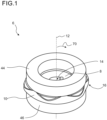
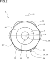
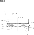
- Figs. 1 to 6 show a first embodiment of a damper inlay 6.
- the damper inlay 6 is a hybrid top mount inlay 6 for a vehicle.
- the damper inlay 6 comprises a core element 8.
- the damper inlay 6 moreover comprises a radial damper 10.
- the radial damper 10 is configured for damping radial loads perpendicular to a longitudinal axis 12 of the damper inlay 6.
- the radial damper 10 radially surrounds the core element 8.
- the core element 8 and the radial damper 10 comprise a centrally arranged through hole 14. The through hole extends along a longitudinal axis 12 of the damper inlay 6.
- the core element 8 and the radial damper 10 comprise a variable radial thickness 16 in a circumferential direction 18 around the longitudinal axis 12.
- the variable radial thickness 16 is incorporated by sections of higher radial thickness 20 that alternate with sections of lower radial thickness 22 in the circumferential direction 18. Between the sections of higher radial thickness 20 and lower radial thickness 22, thickness transition sections 24 are arranged.
- the thickness transition sections 24 provide a bent-free and steady thickness transition 26, 28, so that that no abrupt changes in thickness take place at the thickness transition sections 26, 28.
- the sections of higher radial thickness 20 comprise a convex outer contour 30.
- the sections of lower radial thickness 22 comprise a concave outer contour 32.
- the sections of the core element 8 having a higher radial thickness 20 correspond to sections of the radial damper 10 having a lower radial thickness.
- the sections of the core element 8 having a lower radial thickness 22 correspond to sections of the radial damper 10 having a higher radial thickness 20.
- An axial thickness 34 of the sections of higher radial thickness tapers with increasing radial distance 70 from the longitudinal axis 12.
- the radial damper 10 is mouldered around the core element 8. Furthermore, the radial damper 10 is preferably made of compact polyurethane, in particular thermoplastic polyurethane (TPU), or rubber.
- the centrally arranged through hole 14 comprises a groove 36 extending along the axial direction 38.
- the radial damper 10 comprises a first axial end face 40 and a second axial end face 42.
- the second axial end face 42 is opposite from the first axial end face 40.
- the damper inlay 6 furthermore comprises a first and second axial damping element 44, 46 for damping axial loads.
- the first axial damping element 44 is in contact with the first axial end face 40.
- the second axial damping element 46 is in contact with the second axial end face 42.
- the radial damper 10 encloses a core element 8 axially and radially at least partially.
- the core element 8 comprises a first axial height 48.
- the radial damper 10 comprises a second axial height 50.
- the second axial height 50 exceeds the first actual height 48.
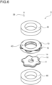
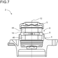
- Figs. 7 and 8 show a damper unit 2.
- the damper unit 2 comprises a damper housing 4 for accommodating a damper inlay 6.
- the damper unit 2 moreover comprises at least one damper inlay 6 inserted into said housing 4.
- figs. 1 to 6 reference is made to figs. 1 to 6 .
- fig. 7 the damper unit 2 is shown in a non-compressed state, wherein in fig. 8 , the damper unit 2 is shown in a compressed state.
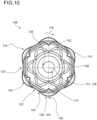
- Fig. 9 to 13 show an alternative embodiment of a damper inlay 106.
- the damper inlay 106 comprises a core element 108.
- the damper inlay 106 moreover comprises a radial damper 110.
- the radial damper 110 is configured for damping radial loads perpendicular to a longitudinal axis 112 of the damper inlay 106.
- the radial damper 110 radially surrounds the core element 108.
- the core element 108 and the radial damper 110 comprise a centrally arranged through hole 114.
- the through hole extends along the longitudinal axis 112 of the damper inlay 106.
- the core element 108 and the radial damper 110 comprise a radial thickness 116 in a circumferential direction 118 around the longitudinal axis 112.
- the variable radial thickness 116 comprises sections of higher radial thickness 120 that alternate with sections of lower radial thickness 122 in the circumferential direction.
- the damper inlay 106 moreover comprises thickness transition sections 124 that are arranged between the sections of higher radial thickness 120 and lower radial thickness 122.
- the thickness transition sections 124 provide a bent-free and steady thickness transition 126, 128.
- the sections of higher radial thickness 120 comprise a convex outer contour 130.
- the sections of lower radial thickness 122 comprise a concave outer contour 132.
- the sections of the core element 108 having a higher radial thickness 120 correspond to sections of the radial damper 110 having a lower radial thickness 122.
- the sections of the core element 108 having a lower radial thickness 122 correspond to sections of the radial damper 110 having a higher radial thickness 120.
- An axial thickness 134 of the sections of higher radial thickness 120 tappers with increasing radial distance 170 from the longitudinal axis 112.
- the radial damper 110 is moulded around the core element 108.
- the radial damper 110 is made of compact polyurethane, in particular of two-component polyurethane and/or thermo-plastic polyurethane (TPU).
- the centrally arranged through hole 114 comprises a groove 136 extending along the axial direction 138.
- the radial damper 110 comprises a first axial end face 140 and a second axial end face 142.
- the second axial end face 142 is opposite from the first end face 140.
- the radial damper 110 comprises a plurality of axial protrusions 152 extending from the first end face 140 and/or the second end face 142.
- the protrusions 152 are arranged on a radius coaxial to the longitudinal axis 154.
- the protrusions 152 are uniformly distributed over the radius.
- the protrusions 152 form a wavy ridge in the circumferential direction 118 around the longitudinal axis 112.
- the protrusions 152 extend axially starting from a base 158 being adjacent to the core 108 towards a tip 160 being remote from the core 108.
- the protrusions 152 taper from base 158 to tip 160.
- the core element 108 comprises a first section 162 radially surrounding the through hole 114.
- the core element 108 furthermore comprises a second section 164 radially surrounding the first section 162.
- the first section 162 comprises a constant axial thickness 166 and the second section 164 comprises a decreasing actual thickness 168. The thickness decreases with increasing radial distance 170 from the longitudinal axis 112.
- Figs. 14 and 15 show a damper unit 102.
- the damper unit 102 comprises the damper inlay 106 and a damper housing 104 for accommodating said damper inlay 106.
- the damper housing 104 moreover comprises a damper couple 105.
- the damper unit 102 is shown in a non-compressed state, wherein in fig. 15 , the damper unit 102 is shown in a compressed state.
Abstract
Description
- The invention relates to a damper inlay, in particular a hybrid top mount inlay for a vehicle, said damper inlay comprising a core element and a radial damper for damping radial loads perpendicular to a longitudinal axis of the damper inlay, said radial damper radially surrounding the core element, wherein the core element and radial damper comprise a centrally arranged through hole, the through hole extending along the longitudinal axis of the damper inlay.
- Damper inlays of the aforementioned kind are commonly used in the commercial vehicle industry, where they act so as to allow the vibrations of respective swing masses to decay quickly and are potentially classified as safety-relevant products. In vehicles, the tire-wheel suspension determines the character of the vehicle in terms of driving dynamics and comfort through its suspension and damping tuning. Depending on the geometric design of the vehicle axle, damper units are connected to the wheel suspension, for example either at the upper end or at both ends, via an elastic mounting, wherein hybrid damper inlays comprising plastic and metal components are being used as damping elements.
- To insert such damper inlays into their respective housing, damper inlays irregularly comprise an outer sleeve for achieving better mounting characteristics. While utilizing sleeves has been found to be beneficial for many applications, said sleeves increase the overall dimensions of the damper inlay and add manufacturing complexity, which also increases overall production costs.
- As a consequence, it was an object of the invention to provide a damper inlay of the initially mentioned type which overcomes the aforementioned problems as much as possible. In particular, it was an object of the invention to provide an improved damper inlay that comprises less parts, is easier to manufacture and may be installed conveniently into the housing.
- The invention attains the aforementioned object by suggesting a damper inlay according to claim 1. According to the invention, at least one of the core element or the radial damper comprise a variable radial thickness in a circumferential direction around the longitudinal axis. With the help of said variable radial thickness, in particular at the radial damper, no outer sleeve is required to insert or press the damper inlay into a top mount housing. Due to the variable radial thickness, the surface of the radial damper is precompressed only in part when inserted into the housing. The variable radial thickness furthermore ensures a tight fit when assembled into the housing. Furthermore, by varying the geometry of the core element and/or the radial damper, the stiffness of the damper inlay can be adjusted.
- According to a preferred embodiment, sections of higher radial thickness alternate with sections of lower radial thickness in the circumferential direction. In this way, only the sections of higher radial thickness of the radial damper contact the respective housing and get precompressed when inserted into the housing. The sections of higher radial thickness ensure a tight fit in the housing. Furthermore, the sections of higher radial thickness provide an improved deformation capacity. The sections of higher radial thickness can flexibly deform radially and axially when large loads are applied to the damper inlay so that the damper inlay can move better within the housing. Preferably, the sections of higher radial thickness remain in contact with a constant portion of the housing while the inlay moves.
- According to a preferred embodiment, the damper inlay comprises thickness transition sections between the sections of higher radial thickness and lower radial thickness. In this way, radial waves are established at the radial damper and/or the core element. Said design provides benefits with regard to manufacturing and allows for conveniently inserting the damper inlay into the housing, wherein the damper inlay is safely kept in place at the housing.
- According to a preferred embodiment, the thickness transition sections provide a bent-free thickness transition. The term bent-free is to be understood that no abrupt changes in thickness take place at the thickness transition sections. Preferably, the thickness transition sections provide a steady thickness transition. With the help of this, loads within the outer contours of the core element are distributed uniformly, wherein installation properties of the damper inlay are improved.
- Preferably, the sections of higher radial thickness comprise a convex outer contour. Providing the sections of higher radial thickness with a convex outer contour facilitates a convenient installation of the damper inlay into the housing.
- Preferably, the sections of lower radial thickness comprise a concave outer contour. Again, said design facilitates a convenient mountability of the inlay into housing. According to yet another preferred embodiment, the core element and the radial damper comprise the variable radial thickness in the circumferential direction around the longitudinal axis, and wherein sections of the core element having a higher radial thickness correspond to sections of the radial damper having a lower radial thickness.
- With the help of this design, the damping material thickness is maximized for those sections of the radial damper that contact the damper housing. In other words, in this way, a higher degree of compression of the radial damper is available for said sections compared to, for example, a circular outer geometry of the core element.
- Preferably, the sections of the core element having a lower radial thickness correspond to sections of the radial damper having a higher radial thickness. In this way, in the sections of the core element having a lower radial thickness more deformability is created. In the sections of the core element having a higher radial thickness, the radial thickness of the damping material is correspondingly low so that a high surface pressure is avoided. Further, the stiffness of the damper inlay is increased for those sections that do not regularly get in touch with the housing since the radial height of the radial damper is reduced for these sections.
- According to yet another preferred embodiment, the axial thickness of the sections of higher radial thickness tapers with increasing radial distance from the longitudinal axis. In this way, the tips of the sections of higher radial thickness can flex more easily since also the axial thickness of the sections of higher radial thickness is reduced with increasing radial distance from the longitudinal axis. This additionally facilitates a convenient assembly of the damper inlay into the housing.
- According to yet another preferred embodiment, the radial damper is moulded around the core element. In this way, a separation of radial damper and core element is inhibited within radial damper and core element are easy to manufacture.
- According to yet another preferred embodiment, the radial damper is made of compact polyurethane, in particular thermoplastic polyurethane (TPU) or rubber. These materials have been found to be beneficial to damp the radial loads applied to the damper inlay during operation. The axial damping elements made from volume compressible microcellular polyurethane can be moulded or injection moulded (depending on the material) to the radial damper. Radial dampers made of rubber must be vulcanized separately. The polyurethane materials can also be produced separately and assembled subsequently.
- According to yet another preferred embodiment, the centrally arranged through hole comprises a groove extending along the axial direction. With the help of said groove, a rotation of the damper inlay, which may be unwanted for certain kinds of application, is inhibited.
- According to yet another preferred embodiment, said radial damper comprises a first axial end face and a second axial end face, the second axial end face being opposite from the first axial end face, and a first and second axial damping element for damping axial loads, the first axial damping element being in contact with the first axial end face and the second axial damping element being in contact with the second axial end face. The axial damping elements are configured for taking the main axial loads. Said axial damping elements mainly define the axial stiffness of the overall damper inlay.
- Preferably, the at least one first axial damping element or second axial damping element comprises or consists of microcellular polyurethane, in particular volume compressible microcellular polyurethane. A suitable material in this regard is for example Cellasto, a trademark of BASF. When inserted into the housing, the axial damping elements are pre-compressed. Therefore, they are always in contact with the housing and the core element.
- Microcellular polyurethane elastomers which, in a preferred embodiment, have a density according to DIN 53420 of 200 kg/m3 to 1100 kg/m3, preferably 300 kg/m3 to 800 kg/m3, a tensile strength according to DIN 53571 of 2 N/mm2, preferably 2 N/mm2 to 8 N/mm2, an elongation according to DIN 53571 of 300%, preferably 300% to 700%, and a tear strength according to DIN 53515 of preferably 8 N/mm to 25 N/mm are particularly preferred.
- The elastomers are preferably microcellular elastomers on the basis of polyisocyanate polyaddition products, preferably having cells with a diameter of 0.01 mm to 0.5 mm, particularly preferably 0.01 to 0.15 mm.
- Elastomers on the basis of polyisocyanate polyaddition products and the production thereof are known in general and described numerously, for example in
EP A 62 835 EP A 36 994EP A 250 969 DE A 195 48 770 andDE A 195 48 771 . - Production customarily takes place by reacting isocyanates with compounds which are reactive to isocyanates.
- The elastomers on the basis of cellular polyisocyanate polyaddition products are customarily produced in a mold in which the reactive starting components are reacted with one another. Suitable molds here are generally customary molds, for example metal molds, which, on the basis of their shape, ensure the three dimensional shape according to the invention
- The polyisocyanate polyaddition products can be produced according to generally known methods, for example by the following starting substances being used in a single or two stage process:
- (a) isocyanate,
- (b) compounds reactive to isocyanates,
- (c) water and optionally
- (d) catalysts,
- (e) blowing agents and/or
- (f) auxiliary and/or additional substances, for example polysiloxanes and/or fatty acid sulfonates.
- The surface temperature of the inner wall of the mold is customarily 40°C to 95°C, preferably 50°C to 90°C. The production of the molded parts is advantageously carried out at an NCO/OH ratio of 0.85 to 1.20, wherein the heated starting components are mixed and brought in a quantity corresponding to the desired molded part density into a heated, preferably tightly closing molding tool. The molded parts are cured for 5 minutes to 60 minutes and then can be removed from the mold. The quantity of the reaction mixture introduced into the molding tool is customarily dimensioned in such a manner that the molded bodies obtained have the density already presented. The starting components are customarily introduced into the molding tool at a temperature of 15°C to 120°C, preferably of 30°C to 110°C. The degrees of compression for producing the molded bodies lie between 1.1 and 8, preferably between 2 and 6. The cellular polyisocyanate polyaddition products are expediently produced according to the "one shot" method with the aid of high pressure technology, low pressure technology or in particular reaction injection molding technology (RIM) in open or preferably closed molding tools. The reaction is carried out in particular by compression in a closed molding tool. The reaction injection molding technology is described, for example, by H. Piechota and H. Röhr in "Integralschaumstoffe", Carl Hanser-Verlag, Munich, Vienna 1975; D.J. Prepelka and J.L. Wharton in Journal of Cellular Plastics, March/April 1975, pages 87 to 98 and U. Knipp in Journal of Cellular Plastics, March/April 1973, pages 76-84.
- Preferably, the radial damper encloses the core element axially and radially at least partially, wherein the core element comprises a first axial height and the radial damper comprises a second axial height, and wherein the second axial height exceeds the first axial height.
- According to yet another preferred embodiment, said radial damper comprises a first axial end face and a second axial end face, the second axial end face being opposite from the first end face and wherein said radial damper comprises a plurality of axial protrusions extending form the first end face and/or the second end face. These axial protrusions are utilized as an alternative to the axial damping elements to provide the axial damping functionality.
- Preferably, said protrusions are arranged on a radius coaxial to the longitudinal axis. In this way, the inlay can be conveniently inserted into the housing. According to a preferred embodiment, said protrusions are uniformly distributed over the radius. Preferably, said protrusions form a wavy ridge in the circumferential direction around the longitudinal axis. Said waves have been found to be beneficial to improve the compression properties of the damper inlay. By adjusting the number and geometry of the protrusions, the axial damping properties of the damper inlay may be influenced.
- According to yet another preferred embodiment, said protrusions extend axially starting from a base being adjacent to the core towards a tip being remote from the core, wherein the protrusions taper from base to tip. In this way, the axial damping properties of the damper inlay are improved.
- According to yet another preferred embodiment, the core element comprises a first section radially surrounding the through hole and a second section radially surrounding the first section, wherein the first section comprises a constant axial thickness and the second section comprises a decreasing axial thickness, wherein the thickness decreases with increasing radial distance from the longitudinal axis. This design of the core element in combination with the radial damper has been found to be beneficial to further improve the radial and axial damping properties of the damper inlay.
- According to a preferred embodiment, the core element is made of at least one of the following materials: steel, aluminium, resp. alloys, plurality segments of diff. materials, inter alia hard plastics e.g. gfrp (polyamide matrix) .
- For a more complete understanding of the invention, the invention will now be described in detail with reference to the accompanying drawings. The detailed description will illustrate and describe what is considered as a preferred embodiment of the invention. It should of course be understood that various modifications and changes in form or detail could readily be made without departing from the spirit of the invention. It is therefore intended that the invention may not be limited to the exact form and detail shown and described herein, nor to anything less than the whole of the invention disclosed herein and as claimed hereinafter. Further, the features described in the description, the drawings and the claims disclosing the invention may be essential for the invention considered alone or in combination. In particular, any reference signs in the claims shall not be construed as limiting the scope of the invention. The wording "comprising" does not exclude other elements or steps. The wording "a" or "an" does not exclude a plurality.
- This invention will now be described with reference to the accompanying drawings which illustrate, by way of example and not by way of limitation, one of several possible embodiments of damper inlays as proposed herein, and wherein:
-
Fig. 1 to 6 shows a first embodiment of a damper inlay according to the invention in different views; -
Fig. 7 and8 : show the damper inlay according tofigs. 1 to 6 inserted into a damper housing forming a damper unit; -
Fig. 9 to 13 : show an alternative embodiment of a damper inlay according to the invention in different views; -
Fig. 14 and15 : show the damper inlay according tofigs. 9 to 13 inserted into a damper housing forming a damper unit; -
Figs. 1 to 6 show a first embodiment of adamper inlay 6. Thedamper inlay 6 is a hybridtop mount inlay 6 for a vehicle. Thedamper inlay 6 comprises acore element 8. Thedamper inlay 6 moreover comprises aradial damper 10. Theradial damper 10 is configured for damping radial loads perpendicular to alongitudinal axis 12 of thedamper inlay 6. Theradial damper 10 radially surrounds thecore element 8. Thecore element 8 and theradial damper 10 comprise a centrally arranged throughhole 14. The through hole extends along alongitudinal axis 12 of thedamper inlay 6. Thecore element 8 and theradial damper 10 comprise avariable radial thickness 16 in acircumferential direction 18 around thelongitudinal axis 12. Thevariable radial thickness 16 is incorporated by sections ofhigher radial thickness 20 that alternate with sections oflower radial thickness 22 in thecircumferential direction 18. Between the sections ofhigher radial thickness 20 andlower radial thickness 22,thickness transition sections 24 are arranged. Thethickness transition sections 24 provide a bent-free and steady thickness transition 26, 28, so that that no abrupt changes in thickness take place at the thickness transition sections 26, 28. - The sections of
higher radial thickness 20 comprise a convexouter contour 30. The sections oflower radial thickness 22 comprise a concaveouter contour 32. The sections of thecore element 8 having ahigher radial thickness 20 correspond to sections of theradial damper 10 having a lower radial thickness. The sections of thecore element 8 having alower radial thickness 22 correspond to sections of theradial damper 10 having ahigher radial thickness 20. Anaxial thickness 34 of the sections of higher radial thickness tapers with increasingradial distance 70 from thelongitudinal axis 12. - The
radial damper 10 is mouldered around thecore element 8. Furthermore, theradial damper 10 is preferably made of compact polyurethane, in particular thermoplastic polyurethane (TPU), or rubber. The centrally arranged throughhole 14 comprises agroove 36 extending along theaxial direction 38. Theradial damper 10 comprises a firstaxial end face 40 and a secondaxial end face 42. The secondaxial end face 42 is opposite from the firstaxial end face 40. Thedamper inlay 6 furthermore comprises a first and second axial dampingelement element 44 is in contact with the firstaxial end face 40. The second axial dampingelement 46 is in contact with the secondaxial end face 42. Furthermore, theradial damper 10 encloses acore element 8 axially and radially at least partially. Thecore element 8 comprises a firstaxial height 48. Theradial damper 10 comprises a secondaxial height 50. The secondaxial height 50 exceeds the firstactual height 48. -
Figs. 7 and8 show adamper unit 2. Thedamper unit 2 comprises adamper housing 4 for accommodating adamper inlay 6. Thedamper unit 2 moreover comprises at least onedamper inlay 6 inserted into saidhousing 4. With regard to details regarding thedamper inlay 6, reference is made tofigs. 1 to 6 . Infig. 7 , thedamper unit 2 is shown in a non-compressed state, wherein infig. 8 , thedamper unit 2 is shown in a compressed state. -
Fig. 9 to 13 show an alternative embodiment of adamper inlay 106. Thedamper inlay 106 comprises acore element 108. Thedamper inlay 106 moreover comprises aradial damper 110. Theradial damper 110 is configured for damping radial loads perpendicular to alongitudinal axis 112 of thedamper inlay 106. Theradial damper 110 radially surrounds thecore element 108. Thecore element 108 and theradial damper 110 comprise a centrally arranged throughhole 114. The through hole extends along thelongitudinal axis 112 of thedamper inlay 106. Thecore element 108 and theradial damper 110 comprise aradial thickness 116 in acircumferential direction 118 around thelongitudinal axis 112. - The
variable radial thickness 116 comprises sections of higherradial thickness 120 that alternate with sections of lowerradial thickness 122 in the circumferential direction. Thedamper inlay 106 moreover comprisesthickness transition sections 124 that are arranged between the sections of higherradial thickness 120 andlower radial thickness 122. Thethickness transition sections 124 provide a bent-free and steady thickness transition 126, 128. The sections of higherradial thickness 120 comprise a convexouter contour 130. The sections of lowerradial thickness 122 comprise a concaveouter contour 132. - The sections of the
core element 108 having ahigher radial thickness 120 correspond to sections of theradial damper 110 having alower radial thickness 122. The sections of thecore element 108 having alower radial thickness 122 correspond to sections of theradial damper 110 having ahigher radial thickness 120. Anaxial thickness 134 of the sections of higherradial thickness 120 tappers with increasing radial distance 170 from thelongitudinal axis 112. Theradial damper 110 is moulded around thecore element 108. Theradial damper 110 is made of compact polyurethane, in particular of two-component polyurethane and/or thermo-plastic polyurethane (TPU). Furthermore, the centrally arranged throughhole 114 comprises agroove 136 extending along theaxial direction 138. Theradial damper 110 comprises a firstaxial end face 140 and a secondaxial end face 142. The secondaxial end face 142 is opposite from thefirst end face 140. - The
radial damper 110 comprises a plurality ofaxial protrusions 152 extending from thefirst end face 140 and/or thesecond end face 142. Theprotrusions 152 are arranged on a radius coaxial to the longitudinal axis 154. Theprotrusions 152 are uniformly distributed over the radius. Theprotrusions 152 form a wavy ridge in thecircumferential direction 118 around thelongitudinal axis 112. Theprotrusions 152 extend axially starting from a base 158 being adjacent to thecore 108 towards atip 160 being remote from thecore 108. Theprotrusions 152 taper frombase 158 to tip 160. Thecore element 108 comprises a first section 162 radially surrounding the throughhole 114. Thecore element 108 furthermore comprises a second section 164 radially surrounding the first section 162. The first section 162 comprises a constantaxial thickness 166 and the second section 164 comprises a decreasing actual thickness 168. The thickness decreases with increasing radial distance 170 from thelongitudinal axis 112. -
Figs. 14 and15 show adamper unit 102. Thedamper unit 102 comprises thedamper inlay 106 and adamper housing 104 for accommodating saiddamper inlay 106. Thedamper housing 104 moreover comprises adamper couple 105. Infig. 14 , thedamper unit 102 is shown in a non-compressed state, wherein infig. 15 , thedamper unit 102 is shown in a compressed state. -
- 2
- damper unit
- 4
- damper housing
- 5
- damper cover
- 6
- damper inlay
- 8
- core element
- 10
- radial damper
- 12
- longitudinal axis
- 14
- centrally arranged through hole
- 16
- variable radial thickness
- 18
- circumferential direction
- 20
- sections of higher radial thickness
- 22
- sections of lower radial thickness
- 24
- thickness transition section
- 26
- bend-free thickness transition
- 28
- steady thickness transition
- 30
- convex outer contour
- 32
- concave outer contour
- 34
- tapering axial thicknesses
- 36
- groove
- 38
- axial direction
- 40
- first axial end face
- 42
- second axial end face
- 44
- first axial damping element
- 46
- second axial damping element
- 48
- first axial height of core element
- 50
- second axial height of radial damper
- 70
- radial distance
- 102
- damper unit
- 104
- damper housing
- 105
- damper cover
- 106
- damper inlay
- 108
- core element
- 110
- radial damper
- 112
- longitudinal axis
- 114
- centrally arranged through hole
- 116
- variable radial thickness
- 118
- circumferential direction
- 120
- sections of higher radial thickness
- 122
- sections of lower radial thickness
- 124
- thickness transition section
- 126
- bend-free thickness transition
- 128
- steady thickness transition
- 130
- convex outer contour
- 132
- concave outer contour
- 134
- tapering axial thicknesses
- 136
- groove
- 138
- axial direction
- 140
- first axial end face
- 142
- second axial end face
- 152
- axial protrusions
- 156
- wavy ridge
- 158
- base
- 160
- tip
- 162
- first section of core element
- 164
- second section of core element
- 166
- axial thickness
- 170
- radial distance
Claims (15)
- A damper inlay (6, 106), in particular a hybrid top mount inlay (6, 106) for a vehicle, in particular a commercial vehicle, said damper inlay (6, 106) comprising:a core element (8, 108),a radial damper (10, 110) for damping radial loads perpendicular to a longitudinal axis (12, 112) of the damper inlay (6, 106), said radial damper (10, 110) radially surrounding the core element (8, 108),wherein the core element (8, 108) and the radial damper (10, 110) comprise a centrally arranged through hole (14, 114), the through hole extending along the longitudinal axis (12, 112) of the damper inlay (6, 106),characterized in that at least one of the core element (8, 108) or the radial damper (10, 110) comprise a variable radial thickness (16, 116) in a circumferential direction (18, 118) around the longitudinal axis (12, 112).
- The damper inlay (6, 106) according to claim 1,
wherein sections of higher radial thickness (20, 120) alternate with sections of lower radial thickness (22, 122) in the circumferential direction (18, 118). - The damper inlay (6, 106) according to claim 2,
comprising thickness transition sections (24, 124) between the sections of higher radial thickness (20, 120) and lower radial thickness (22, 122). - The damper inlay (6 ,106) according to claim 3,
wherein the thickness transition sections (24, 124) provide a bend-free thickness transition (26, 126). - The damper inlay (6, 106) according to any of the preceding claims,
wherein the sections of higher radial thickness (20, 120) comprise a convex outer contour (30, 130) and/or wherein the sections of lower radial thickness (22, 122) comprise a concave outer contour (32, 132). - The damper inlay (6, 106) according to according to any of the preceding claims,wherein the core element (8, 108) and the radial damper (10, 110) comprise the variable radial thickness (16, 116) in the circumferential direction (18, 118) around the longitudinal axis (12, 112),and wherein sections of the core element (8, 108) having a higher radial thickness (20, 120) correspond to sections of the radial damper (10, 110) having a lower radial thickness (22, 122), in particular wherein sections of the core element (8, 108) having a lower radial thickness correspond (22, 122) to sections of the radial damper (10, 110) having a higher radial thickness (20, 120).
- The damper inlay (6, 106) according to any of the preceding claims,
wherein an axial thicknesses (34, 134) of the sections of higher radial thickness (20, 120) tapers with increasing radial distance (70, 170) from the longitudinal axis (12, 112). - The damper inlay (6, 106) according to any of the preceding claims,
characterized in that the radial damper (10, 110) is made of polyurethane, in particular thermoplastic polyurethane (TPU), or rubber. - The damper inlay (6) according to any of the preceding claims,wherein said radial damper (10) comprises a first axial end face (40) and a second axial end face (42), the second axial end face (42) being opposite from the first end face (40) anda first and a second axial damping element (44, 46) for damping axial loads, the first axial damping element (44) being in contact with the first axial end face (40) and the second axial damping element (46) being in contact with the second axial end face (42).
- The damper inlay (6) according to claim 9,
characterized in that at least one of the first axial damping element (44) and the second axial damping element (46) comprises or consists of microcellular polyurethane, in particular volume compressible microcellular polyurethane. - The damper inlay (6) according to any of the preceding claims,
wherein the radial damper (10) encloses the core element (8) axially and radially at least partially, and wherein the core element (8) comprises a first axial height (48) and the radial damper (10) comprises a second axial height (50) and wherein the second axial height (50) exceeds the first axial height (48). - The damper inlay (106) according to one of claims 1 - 8,wherein said radial damper (110) comprises a first axial end face (140) and a second axial end face (142), the second axial end face (142) being opposite from the first end face (140) andwherein said radial damper (110) comprises a plurality of axial protrusions (152) extending from the first end face (140) and/or the second end face (142).
- The damper inlay (106) according to claim 12,
wherein said protrusions (152) are arranged on a radius coaxial to the longitudinal axis (154) and/or wherein said protrusions (152) are uniformly distributed over the radius and/or form a wavy ridge (156) in the circumferential direction (118) around the longitudinal axis (112). - The damper inlay (106) according to one of claims 12 or 13,
wherein the core element (108) comprises a first section (162) radially surrounding the through hole (114) and a second section (164) radially surrounding the first section (162), wherein the first section (162) comprises a constant axial thickness (166) and the second section (164) comprises a decreasing axial thickness (168), wherein the thickness decreases with increasing radial distance (170) from the longitudinal axis (112). - A damper unit (2, 102) for a vehicle, comprisinga damper housing (4, 104) for accommodating a damper inlay (6, 106), andat least one damper inlay (6, 106),characterized in that the damper inlay (6, 106) is designed according to at least one of the previous claims.
Priority Applications (1)
| Application Number | Priority Date | Filing Date | Title |
|---|---|---|---|
| EP21204048.9A EP4170194A1 (en) | 2021-10-21 | 2021-10-21 | Damper inlay for a vehicle and a vehicle comprising said damper inlay |
Applications Claiming Priority (1)
| Application Number | Priority Date | Filing Date | Title |
|---|---|---|---|
| EP21204048.9A EP4170194A1 (en) | 2021-10-21 | 2021-10-21 | Damper inlay for a vehicle and a vehicle comprising said damper inlay |
Publications (1)
| Publication Number | Publication Date |
|---|---|
| EP4170194A1 true EP4170194A1 (en) | 2023-04-26 |
Family
ID=78371879
Family Applications (1)
| Application Number | Title | Priority Date | Filing Date |
|---|---|---|---|
| EP21204048.9A Pending EP4170194A1 (en) | 2021-10-21 | 2021-10-21 | Damper inlay for a vehicle and a vehicle comprising said damper inlay |
Country Status (1)
| Country | Link |
|---|---|
| EP (1) | EP4170194A1 (en) |
Citations (16)
| Publication number | Priority date | Publication date | Assignee | Title |
|---|---|---|---|---|
| EP0036994A2 (en) | 1980-03-28 | 1981-10-07 | Bayer Ag | Process for preparing waterproof articles from cellular polyurethane elastomers and their use as spring elements |
| EP0062835A1 (en) | 1981-04-04 | 1982-10-20 | Elastogran GmbH | Process for the preparation of closed-cell polyurethane moulded articles having a compact outer layer |
| EP0250969A1 (en) | 1986-06-24 | 1988-01-07 | Bayer Ag | Process for the preparation of cellular polyurethane elastomers |
| JPH07233844A (en) * | 1994-02-22 | 1995-09-05 | Bridgestone Corp | Strut mount |
| DE19536049A1 (en) * | 1995-09-28 | 1997-04-03 | Porsche Ag | Unvulcanised elastic bearing for wheel suspension |
| DE19548771A1 (en) | 1995-12-23 | 1997-06-26 | Basf Ag | Microcellular polyurethane elastomer containing urea groups |
| DE19548770A1 (en) | 1995-12-23 | 1997-06-26 | Basf Ag | Microcellular polyurethane elastomer containing urea groups |
| FR2812242A1 (en) * | 2000-07-27 | 2002-02-01 | C F Gomma Barre Thomas | Automobile deformable axle comprises pair of longitudinal suspension arms connected by torsion deformable crosspiece, one end of each arm connected to bodywork by elastic articulation and one end to wheel hub |
| US20030175073A1 (en) * | 2002-03-13 | 2003-09-18 | Ford Global Technologies, Inc. | Stabilizer bar system for automotive vehicle |
| US20040017035A1 (en) * | 2002-06-29 | 2004-01-29 | Christian Treder | Damper support having a contoured end face for a shock absorber of a motor vehicle |
| FR2898170A1 (en) * | 2006-03-06 | 2007-09-07 | C F Gomma Barre Thomas Sa | Suspension support for strengthening a connection and filtering between body shell and the suspension of a vehicle, comprises a main framework and a secondary framework forming lid that surrounds an interior space of the frameworks |
| JP2011169416A (en) * | 2010-02-19 | 2011-09-01 | Toyo Tire & Rubber Co Ltd | Suspension support |
| DE102012012902A1 (en) * | 2011-07-11 | 2013-01-17 | Contitech Vibration Control Gmbh | Leveling Module |
| US20130187320A1 (en) * | 2012-01-25 | 2013-07-25 | Basf Se | Shock absorption mount having a housing with a contoured inner surface |
| US20160185173A1 (en) * | 2014-11-13 | 2016-06-30 | Mahindra Vehicle Manufactures Limited | Shock Absorber Upper Mount |
| CN109695650A (en) * | 2019-02-22 | 2019-04-30 | 上海凯众材料科技股份有限公司 | The multiple combined-type inner core supported on automobile absorber |
-
2021
- 2021-10-21 EP EP21204048.9A patent/EP4170194A1/en active Pending
Patent Citations (16)
| Publication number | Priority date | Publication date | Assignee | Title |
|---|---|---|---|---|
| EP0036994A2 (en) | 1980-03-28 | 1981-10-07 | Bayer Ag | Process for preparing waterproof articles from cellular polyurethane elastomers and their use as spring elements |
| EP0062835A1 (en) | 1981-04-04 | 1982-10-20 | Elastogran GmbH | Process for the preparation of closed-cell polyurethane moulded articles having a compact outer layer |
| EP0250969A1 (en) | 1986-06-24 | 1988-01-07 | Bayer Ag | Process for the preparation of cellular polyurethane elastomers |
| JPH07233844A (en) * | 1994-02-22 | 1995-09-05 | Bridgestone Corp | Strut mount |
| DE19536049A1 (en) * | 1995-09-28 | 1997-04-03 | Porsche Ag | Unvulcanised elastic bearing for wheel suspension |
| DE19548771A1 (en) | 1995-12-23 | 1997-06-26 | Basf Ag | Microcellular polyurethane elastomer containing urea groups |
| DE19548770A1 (en) | 1995-12-23 | 1997-06-26 | Basf Ag | Microcellular polyurethane elastomer containing urea groups |
| FR2812242A1 (en) * | 2000-07-27 | 2002-02-01 | C F Gomma Barre Thomas | Automobile deformable axle comprises pair of longitudinal suspension arms connected by torsion deformable crosspiece, one end of each arm connected to bodywork by elastic articulation and one end to wheel hub |
| US20030175073A1 (en) * | 2002-03-13 | 2003-09-18 | Ford Global Technologies, Inc. | Stabilizer bar system for automotive vehicle |
| US20040017035A1 (en) * | 2002-06-29 | 2004-01-29 | Christian Treder | Damper support having a contoured end face for a shock absorber of a motor vehicle |
| FR2898170A1 (en) * | 2006-03-06 | 2007-09-07 | C F Gomma Barre Thomas Sa | Suspension support for strengthening a connection and filtering between body shell and the suspension of a vehicle, comprises a main framework and a secondary framework forming lid that surrounds an interior space of the frameworks |
| JP2011169416A (en) * | 2010-02-19 | 2011-09-01 | Toyo Tire & Rubber Co Ltd | Suspension support |
| DE102012012902A1 (en) * | 2011-07-11 | 2013-01-17 | Contitech Vibration Control Gmbh | Leveling Module |
| US20130187320A1 (en) * | 2012-01-25 | 2013-07-25 | Basf Se | Shock absorption mount having a housing with a contoured inner surface |
| US20160185173A1 (en) * | 2014-11-13 | 2016-06-30 | Mahindra Vehicle Manufactures Limited | Shock Absorber Upper Mount |
| CN109695650A (en) * | 2019-02-22 | 2019-04-30 | 上海凯众材料科技股份有限公司 | The multiple combined-type inner core supported on automobile absorber |
Non-Patent Citations (3)
| Title |
|---|
| D.J. PREPELKAJ.L. WHARTON, JOURNAL OF CELLULAR PLASTICS, March 1975 (1975-03-01), pages 87 - 98 |
| H. PIECHOTAH. ROHR: "Integralschaumstoffe", 1975, CARL HANSER-VERLAG |
| U. KNIPP, JOURNAL OF CELLULAR PLASTICS, March 1973 (1973-03-01), pages 76 - 84 |
Similar Documents
| Publication | Publication Date | Title |
|---|---|---|
| EP0974024B1 (en) | Composite elastomeric spring | |
| EP1832780B1 (en) | Radially flexible bushing | |
| CN109154347B (en) | Spring element for a vehicle shock absorber, vehicle shock absorber and vehicle having a vehicle shock absorber | |
| WO2008058914A1 (en) | Round bearing | |
| EP4170194A1 (en) | Damper inlay for a vehicle and a vehicle comprising said damper inlay | |
| EP3969778B1 (en) | Spring element, in particular jounce bumper, for a vehicle shock absorber | |
| EP3969779B1 (en) | Spring element, in particular jounce bumper, for a vehicle shock absorber | |
| EP2561246B1 (en) | Damper bearing with tapering end faces and method for production thereof | |
| EP4107408B1 (en) | Jounce bumper assembly and suspension system | |
| EP4230429A1 (en) | A damper inlay for a vehicle and a vehicle comprising said damper inlay | |
| EP3976989B1 (en) | Spring element, in particular jounce bumper, for a vehicle suspension | |
| US20230167869A1 (en) | Support ring for a jounce bumper of a suspension system, jounce bumper assembly and use thereof | |
| EP3976988B1 (en) | Spring element, in particular jounce bumper, for a vehicle suspension | |
| US11959526B2 (en) | Spring element, in particular jounce bumper, for a vehicle suspension | |
| CN109073032A (en) | Spring element for vehicle shock absorber and vehicle shock absorber and vehicle with spring element | |
| US20190301556A1 (en) | Method for manufacturing vibration isolation apparatus | |
| EP4025803A1 (en) | Damper mount for a vehicle | |
| EP3812183A2 (en) | Suspension component of an automotive vehicle | |
| EP4069992A1 (en) | Jounce bumper of an automotive vehicle suspension system, and method of producing such a jounce bumper |
Legal Events
| Date | Code | Title | Description |
|---|---|---|---|
| PUAI | Public reference made under article 153(3) epc to a published international application that has entered the european phase |
Free format text: ORIGINAL CODE: 0009012 |
|
| STAA | Information on the status of an ep patent application or granted ep patent |
Free format text: STATUS: THE APPLICATION HAS BEEN PUBLISHED |
|
| AK | Designated contracting states |
Kind code of ref document: A1 Designated state(s): AL AT BE BG CH CY CZ DE DK EE ES FI FR GB GR HR HU IE IS IT LI LT LU LV MC MK MT NL NO PL PT RO RS SE SI SK SM TR |
|
| STAA | Information on the status of an ep patent application or granted ep patent |
Free format text: STATUS: REQUEST FOR EXAMINATION WAS MADE |
|
| 17P | Request for examination filed |
Effective date: 20231026 |
|
| RBV | Designated contracting states (corrected) |
Designated state(s): AL AT BE BG CH CY CZ DE DK EE ES FI FR GB GR HR HU IE IS IT LI LT LU LV MC MK MT NL NO PL PT RO RS SE SI SK SM TR |