EP3976989B1 - Spring element, in particular jounce bumper, for a vehicle suspension - Google Patents
Spring element, in particular jounce bumper, for a vehicle suspension Download PDFInfo
- Publication number
- EP3976989B1 EP3976989B1 EP20730265.4A EP20730265A EP3976989B1 EP 3976989 B1 EP3976989 B1 EP 3976989B1 EP 20730265 A EP20730265 A EP 20730265A EP 3976989 B1 EP3976989 B1 EP 3976989B1
- Authority
- EP
- European Patent Office
- Prior art keywords
- spring element
- retention elements
- base body
- retention
- mounting cap
- Prior art date
- Legal status (The legal status is an assumption and is not a legal conclusion. Google has not performed a legal analysis and makes no representation as to the accuracy of the status listed.)
- Active
Links
- 239000000725 suspension Substances 0.000 title claims description 12
- 230000014759 maintenance of location Effects 0.000 claims description 110
- 230000007704 transition Effects 0.000 claims description 14
- 230000002093 peripheral effect Effects 0.000 claims description 13
- 230000013011 mating Effects 0.000 claims description 12
- 229920001971 elastomer Polymers 0.000 claims description 8
- 239000000806 elastomer Substances 0.000 claims description 8
- 229920001228 polyisocyanate Polymers 0.000 claims description 8
- 239000005056 polyisocyanate Substances 0.000 claims description 8
- 230000001413 cellular effect Effects 0.000 claims description 6
- 230000006835 compression Effects 0.000 description 7
- 238000007906 compression Methods 0.000 description 7
- 238000009434 installation Methods 0.000 description 7
- 238000000465 moulding Methods 0.000 description 5
- 238000005516 engineering process Methods 0.000 description 4
- 239000012948 isocyanate Substances 0.000 description 4
- 150000002513 isocyanates Chemical class 0.000 description 4
- 238000004519 manufacturing process Methods 0.000 description 3
- 239000002184 metal Substances 0.000 description 3
- 238000000034 method Methods 0.000 description 3
- -1 polysiloxanes Polymers 0.000 description 3
- IJGRMHOSHXDMSA-UHFFFAOYSA-N Atomic nitrogen Chemical compound N#N IJGRMHOSHXDMSA-UHFFFAOYSA-N 0.000 description 2
- 229930040373 Paraformaldehyde Natural products 0.000 description 2
- 230000009286 beneficial effect Effects 0.000 description 2
- 150000001875 compounds Chemical class 0.000 description 2
- 238000013016 damping Methods 0.000 description 2
- 230000000694 effects Effects 0.000 description 2
- 239000004033 plastic Substances 0.000 description 2
- 229920003023 plastic Polymers 0.000 description 2
- 229920006324 polyoxymethylene Polymers 0.000 description 2
- 229920003225 polyurethane elastomer Polymers 0.000 description 2
- 230000000750 progressive effect Effects 0.000 description 2
- 238000010107 reaction injection moulding Methods 0.000 description 2
- 125000006850 spacer group Chemical group 0.000 description 2
- 239000000126 substance Substances 0.000 description 2
- 239000004604 Blowing Agent Substances 0.000 description 1
- 229920002396 Polyurea Polymers 0.000 description 1
- 239000004433 Thermoplastic polyurethane Substances 0.000 description 1
- 239000000853 adhesive Substances 0.000 description 1
- 230000001070 adhesive effect Effects 0.000 description 1
- 230000015572 biosynthetic process Effects 0.000 description 1
- 238000005266 casting Methods 0.000 description 1
- 239000003054 catalyst Substances 0.000 description 1
- 235000014113 dietary fatty acids Nutrition 0.000 description 1
- 229930195729 fatty acid Natural products 0.000 description 1
- 239000000194 fatty acid Substances 0.000 description 1
- 239000007789 gas Substances 0.000 description 1
- 230000000977 initiatory effect Effects 0.000 description 1
- 238000003780 insertion Methods 0.000 description 1
- 230000037431 insertion Effects 0.000 description 1
- 238000002955 isolation Methods 0.000 description 1
- 239000007788 liquid Substances 0.000 description 1
- 239000000463 material Substances 0.000 description 1
- 239000000203 mixture Substances 0.000 description 1
- 229910052757 nitrogen Inorganic materials 0.000 description 1
- 229920000642 polymer Polymers 0.000 description 1
- 229920001296 polysiloxane Polymers 0.000 description 1
- 239000011541 reaction mixture Substances 0.000 description 1
- 230000002787 reinforcement Effects 0.000 description 1
- 239000012858 resilient material Substances 0.000 description 1
- 238000005096 rolling process Methods 0.000 description 1
- 238000000926 separation method Methods 0.000 description 1
- 239000012815 thermoplastic material Substances 0.000 description 1
- 229920002803 thermoplastic polyurethane Polymers 0.000 description 1
- XLYOFNOQVPJJNP-UHFFFAOYSA-N water Substances O XLYOFNOQVPJJNP-UHFFFAOYSA-N 0.000 description 1
Images

Classifications
-
- B—PERFORMING OPERATIONS; TRANSPORTING
- B60—VEHICLES IN GENERAL
- B60G—VEHICLE SUSPENSION ARRANGEMENTS
- B60G11/00—Resilient suspensions characterised by arrangement, location or kind of springs
- B60G11/22—Resilient suspensions characterised by arrangement, location or kind of springs having rubber springs only
- B60G11/24—Resilient suspensions characterised by arrangement, location or kind of springs having rubber springs only characterised by means specially adapted for attaching the spring to axle or sprung part of the vehicle
-
- F—MECHANICAL ENGINEERING; LIGHTING; HEATING; WEAPONS; BLASTING
- F16—ENGINEERING ELEMENTS AND UNITS; GENERAL MEASURES FOR PRODUCING AND MAINTAINING EFFECTIVE FUNCTIONING OF MACHINES OR INSTALLATIONS; THERMAL INSULATION IN GENERAL
- F16F—SPRINGS; SHOCK-ABSORBERS; MEANS FOR DAMPING VIBRATION
- F16F1/00—Springs
- F16F1/36—Springs made of rubber or other material having high internal friction, e.g. thermoplastic elastomers
- F16F1/373—Springs made of rubber or other material having high internal friction, e.g. thermoplastic elastomers characterised by having a particular shape
- F16F1/3732—Springs made of rubber or other material having high internal friction, e.g. thermoplastic elastomers characterised by having a particular shape having an annular or the like shape, e.g. grommet-type resilient mountings
-
- B—PERFORMING OPERATIONS; TRANSPORTING
- B60—VEHICLES IN GENERAL
- B60G—VEHICLE SUSPENSION ARRANGEMENTS
- B60G7/00—Pivoted suspension arms; Accessories thereof
- B60G7/04—Buffer means for limiting movement of arms
-
- F—MECHANICAL ENGINEERING; LIGHTING; HEATING; WEAPONS; BLASTING
- F16—ENGINEERING ELEMENTS AND UNITS; GENERAL MEASURES FOR PRODUCING AND MAINTAINING EFFECTIVE FUNCTIONING OF MACHINES OR INSTALLATIONS; THERMAL INSULATION IN GENERAL
- F16F—SPRINGS; SHOCK-ABSORBERS; MEANS FOR DAMPING VIBRATION
- F16F9/00—Springs, vibration-dampers, shock-absorbers, or similarly-constructed movement-dampers using a fluid or the equivalent as damping medium
- F16F9/32—Details
- F16F9/58—Stroke limiting stops, e.g. arranged on the piston rod outside the cylinder
-
- B—PERFORMING OPERATIONS; TRANSPORTING
- B60—VEHICLES IN GENERAL
- B60G—VEHICLE SUSPENSION ARRANGEMENTS
- B60G2202/00—Indexing codes relating to the type of spring, damper or actuator
- B60G2202/10—Type of spring
- B60G2202/14—Plastic spring, e.g. rubber
- B60G2202/143—Plastic spring, e.g. rubber subjected to compression
-
- B—PERFORMING OPERATIONS; TRANSPORTING
- B60—VEHICLES IN GENERAL
- B60G—VEHICLE SUSPENSION ARRANGEMENTS
- B60G2204/00—Indexing codes related to suspensions per se or to auxiliary parts
- B60G2204/10—Mounting of suspension elements
- B60G2204/12—Mounting of springs or dampers
- B60G2204/125—Mounting of rubber type springs
-
- B—PERFORMING OPERATIONS; TRANSPORTING
- B60—VEHICLES IN GENERAL
- B60G—VEHICLE SUSPENSION ARRANGEMENTS
- B60G2204/00—Indexing codes related to suspensions per se or to auxiliary parts
- B60G2204/40—Auxiliary suspension parts; Adjustment of suspensions
- B60G2204/45—Stops limiting travel
- B60G2204/4502—Stops limiting travel using resilient buffer
-
- B—PERFORMING OPERATIONS; TRANSPORTING
- B60—VEHICLES IN GENERAL
- B60G—VEHICLE SUSPENSION ARRANGEMENTS
- B60G2206/00—Indexing codes related to the manufacturing of suspensions: constructional features, the materials used, procedures or tools
- B60G2206/01—Constructional features of suspension elements, e.g. arms, dampers, springs
- B60G2206/40—Constructional features of dampers and/or springs
- B60G2206/42—Springs
Description
- The invention relates to a spring element, in particular jounce bumper, for a vehicle suspension. The invention furthermore relates to a jounce bumper assembly having such a spring element, and to a vehicle, in particular a passenger motor vehicle having such a jounce bumper assembly.
- Spring elements of the aforementioned type are generally known. They are used in cars, for example inside the chassis. They are used in particular as vibration-damping spring elements. In addition to the main spring, which is frequently based on metal springs and/or compressed gas elements, use is virtually always made of additional spring elements, preferably composed of resilient material. These spring elements are customarily hollow bodies which are formed concentrically and have different diameters and/or wall thicknesses along the spring axis. In principle, these spring elements could also act as main springs, but they frequently take on an end stop function in combination with the main spring. They influence the force-travel characteristic of the sprung wheel here by the formation or reinforcement of a progressive characteristic of the vehicle suspension. The pitching effects of the vehicle can thus be reduced and the rolling support reinforced. In particular, the starting rigidity is optimized by the geometrical configuration; this has a crucial effect on the suspension comfort of the vehicle. This function increases the driving comfort and ensures a very high degree of driving safety. The specific configuration of the geometry results in virtually constant component properties over the service life.
- In operation, the spring element is compressed from an uncompressed basic state along its longitudinal axis into an at least partially compressed state, thereby dissipating energy by deforming. As has been explained above, the initial stages of the deformation of the spring element determine how soft the spring is perceived. Thus, minimal resistance is desired at the initiation of deformation. Since the overall impact forces on the spring element are significant in vehicle operation, however, the spring element needs to withstand substantial loads, thus leading to a demand for a progressive increase in stiffness and, most importantly, for proper retention of the spring element in the mounted position regardless of loads.
- Along with the requirements mandated by the driving characteristics of vehicles, the design of the spring element, in particular in case of a jounce bumper, needs to withstand a considerable number of load cycles over its lifespan. Undesired separation of the spring element from the mounting position must be prevented. In the prior art, several ways of fastening jounce bumpers to the vehicle have been discussed in the past, among them the use of adhesives, negative fit and positive fit designs. There is, however, a constant desire to improve upon the stability of the connection of the spring element to the vehicle without sacrificing ease of installation and the durability of the spring element.
- Document
DE 203 11 242 U1 , which is considered to be the closest prior-art, discloses a spring element according to the pre-amble ofclaim 1. - It was therefore an object of the invention to provide a spring element which overcomes the challenges of the prior art as much as possible. In particular, it was an object of the invention to suggest an alternative design of such a spring element. Further in particular, it was an object of the invention to suggest a spring element with improved retention in its mounting position without sacrificing damping behavior.
- The invention achieves the object by suggesting a spring element of the initially mentioned type comprising a longitudinal axis and a base body extending along the longitudinal axis, the base body being elastically deformable between an uncompressed basic state and a compressed state in which the base body is at least partially compressed in the direction of the longitudinal axis, and an end portion configured for mounting the spring element to a mounting cap, wherein the end portion comprises at least two radially extending retention elements that are spaced apart from one another in the direction of the longitudinal axis, and each of the retention elements being configured to engage a mating retention element provided on the mounting cap.
- With regard to the invention, the term "compressed in the direction of the longitudinal axis" is to be understood as encompassing any compression that causes a variation in length in the direction of the longitudinal axis. This can either be a strictly linear compression movement of the spring element, but also a compression movement that follows a path that is angled with respect to the longitudinal axis and that may be a straight path or a curved path, e.g. a circular path, and consequently is defined by a first movement component in the direction of the longitudinal axis and a second movement component perpendicular thereto.
- While the use of one single retention element on the base body designed for engaging the mounting cap in a positive fit or a negative fit has been known in the art, the invention is based upon the realization that providing a second retention element which is axially spaced apart from the first retention element, and providing a correspondingly positioned retention element on the mounting cap, vastly improves the retention capability of the mounting cap and the spring element when together. The use of two or more axially spaced-apart retention elements is surprisingly beneficial for the overall characteristics of the damper despite previous technical preconceptions that due to its deformation in the axial direction, the relative position in the axial direction of more than one retention element would not be stable in the long run, since the spacing between the retention elements would vary on the base body when the latter is compressed, but not in the mounting cap.
- The invention has revealed that this preconception was unfounded and the spring element, according to the invention, is very reliably held in place in the mounting cap by the plurality of axially spaced-apart retention elements. According to the invention, the term "retention" is understood to be present when the retention elements engage one another in a way that increases the force necessary to pry the base body away from the mounting cap. In particular, retention in the sense of the invention requires more than mere frictional engagement between the base body and the mounting cap.
- Particularly preferred, the mating relationship between the retention elements is such that one type of retention elements, for example the ones on the base, is formed as a protrusion while the other type retention elements, in the given example thus the ones formed on the mounting cap, is formed as a recess having dimensions, i.e. length in the longitudinal direction of the base body and depth perpendicular to the longitudinal direction, such as to accommodate the protrusion.
- According to the invention, the mating retention elements are configured to engage one another in a positive fit. Particularly, the mating retention elements are configured such that the retention elements provided on the base body are elastically deformable between an uncompressed basic state and a compressed state. Further preferably, the retention elements provided on the mounting cap are configured so that when engaging the retention elements of the base body, the retention elements of the base body are in the compressed state. In other words, the retention elements of the base body are preferably oversized when compared to the mating retention elements. This has a particular benefit in that during operation, little to no gaps form between the retention elements, thus contributing to a snug fit and reliable retention.
- Preferably, at least one of the retention elements is formed as a protrusion, such as a lip extending along the circumference of the base body. The mating retention element on the mounting cap thus preferably comprises a space such as a recess, configured to house the retention element in the mounted position.
- A lip extending along the entire circumference of the base body is beneficial, since the orientation of the base body is then no longer a factor for correct mounting. Ease of installation is improved as a consequence.
- In a further preferred embodiment, at least one of the retention elements is formed as a number of radially protruding (lip) segments, each segment extending along only a portion of the circumference of the base body. The segments are preferably spaced apart in the circumferential direction from one another. The mating retention element on the side of a mounting cap may either be formed as a corresponding number of segmented recesses, each capable of housing one respective segment only, or may as well be formed as one continuous circumferentially extending recess in which all segments can be accommodated. Segmenting of the retention elements allows for easier installation, since the segments will be allowed to move radially inwards when installed in the mounting cap, and will be allowed to snap back into the mating retention element, once in position.
- Particularly preferred, one retention element is formed as a protrusion extending along the full circumference of the base body (i.e. fully around the base body), and another retention element is formed as a plurality of protruding segments, each segment extending along a portion of the circumference of the base body.
- In a further preferred embodiment, both retention elements are formed as protrusions extending fully around the base body.
- The term "circumferential" is to be understood to refer to the circumference of the base body. The term "circumferential direction" refers to a direction along the circumference, perpendicular to the longitudinal axis, and includes circular circumferences as well as non-circular circumferences.
- In a further preferred embodiment, one retention element is positioned at the base end of the base body.
- Preferably, at least one of the retention elements defines a first flank facing the base end and a second flank facing away from the base end. Herein, the first flank preferably comprises a chamfered surface portion. Alternatively or additionally, the second flank preferably comprises a surface portion that is extending radially with respect to the longitudinal axis, or that is undercut. By having the flank facing the base end being chamfered, the retention element can slide radially inwards when being pushed against the mounting cap during installation with more ease. In contrast, having the second flank being parallel to a radial line towards the longitudinal axis, or by angling the flank in an undercut, the retention element will cause greater resistance against removal of the base body from the mounting cap.
- Preferably, at least one flank, and further preferably each flank, defines a contact surface for engaging the respective other retention element wherein the contact surface extends in a plane perdendicular to the longitudinal axis and has a size of 2.5 mm2 or more, preferably 3.0 mm2 or more.
- In a further preferred embodiment, the flank or flanks facing away from the base end, i.e. the flanks having the contact surfaces, are oriented at an angle in the range of 45° to 135° relative to the longitudinal axis of the base body.
- Further preferably, the mounting cap comprises, for each retention element, a contact flank facing the second flank of the retention element, wherein the contact flank of the mounting cap and the second flank of the base bodies' retention elements abut against each other when the base body of the spring element is mounted in the mounting cap.
- Further preferably, the mounting cap comprises a further contact flank facing the first flank of each retention element, wherein also the further contact flank of the mounting cap engages the first flank of each retention element when the spring element and the mounting cap are in the mounted state.
- In a further preferred embodiment, the base body comprises an outside surface, the retention elements protrude from the outside surface and connect to the base body through a transition radius, respectively, wherein the transition radius is preferably in a range of 0,1 or greater, further preferably 0,2 mm or greater, still further 0,3 mm or greater. The smooth transition provided by the radius from the outside surface of the base body to the retention elements increases durability of the spring element.
- In a further preferred embodiment, the retention elements comprise a peripheral surface, and a chamfered surface connects to the peripheral surface through a transition radius, said radius preferably being in a range of 0,1 mm or greater, preferably 0,2 mm or greater, further preferably 0,3 mm or greater.
- Again, the transition radius enhances the durability of the spring element over its lifecycle. Also, the transition between the chamfered flank and the peripheral surface of each retention element facilitates mounting of the spring element in the mounting cap enormously.
- In a further preferred embodiment, the base body is partly or completely composed of an elastomer that is compressible in volume, preferably of a cellular polyisocyanate polyaddition product.
- The base body here can be composed of an elastomer, but it can also be composed of a plurality of elastomers which are present in layers, in shell form or in another form or also in a mixture with one another. The polyisocyanate polyaddition products are preferably constructed on the basis of microcellular polyurethane elastomers, on the basis of thermoplastic polyurethane or from combinations of said two materials which may optionally comprise polyurea structures.
- Microcellular polyurethane elastomers which, in a preferred embodiment, have a density according to DIN 53420 of 200 kg/m3 to 1100 kg/m3, preferably 300 kg/m3 to 800 kg/m3, a tensile strength according to DIN 53571 of 2 N/mm2, preferably 2 N/mm2 to 8 N/mm2, an elongation according to DIN 53571 of 300%, preferably 300% to 700%, and a tear strength according to DIN 53515 of preferably 8 N/mm to 25 N/mm are particularly preferred.
- The elastomers are preferably microcellular elastomers on the basis of polyisocyanate polyaddition products, preferably having cells with a diameter of 0.01 mm to 0.5 mm, particularly preferably 0.01 to 0.15 mm.
- Elastomers on the basis of polyisocyanate polyaddition products and the production thereof are known in general and described numerously, for example in
EP A 62 835 EP A 36 994 EP A 250 969 DE A 195 48 770 andDE A 195 48 771 . - Production customarily takes place by reacting isocyanates with compounds which are reactive to isocyanates.
- The elastomers on the basis of cellular polyisocyanate polyaddition products are customarily produced in a mold in which the reactive starting components are reacted with one another. Suitable molds here are generally customary molds, for example metal molds, which, on the basis of their shape, ensure the three dimensional shape according to the invention of the spring element. In one embodiment, the contour elements are integrated directly in the casting mold; in a further embodiment, they are retrospectively incorporated into the concentric basic body. In a preferred embodiment, the concentric spring element is cooled for this purpose until it solidifies, preferably with liquid nitrogen, and processed in this state.
- The polyisocyanate polyaddition products can be produced according to generally known methods, for example by the following starting substances being used in a single or two stage process:
- (a) isocyanate,
- (b) compounds reactive to isocyanates,
- (c) water and optionally
- (d) catalysts,
- (e) blowing agents and/or
- (f) auxiliary and/or additional substances, for example polysiloxanes and/or fatty acid sulfonates.
- The surface temperature of the inner wall of the mold is customarily 40°C to 95°C, preferably 50°C to 90°C. The production of the molded parts is advantageously carried out at an NCO/OH ratio of 0.85 to 1.20, wherein the heated starting components are mixed and brought in a quantity corresponding to the desired molded part density into a heated, preferably tightly closing molding tool. The molded parts are cured for 5 minutes to 60 minutes and then can be removed from the mold. The quantity of the reaction mixture introduced into the molding tool is customarily dimensioned in such a manner that the molded bodies obtained have the density already presented. The starting components are customarily introduced into the molding tool at a temperature of 15°C to 120°C, preferably of 30°C to 110°C. The degrees of compression for producing the molded bodies lie between 1.1 and 8, preferably between 2 and 6. The cellular polyisocyanate polyaddition products are expediently produced according to the "one shot" method with the aid of high pressure technology, low pressure technology or in particular reaction injection molding technology (RIM) in open or preferably closed molding tools. The reaction is carried out in particular by compression in a closed molding tool. The reaction injection molding technology is described, for example, by H. Piechota and H. Röhr in "Integralschaumstoffe", Carl Hanser-Verlag, Munich, Vienna 1975; D.J. Prepelka and J.L. Wharton in Journal of Cellular Plastics, March/April 1975, pages 87 to 98 and U. Knipp in Journal of Cellular Plastics, March/April 1973, pages 76-84.
- Hereinabove, the invention was described in a first aspect relating to the spring element itself.
- In a second aspect, the invention, however, also relates to a jounce bumper assembly having a mounting cap and a spring element mounted in the mounting cap. In this assembly, the mounting cap preferably acts as a spacer in between a vehicle suspension assembly and the spring element itself.
- The invention achieves the initially mentioned object according to this aspect in that the spring element is formed in accordance with any one of the preferred embodiments described hereinabove under the first aspect, and the mounting cap comprises a number of corresponding retention elements that matingly correspond to and are in engagement with the retention elements of the spring element.
- The benefits and preferred embodiments of the spring element of the first aspect are at the same time also benefits and preferred embodiments of the jounce bumper assembly of the second aspect, which is why reference is made to the statements hereinabove to avoid unnecessary repetition.
- In a further aspect, the invention relates to a vehicle, comprising a number of vehicle suspensions, wherein at least one of the suspensions, and preferably some or all of the suspensions comprise a jounce bumper assembly as described in the preferred embodiments hereinabove. Again, the benefits and preferred embodiments of the spring element and jounce bumper assembly of the first / second aspects are at the same time also benefits and preferred embodiments of the vehicle, which is why reference is again made to the statements hereinabove to avoid unnecessary repetition.
- The invention will hereinafter be described in more detail with reference to the accompanying drawings of a preferred embodiments herein,
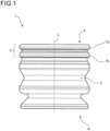
- Figure 1
- shows a schematic side view of a spring element according to a preferred embodiment,
- Figure 2
- shows a schematic cross sectional view through the spring element of
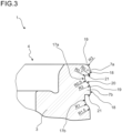
figure 1 , - Figure 3
- shows a schematic detail view of the spring element shown in
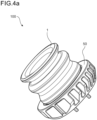
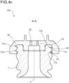
figure 2 , and - Figure 4a-c
- show schematic representations of a jounce bumper assembly having a spring element as shown in
figures 1 - 3 . - A
spring element 1 is shown infigure 1 . Thespring element 1 comprises a longitudinal axis L along which abase body 3 extends. Thebase body 3 is shown in the uncompressed base state. - The
base body 3 comprises abase end 4 and atip end 6. Thebase end 4, in operation, faces towards a vehicle structure to which thespring element 1 is mounted either immediately or through other parts. Thetip end 6, in operation, faces a damper cap or similar element which causes compression of the spring element upon impact. - On the side of the
base end 4, thebase body 3 comprises anend portion 5 configured from mounting thespring element 1 to a mounting cap (cf.figures 4a-c ). - The
end portion 5 comprises a plurality ofretention elements 7a, b that are axially spaced apart from one another in the direction of the longitudinal axis L. In the exemplary embodiment shown infigures 1 - 3 , theretention elements base body 3. It would however also be within the scope of the invention if one or both of theretention elements 7a, b were formed as segmented protrusions wherein each segment only extends along a portion of the circumference of thebase body 3 and in which the segments are preferably spaced apart from one another in the circumferential direction. - As can be seen in
figure 2 , thebase body 3 comprises arecess 9 extending from thebase end 4 through to thetip end 6. Therecess 9 comprises a stepped inner diameter having afirst stop shoulder 11 and acylindrical side wall 13. Thestop shoulder 11 andcylindrical side wall 13 are configured to receive and centre a mounting cap (cf.figures 4a-c ). The recess on thebase end 4 further comprises an inclined insertion surface, preferably having a conical or tapered surface portion which facilitates the installation of thespring element 1 on the mounting cap (cf.figures 4a-c ). - As can be seen from
figure 3 , theretention elements first retention element 7a is located on thebase end 4 of the spring element 7. Thesecond retention element 7b is spaced apart from thebase end 4 and from thefirst retention element 7a in the direction of the longitudinal axis L (seefigures 1 and2 ). - The
first retention element 7a comprises aperipheral surface 18 and atransition radius 19 providing a smooth transition between theperipheral surface 18 and thebase end 4. - The
second retention element 7b also comprises aperipheral surface 18, preferably having the same diameter as theperipheral surface 18 of thefirst retention element 7a. Facing thebase end 4, thesecond retention element 7b comprises afirst flank 20 which comprises a chamfered surface portion facing thebase end 4. The angle of the chamfer preferably is in a range between 15° and 60° with respect to the longitudinal axis, allowing theretention element 7b to be deflected and/or deformed radially inwards when pushing thespring element 1 into the mounting cap. Thefirst retention element 7a is also able to deflect and/or deform radially inwards by virtue of thetransition radius 19. - Both
retention elements 7a, b comprise asecond flank 21 facing away from thebase end 4. In the embodiment shown, the second 21 flank is oriented perpendicular to the longitudinal axis, i.e. parallel to a radial line towards the longitudinal axis L (cf.figures 1 ,2 ). - Alternatively, it would be within the scope of invention to have the
second flank 21 formed as an undercut. - The
second retention element 7b comprises atransition radius 19 in between thefirst flank 20 and theperipheral surface 18. Further preferably, bothretention elements 7a, b also comprise a transition radius from theperipheral surface 18 to thesecond flank 21. - The
first retention element 7a and thesecond retention element 7b are spaced apart in the axial direction by acylindrical wall section 17a. Relative to theperipheral surfaces 18 of theretention elements base body 3, thesurface portion 17a defines a recess. Facing away from thesecond flank 21 of the second retention element, thebase body 3 comprises a furthercylindrical portion 17b, which, again relative to theperipheral surfaces 18 of theretention elements - The function of
recesses spring element 1 can enter a positive engagement (cf.figs 4a-c ). Thesurface portions surface portions 17a, b might in fact also include non-cylindrical surface portions or might be entirely non-cylindrical, i.e. convex, concave or conical, or be formed as a combination of several of these shapes. Their key function, which will be contemplated in the context offigures 4a - c , is providing the volume necessary for the interengagement of thecorresponding retention elements 7a,b of thespring element 1 on the one hand side and the mounting cap on the other hand side. - While the
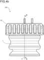
figures 1 - 3 mainly show thespring element 1 and details thereof in isolation,figures 4a-c illustrate the inventive use of thespring element 1 offigures 1 - 3 in ajounce bumper assembly 100. Thejounce bumper assembly 100 comprises thespring element 1 mounted into a mountingcap 50 as shown infigure 4a . The mountingcap 50 preferably is made partially or completely of a polymer, such as a thermoplastic material, for example polyoxymethylene (POM), or partially of completely made of metal. The outer contour of the mountingcap 50, which preferably acts as a spacer between the vehicle structure (not shown) and thespring element 1 may be substantially cylindrical or may be oblong, depending on the space constraints of the mounting environment of thejounce bumper assembly 100. - A cross sectional view through the jounce bumper assembly of
figures 4a ,4b is shown infigure 4c . Fromfigure 4c it is apparent that in addition to the mountingcap 50 and thespring element 1, thejounce bumper assembly 100 also comprises asleeve insert 52 that is added to the mountingcap 50 for installation purposes. - The mounting
cap 50 comprises a firstannular recess 51a and, spaced apart therefrom, a secondannular recess 51b. Therecesses 51a, b are configured to receive the first andsecond retention elements 7a, b of thespring element 1. - Likewise, the mounting
cap 50 comprises a number of protrusions having acontact flank 53, respectively. The protrusions and contact flanks 53 are spaced apart from one another in the direction of the longitudinal axis L such that theretention elements cap 50, and such that thesurface portions retention elements recesses 51a, b preferably is minimally smaller, at least in the axial direction (direction of the longitudinal axis L), as compared to the axial extension of theretention elements retention elements cap 50. - While the embodiment shown in
figures 1 - 4c , for ease of understanding, only shows a jounce bumper assembly and spring element having exactly two retention elements spaced apart from one another in the direction of the longitudinal axis, the invention contemplates that also a higher number of retention elements may be present of the spring element and correspondingly on the mounting cap, with each retention element being spaced apart from other retention elements in the direction of the longitudinal axis L. - Also, while the figures only show the use of one-piece retention elements that extend along the entire circumference of the base body, respectively, it is within the invention that at least one, preferably each, retention element is composed of a plurality of segments that are spaced apart from one another in the circumferential direction, wherein the segments of one retention element are axially spaced apart from a second retention element, or a plurality of segments, for that matter.
Claims (12)
- A spring element (1), in particular jounce bumper, for a vehicle suspension, comprising:a longitudinal axis (L) and a base body (3) extending along the longitudinal axis (L), the base body (3) being elastically deformable between an uncompressed basic state and a compressed state in which the base body (3) is at least partially compressed in the direction of the longitudinal axis (L),an end portion (5) positioned on a base end (4) of the base body, said end portion being configured for mounting the base body (3) in a mounting cap (50); whereinthe end portion (5) comprises a plurality of at least two radially extending retention elements (7a,b) that are spaced apart from one another in the direction of the longitudinal axis (L), and each of the retention elements (7a, b) being configured to engage a mating retention element (17a, 17b) provided on the mounting cap (50), characterised in that the mating retention elements are configured to engage one another in a positive fit, preferably such that the retention elements provided on the base body are elastically deformable between an uncompressed basic state and a compressed state, and further preferably that the retention elements provided on the base body are oversized when compared to the mating retention elements of the mounting cap..
- The spring element of claim 1,
wherein the mating relationship between the retention elements is such that one type of retention elements is formed as a protrusion while the other type of retention elements, is formed as a recess that is dimensioned to accommodate the protrusion. - The spring element (1) of any one of claims 1 to 2,
wherein at least one of the retention elements (7a, b) is formed as a number of segments, preferably, lip segments, each extending along a portion of the circumference of the base body (3). - The spring element (1) of any one of the preceding claims,
wherein one retention element (7a, b) is positioned at the base end (4) of the base body (3). - The spring element (1) of any one of the preceding claims,
wherein at least one of the retention elements (7a, b) defines a first flank (20) facing the base end (4) and a second flank (21) facing away from the base end (4). - The spring element (1) of claim 5,
wherein the first flank (20) comprises a chamfered surface portion. - The spring element (1) of claim 5 or 6,
wherein the second flank (21) comprises a surface portion that is extending radially with respect to the longitudinal axis (L), or that is undercut. - The spring element (1) of any one of the preceding claims,
wherein the base body (3) comprises an outside surface, the retention elements (7a, b) protrude from the outside surface and connect to the base body (3) through a transition radius (19), wherein the transition radius (19) preferably is in a range of 0,1 mm or greater. - The spring element (1) of any one of claims 4 to 8,
wherein the retention elements (7a, b) comprise a peripheral surface (18), and the chamfered surface connects to the peripheral surface (18) through a transition radius (19), said radius preferably being in a range of 0,1 mm or greater. - The spring element (1) of any one of the preceding claims,
wherein the base body (3) is partly or completely composed of an elastomer that is compressible in volume, preferably of a cellular polyisocyanate polyaddition product. - A jounce bumper assembly (100), havinga mounting cap (50) anda spring element (1) mounted in the mounting cap (50),characterized in that the spring element (1) is formed in accordance with any one of the preceding claims, and the mounting cap (50) comprises a number of retention elements (7a, b) matingly corresponding to and in engagement with the retention elements (7a, b) of the spring element (1).
- A vehicle, comprisinga number of vehicle suspensions, whereinat least one of the suspensions, preferably some or all of the suspensions, comprises a jounce bumper assembly (100) as claimed in claim 11.
Applications Claiming Priority (2)
| Application Number | Priority Date | Filing Date | Title |
|---|---|---|---|
| EP19177983 | 2019-06-03 | ||
| PCT/EP2020/065345 WO2020245196A1 (en) | 2019-06-03 | 2020-06-03 | Spring element, in particular jounce bumper, for a vehicle suspension |
Publications (2)
| Publication Number | Publication Date |
|---|---|
| EP3976989A1 EP3976989A1 (en) | 2022-04-06 |
| EP3976989B1 true EP3976989B1 (en) | 2023-08-09 |
Family
ID=66751932
Family Applications (1)
| Application Number | Title | Priority Date | Filing Date |
|---|---|---|---|
| EP20730265.4A Active EP3976989B1 (en) | 2019-06-03 | 2020-06-03 | Spring element, in particular jounce bumper, for a vehicle suspension |
Country Status (4)
| Country | Link |
|---|---|
| US (1) | US11667169B2 (en) |
| EP (1) | EP3976989B1 (en) |
| CN (1) | CN113950588A (en) |
| WO (1) | WO2020245196A1 (en) |
Family Cites Families (14)
| Publication number | Priority date | Publication date | Assignee | Title |
|---|---|---|---|---|
| US2951674A (en) | 1957-09-23 | 1960-09-06 | Gen Motors Corp | Shockproof mounting |
| DE1272049B (en) * | 1966-08-17 | 1968-07-04 | Anton Klocke G M B H | Elastic bearing adjustable in height |
| US4350777A (en) | 1980-03-28 | 1982-09-21 | Bayer Aktiengesellschaft | Impermeable molded articles of cellular polyurethane elastomers produced with organofunctional polysiloxane-derivatives and their use as spring elements |
| DE3113690A1 (en) | 1981-04-04 | 1982-10-28 | Elastogran GmbH, 2844 Lemförde | "METHOD FOR PRODUCING CLOSED-CELL POLYURETHANE MOLDED PARTS WITH A COMPRESSED EDGE ZONE" |
| DE3621040A1 (en) | 1986-06-24 | 1988-01-07 | Bayer Ag | METHOD FOR THE PRODUCTION AND POLYSILOXANE IONOMERS, POLYSILOXAN IONOMERS AND THE USE THEREOF FOR THE PRODUCTION OF CELLED POLYURETHANE ELASTOMERS |
| DE19548771A1 (en) | 1995-12-23 | 1997-06-26 | Basf Ag | Microcellular polyurethane elastomer containing urea groups |
| DE19548770A1 (en) | 1995-12-23 | 1997-06-26 | Basf Ag | Microcellular polyurethane elastomer containing urea groups |
| JP2002039267A (en) | 2000-07-31 | 2002-02-06 | Kioritz Corp | Vibration control member and vibration control equipment |
| US6502883B2 (en) * | 2000-12-04 | 2003-01-07 | Cooper Technology Services, Llc | Two stage body mount rebound cushion |
| US6619635B1 (en) * | 2002-04-08 | 2003-09-16 | Bfs Diversified Products, Llc | Air spring clamping assembly |
| DE20311242U1 (en) * | 2003-07-21 | 2003-09-18 | Basf Ag | Spring unit comprises a hollow cylindrical damping element on the basis of polycyanate polyaddition products, with one of its ends constituted as a circumferential lip |
| JP5766836B1 (en) * | 2014-03-12 | 2015-08-19 | 住友理工株式会社 | Dust cover assembly for vehicle and method for manufacturing the same |
| JP2019521290A (en) * | 2016-05-27 | 2019-07-25 | ビーエーエスエフ ソシエタス・ヨーロピアBasf Se | Vehicle shock absorber spring element and vehicle equipped with vehicle shock absorber and vehicle shock absorber |
| AU2017289294B2 (en) * | 2016-06-30 | 2023-01-19 | Air Diffusion Agencies Pty Ltd | Mount improvements |
-
2020
- 2020-06-03 EP EP20730265.4A patent/EP3976989B1/en active Active
- 2020-06-03 CN CN202080041574.7A patent/CN113950588A/en active Pending
- 2020-06-03 WO PCT/EP2020/065345 patent/WO2020245196A1/en active Search and Examination
- 2020-06-03 US US17/615,819 patent/US11667169B2/en active Active
Also Published As
| Publication number | Publication date |
|---|---|
| US20220281277A1 (en) | 2022-09-08 |
| US11667169B2 (en) | 2023-06-06 |
| WO2020245196A1 (en) | 2020-12-10 |
| CN113950588A (en) | 2022-01-18 |
| EP3976989A1 (en) | 2022-04-06 |
Similar Documents
| Publication | Publication Date | Title |
|---|---|---|
| JP5766836B1 (en) | Dust cover assembly for vehicle and method for manufacturing the same | |
| US8789820B2 (en) | Damper bearing with tapering end faces and method for the production thereof | |
| EP4107408B1 (en) | Jounce bumper assembly and suspension system | |
| JP2014062560A (en) | Dust cover assembly for vehicle and method of manufacturing the same | |
| EP3976989B1 (en) | Spring element, in particular jounce bumper, for a vehicle suspension | |
| US11255402B2 (en) | Spring element for a vehicle shock absorber, and vehicle shock absorber and vehicle having same | |
| EP3976988B1 (en) | Spring element, in particular jounce bumper, for a vehicle suspension | |
| EP3969779B1 (en) | Spring element, in particular jounce bumper, for a vehicle shock absorber | |
| US20120043708A1 (en) | Damping element having a wavy supporting ring | |
| EP3969778B1 (en) | Spring element, in particular jounce bumper, for a vehicle shock absorber | |
| WO2011130909A1 (en) | Damper bearing with tapering end faces and method for production thereof | |
| EP4069992A1 (en) | Jounce bumper of an automotive vehicle suspension system, and method of producing such a jounce bumper | |
| EP4170194A1 (en) | Damper inlay for a vehicle and a vehicle comprising said damper inlay | |
| CN110573361A (en) | Spring support designed to receive a helical spring of a motor vehicle spring system, motor vehicle spring system and use of a spring support | |
| EP4230429A1 (en) | A damper inlay for a vehicle and a vehicle comprising said damper inlay | |
| CN115066568A (en) | Jounce bumper support ring for suspension system, jounce bumper assembly and use thereof | |
| WO2024028097A1 (en) | Bush |
Legal Events
| Date | Code | Title | Description |
|---|---|---|---|
| STAA | Information on the status of an ep patent application or granted ep patent |
Free format text: STATUS: UNKNOWN |
|
| STAA | Information on the status of an ep patent application or granted ep patent |
Free format text: STATUS: THE INTERNATIONAL PUBLICATION HAS BEEN MADE |
|
| PUAI | Public reference made under article 153(3) epc to a published international application that has entered the european phase |
Free format text: ORIGINAL CODE: 0009012 |
|
| STAA | Information on the status of an ep patent application or granted ep patent |
Free format text: STATUS: REQUEST FOR EXAMINATION WAS MADE |
|
| 17P | Request for examination filed |
Effective date: 20220103 |
|
| AK | Designated contracting states |
Kind code of ref document: A1 Designated state(s): AL AT BE BG CH CY CZ DE DK EE ES FI FR GB GR HR HU IE IS IT LI LT LU LV MC MK MT NL NO PL PT RO RS SE SI SK SM TR |
|
| DAV | Request for validation of the european patent (deleted) | ||
| DAX | Request for extension of the european patent (deleted) | ||
| GRAP | Despatch of communication of intention to grant a patent |
Free format text: ORIGINAL CODE: EPIDOSNIGR1 |
|
| STAA | Information on the status of an ep patent application or granted ep patent |
Free format text: STATUS: GRANT OF PATENT IS INTENDED |
|
| INTG | Intention to grant announced |
Effective date: 20230324 |
|
| GRAS | Grant fee paid |
Free format text: ORIGINAL CODE: EPIDOSNIGR3 |
|
| GRAA | (expected) grant |
Free format text: ORIGINAL CODE: 0009210 |
|
| STAA | Information on the status of an ep patent application or granted ep patent |
Free format text: STATUS: THE PATENT HAS BEEN GRANTED |
|
| AK | Designated contracting states |
Kind code of ref document: B1 Designated state(s): AL AT BE BG CH CY CZ DE DK EE ES FI FR GB GR HR HU IE IS IT LI LT LU LV MC MK MT NL NO PL PT RO RS SE SI SK SM TR |
|
| REG | Reference to a national code |
Ref country code: GB Ref legal event code: FG4D |
|
| REG | Reference to a national code |
Ref country code: CH Ref legal event code: EP |
|
| REG | Reference to a national code |
Ref country code: DE Ref legal event code: R096 Ref document number: 602020015451 Country of ref document: DE |
|
| REG | Reference to a national code |
Ref country code: IE Ref legal event code: FG4D |
|
| REG | Reference to a national code |
Ref country code: LT Ref legal event code: MG9D |
|
| REG | Reference to a national code |
Ref country code: NL Ref legal event code: MP Effective date: 20230809 |
|
| REG | Reference to a national code |
Ref country code: AT Ref legal event code: MK05 Ref document number: 1597846 Country of ref document: AT Kind code of ref document: T Effective date: 20230809 |
|
| PG25 | Lapsed in a contracting state [announced via postgrant information from national office to epo] |
Ref country code: GR Free format text: LAPSE BECAUSE OF FAILURE TO SUBMIT A TRANSLATION OF THE DESCRIPTION OR TO PAY THE FEE WITHIN THE PRESCRIBED TIME-LIMIT Effective date: 20231110 |
|
| PG25 | Lapsed in a contracting state [announced via postgrant information from national office to epo] |
Ref country code: IS Free format text: LAPSE BECAUSE OF FAILURE TO SUBMIT A TRANSLATION OF THE DESCRIPTION OR TO PAY THE FEE WITHIN THE PRESCRIBED TIME-LIMIT Effective date: 20231209 |
|
| PG25 | Lapsed in a contracting state [announced via postgrant information from national office to epo] |
Ref country code: SE Free format text: LAPSE BECAUSE OF FAILURE TO SUBMIT A TRANSLATION OF THE DESCRIPTION OR TO PAY THE FEE WITHIN THE PRESCRIBED TIME-LIMIT Effective date: 20230809 Ref country code: RS Free format text: LAPSE BECAUSE OF FAILURE TO SUBMIT A TRANSLATION OF THE DESCRIPTION OR TO PAY THE FEE WITHIN THE PRESCRIBED TIME-LIMIT Effective date: 20230809 Ref country code: PT Free format text: LAPSE BECAUSE OF FAILURE TO SUBMIT A TRANSLATION OF THE DESCRIPTION OR TO PAY THE FEE WITHIN THE PRESCRIBED TIME-LIMIT Effective date: 20231211 Ref country code: NO Free format text: LAPSE BECAUSE OF FAILURE TO SUBMIT A TRANSLATION OF THE DESCRIPTION OR TO PAY THE FEE WITHIN THE PRESCRIBED TIME-LIMIT Effective date: 20231109 Ref country code: NL Free format text: LAPSE BECAUSE OF FAILURE TO SUBMIT A TRANSLATION OF THE DESCRIPTION OR TO PAY THE FEE WITHIN THE PRESCRIBED TIME-LIMIT Effective date: 20230809 Ref country code: LV Free format text: LAPSE BECAUSE OF FAILURE TO SUBMIT A TRANSLATION OF THE DESCRIPTION OR TO PAY THE FEE WITHIN THE PRESCRIBED TIME-LIMIT Effective date: 20230809 Ref country code: LT Free format text: LAPSE BECAUSE OF FAILURE TO SUBMIT A TRANSLATION OF THE DESCRIPTION OR TO PAY THE FEE WITHIN THE PRESCRIBED TIME-LIMIT Effective date: 20230809 Ref country code: IS Free format text: LAPSE BECAUSE OF FAILURE TO SUBMIT A TRANSLATION OF THE DESCRIPTION OR TO PAY THE FEE WITHIN THE PRESCRIBED TIME-LIMIT Effective date: 20231209 Ref country code: HR Free format text: LAPSE BECAUSE OF FAILURE TO SUBMIT A TRANSLATION OF THE DESCRIPTION OR TO PAY THE FEE WITHIN THE PRESCRIBED TIME-LIMIT Effective date: 20230809 Ref country code: GR Free format text: LAPSE BECAUSE OF FAILURE TO SUBMIT A TRANSLATION OF THE DESCRIPTION OR TO PAY THE FEE WITHIN THE PRESCRIBED TIME-LIMIT Effective date: 20231110 Ref country code: FI Free format text: LAPSE BECAUSE OF FAILURE TO SUBMIT A TRANSLATION OF THE DESCRIPTION OR TO PAY THE FEE WITHIN THE PRESCRIBED TIME-LIMIT Effective date: 20230809 Ref country code: AT Free format text: LAPSE BECAUSE OF FAILURE TO SUBMIT A TRANSLATION OF THE DESCRIPTION OR TO PAY THE FEE WITHIN THE PRESCRIBED TIME-LIMIT Effective date: 20230809 |
|
| PG25 | Lapsed in a contracting state [announced via postgrant information from national office to epo] |
Ref country code: PL Free format text: LAPSE BECAUSE OF FAILURE TO SUBMIT A TRANSLATION OF THE DESCRIPTION OR TO PAY THE FEE WITHIN THE PRESCRIBED TIME-LIMIT Effective date: 20230809 |
|
| PG25 | Lapsed in a contracting state [announced via postgrant information from national office to epo] |
Ref country code: ES Free format text: LAPSE BECAUSE OF FAILURE TO SUBMIT A TRANSLATION OF THE DESCRIPTION OR TO PAY THE FEE WITHIN THE PRESCRIBED TIME-LIMIT Effective date: 20230809 |
|
| PG25 | Lapsed in a contracting state [announced via postgrant information from national office to epo] |
Ref country code: SM Free format text: LAPSE BECAUSE OF FAILURE TO SUBMIT A TRANSLATION OF THE DESCRIPTION OR TO PAY THE FEE WITHIN THE PRESCRIBED TIME-LIMIT Effective date: 20230809 Ref country code: RO Free format text: LAPSE BECAUSE OF FAILURE TO SUBMIT A TRANSLATION OF THE DESCRIPTION OR TO PAY THE FEE WITHIN THE PRESCRIBED TIME-LIMIT Effective date: 20230809 Ref country code: ES Free format text: LAPSE BECAUSE OF FAILURE TO SUBMIT A TRANSLATION OF THE DESCRIPTION OR TO PAY THE FEE WITHIN THE PRESCRIBED TIME-LIMIT Effective date: 20230809 Ref country code: EE Free format text: LAPSE BECAUSE OF FAILURE TO SUBMIT A TRANSLATION OF THE DESCRIPTION OR TO PAY THE FEE WITHIN THE PRESCRIBED TIME-LIMIT Effective date: 20230809 Ref country code: DK Free format text: LAPSE BECAUSE OF FAILURE TO SUBMIT A TRANSLATION OF THE DESCRIPTION OR TO PAY THE FEE WITHIN THE PRESCRIBED TIME-LIMIT Effective date: 20230809 Ref country code: CZ Free format text: LAPSE BECAUSE OF FAILURE TO SUBMIT A TRANSLATION OF THE DESCRIPTION OR TO PAY THE FEE WITHIN THE PRESCRIBED TIME-LIMIT Effective date: 20230809 Ref country code: SK Free format text: LAPSE BECAUSE OF FAILURE TO SUBMIT A TRANSLATION OF THE DESCRIPTION OR TO PAY THE FEE WITHIN THE PRESCRIBED TIME-LIMIT Effective date: 20230809 |