EP4170129B1 - Rotationsverdichter - Google Patents
Rotationsverdichter Download PDFInfo
- Publication number
- EP4170129B1 EP4170129B1 EP22198676.3A EP22198676A EP4170129B1 EP 4170129 B1 EP4170129 B1 EP 4170129B1 EP 22198676 A EP22198676 A EP 22198676A EP 4170129 B1 EP4170129 B1 EP 4170129B1
- Authority
- EP
- European Patent Office
- Prior art keywords
- guide portion
- outflow
- outflow guide
- roller
- discharge
- Prior art date
- Legal status (The legal status is an assumption and is not a legal conclusion. Google has not performed a legal analysis and makes no representation as to the accuracy of the status listed.)
- Active
Links
Images


Classifications
-
- F—MECHANICAL ENGINEERING; LIGHTING; HEATING; WEAPONS; BLASTING
- F04—POSITIVE - DISPLACEMENT MACHINES FOR LIQUIDS; PUMPS FOR LIQUIDS OR ELASTIC FLUIDS
- F04C—ROTARY-PISTON, OR OSCILLATING-PISTON, POSITIVE-DISPLACEMENT MACHINES FOR LIQUIDS; ROTARY-PISTON, OR OSCILLATING-PISTON, POSITIVE-DISPLACEMENT PUMPS
- F04C18/00—Rotary-piston pumps specially adapted for elastic fluids
- F04C18/30—Rotary-piston pumps specially adapted for elastic fluids having the characteristics covered by two or more of groups F04C18/02, F04C18/08, F04C18/22, F04C18/24, F04C18/48, or having the characteristics covered by one of these groups together with some other type of movement between co-operating members
- F04C18/34—Rotary-piston pumps specially adapted for elastic fluids having the characteristics covered by two or more of groups F04C18/02, F04C18/08, F04C18/22, F04C18/24, F04C18/48, or having the characteristics covered by one of these groups together with some other type of movement between co-operating members having the movement defined in group F04C18/08 or F04C18/22 and relative reciprocation between the co-operating members
- F04C18/356—Rotary-piston pumps specially adapted for elastic fluids having the characteristics covered by two or more of groups F04C18/02, F04C18/08, F04C18/22, F04C18/24, F04C18/48, or having the characteristics covered by one of these groups together with some other type of movement between co-operating members having the movement defined in group F04C18/08 or F04C18/22 and relative reciprocation between the co-operating members with vanes reciprocating with respect to the outer member
- F04C18/3568—Rotary-piston pumps specially adapted for elastic fluids having the characteristics covered by two or more of groups F04C18/02, F04C18/08, F04C18/22, F04C18/24, F04C18/48, or having the characteristics covered by one of these groups together with some other type of movement between co-operating members having the movement defined in group F04C18/08 or F04C18/22 and relative reciprocation between the co-operating members with vanes reciprocating with respect to the outer member with axially movable vanes
-
- F—MECHANICAL ENGINEERING; LIGHTING; HEATING; WEAPONS; BLASTING
- F01—MACHINES OR ENGINES IN GENERAL; ENGINE PLANTS IN GENERAL; STEAM ENGINES
- F01C—ROTARY-PISTON OR OSCILLATING-PISTON MACHINES OR ENGINES
- F01C21/00—Component parts, details or accessories not provided for in groups F01C1/00 - F01C20/00
- F01C21/08—Rotary pistons
-
- F—MECHANICAL ENGINEERING; LIGHTING; HEATING; WEAPONS; BLASTING
- F04—POSITIVE - DISPLACEMENT MACHINES FOR LIQUIDS; PUMPS FOR LIQUIDS OR ELASTIC FLUIDS
- F04C—ROTARY-PISTON, OR OSCILLATING-PISTON, POSITIVE-DISPLACEMENT MACHINES FOR LIQUIDS; ROTARY-PISTON, OR OSCILLATING-PISTON, POSITIVE-DISPLACEMENT PUMPS
- F04C18/00—Rotary-piston pumps specially adapted for elastic fluids
- F04C18/30—Rotary-piston pumps specially adapted for elastic fluids having the characteristics covered by two or more of groups F04C18/02, F04C18/08, F04C18/22, F04C18/24, F04C18/48, or having the characteristics covered by one of these groups together with some other type of movement between co-operating members
- F04C18/34—Rotary-piston pumps specially adapted for elastic fluids having the characteristics covered by two or more of groups F04C18/02, F04C18/08, F04C18/22, F04C18/24, F04C18/48, or having the characteristics covered by one of these groups together with some other type of movement between co-operating members having the movement defined in group F04C18/08 or F04C18/22 and relative reciprocation between the co-operating members
- F04C18/344—Rotary-piston pumps specially adapted for elastic fluids having the characteristics covered by two or more of groups F04C18/02, F04C18/08, F04C18/22, F04C18/24, F04C18/48, or having the characteristics covered by one of these groups together with some other type of movement between co-operating members having the movement defined in group F04C18/08 or F04C18/22 and relative reciprocation between the co-operating members with vanes reciprocating with respect to the inner member
-
- F—MECHANICAL ENGINEERING; LIGHTING; HEATING; WEAPONS; BLASTING
- F04—POSITIVE - DISPLACEMENT MACHINES FOR LIQUIDS; PUMPS FOR LIQUIDS OR ELASTIC FLUIDS
- F04C—ROTARY-PISTON, OR OSCILLATING-PISTON, POSITIVE-DISPLACEMENT MACHINES FOR LIQUIDS; ROTARY-PISTON, OR OSCILLATING-PISTON, POSITIVE-DISPLACEMENT PUMPS
- F04C29/00—Component parts, details or accessories of pumps or pumping installations, not provided for in groups F04C18/00 - F04C28/00
- F04C29/12—Arrangements for admission or discharge of the working fluid, e.g. constructional features of the inlet or outlet
- F04C29/124—Arrangements for admission or discharge of the working fluid, e.g. constructional features of the inlet or outlet with inlet and outlet valves specially adapted for rotary or oscillating piston pumps
- F04C29/126—Arrangements for admission or discharge of the working fluid, e.g. constructional features of the inlet or outlet with inlet and outlet valves specially adapted for rotary or oscillating piston pumps of the non-return type
-
- F—MECHANICAL ENGINEERING; LIGHTING; HEATING; WEAPONS; BLASTING
- F04—POSITIVE - DISPLACEMENT MACHINES FOR LIQUIDS; PUMPS FOR LIQUIDS OR ELASTIC FLUIDS
- F04C—ROTARY-PISTON, OR OSCILLATING-PISTON, POSITIVE-DISPLACEMENT MACHINES FOR LIQUIDS; ROTARY-PISTON, OR OSCILLATING-PISTON, POSITIVE-DISPLACEMENT PUMPS
- F04C2240/00—Components
- F04C2240/20—Rotors
-
- F—MECHANICAL ENGINEERING; LIGHTING; HEATING; WEAPONS; BLASTING
- F04—POSITIVE - DISPLACEMENT MACHINES FOR LIQUIDS; PUMPS FOR LIQUIDS OR ELASTIC FLUIDS
- F04C—ROTARY-PISTON, OR OSCILLATING-PISTON, POSITIVE-DISPLACEMENT MACHINES FOR LIQUIDS; ROTARY-PISTON, OR OSCILLATING-PISTON, POSITIVE-DISPLACEMENT PUMPS
- F04C2240/00—Components
- F04C2240/50—Bearings
-
- F—MECHANICAL ENGINEERING; LIGHTING; HEATING; WEAPONS; BLASTING
- F04—POSITIVE - DISPLACEMENT MACHINES FOR LIQUIDS; PUMPS FOR LIQUIDS OR ELASTIC FLUIDS
- F04C—ROTARY-PISTON, OR OSCILLATING-PISTON, POSITIVE-DISPLACEMENT MACHINES FOR LIQUIDS; ROTARY-PISTON, OR OSCILLATING-PISTON, POSITIVE-DISPLACEMENT PUMPS
- F04C23/00—Combinations of two or more pumps, each being of rotary-piston or oscillating-piston type, specially adapted for elastic fluids; Pumping installations specially adapted for elastic fluids; Multi-stage pumps specially adapted for elastic fluids
- F04C23/001—Combinations of two or more pumps, each being of rotary-piston or oscillating-piston type, specially adapted for elastic fluids; Pumping installations specially adapted for elastic fluids; Multi-stage pumps specially adapted for elastic fluids of similar working principle
Definitions
- the present disclosure relates to a vane rotary compressor in which a vane is slidably inserted into a rotating roller.
- Rotary compressors may be classified into a type in which a vane is slidably inserted into a cylinder to be brought into contact with a roller, and another type in which a vane is slidably inserted into a roller to be brought into contact with a cylinder.
- the former is called an eccentric rotary compressor, and the latter is classified as a vane rotary compressor (or concentric rotary compressor).
- the vane inserted in the cylinder is pulled out toward the roller by elastic force or back pressure to be brought into contact with an outer circumferential surface of the roller.
- the vane rotary compressor the vane inserted in the roller is pulled out toward the cylinder by centrifugal force and back pressure while rotating together with the roller, so as to be brought into contact with an inner circumferential surface of the cylinder.
- the eccentric rotary compressor independently forms as many compression chambers as the number of vanes per revolution of the roller, and the respective compression chambers simultaneously perform suction, compression, and discharge strokes.
- the vane rotary compressor continuously forms as many compression chambers as the number of vanes per revolution of the roller, and the respective compression chambers sequentially perform suction, compression, and discharge strokes. Accordingly, the vane rotary compressor has a higher compression ratio than the eccentric rotary compressor. Therefore, the vane rotary compressor is more suitable for high pressure refrigerants such as R32, R410a, and CO 2 , which have low ozone depletion potential (ODP) and global warming index (GWP).
- ODP ozone depletion potential
- GWP global warming index
- Patent Document 1 U.S. Patent Publication No. US 2014/0369878 A1
- Patent Document 2 Japanese Patent Application Laid-Open No. 2000-265984
- Patent Document 3 Japanese Patent Application Laid-Open No. 2013-72429
- a contact point at which an outer circumferential surface of the roller and an inner circumferential surface of the cylinder are substantially in contact with each other is located between a discharge port and a suction port, so as to separate the discharge port and the suction port from each other.
- JP S57 146088 A provides a rotary compressor.
- Discharge ports are formed symmetrically in a rear side block at the portions thereof facing a rotor.
- the pocket is closed by the block and a cylinder chamber is under the compression process.
- the port begins to communicate with the pocket, whereupon high-pressure gas beings to be discharged from the port.
- the rotor is further turned and the pocket comes out of the port, communication between the port and pocket is interrupted and the discharge process of the compressor is terminated.
- CN 111 963 431 A discloses a compressor and air conditioner.
- CN 111 963 429 A related to a pump body assembly, compressor and air conditioner.
- CN 114 151 347 A relates to compressors, in particular to a cylinder, a pump body structure, a compressor and an air conditioner.
- a rotary compressor includes a casing, a cylinder, a roller, a vane, a main bearing, a sub bearing, and an outflow passage.
- the casing has an (e.g. hermetic) inner space.
- the cylinder is disposed in the inner space of the casing to define a compression space.
- the roller is disposed on a rotating shaft so as to be rotatable in the inner space of the cylinder and eccentrically located with respect to a center of the compression space to have a contact point close to an inner circumferential surface of the cylinder.
- the vane is slidably inserted into a vane slot provided in the roller to rotate together with the roller.
- the main bearing and the sub bearing is disposed on both sides of the cylinder in the axial direction to form the compression space together with the cylinder.
- a portion of the outflow passage may be formed through the roller.
- the outflow passage may connect the compression space and the inner space of the casing to allow refrigerant to flow therethrough from the compression space to the inner space.
- a residual space after a discharge stroke or a compression space in the course of a discharge stroke can periodically communicate with the inner space of the casing according to a rotation angle of the roller.
- This can simplify a structure of the cylinder to easily process the cylinder, and lower surface pressure between the vane and the cylinder around a discharge hole to reduce chattering of the vane, thereby suppressing wear and vibration noise between the vane and the cylinder.
- refrigerant remaining in the residual space can flow out or refrigerant in the course of a discharge stroke can be quickly discharged, thereby reducing an amount of refrigerant remaining in the compression space.
- a pressure difference between front and rear sides of the vane can also be reduced, thereby reducing wear and vibration noise due to chattering of the vane.
- the outflow passage may be periodically open according to the rotation of the roller.
- refrigerant after a discharge stroke or in the course of the discharge stroke can flow out periodically while refrigerant before the discharge stroke can be prevented from being discharged in advance, thereby preventing under-compression.
- the outflow passage may be provided in plurality at equal intervals along a circumferential direction of the roller.
- the outflow passages may be open with the same rotation angle, so that refrigerant after a discharge stroke or in the course of the discharge stroke can periodically flow out at equal intervals.
- a plurality of vane slots may be formed in the roller along a circumferential direction. Portions of the outflow passage may be formed between adjacent vane slots of the plurality of vane slots, respectively. With the configuration, refrigerant compressed in each compression chamber can periodically flow out through each outflow passage according to the rotation angle of the roller.
- a rotary compressor includes a casing, a cylinder, a roller, a vane, a main bearing, a sub bearing, and an outflow passage.
- the casing has an inner space, e.g. a hermetic inner space.
- the cylinder is disposed in the inner space of the casing to define a compression space.
- the roller is disposed on a rotating shaft so as to be rotatable in the cylinder and eccentrically located with respect to a center of the compression space to have a contact point close to an inner circumferential surface of the cylinder.
- the vane is slidably inserted into a vane slot provided in the roller to rotate together with the roller.
- the main bearing and the sub bearing is disposed on both sides of the cylinder in the axial direction to form the compression space together with the cylinder.
- the outflow passage may connect the compression space and the inner space of the casing to allow refrigerant to flow therethrough from the compression space to the inner space.
- the outflow passage includes a first outflow guide portion, a second outflow guide portion, and a third outflow guide portion through which refrigerant can flow from the compression space to the inner space of the casing.
- the first outflow guide portion may be disposed in the main bearing or the sub bearing.
- the second outflow guide portion may be formed through between both axial ends of the roller, e.g. in the axial direction, and communicate with the first outflow guide portion.
- the third outflow guide portion may be disposed in a bearing opposite to the bearing provided with the first outflow guide portion based on the roller, and communicate with the first outflow guide portion through the second outflow guide portion.
- a rotary compressor includes a casing; a cylinder disposed in the casing and defining a compression space therein; a main bearing and a sub bearing disposed on opposite sides of the cylinder in axial direction to define the compression space together with the cylinder; a roller eccentrically located in the compression space and disposed on a rotating shaft so as to be rotatable in the compression space of the cylinder; a vane slidably inserted into a vane slot provided in the roller to rotate together with the roller; and an outflow passage to allow (e.g. residual) refrigerant to flow out from the compression space.
- the outflow passage comprises: a first outflow guide portion disposed in one of the main bearing and the sub bearing and communicating with the compression space; a second outflow guide portion penetrating the roller from a first surface of the roller to a second surface thereof, the second surface being opposite to the first surface in axial direction, and a third outflow guide portion disposed in the other one of the main bearing and the sub bearing.
- the second outflow guide portion may be configured to communicate (e.g.: periodically or depending on a rotation angle or rotational position of the roller) with the first outflow guide portion and/or the third outflow guide portion.
- the second outflow guide portion may be configured to (e.g.: periodically or depending on a rotation angle or rotational position of the roller) connect the first outflow guide portion and the third outflow guide portion to each other, i.e. to make the first outflow guide portion communicate with the third outflow guide portion.
- the outflow passage may be connecting the compression space with a space outside the compression space, e.g. with an inner space of the casing, or a space between the casing and the main or sub bearing.
- refrigerant remaining in a residual space can flow out so as to decrease an amount refrigerant remaining in the compression space, and an effective discharge area can substantially increase such that compressed refrigerant can flow out quickly, thereby reducing an amount of residual refrigerant and improving compression efficiency.
- a pressure difference on a front surface of a vane can be eliminated, which may result in suppressing vane jumping, thereby reducing wear of the vane or the cylinder.
- leakage of refrigerant can be suppressed during a compression stroke, resulting in preventing an occurrence of under-compression.
- axial direction may refer to a direction parallel to the rotating shaft and/or to a direction parallel to rotation axis of the rotating shaft and/or of the roller.
- Circumferential direction may correspondingly refer to a direction in a plane perpendicular to the rotating shaft and/or rotation axis.
- Radial direction may be defined with respect to a center of the roller and/or to a center of the rotation shaft and/or to the rotation axis.
- the indications may refer to a cylindrical coordinate system.
- the rotary compressor according to any one of the preceding aspects may include one or more of the following features:
- the third outflow guide portion may be communicating with a space outside the compression space, i.e. an inner space of the casing.
- the cylinder may have an open upper/first surface (i.e. top base surface) and/or an open lower/second surface (i.e. bottom base surface) in axial direction.
- the upper/first surface may be closed or covered by the main bearing and/or the lower/second surface may be closed or covered by the sub bearing.
- the rotating shaft may be connected to a driving motor of the compressor.
- the roller may have a cylindrical shape and/or a circular cross-section (i.e. perpendicular to the rotation axis or rotating shaft).
- the roller in particular a first surface (i.e. upper surface or top base surface) and a second surface (i.e. lower surface or bottom base surface) thereof, may be in contact with or adjacent to the main bearing and the sub bearing.
- the vane slot may extend from a circumferential surface of the roller towards an inside thereof. The vane slot may form an angle with a radial direction.
- the first surface of the roller may be facing the main bearing, and the second surface of the roller may be facing the sub bearing.
- the first and/or second surface may extend in a plane perpendicular to the rotation axis or to the rotating shaft.
- the second outflow guide portion may be disposed in the rotatable roller eccentrically with respect to a center of the roller and/or with respect to the rotating shaft and/or with respect to the rotation axis.
- the second outflow guide portion may be configured to change its position with respect to the first and/or third outflow guide portion, e.g. depending on a rotation angle or rotational position of the roller.
- the second outflow guide portion may periodically communicate with the first outflow guide portion. This can reduce an amount of residual refrigerant and suppress leakage of compressed refrigerant.
- the second outflow guide portion may periodically communicate with the third outflow guide portion. This can reduce an amount of residual refrigerant and suppress leakage of compressed refrigerant.
- the first outflow guide portion and the third outflow guide portion may periodically communicate with each other through the second outflow guide portion according to a rotation angle or rotational position of the roller. That is, the first outflow guide portion may periodically communicate with the third outflow guide portion by the second outflow guide portion when the roller rotates. This can reduce an amount of residual refrigerant and suppress leakage of compressed refrigerant.
- the number of second outflow guide portions may be greater than the number of first outflow guide portions and/or the number of third outflow guide portions. This can allow refrigerant in the residual space to flow out smoothly while leakage of refrigerant being compressed can be suppressed.
- each of the first outflow guide portion and the third outflow guide portion may be provided by one in number, i.e. the compressor may comprise a single first outflow guide portion and a single outflow guide portion.
- the second outflow guide portion may be provided in plurality.
- the plurality of second outflow guide portions may be disposed at preset intervals along a circumferential direction. Accordingly, the outflow passage through which residual refrigerant flows out can be open once per rotation of the roller, and may be periodically open in a residual space communicating with a final compression chamber.
- the first outflow guide portion and/or the third outflow guide portion may have a portion facing the second outflow guide portion.
- the first outflow guide portion may extend in radial direction, i.e. in a direction perpendicular to the rotation axis and/or to the rotating shaft.
- the first outflow guide portion may extend from a region radially outwards from the roller to the portion of the roller, in which the second outflow guide portion is formed.
- the first outflow guide portion may be formed by a groove formed in the sub/main bearing (at least partially) covered by the roller.
- the first outflow guide portion may be located at a position behind a point on the inner surface of the cylinder at which the roller is closest to the inner surface (i.e.
- the third outflow guide portion may extend in axial direction, e.g. in the same line or parallel to the second outflow guide portion.
- the third outflow guide portion may include one portion extending in axial direction and one portion extending in radial direction.
- the third outflow guide portion may penetrate, i.e. extend through, the main/sub bearing.
- the second outflow guide portion may extend in axial direction, i.e. in a direction parallel to the rotation axis and/or to the rotating shaft.
- a portion of the first outflow guide portion and at least a portion of the third outflow guide portion may be facing each other in axial direction
- the first outflow guide portion and the third outflow guide portion facing the second outflow guide portion may be formed on the same axis.
- the second outflow guide portion may be formed in a penetrating manner in the axial direction. This can minimize a length of the second outflow guide portion, such that the second outflow guide portion can be easily processed and simultaneously residual refrigerant can quickly flow out.
- the first outflow guide portion and the third outflow guide portion may be offset from each other in radial direction.
- the second outflow guide portion may be formed to be inclined with respect to the axial direction.
- I first outflow guide portion and the third outflow guide portion facing the second outflow guide portion may be formed on different axes.
- the second outflow guide portion may be formed in a penetrating manner to be inclined with respect to the axial direction. This can facilitate processing of the first outflow guide portion and increase the degree of freedom for designing the first outflow guide portion.
- the second outflow guide portion is formed to be inclined, centrifugal force with respect to refrigerant passing through the second outflow guide portion can increase, so that refrigerant of the residual space or a compression space in the course of a discharge stroke can flow out more quickly.
- the first outflow guide portion may include a first guide groove communicating with the compression space, and a second guide groove extending from the first guide groove towards a rotation axis of the roller and configured to connect the first guide groove to the second outflow guide portion.
- the second guide groove may extend in radial direction. That is, the first outflow guide portion may include a first guide groove communicating with the compression space, and a second guide groove having one end communicating with the first guide groove and another end communicating with the second outflow guide portion (i.e. depending on a rotation angle and/or rotational position of the roller).
- the second guide groove may extend closer to a center of rotation of the roller than the first guide groove. This can allow refrigerant in the residual space to periodically pass through the roller so as to flow into the inner space of the casing.
- At least one discharge port may be formed in the main bearing or the sub bearing.
- the discharge port may at least partially overlap the first outflow guide portion, in particular the first guide groove thereof, in axial direction. That is, the first guide groove may at least partially overlap the discharge port in the axial direction.
- the discharge port may be disposed farther away from the rotation axis or rotating shaft, i.e. farther outwards in radial direction, than the third outflow guide portion.
- the discharge port may be communicating with and/or at least partially facing the compression space. This can expand an effective discharge area of refrigerant, such that refrigerant can be quickly discharged from the compression space or residual refrigerant can smoothly flow out.
- the first outflow guide portion in particular the first guide groove, may overlap the discharge port in the axial direction, e.g. by at least 50% or more. This can further expand an effective discharge area of refrigerant, such that refrigerant can be more quickly discharged from the compression space or residual refrigerant can more smoothly flow out.
- the first outflow guide portion in particular the first guide groove, may have a cross-sectional area that is greater than or equal to that of the discharge port which the first guide groove overlaps in the axial direction.
- the first outflow guide portion in particular the first guide groove, may be located at a position behind a point on the inner surface of the cylinder at which the roller is closest to the inner surface (i.e. the so-called contact point), with respect to a rotation direction of the roller.
- the first outflow guide portion, in particular the first guide groove may be located at a position behind the discharge port, which the first guide groove overlaps in the axial direction, based on a rotational direction of the roller. This can allow residual refrigerant remaining in the residual space after the discharge stroke to effectively flow out so as to increase compression efficiency and suppress vane jumping, thereby suppressing wear of the vane or cylinder.
- the first guide groove may be provided in plurality in a circumferential direction.
- the plurality of first guide grooves may be provided along an inner surface of the cylinder, i.e. along a surface defining the compression volume.
- An intermediate connection groove may be disposed between the plurality of first guide grooves such that the plurality of first guide grooves communicate with each other, i.e. are connected to each other.
- the discharge passage can extend to a circumferential range of a corresponding compression chamber or to outside of the circumferential range of the compression chamber, thereby minimizing an amount of residual refrigerant.
- an arcuate length of the discharge passage is longer than or equal to an arcuate length of the compression chamber, a continuous discharge can be allowed, thereby reducing a pressure pulsation.
- At least one discharge port may be formed in the main bearing or the sub bearing.
- the first guide groove may be located at a position ahead of the discharge port, which the first guide groove overlaps in the axial direction, based on a rotational direction of the roller. This can expand an effective discharge area of refrigerant such that refrigerant of a compression chamber can be more quickly discharged, and can reduce an amount of refrigerant moving to the residual space to reduce an amount of residual refrigerant.
- a plurality of discharge ports may be formed in the main bearing or the sub bearing.
- the first guide groove may be located between the plurality of discharge ports so as to communicate with the plurality of discharge ports, respectively.
- the first guide groove may be overlapping with the plurality of discharge ports so as to communicate with the plurality of discharge ports, respectively. This can increase an effective discharge area of the discharge port, so that refrigerant in a compression chamber can be rapidly discharged.
- a plurality of back pressure pockets each having different pressure may be spaced apart from each other in a circumferential direction on one side surface of the main bearing and one side surface of the sub bearing that face the roller in the axial direction.
- the second guide groove may be formed thinner and longer than the first guide groove, and/or disposed between the plurality of back pressure pockets in the circumferential direction. That is, the second guide groove may be disposed between the plurality of back pressure pockets of the main bearing in the circumferential direction and/or between the plurality of back pressure pockets of the sub bearing in the circumferential direction.
- the vane slot may be provided in plurality disposed along a circumferential direction.
- the second outflow guide portions may be disposed between the vane slots adjacent to each other in the circumferential direction. Accordingly, as the outflow passage is open periodically, an amount of residual refrigerant can be reduced and leakage of compressed refrigerant can be suppressed.
- Expansion grooves each having an expanded cross-sectional area may be formed in at least one or both ends of the second outflow guide portion and/or in at least one of an end portion of the first outflow guide portion and an end portion of the third outflow guide portion.
- a plurality of back pressure pockets each having different pressure may be spaced apart from each other in a circumferential direction on one side surface of the main bearing and one side surface of the sub bearing that face the roller in the axial direction.
- the third outflow guide portion may be disposed between the plurality of back pressure pockets in the circumferential direction. Accordingly, as the outflow passage is open periodically, an amount of residual refrigerant can be reduced and leakage of compressed refrigerant can be suppressed.
- a discharge muffler may be disposed at one of the main bearing and the sub bearing for accommodating and/or covering at least one discharge port formed in said one of the main bearing and the sub bearing. That is, the main bearing or the sub bearing may include a discharge muffler accommodating and/or covering the discharge port.
- the third outflow guide portion may communicate with the inner space of the casing directly, i.e. at a portion of the main/sub bearing outside of the discharge muffler and/or at the boss portion.
- the third outflow guide portion may be formed in the boss portion.
- the third outflow guide portion may be open toward inside of the casing at the boss portion, e.g. at the boss portion exposed by the discharge muffler.
- the third outflow guide portion may be open toward the inner space of the casing at outside of the discharge muffler.
- the main bearing or the sub bearing may include a plate portion coupled to an axial side surface of the cylinder, and a boss portion extending from the plate portion in the axial direction, such that the rotating shaft is inserted therethrough.
- the third outflow guide portion may be open toward the inside of the casing at the boss portion.
- a discharge muffler may be disposed at one of the main bearing and the sub bearing for accommodating and/or covering at least one discharge port formed in said one of the main bearing and the sub bearing. That is, the main bearing or the sub bearing may include a discharge muffler accommodating and/or covering at least one discharge port.
- the third outflow guide portion may communicate with an inner space of the discharge muffler, e.g. at or through the plate portion.
- the third outflow guide portion may be formed in or through the plate portion.
- the third outflow guide portion may be open toward an inner surface of the discharge muffler. This can reduce a length of the outflow passage disposed in the bearing, thereby facilitating processing of the outflow passage.
- the main bearing or the sub bearing may include a plate portion coupled to an axial side surface of the cylinder, and a boss portion extending from the plate portion in the axial direction, such that the rotating shaft is inserted therethrough.
- the third outflow guide portion may be formed through the plate portion.
- a discharge port that is open and closed by a discharge valve may be disposed in any one of the main bearing and the sub bearing.
- the first outflow guide portion may be formed in a bearing without the discharge port.
- the present disclosure describes a structure in which a vane spring is disposed in a roller, which may be equally applied to a vane rotary compressor in which a vane is slidably inserted into a roller.
- the present disclosure may be equally applicable not only to a vane rotary compressor having an elliptical (hereinafter, asymmetric elliptical) cylinder, an inner circumferential surface of which has a plurality of curvatures, but also to a vane rotary compressor having a circular cylinder, an inner circumferential surface of which has one curvature.
- the present disclosure may also be equally applicable to a vane rotary compressor in which a vane slot into which a vane is slidably inserted is inclined by a predetermined angle with respect to a radial direction of a roller, as well as a vane rotary compressor in which a vane slot is formed in a radial direction of a roller.
- a vane rotary compressor in which a vane slot is formed in a radial direction of a roller.
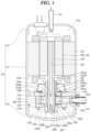
- FIG. 1 is a cross-sectional view illustrating one implementation of a vane rotary compressor according to the present disclosure
- FIG. 2 is an exploded perspective view illustrating a compression part in FIG. 1
- FIG. 3 is an assembled planar view of the compression part in FIG. 2 .
- a vane rotary compressor includes a casing 110, a driving (or drive) motor 120, and a compression part 130.
- the driving motor 120 is installed in an upper inner space 110a of the casing 110
- the compression part 130 is installed in a lower inner space 110a of the casing 110.
- the driving motor 120 and the compression part 130 are connected through a rotating shaft 123.
- the casing 110 that defines an outer appearance of the compressor may be classified as a vertical type and a horizontal type according to a compressor installation method.
- the driving motor 120 and the compression part 130 are disposed at upper and lower sides in an axial direction, respectively.
- the driving motor 120 and the compression part 130 are disposed at left and right sides, respectively.
- the casing according to this implementation may be illustrated as the vertical type.
- the casing 110 includes an intermediate shell 111 having a cylindrical shape, a lower shell 112 covering a lower end of the intermediate shell 111, and an upper shell 113 covering an upper end of the intermediate shell 111.
- the driving motor 120 and the compression part 130 may be inserted into the intermediate shell 111 to be fixed thereto, and a suction pipe 115 may penetrate through the intermediate shell 111 to be directly connected to the compression part 130.
- the lower shell 112 may be coupled to the lower end of the intermediate shell 111 in a sealing manner, and an oil storage space 110b in which oil to be supplied to the compression part 130 is stored may be formed below the compression part 130.
- the upper shell 113 may be coupled to the upper end of the intermediate shell 111 in a sealing manner, and an oil separation space 110c may be formed above the driving motor 120 to separate oil from refrigerant discharged from the compression part 130.
- the driving motor 120 that constitutes a motor part supplies power to cause the compression part 130 to be driven.
- the driving motor 120 includes a stator 121, a rotor 122, and a rotating shaft 123.
- the stator 121 may be fixedly inserted into the casing 110.
- the stator 121 may be fixed to an inner circumferential surface of the casing 110 in a shrink-fitting manner or the like.
- the stator 121 may be press-fitted into an inner circumferential surface of the intermediate shell 111.
- the rotor 122 may be rotatably inserted into the stator 121, and the rotating shaft 123 may be press-fitted into a center of the rotor 122. Accordingly, the rotating shaft 123 rotates concentrically together with the rotor 122.
- An oil flow path 125 having a hollow hole shape is formed in a central portion of the rotating shaft 123, and oil passage holes 126a and 126b are formed through a middle portion of the oil flow path 125 toward an outer circumferential surface of the rotating shaft 123.
- the oil passage holes 126a and 126b include a first oil passage hole 126a belonging to a range of a main bush portion 1312 to be described later and a second oil passage hole 126b belonging to a range of a sub bush portion 1322.
- Each of the first oil passage hole 126a and the second oil passage hole 126b may be provided by one or in plurality. In this implementation, each of the first and second oil passage holes is provided in plurality.
- An oil pickup 127 may be installed at a middle or lower end of the oil flow path 125.
- a gear pump, a viscous pump, or a centrifugal pump may be used for the oil pickup 127.
- This implementation illustrates a case in which the centrifugal pump is employed. Accordingly, when the rotating shaft 123 rotates, oil filled in the oil storage space 110b is pumped by the oil pickup 127 and is sucked along the oil flow path 125, so as to be introduced into a sub bearing surface 1322b of the sub bush portion 1322 through the second oil passage hole 126b and into a main bearing surface 1312b of the main bush portion 1312 through the first oil passage hole 126a.
- the rotating shaft 123 may include a roller 134 to be described later.
- the roller 134 may extend integrally from the rotating shaft 123 or the rotating shaft 123 and the roller 134 that are separately manufactured may be post-assembled to each other.
- the rotating shaft 123 is post-assembled by being inserted into the roller 134.
- a shaft hole 1341 may be formed through a center of the roller 134 in an axial direction and the rotating shaft 123 may be press-fitted into the shaft hole 1341 or coupled to the shaft hole 1341 to be movable in the axial direction.
- a rotation preventing unit (not illustrated) may be provided between the rotating shaft 123 and the roller 134 so that the rotating shaft 123 can be locked with respect to the roller 134 in the circumferential direction.
- the compression part 130 includes a main bearing 131, a sub bearing 132, a cylinder 133, a roller 134, and a plurality of vanes 1351, 1352, and 1353.
- the main bearing 131 and the sub bearing 132 are respectively provided at upper and lower parts of the cylinder 133 to define a compression space V together with the cylinder 133, the roller 134 is rotatably installed in the compression space V, and the vanes 1351, 1352, and 1353 are slidably inserted into the roller 134 to divide the compression space V into a plurality of compression chambers.
- the main bearing 131 may be fixedly installed in the intermediate shell 111 of the casing 110.
- the main bearing 131 may be inserted into the intermediate shell 111 and welded thereto.
- the main bearing 131 may be coupled to an upper end of the cylinder 133 in a close contact manner. Accordingly, the main bearing 131 defines an upper surface of the compression space V, and supports an upper surface of the roller 134 in the axial direction and at the same time supports an upper portion of the rotating shaft 123 in the radial direction.
- the main bearing 131 may include a main plate portion 1311 and a main bush portion 1322.
- the main plate portion 1311 covers an upper part of the cylinder 133 to be coupled thereto, and the main bush portion 1312 axially extends from a center of the main plate portion 1311 toward the driving motor 120 so as to support the upper portion of the rotating shaft 123.
- the main plate portion 1311 may have a disk shape, and an outer circumferential surface of the main plate portion 1311 may be fixed to the inner circumferential surface of the intermediate shell 111 in a close contact manner.
- One or more discharge ports 1313a, 1313b, and 1313c may be formed in the main plate portion 1311, and a plurality of discharge valves 1361, 1362, and 1363 configured to open and close the respective discharge ports 1313a, 1313b, and 1313c may be installed on an upper surface of the main plate portion 1311, and a discharge muffler 137 having a discharge space (no reference numeral) may be provided at an upper part of the main plate portion 1311 to accommodate the discharge ports 1313a, 1313b, and 1313c, and the discharge valves 1361, 1362, and 1363.
- the discharge ports 1313a, 1313b, and 1313c may be formed in the main bearing (or sub bearing) 131, instead of the cylinder 133, which can simplify the structure of the cylinder 133 so as to facilitate processing of the cylinder 133.
- surface pressure between the front surface of the vane 133 in the vicinity of the discharge port 1313a, 1313b, 1313c and the inner circumferential surface of the cylinder 131 facing it can be lowered and constantly maintained at the same time, while chattering of the vane 1351, 1352, 1353 can be reduced so as to suppress wear and vibration noise between the front surface of the vane 1351, 1352, 1353 and the inner circumferential surface of the cylinder 133 facing it.
- the discharge ports will be described again later.
- a first main back pressure pocket 1315a and a second main back pressure pocket 1315b may be formed in a lower surface, namely, a main sliding surface 1311a of the main plate portion 1311 facing the upper surface of the roller 134, of both axial side surfaces of the main plate portion 1311.
- the first main back pressure pocket 1315a and the second main back pressure pocket 1315b each having an arcuate shape may be disposed at a predetermined interval in a circumferential direction.
- Each of the first main back pressure pocket 1315a and the second main back pressure pocket 1315b may have an inner circumferential surface with a circular shape, but may have an outer circumferential surface with an oval or elliptical shape in consideration of vane slots to be described later.
- the first main back pressure pocket 1315a and the second main back pressure pocket 1315b may be formed within an outer diameter range of the roller 134. Accordingly, the first main back pressure pocket 1315a and the second main back pressure pocket 1315b may be separated from the compression space V. However, the first main back pressure pocket 1315a and the second main back pressure pocket 1315b may slightly communicate with each other through a gap between a lower surface, a main sliding surface 1311a of the main plate portion 1311 and the upper surface of the roller 134 facing each other unless a separate sealing member is provided therebetween.
- the first main back pressure pocket 1315a forms pressure lower than pressure formed in the second main back pressure pocket 1315b, for example, forms intermediate pressure between suction pressure and discharge pressure.
- Oil refrigerant oil
- the first main back pressure pocket 1315a may be formed in the range of a compression chamber forming intermediate pressure in the compression space V. This may allow the first main back pressure pocket 1315a to maintain the intermediate pressure.
- the second main back pressure pocket 1315b may form pressure higher than that in the first main back pressure pocket 1315a, for example, discharge pressure or intermediate pressure between suction pressure close to the discharge pressure and the discharge pressure. Oil flowing into the main bearing hole 1312a of the main bearing 1312 through the first oil passage hole 126a may be introduced into the second main back pressure pocket 1315b.
- the second main back pressure pocket 1315b may be formed in the range of a compression chamber forming a discharge pressure in the compression space V. This may allow the second main back pressure pocket 1315b to maintain the discharge pressure.
- a first main bearing protrusion 1316a and a second main bearing protrusion 1316b may be formed on inner circumferential sides of the first main back pressure pocket 1315a and the second main back pressure pocket 1315b, respectively, in a manner of extending from the main bearing surface 1312b of the main bush potion 1312. Accordingly, the first main back pressure pocket 1315a and the second main back pressure pocket 1315b can be sealed from outside and simultaneously the rotating shaft 123 can be stably supported.
- the first main bearing protrusion 1316a and the second main bearing protrusion 1316b may have the same height or different heights.
- an oil communication groove (not illustrated) or an oil communication hole (not illustrated) may be formed on an end surface of the second main bearing protrusion 1316b such that inner and outer circumferential surfaces of the second main bearing protrusion 1316b can communicate with each other. Accordingly, high-pressure oil (refrigerant oil) flowing into the main bearing surface 1312b can be introduced into the second main back pressure pocket 1315b through the oil communication groove (not illustrated) or the oil communication hole (not illustrated).
- the height of the second main bearing protrusion 1316b may be lower than the height of the first main bearing protrusion 1316a. Accordingly, high-pressure oil (refrigerant oil) flowing into the main bearing hole 1312a can be introduced into the second main back pressure pocket 1315b by passing over the second main bearing protrusion 1316b.
- a third outflow guide portion 143 defining a part of a residual refrigerant outflow passage 140 to be described later may be formed on the main sliding surface 1311a.
- the third outflow guide portion 143 may be formed between the first main back pressure pocket 1315a and the second main back pressure pocket 1315b.
- a first end 143a of the third outflow guide portion 143 may be formed to periodically communicate with a second end 142b of a second outflow guide portion 142 of the roller 134 to be described later, and a second end 143b of the third outflow guide portion 143 may be formed through the main bush portion 1312 to be described later in the axial direction to be open toward the inner space 110a of the casing 110.
- the third outflow guide portion 143 will be described again later along with the residual refrigerant outflow passage 140.
- the main bush portion 1312 may be formed in a hollow bush shape, and a first oil groove 1312c may be formed in an inner circumferential surface of the main bearing hole 1312a that defines an inner circumferential surface of the main bush portion 1312.
- the first oil groove 1312c may be formed in a straight or inclined shape between upper and lower ends of the main bush portion 1312 to communicate with the first oil passage hole 126a.
- the sub bearing 132 may be coupled to a lower end of the cylinder 133 in a close contact manner. Accordingly, the sub bearing 132 defines a lower surface of the compression space V, and supports a lower surface of the roller 134 in the axial direction and at the same time supports a lower portion of the rotating shaft 123 in the radial direction.
- the sub bearing 132 may include a sub plate potion 1321 and the sub bush portion 1322.
- the sub plate portion 1321 may cover a lower part of the cylinder 133 to be coupled to thereto, and the sub bush portion 1322 may axially extend from a center of the sub plate portion 1321 toward the lower shell 112 so as to support the lower portion of the rotating shaft 123.
- the sub plate portion 1321 may have a disk shape like the main plate portion 1311, and an outer circumferential surface of the sub plate portion 1321 may be spaced apart from the inner circumferential surface of the intermediate shell 111.
- a first sub back pressure pocket 1325a and a second sub back pressure pocket 1325b may be formed on an upper surface, namely, a sub sliding surface 1321a of the sub plate portion 1321 facing the lower surface of the roller 134, of both axial side surfaces of the sub plate portion 1321.
- the first sub back pressure pocket 1325a and the second sub back pressure pocket 1325b may be symmetric to the first main back pressure pocket 1315a and the second main back pressure pocket 1315b, respectively, with respect to the roller 134.
- first sub back pressure pocket 1325a and the first main back pressure pocket 1315a may be symmetric to each other, and the second sub back pressure pocket 1325b and the second main back pressure pocket 1315b may be symmetric to each other.
- a first sub bearing protrusion 1326a may be formed on an inner circumferential side of the first sub back pressure pocket 1325a
- a second sub bearing protrusion 1326b may be formed on an inner circumferential side of the second sub back pressure pocket 1325b.
- first sub back pressure pocket 1325a and the second sub back pressure pocket 1325b may be asymmetric to the first main back pressure pocket 1315a and the second main back pressure pocket 1315b, respectively, with respect to the roller 134.
- first sub back pressure pocket 1325a and the second sub back pressure pocket 1325b may be formed to be deeper than the first main back pressure pocket 1315a and the second main back pressure pocket 1315b, respectively.
- a first outflow guide portion 141 defining a part of a residual refrigerant outflow passage 140 to be described later may be formed on the sub sliding surface 1321a.
- the first outflow guide portion 141 may be formed between the first sub back pressure pocket 1325a and the second sub back pressure pocket 1325b.
- One side of the first outflow guide portion 141 may communicate with the compression space V, more precisely, a residual space S, and another side of the first outflow guide portion 141 may periodically communicate with the second outflow guide portion 142 to be described later, which is disposed in the roller 134.
- the first outflow guide portion 141 will be described again later along with the residual refrigerant outflow passage 140.
- the sub bush portion 1322 may be formed in a hollow bush shape, and an oil groove (not illustrated) may be formed in an inner circumferential surface of the sub bearing hole 1322a that defines an inner circumferential surface of the sub bush portion 1322.
- the oil groove (not illustrated) may be formed in a straight or inclined shape between upper and lower ends of the sub bush portion 1322 to communicate with the second oil passage hole 126b.
- the back pressure pockets 1315a, 1315b, 1325a, 1325b may be provided only at any one of the main bearing 131 and the sub bearing 132.
- the discharge port 1313 may be formed in the main bearing 131 as described above.
- the discharge port 1313 may be formed in the sub bearing 132, formed in each of the main bearing 131 and the sub bearing 132, or formed by penetrating between inner and outer circumferential surfaces of the cylinder 133. This implementation describes an example in which the discharge ports 1313 are formed in the main bearing 131.
- the discharge port 1313 may be provided by one. However, in this implementation, the plurality of discharge ports 1313a, 1313b, and 1313c may be formed at predetermined intervals along a compression proceeding direction (or a rotational direction of the roller).
- a contact point P at which the roller 134 and the cylinder 133 almost come in contact with each other is generated between an outer circumferential surface 1342 of the roller 134 and an inner circumferential surface 1332 of the cylinder 133.
- the discharge port 1313 is formed adjacent to the contact point P at an opposite side of the suction port 1331 with respect to the contact point P. Accordingly, as the compression space V approaches the contact point P, the distance between the inner circumferential surface 1332 of the cylinder 133 and the outer circumferential surface 1342 of the roller 134 is greatly decreased, which makes it difficult to secure an area of the discharge port 1313.
- the discharge port 1313 may be divided into a plurality of discharge ports 1313a, 1313b, and 1313c each having a small inner diameter, and the plurality of discharge ports 1313a, 1313b, 1313c may be disposed at preset intervals along a circumferential direction, namely, a rotational direction of the roller 134.
- the plurality of discharge ports 1313a, 1313b, and 1313c may be formed individually, but may be formed as pairs, as illustrated in this implementation. For example, starting from a discharge port which is the most adjacent to the proximal portion 1332a, the first discharge port 1313a, the second discharge port 1313b, and the third discharge port 1313c of the discharge port 1313 may be sequentially arranged.
- a distance between the adjacent discharge ports 1313a, 1313b, and 1313c may be formed to be substantially the same.
- a first distance between the rear end of the first discharge port 1313a and the front end of the second discharge port 1313b may be substantially the same as a second distance between the rear end of the second discharge port 1313b and the front end of the third discharge port 1313c.
- a distance from the front end to the rear end of the discharge port 1313 may be substantially the same as an arcuate length of each compression chamber V1, V2, V3.
- the arcuate length between the front end of the first discharge port 1313a and the rear end of the third discharge port 1313b may be approximately similar to a distance between a preceding vane and a succeeding vane, namely, the arcuate length of each compression chamber V1, V2, V3.
- the arcuate length between the front end of the first discharge port 1313a and the rear end of the third discharge port 1313b may be greater than the distance between a preceding vane and a succeeding vane, namely, the arcuate length of each compression chamber V1, V2, V3.
- continuous discharge can be allowed as at least one compression chamber V1, V2, V3 is located within a circumferential range of the discharge port 1313, which can suppress over-compression and/or pressure pulsation.
- each compression chamber V1, V2, V3 may be different, and the plurality of discharge ports may communicate with one compression chamber or one discharge port may communicate with the plurality of compression chambers.
- the plurality of discharge ports 1313a, 1313b, and 1313c may be opened and closed by the discharge valves 1361, 1362, and 1363, respectively.
- Each of the discharge valves 1361, 1362, and 1363 may be implemented as a cantilever type reed valve having one end fixed and another end free.
- These discharge valves 1361, 1362, and 1362 are widely known in the conventional rotary compressor, so a detailed description thereof will be omitted.
- the cylinder 133 may be in close contact with a lower surface of the main bearing 131 and be coupled to the main bearing 131 by a bolt together with the sub bearing 132. Accordingly, the cylinder 133 may be fixedly coupled to the casing 110 by the main bearing 131.
- the cylinder 133 may be formed in an annular shape having a hollow space in its center to define the compression space V.
- the hollow space may be sealed by the main bearing 131 and the sub bearing 132 to define the compression space V, and the roller 134 to be described later may be rotatably coupled to the compression space V.
- the cylinder 133 may be provided with a suction port 1331 penetrating from an outer circumferential surface to an inner circumferential surface thereof.
- the suction port may alternatively be formed through the main bearing 131 or the sub bearing 132.
- the suction port 1331 may be formed at one side of the contact point P in the circumferential direction.
- the discharge port 1313 described above may be formed through the main bearing 131 at another side of the contact point P in the circumferential direction that is opposite to the suction port 1331.
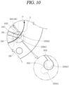
- the inner circumferential surface 1332 of the cylinder 133 may be formed in an elliptical shape.
- the inner circumferential surface 1332 of the cylinder 133 according to this implementation may be formed in an asymmetric elliptical shape in which a plurality of ellipses, for example, four ellipses having different major and minor ratios are combined to have two origins.
- An X-Y plane formed around the first origin O may define a third quadrant Q3 and a fourth quadrant Q4, and an X-Y plane formed around the second origin O' may define a first quadrant Q1 and a second quadrant Q2.
- the third quadrant Q3 may be formed by a third ellipse
- the fourth quadrant Q4 may be formed by a fourth ellipse
- the first quadrant Q1 may be formed by the first ellipse
- the second quadrant Q2 may be formed by the second ellipse.
- the proximal portion 1332a may also be defined as the contact point P, and the first quadrant Q1 and the fourth quadrant Q4 may be divided based on the proximal portion 1332a.
- the suction port 1331 may be formed in the first quadrant Q1 and the discharge port 1313 may be formed in the fourth quadrant Q4, based on the proximal portion 1332a. Accordingly, when the vane 1351, 1352, 1353 passes the contact point P, a compression surface of the roller 134 in the rotational direction may receive suction pressure as low pressure but an opposite compression rear surface may receive discharge pressure as high pressure.
- the roller 134 may extend integrally from the rotating shaft 123 or may be manufactured separately from the rotating shaft 123 and then post-assembled to the rotating shaft 123. This implementation will be described based on an example in which the roller is post-assembled to the rotating shaft 123.
- the roller 134 may be formed as a single body, that is, an integral roller having one roller body (no reference numeral). However, the roller 134 may not be necessarily formed as the integral roller. For example, the roller 134 may be formed as a separable roller that is separated into a plurality of roller bodies (no reference numeral). This will be described later in another implementation. In this implementation, an integral roller 134 configured as a single body will be described as an example.
- the roller 134 may be formed in an annular shape with a shaft hole 1341 at the center thereof.
- the roller 134 may have inner and outer circumferential surfaces, and the inner and outer circumferential surfaces of the roller 134 may be formed in a circular shape.
- the inner circumferential surface of the roller 134 may be formed as a continuous seamless surface, whereas the outer circumferential surface of the roller 134 may be formed by discontinuous surfaces which are as many as the number of vane slots 1343a because of open surfaces of the vane slots 1343a, 1343b, 1343c, which will be described later.
- the rotation center Or of the roller 134 is coaxially located with an axial center (no reference numeral) of the rotating shaft 123, and the roller 134 rotates concentrically with the rotating shaft 123.
- the rotation center Or of the roller 134 may be eccentrically disposed with respect to an outer diameter center Oc of the cylinder 133. Accordingly, one side of the outer circumferential surface 1341b of the roller 134 may be substantially brought into contact with the inner circumferential surface 1332 of the cylinder 133, precisely, the proximal portion 1332a, thereby defining the contact point P.
- each of the vane slots 1343a, 1343b, and 1343c may be inclined by a preset angle with respect to the radial direction, so as to secure a sufficient length of each of the vanes 1351, 1352, and 1353. Accordingly, when the inner circumferential surface 1332 of the cylinder 133 is formed in the asymmetric elliptical shape, even if a distance from the outer circumferential surface 1342 of the roller 134 to the inner circumferential surface 1332 of the cylinder 133 increases, the separation of the vanes 1351, 1352, and 1353 from the vane slots 1343a, 1343b, and 1343c can be suppressed, which may result in enhancing the design freedom for the inner circumferential surface 1332 of the cylinder 133 as well as that of the roller 134.
- the back pressure chambers 1344a, 1344b, and 1344c may be formed to communicate with the inner ends of the vane slots 1343a, 1343b, and 1343c, respectively.
- the back pressure chambers 1344a, 1344b, and 1344c may be spaces in which oil (or refrigerant) of discharge pressure or intermediate pressure is filled to flow toward the rear sides of the vanes 1351, 1352, and 1353, that is, the rear end surfaces 1351c, 1352c, and 1353c of the vanes 1351, 1352, 1353.
- the vanes 1351, 1352, and 1353 may be pressed toward the inner circumferential surface of the cylinder 133 by the pressure of the oil (or refrigerant) filled in the back pressure chambers 1344a, 1344b, and 1344c.
- a direction toward the inner circumferential surface of the cylinder based on a motion direction of the vane may be defined as the front, and an opposite side to the direction may be defined as the rear.
- the plurality of vane slots 1343a, 1343b, and 1343c may be formed in the radial direction, that is, radially with respect to the rotation center Or of the roller 134.
- Operating effects to be obtained by the configuration are similar to those in the following implementation in which the plurality of vane slots 1343a, 1343b, and 1343c are inclined with respect to the rotation center Or of the roller 134, which will be described later, so a description thereof will be replaced with a description of the implementation to be given later.
- a second outflow guide portion 142 defining a part of a residual refrigerant outflow passage 140 to be described later may be formed in the roller 134.
- the second outflow guide portion 142 may be provided in plurality disposed between the vane slots [(1343a, 1343b), (1343b, 1343c), (1343c, 1343a)] adjacent to each other in the circumferential direction, respectively.
- a first end 142a of the second outflow guide portion 142 may periodically communicate with a second end 1412b of a second guide groove 1412 of the first outflow guide portion 1412, and a second end 142b of the second outflow guide portion 142 may periodically communicate with a first end 143a of the third outflow guide portion 143 to be described later.
- the second outflow guide portion 142 will be described again later along with the residual refrigerant outflow passage 140.
- the back pressure chamber 1342a, 1342b, 1342c may be hermetically sealed by the main bearing 131 and the sub bearing 132.
- the back pressure chambers 1344a, 1344b, and 1344c may independently communicate with each of the back pressure pockets [1315a, 1315b], [1325a, 1325b], and may also communicate with each other through the back pressure pockets [1315a, 1315b], [1325a, 1325b].
- a plurality of vanes 1351, 1352, and 1353 may be slidably inserted into the respective vane slots 1343a, 1343b, and 1343c. Accordingly, the plurality of vanes 1351, 1352, and 1353 may have substantially the same shape as the respective vane slots 1343a, 1343b, and 1343c.
- the plurality of vanes 1351, 1352, 1353 may be defined as a first vane 1351, a second vane 1352, and a third vane 1353 along the rotational direction of the roller 134.
- the first vane 1351 may be inserted into the first vane slot 1343a, the second vane 1352 into the second vane slot 1343b, and the third vane 1353 into the third vane slot 1343c, respectively.
- the plurality of vanes 1351, 1352, and 1353 may have substantially the same shape.
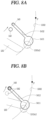
- the plurality of vanes 1351, 1352, and 1353 may each be formed in a substantially rectangular parallelepiped shape, and the front surfaces 1351a, 1352a, 1353a of the vanes 1351, 1352, and 1353 in contact with the inner circumferential surface 1332 of the cylinder 133 may be curved in the circumferential direction. Accordingly, the front surfaces 1351a, 1352a, and 1353a of the vanes 1351, 1352, and 1353 can come into line-contact with the inner circumferential surface 1332 of the cylinder 133, thereby reducing friction loss.
- the sub bearing 132, the roller 134, and the main bearing 131 may communicate with a residual space S, thereby defining a residual refrigerant outflow passage 140 through which refrigerant remaining in the residual space S can flow to the inner space 110a of the casing 110.
- the residual refrigerant outflow passage 140 may include the first outflow guide portion 141 disposed in the sub bearing 132, the second outflow guide portion 142 disposed in the roller 134, and the third outflow guide portion 143 disposed in the main bearing 131.
- the first outflow guide portion 141, the second outflow guide portion 142, and the third outflow guide portion 143 may be formed to communicate with one another in a sequential manner. Accordingly, the refrigerant remaining in the residual space S can flow into the inner space 110a of the casing 110 sequentially through the first outflow guide portion 141, the second outflow guide portion 142, and the third outflow guide portion 143.
- the residual refrigerant outflow passage 140 will be described again later.
- the plurality of vanes 1351, 1352, and 1353 may be drawn out of the vane slots 1343a, 1343b, and 1343c by centrifugal force generated by the rotation of the roller 134 and back pressure of the back pressure chambers 1344a, 1344b, and 1344c, which support the rear end surfaces 1351b, 1353b, 1353b of the vanes 1351, 1352, and 1353, thereby being brought into contact with the inner circumferential surface 1332 of the cylinder 133.
- the compression space V of the cylinder 133 may be partitioned by the plurality of vanes 1351, 1352, and 1353 into as many compression chambers (including suction chamber or discharge chamber) V1, V2, and V3 as the number of the vanes 1351, 1352, and 1353.
- the compression chambers V1, V2, and V3 may be changed in volume by the shape of the inner circumferential surface 1332 of the cylinder 133 and eccentricity of the roller 134 while moving in response to the rotation of the roller 134. Accordingly, refrigerant suctioned into the respective compression chambers V1, V2, and V3 can be compressed while moving along the roller 134 and the vanes 1351, 1352, and 1353, and discharged into the inner space of the casing 110. Such series of processes may be repeatedly carried out.
- the third discharge port 1313c which is the final discharge port, is located at a predetermined distance from the contact point P in the circumferential direction. Accordingly, the residual space S is defined between the third discharge port 1313c and the contact point P, and refrigerant which has not been discharged even through the third discharge port 1313c remains in the residual space S. This may cause over-compression in the residual space S as described above, thereby reducing compressor efficiency.
- a residual refrigerant outflow passage (hereinafter, outflow passage) 140 that has one end communicating with a portion between the third discharge port 1313c and the contact point P, and another end communicating with the inner space 110a of the casing 110. Accordingly, the refrigerant remaining in the residual space S can flow into the inner space 110a of the casing 110 through the outflow passage 140, to thus suppress or minimize the refrigerant remaining in the residual space S, thereby preventing the compressor efficiency from being lowered due to over-compression of the refrigerant.
- the outflow passage 140 may include an inlet formed in a bearing in which any discharge port is not formed, and an outlet formed in a bearing having a discharge port with the roller 134 interposed therebetween.
- the roller 134 may have an intermediate passage through which the inlet and the outlet of the outflow passage 140 communicate with each other periodically or intermittently. Accordingly, the refrigerant remaining in the residual space S can flow into the inner space 110a of the casing 110 sequentially through the inlet of the outflow passage 140, the intermediate passage of the outflow passage 140, and the outlet of the outflow passage 140 when the inlet and the outlet of the outflow passage 140 communicate with each other through the intermediate passage.
- the inlet of the outflow passage 140 may be formed in the sub bearing 132 and the outlet of the outflow passage 140 may be formed in the main bearing 131.
- the inlet of the outflow passage 140 may be formed in the main bearing 131 and the outlet of the outflow passage 140 may be formed in the sub bearing 132.
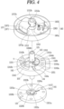
- FIG. 4 is a perspective view illustrating an outflow passage by exploding the compression part in FIG. 1
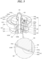
- FIG. 5 is a perspective view illustrating the outflow passage by exploding the assembled compression part in FIG. 4
- FIG. 6 is a cross-sectional view of the outflow passage in FIG. 5
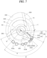
- FIG. 7 is a schematic view illustrating a position of a first outflow guide portion in the vane rotary compressor according to FIG. 1 .
- the discharge ports 1313a, 1313b, 1313c may be formed through the main plate portion 1311 of the main bearing 131 in the axial direction, discharge valves 1361, 1362, and 1363 for opening and closing the discharge ports 1313a, 1313b, and 1313c may be disposed on one surface of the main plate portion 1311, namely, on an opposite surface to the main sliding surface 1311a, and a discharge muffler 137 in which the discharge ports 1313a, 1313b, and 1313c and the discharge valves 1361, 1362, and 1363 are accommodated may be disposed on an outer surface of the main bearing 131.
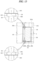
- the discharge muffler 137 may include a muffler fixing portion 1371 and a discharge space portion 1372.
- the muffler fixing portion 1371 may be formed in a flange shape to be fastened to the outer surface of the main bearing 131, and the discharge space portion 1372 may be formed in a substantially cylindrical shape by extending from an inner circumferential surface of the muffler fixing portion 1371.
- the muffler fixing portion 1371 may have an outer diameter smaller than an outer diameter of the main plate portion 1311, and include a plurality of bolt holes (no reference numerals) formed in the circumferential direction, such that the discharge muffler 137 can be coupled to the main bearing 131 together with the cylinder 133 and the sub bearing 132 by bolts.
- the discharge space portion 1372 may be bent from the muffler fixing portion 1371 and protrude in the axial direction to have a substantially cylindrical shape. Accordingly, an inner surface of the discharge space portion 1372 may be spaced apart from an outer surface of the main plate portion 1311 to define a discharge space 1372a.
- the discharge ports 1313a, 1313b, and 1313c and the discharge valves 1361, 1362, and 1363 can be accommodated in the discharge space 1372a.
- a height H1 of the discharge space portion 1372 based on an upper surface of the main plate 1311 may be lower than a height H2 of the main bush portion 1312, and a bearing through hole 1372b may be formed through a center of the discharge space portion 1372. Accordingly, the discharge space portion 1372 can be engaged with the main bush portion 1312 of the main bearing 131.
- An inner circumferential surface of the bearing through hole 1372b may be spaced apart from the outer circumferential surface of the main bush portion 1312 by a preset distance, thereby defining an outflow gap D between the inner circumferential surface of the bearing through hole 1372b and the outer circumferential surface of the main bush portion 1312. Accordingly, refrigerant compressed in the compression chambers V1, V2, and V3 is discharged into the discharge space 1372a of the discharge muffler 137 through the discharge ports 1313a, 1313b, and 1313c. The refrigerant then flows into the discharge space 110a of the casing 110 through the outflow gap D between the inner circumferential surface of the discharge muffler 137 and the outer circumferential surface of the main bush portion 1312. At this time, a pressure pulsation of the refrigerant can be reduced in the discharge space 1372a.
- the outflow passage 140 may include a first outflow guide portion 141, a second outflow guide portion 142, and a third outflow guide portion 143.
- the first outflow guide portion 141 may be formed in the sub bearing 132
- the second outflow guide portion 142 may be formed in the roller 134
- the third outflow guide portion 143 may be formed in the main bearing 131, respectively.
- the first outflow guide portion 141 may include a first guide groove 1411 and a second guide groove 1412.
- the first guide groove 1411 may communicate with the compression space V, more precisely, the residual space S, and the second guide groove 1412 may communicate with the second outflow guide portion 142.
- the first guide groove 1411 may have substantially the same shape as the third discharge port 1313c that is the final discharge port.
- the first guide groove 1411 may be formed to have a circular cross-section.
- the first guide groove 1411 may be formed at a position where at least a portion thereof overlaps the third discharge port 1313c in the axial direction.
- the first guide groove 1411 may be located at a position where at least a portion thereof overlaps a third discharge port (hereinafter, a rear-side third discharge port) 1313c2 which is relatively adjacent to the contact point.
- the first guide groove 1411 may be formed to be located on the same axis as the rear-side third discharge port 1313c2 or to be more adjacent to the contact point P than the rear-side third discharge port 1313c2.
- the first guide groove 1411 may be more eccentric toward the contact point P than the rear-side third discharge port 1313c2.
- the first guide groove 1411 is formed at a position more than about 5° apart from the contact point P so as to secure the minimum sealing distance ⁇ . This can suppress high-pressure refrigerant from flowing into a suction side beyond the contact point P due to the first guide groove 1411.
- the first guide groove 1411 may be located on the same axis as the rear-side third discharge port 1313c2. Even in this case, the high-pressure refrigerant can be suppressed from flowing into a suction side beyond the contact point P due to the first guide groove 1411.
- first guide groove 1411 may be formed to overlap the rear-side third discharge port 1313c2 in the axial direction by about 50% or more of a total area of the first guide groove 1411. Accordingly, an area where the first guide groove 1411 overlaps the aforementioned residual space S in the axial direction can increase, so that the residual refrigerant can effectively flow out.
- a discharge passage arcuate angle ⁇ may be larger than or equal to an angle ⁇ between vanes, and preferably, may be larger than the angle ⁇ between the vanes.
- FIG. 7 illustrates that the discharge passage arcuate angle ⁇ is smaller than the angle ⁇ between the vanes.
- the discharge passage arcuate angle ⁇ may be larger than or equal to the angle ⁇ between the vanes.
- the discharge passage arcuate angle ⁇ may be defined as an arcuate angle between a start end of the first discharge port 1313a which is the first discharge port and an end of the first guide groove 1411 located beyond the third discharge port 1313c which is the final discharge port
- the angle ⁇ between the vanes may be defined as an arcuate angle between neighboring vanes (i.e., (1351 and 1352) (1352 and 1353), and (1353c and 1351) when the three vanes 1351, 1352, and 1353 are disposed at equal intervals in the circumferential direction of the roller 134.
- the angle ⁇ between the vanes may be 120°, and the discharge passage arcuate angle ⁇ may be approximately larger than or equal to 120°, preferably, larger than 120°.
- the discharge passage including the discharge port and the outflow passage 140 may extend to a circumferential range of a corresponding compression chamber or to outside of the circumferential range of the compression chamber. Then, a length of a discharge stroke for refrigerant in the compression chamber can be secured longer than a length of a compression stroke, which may result in minimizing an amount of compressed refrigerant which remains in the compression chamber after the discharge stroke or in the residual space S adjacent to the contact point P.
- an arcuate length of the discharge passage is longer than or equal to an arcuate length of the compression chamber, a continuous discharge can be achieved, thereby reducing a pressure pulsation.
- the first guide groove 1411 may have a cross-sectional area that is greater than or equal to that of the rear-side third discharge port 1313c2. This can increase an area of the first guide groove 1411 that overlaps the residual refrigerant, so that the residual refrigerant can be more effectively exhausted.
- the first guide groove 1411 may have a cross-sectional area that is smaller than that of the rear-side third discharge port 1313c2.
- the first guide groove 1411 may be formed in various shapes. For example, in FIGS. 4 to 8 , only one first guide groove 1411 is formed, but in some cases, two first guide groove 1411 may be provided as a pair, like the third discharge ports, to communicate with each other or to be formed in the form of a single long groove. In this case, the first guide groove 1411 can be elongated in the circumferential direction such that the residual refrigerant can be more effectively exhausted.
- a first end 1412a of the second guide groove 1412 may communicate with the first guide groove 1411, and a second end 1412b of the second guide groove 1412 may communicate with the second outflow guide portion 142.
- the second guide groove 1412 may be formed in a rectangular shape extending long in the radial direction.
- first end 1412a of the second guide groove 1412 may be located radially outward, and the second end 1412b of the second guide groove 1412 may be located radially inward. Accordingly, the second end 1412b of the second guide groove 1412 may be located closer to the rotation center Or of the roller 134 than the first guide groove 1411.
- a cross-sectional area (or width) of the second guide groove 1412 may be smaller than an inner diameter of the first guide groove 1411.
- the second guide groove 1412 may be thinner and longer than the first guide groove 1411. Accordingly, a portion of the second guide groove 1412 can be located between the first sub back pressure pocket 1325a and the second sub back pressure pocket 1325b.
- the first end 1412a of the second guide groove 1412 may be located outside a pocket virtual circle C connecting the outer circumferential surface of the first sub back pressure pocket 1325a and the outer circumferential surface of the second sub back pressure pocket 1325b.
- the second end 1412b of the second guide groove 1412 may be located between the first sub back pressure pocket 1325a and the second sub back pressure pocket 1325b in the circumferential direction.
- the second guide groove 1412 may have a cross-sectional area that is greater than or equal to a cross-sectional area of the second outflow guide portion 142 on the same axis as the second outflow guide portion 142 to be described later. Accordingly, the second guide groove 1412 can periodically communicate with the second outflow guide portion 142 provided in the roller 134 when the roller 134 rotates.
- the second outflow guide portion 142 may be formed through both axial side surfaces of the roller 134.
- the first end 142a of the second outflow guide portion 142 may be open to a lower surface of the roller 134 facing the sub-sliding surface 1321a
- the second end 142b of the second outflow guide portion 142 may be open to an upper surface of the roller 134 facing the main bearing surface 131.
- the second outflow guide portion 142 may be formed through the roller 134 in the axial direction. Accordingly, the second outflow guide portion 142 can be easily processed. However, the second outflow guide portion 142 does not necessarily have to be formed through the roller 134 in the axial direction.
- the second outflow guide portion 142 may be inclined with respect to the axial direction, for example, may be inclined in a forward direction with respect to the rotational direction of the roller 134 from the first end 142a to the second end 142b of the second outflow guide portion 142.
- the refrigerant of the first outflow guide portion 141 can flow out more rapidly by receiving centrifugal force while passing through the second outflow guide portion 142.
- the second outflow guide portion 142 may be located at a position where it overlaps the second guide groove 1412 of the first outflow guide portion 141 in the axial direction. Accordingly, when the roller 134 rotates, the second outflow guide portion 142 can periodically communicate with the second guide groove 1412 of the first outflow guide portion 141.
- the second outflow guide portion 142 may be one or more in number.
- the number of the second outflow guide portions 142 may be greater than the number of the first outflow guide portions 141, more precisely, the number of the second guide grooves 1412. Accordingly, the second outflow guide portion 142 may communicate with the second guide groove 1412 per rotation of the roller 134 plural times, to be precise, as many times as the number of the second outflow guide portions 142.
- the first outflow guide portion 141 including the second guide groove 1412 can communicate with the third outflow guide portion 143 once per rotation of the roller 134.
- the second outflow guide portion 142 may be provided to correspond to the number of vanes 135 (or the number of compression chambers), and each of the first outflow guide portion 141 and the third outflow guide portion 143 may be one in number.
- the first outflow guide portion 141 and the third outflow guide portion 143 may be located on the same axis, and the second outflow guide portions 142 may be disposed at equal intervals along the circumferential direction, for example, may be disposed at intervals of 120° along the circumferential direction when there are three vanes 135. Accordingly, the second outflow guide portions 142 can allow the first outflow guide portion 141 and the third outflow guide portion 143 to communicate with each other at every 120° based on a rotation angle of the roller 134 (or rotating shaft).
- the outflow passage 140 may be open once every 120° so that the residual refrigerant without flowing out of each of the compression chambers V1, V2, and V3 can flow into the inner space 110a of the casing 110 through the second outflow guide portion 142. Accordingly, during the compression stroke, the outflow passage 140 can be blocked to prevent the refrigerant, which is being compressed, from flowing out through the outflow passage 140. This can suppress an occurrence of insufficient compression due to the outflow passage 140 in advance.
- the second outflow guide portion 142 may be provided in plurality between the neighboring vanes (i.e., (1351 and 1352), (1352 and1353), and (1353 and 1351)), that is, in each of the compression chambers V1, V2, and V3. Even in this case, the residual refrigerant without flowing out of each of the compression chambers V1, V2, and V3 can be discharged through each of the second outflow guide portions 142.
- the second outflow guide portion 142 may be formed in the same number or in the same cross-sectional area in each of the compression chambers V1, V2, and V3. Accordingly, the residual refrigerant without flowing out of each compression chamber can be equally discharged.
- the second outflow guide portion 142 may have an inner diameter that is greater than or equal to a width of the second guide groove 1412. Therefore, the refrigerant passing through the second guide groove 1412 of the first outflow guide portion 141 can be freely guided to the second outflow guide portion 142, so as to be quickly emitted.
- the third outflow guide portion 143 may be formed through between both axial side surfaces of the main bearing 131.
- a first end 143a of the third outflow guide portion 143 may be open to the main sliding surface 1311a of the main plate portion 1311
- a second end 143b of the third outflow guide portion 143 may be open to an outer circumferential surface of the main boss portion 1312.
- the third outflow guide portion 143 may communicate with the second guide groove 1412 of the first outflow guide portion 141 through the second outflow guide portion 142.
- the first end 143a of the third outflow guide portion 143 may be located on the same axis as the second end 1412b of the second guide groove 1412.
- the first end 143a of the third outflow guide portion 143 may communicate with the second end 142b of the second outflow guide portion 142 at a time point that the first end of the second outflow guide portion 142 communicates with the second end 1412b of the second guide groove 1412.
- the first end 143a of the third outflow guide portion 143 may be located between the first main back pressure pocket 1315a and the second main back pressure pocket 1315b in the circumferential direction. Accordingly, the second outflow guide portion 142 can be formed through the main boss portion 1312 in the axial direction.
- the first end 143a of the third outflow guide portion 143 may alternatively be formed more outward than a pocket virtual circle C at which the outer circumferential surface of the first main back pressure pocket 1315a is connected to the outer circumferential surface of the second main back pressure pocket 1315b.
- the second outflow guide portion 142 may be formed through the main boss portion 1312 to be inclined with respect to the axial direction, or formed axially through a guide protrusion (not illustrated) that extends from the outer circumferential surface of the main boss portion 1312 in the radial direction.
- the third outflow guide portion 143 may be formed to be less than the second outflow guide portion 142 in number.
- the third outflow guide portion 143 and the first outflow guide portion 141 may be one each in number, to be located on the same axis.
- the second outflow guide portions 142 may be provided as many as the number of compression chambers V1, V2, and V3, namely, provided by three in number to be disposed at equal intervals along the circumferential direction, and may be disposed on the same axis as each of the second outflow guide portions 142. Accordingly, the third outflow guide portion 143 can communicate with the first outflow guide portion 141 once per rotation of the roller 134.
- the number of the third outflow guide portion 143 may be different from the number of the first outflow guide portion 141.
- the third outflow guide portion 143 may be provided by one in number and the first outflow guide portion 141 may be provided in plurality.
- the third outflow guide portion 143 may be provided in plurality and the first outflow guide portion 141 may be provided by one in number.
- the third outflow guide portion 143 may be formed on the same axis with each of the second outflow guide portions 142, and may communicate with the first outflow guide portion 141 once per rotation of the roller 134.
- the third outflow guide portion 143 may have an inner diameter that is greater than or equal to that of the second guide groove 142.
- a cross-sectional area of the first end 143a of the third outflow guide portion 143 may be greater than or equal to a cross-sectional area of the second end 142b of the second outflow guide portion 142. Therefore, the refrigerant passing through the second outflow guide portion 142 can be freely guided to the third outflow guide portion 143, so as to be quickly exhausted.
- the second end 143b of the third outflow guide portion 143 may be open from the outer circumferential surface of the main boss portion 1312 toward the inner space 110a of the casing 110.
- a height H3 of the second end 143b of the third outflow guide portion 143 based on an upper surface of the main plate portion 1311 may be higher than a height H1 of the discharge space portion 1372 of the discharge muffler 137.
- the second end 143b of the third outflow guide portion 143 may be open to the outer circumferential surface of the main boss portion 1312 at a position higher than the discharge space portion 1372 of the discharge muffler 137.
- the refrigerant passing through the third outflow guide portion 143 can directly flow into the inner space 110a of the casing 110 without passing through the discharge space 1372a of the discharge muffler 137.
- the refrigerant can suppress an increase in internal pressure of the discharge muffler 137, so that the discharge valve 1361, 1362, 1363 can be quickly open, and at the same time, a vortex phenomenon in the discharge space 1372a can be suppressed so that the refrigerant can be quickly discharged through the discharge port 1313a, 1313b, 1313c.
- the refrigerant that flows into the inner space 110a of the casing 110 through the third outflow guide portion 143 can be smoothly guided into a gap between the inner circumferential surface of the stator 121 and the inner circumferential surface of the rotor 122, an inner gap of the stator 121, or a gap between the outer circumferential surface of the stator 121 and the inner circumferential surface of the casing 110, so as to quickly move toward the discharge pipe 116.
- the second end 143b of the third outflow guide portion 143 may be open to the upper surface of the main boss portion 1312. In this case, since the third outflow guide portion 143 is formed by single processing, the third outflow guide portion 143 can be easily processed.
- the corresponding compression chambers V1, V2, and V3 can sequentially pass through the discharge ports 1313a, 13131b, and 1313c while moving from the first discharge port 1313a to the third discharge port 1313c.
- most of refrigerants compressed in the corresponding compression chambers V1, V2, and V3 can be discharged into the discharge space 1372a of the discharge muffler 137 through the respective discharge ports 1313a, 13131b, and 1313c, so as to flow into the inner space 110a of the casing 110.
- the refrigerant may partially remain in the residual space S between the third discharge port 1313c and the contact point P without being discharged through the third discharge port 1313c.
- the outflow passage 140 can be provided at a position beyond the third discharge port 1313 such that the refrigerant remaining in the residual space S can flow into the inner space 110a of the casing 110.
- the refrigerant remaining in the residual space S can directly flow into the inner space 110a of the casing 110 through the outflow passage 140 configured by the first outflow guide portion 141, the second outflow guide portion 142 and the third outflow guide portion 143. This can minimize that high-pressure refrigerant remains in the residual space S, thereby lowering a motor input or suppressing an unstable behavior of the vane.
- FIGS. 8A to 8C are schematic views illustrating a process in which residual refrigerant flows out through an outflow passage in accordance with an implementation.
- FIGS. 8A to 8C illustrates that the second guide groove, the second outflow guide portion, and the third outflow guide portion have different inner diameters.
- the second guide groove, the second outflow guide portion, and the third outflow guide portion may have the different inner diameters as illustrated, or have the same inner diameter.
- FIG. 8A illustrates a state in which the vane 135 has reached a position adjacent to the third discharge port 1313c, in response to the rotation of the roller 134.
- the vane 135 is still in the course of passing through the third discharge port 1313c. Therefore, the third discharge port 1313c is still open, and accordingly, the residual space S communicating with the third discharge port 1313c is kept open without being sealed.
- the second outflow guide portion 142 provided in the roller 134 becomes a non-communicated state in which it has not yet arrived at a position between the first outflow guide portion 141 of the sub bearing 132 and the third outflow guide portion 143 of the main bearing 131.
- FIG. 8B illustrates a state in which the vane 135 has just passed through the third discharge port 1313c, in response to further rotation of the roller 134.
- the corresponding vane 135 is located between the third discharge port 1313c and the residual space S, and the residual space S is separated from the third discharge port 1313c and sealed.
- the second outflow guide portion 142 provided in the roller 134 is in a communicated state in which it has arrived at the position between the first outflow guide portion 141 of the sub bearing 132 and the third outflow guide portion 143 of the main bearing 131.
- the refrigerant remaining in the residual space S can flow into the inner space 110a of the casing 110 sequentially through the first outflow guide portion 141, the second outflow guide portion 142, and the third outflow guide portion 143. Accordingly, even if the refrigerant partially remains in the residual space S because the residual space S is sealed, the residual refrigerant can move into the inner space 110a of the casing 110 through the outflow passage 140. This can suppress the high-pressure refrigerant from remaining in the residual space S.
- FIG. 8C illustrates a state in which the vane 135 has almost reached the contact point P through the third discharge port 1313c, in response to further rotation of the roller 134.
- a preceding vane has already passed through the third discharge port 1313c but a succeeding vane has not yet arrived at the third discharge port 1313c, so the third discharge port 1313c is in the open state.
- the residual space S connected to the third discharge port 1313c is also not sealed and maintained in the open state.
- the second outflow guide portion 142 provided in the roller 134 becomes in a non-communicated state in which it has passed through the position between the first outflow guide portion 141 of the sub bearing 132 and the third outflow guide portion 143 of the main bearing 131.
- the residual refrigerant remaining in the compression space can move into the inner space of the casing even after the discharge stroke, thereby minimizing an amount of refrigerant remaining in the compression space even after the discharge stroke.
- the leakage of refrigerant can be suppressed during the compression stroke, resulting in preventing an occurrence of under-compression.
- the outflow guide portions can further be provided, in addition to the discharge ports, to configure the discharge passage, so as to increase an effective discharge area for discharging compressed refrigerant into the inner space of the casing. This can allow the refrigerant compressed in the compression chamber to be discharged more rapidly during the discharge stroke, thereby suppressing over-compression loss.
- high-pressure refrigerant can be suppressed from remaining in the residual space and accordingly pressure acting on the front surface of the vane can be equalized, which may result in resolving a difference in pressure acting on the front and rear surfaces of the vane, thereby suppressing jumping of the vane.
- This can also prevent the front surface of the vane or the inner circumferential surface of the cylinder facing the front surface from being worn out and simultaneously reduce vibration noise due to chattering of the vane.
- This can additionally suppress the high-pressure refrigerant from flowing into a suction side over the contact point P, thereby reducing suction loss.
- the discharge passage including the outflow passage can extend to the circumferential range of the compression chamber or to the outside of the circumferential range of the compression chamber, which can allow a continuous discharge during the discharge stroke, thereby lowering a pressure pulsation.
- the inlet of the outflow passage is formed between the discharge port and the residual space, but in some cases, the inlet of the outflow passage may be located at a position ahead of the discharge port.
- FIG. 9 is a planar view illustrating another implementation of an outflow passage.
- the outflow passage 140 may include a first outflow guide portion 141, a second outflow guide portion 142, and a third outflow guide portion 143.
- the basic configuration of the first outflow guide portion 141, the second outflow guide portion 142, and the third outflow guide portion 143 and the effects thereof are the same as those of the previous implementation, so a detailed description thereof will be replaced with the description of the previous implementation.
- the first outflow guide portion 141 includes a first guide groove 1411 and a second guide groove 1412, but the first guide groove 1411 may be located at a position ahead of the rear-side third discharge port 1313c2 which is the final discharge port.
- the first guide groove 1411 may be located at a position ahead of a front-side third discharge port 1313c1 in the circumferential direction. Accordingly, refrigerant that has passed through the second discharge port 1313b may partially flow into the first outflow guide portion 141 constituting the inlet of the outflow passage 140 before moving to the front-side third discharge port 1313c1. This refrigerant may then flow in advance into the inner space 110a of the casing through the second outflow guide portion 142 and the third outflow guide portion 143.
- the first guide groove 1411 may overlap the front-side third discharge port 1313c1 by about 50% or more in the axial direction. This can suppress under-compression of the refrigerant of the corresponding compression chamber due to the outflow passage 140.
- the third discharge port 1313c can have an expanded effective discharge area. Accordingly, refrigerant compressed in the compression chamber can be rapidly discharged even through the outflow passage 140 as well as the third discharge port 1313c, and this may result in reducing an amount of refrigerant without being discharged from the compression chamber. With the configuration, an amount of residual refrigerant that moves to the residual space without being discharged from the compression chamber can be reduced, thereby suppressing motor efficiency from being lowered due to over-compression in the compression space and wear and vibration noise due to chattering of the vane.
- the first guide groove 1411 may be located at a position ahead of the rear-side third discharge port 1313c2, for example, within a section from a position ahead of the front-side third discharge port 1313c1 to a position behind the rear-side third discharge port 1313c2. Even in these cases, the first guide groove 1411 may preferably be formed to overlap the front-side third discharge port 1313c1 or/and the rear-side third discharge port 1313c2 by about 50% or more in the axial direction at a position where it secures the minimum sealing distance. Also, in these cases, the operation effects are similar to those of the previous implementation, and thus a description thereof will be omitted.
- the previous implementations illustrate that the inlet of the outflow passage is located eccentrically at the position ahead of or behind the discharge port, but in some cases, the inlet of the outflow passage may be formed substantially on the same axis as the discharge port.
- FIG. 10 is a planar view illustrating still another implementation of an outflow passage.
- the outflow passage 140 may include a first outflow guide portion 141, a second outflow guide portion 142, and a third outflow guide portion 143.
- the basic configuration of the first outflow guide portion 141, the second outflow guide portion 142, and the third outflow guide portion 143 and the effects thereof are the same as those of the previous implementation, so a detailed description thereof will be replaced with the description of the previous implementation.
- the first outflow guide portion 141 includes a first guide groove 1411 and a second guide groove 1412, but at least a portion of the first guide groove 1411 may be located on the same axis as the discharge port 1313c which is the final discharge port.
- the rear-side third discharge port 1313c2 may be located at the position which is spaced 5° corresponding the minimum sealing distance ⁇ apart from the contact point P, and the first guide groove 1411 may be located substantially on the same axis as the rear-side third discharge port 1313c2.
- the first guide groove 1411 may be located between the rear-side third discharge port 1313c2 and the front-side third discharge port 1313c1.
- the first guide groove 1411 may be located at a position which is behind (or on the same axis as) the front-side third discharge port 1313c1 but ahead of (or on the same axis as) the rear-side third discharge port 1313c2. Therefore, the first guide groove 1411 can communicate partially with the rear-side third discharge port 1313c2 and partially with the front-side third discharge port 1313c1.
- the outflow passage 140 serves as a kind of discharge port or bypass passage. That is, the refrigerant that has passed through the second discharge port 1313b may partially flow into the first outflow guide portion 141 constituting the inlet of the outflow passage 140. The refrigerant may also flow into the inner space 110a of the casing 110 through the second outflow guide portion 142 and the third outflow guide portion 143 that constitute the outflow passage 140.
- the effective discharge area of the third discharge port 1313c can be enlarged, so that the refrigerant compressed in the compression chamber can be discharged more quickly.
- an amount of residual refrigerant that moves to the residual space without being discharged from a corresponding compression chamber can be reduced, thereby suppressing motor efficiency from being lowered due to over-compression in the compression space and wear and vibration noise due to chattering of the vane.
- first guide groove 1411 is located ahead of the rear-side third discharge port 1313c2 and at the same position as or behind the front-side third discharge port 1313c1, refrigerant in a corresponding compression chamber can be prevented from being leaked without being sufficiently compressed.
- the first guide groove 1411 may alternatively be located ahead of the front-side third discharge port 1313c2.
- the first guide groove 1411 can be located within a section from a position where it overlaps the rear-side third discharge port 1313c2 to a position ahead of the front-side third discharge port 1313c1.
- the first guide groove 1411 may preferably be formed to overlap the front-side third discharge port 1313c1 or/and the rear-side third discharge port 1313c2 by about 50% or more in the axial direction at a position where it secures the minimum sealing distance.
- the operation effects are similar to those of the previous implementation, and thus a description thereof will be omitted.
- the inlet of the outflow passage is only one, but in some cases, the inlet of the outflow passage may be provided in plurality.
- FIG. 11 is a planar view illustrating still another implementation of an outflow passage.
- the outflow passage 140 may include a first outflow guide portion 141, a second outflow guide portion 142, and a third outflow guide portion 143.
- the basic configuration of the first outflow guide portion 141, the second outflow guide portion 142, and the third outflow guide portion 143 and the effects thereof are the same as those of the previous implementation, so a detailed description thereof will be replaced with the description of the previous implementation.
- the first outflow guide portion 141 includes a first guide groove 1411 and a second guide groove 1412, but the first guide groove 1411 may be provided by two as a pair (i.e., 1411a and 1411b).
- the second guide groove 1412 may communicate with any one (for example, the rear-side first guide groove 1411b) of the two first guide grooves 1411a and 1411b, and the two second guide grooves 1411 may communicate with each other.
- the plurality of first guide grooves 1411a and 1411b may be spaced apart by a predetermined distance along the circumferential direction and may be connected to each other by an intermediate connection groove 1411c, or, although not illustrated, may be formed to partially overlap each other in the circumferential direction.
- the plurality of first guide grooves 1411a and 1411b when the plurality of first guide grooves 1411a and 1411b are provided, a gap between the first sub back pressure pocket 1325a and the second sub back pressure pocket 1326b can be narrow. Accordingly, even when only one second guide groove 1412 is formed between the pockets, the plurality of first guide grooves 1411a and 1411b can be formed such that residual refrigerant or compressed refrigerant can flow more rapidly. This can suppress over-compression in the final compression chamber, thereby further enhancing motor efficiency.
- the aforementioned outflow passage is formed with the same inner diameter, but in some cases, the outflow passage may have different inner diameters.
- FIG. 12 is a perspective view illustrating still another implementation of an outflow passage
- FIG. 13 is a cross-sectional view of FIG. 12 .
- the outflow passage 140 may include a first outflow guide portion 141, a second outflow guide portion 142, and a third outflow guide portion 143.
- the basic configuration of the first outflow guide portion 141, the second outflow guide portion 142, and the third outflow guide portion 143 and the effects thereof are similar to those of the previous implementations, so a detailed description thereof will be replaced with the description of the previous implementations.
- an expansion groove 1421, 1422 having an expanded cross-sectional area may be formed at one end or each of both ends of the second outflow guide portion 142 according to this implementation.
- the expansion grooves 1421 and 1422 may be formed at both ends of the second outflow guide portion 142, respectively, and the respective expansion grooves 1421 and 1422 may be formed in the same shape or different shapes.
- an example in which the expansion grooves 1421 and 1422 are formed in the same shape at both ends of the first outflow guide portion 142 will be mainly described.
- the inner diameter of the second outflow guide portion 142 may be the same as the width (or inner diameter) of the second guide groove 1412 of the first outflow guide portion 141, and each of the expansion grooves 1421 and 1422 may be formed to have an inner diameter that is greater than those of the first end 142a and the second end 142b of the second outflow guide portion 142.
- the expansion groove 1421 may be formed concentrically with the first end 142a of the second outflow guide portion 142, and in some cases, may be formed eccentrically with respect to the first end 142a of the second outflow guide portion 142.
- the expansion groove may be formed in the second guide groove 1412 of the first outflow guide portion 141 that the first end 142a of the second outflow guide portion 142 faces, and may alternatively be formed in the first end 143a of the third outflow guide portion 143 that the second end 142b of the second outflow guide portion 142 faces.
- the expansion groove may be formed in each of the first end 142a of the second outflow guide portion 142 and the second guide groove 1412 of the first outflow guide portion 141 facing the same, and may alternatively be formed in each of the second end 142b of the second outflow guide portion 142 and the first end 143a of the third outflow guide portion 143 facing the same.
- the operating effects for these implementations may be similar to those of the previous implementations, or the effect of exhausting residual refrigerant can be improved.
- the second outflow guide portion defining a part of the aforementioned outflow passage is formed through the roller in the axial direction, but may alternatively be formed to be inclined with respect to the axial direction in some cases.
- FIG. 14 is an exploded perspective view illustrating still another implementation of an outflow passage
- FIG. 15 is an assembled cross-sectional view of FIG. 14
- FIG. 16 is a schematic view illustrating an open state of the outflow passage of FIG. 14 .
- the outflow passage 140 may include a first outflow guide portion 141, a second outflow guide portion 142, and a third outflow guide portion 143.
- the basic configuration of the first outflow guide portion 141, the second outflow guide portion 142, and the third outflow guide portion 143 and the effects thereof are similar to those of the previous implementations, so a detailed description thereof will be replaced with the description of the previous implementations.
- first outflow guide portion 141 and the first end 142a of the second outflow guide portion 142 may be located outside the first sub pocket 1325a and the second sub back pressure pocket 1325b, that is, located outside a pocket virtual circle C
- the third outflow guide portion 143 as illustrated in the previous implementations, may be located between the first main back pressure pocket 1315a and the second main back pressure pocket 1315b, that is, located inside the pocket virtual circle C.
- the first outflow guide portion 141 may include a single guide groove differently from the previous implementations.
- the first outflow guide portion 141 may include only the first guide groove 1411 without the second guide groove 1412 illustrated in the previous implementation.
- the first guide groove 1411 may be formed to have a larger inner diameter than the third discharge port 1313 so that a part thereof is located more inward than the outer circumferential surface 1342 of the roller 134 or may be formed in a radially long groove shape.
- the first outflow guide portion 141 when the first outflow guide portion 141 has only one guide groove, that is, the single first guide groove 1411, the first outflow guide portion 141 can be easily processed. Also, as the first outflow guide portion 141 is located outside the first sub back pressure pocket 1325a and the second sub back pressure pocket 1325b, the degree of design freedom for the shape or location of the first outflow guide portion 141 can be increased.
- the length of the second guide groove 1412 may be short. Even in this case, as the total length of the first outflow guide portion 141 is shortened, the processing of the first outflow guide portion 141 can be facilitated. Also, as the first outflow guide portion 141 is located outside the first sub back pressure pocket 1325a and the second sub back pressure pocket 1325b, the degree of design freedom for the shape or location of the first outflow guide portion 141 can be increased.
- the second outflow guide portion 142 may be inclined.
- the first end 142a of the second outflow guide portion 142 may be located outside the pocket virtual circle C so as to be located on the same axis as the first outflow guide portion 141
- the second end 142b of the second outflow guide portion 142 may be located inside the pocket virtual circle C to be located on the same axis as the third outflow guide portion 143.
- refrigerant passing through the second outflow guide portion 142 can receive centrifugal force, and refrigerant of the residual space S or the compression space V in the course of the discharge stroke can more quickly flow out to the third outflow guide portion 143 through the second outflow guide portion 142.
- the outlet of the outflow passage is formed through the main boss portion of the main bearing, but in some cases, the inlet of the outflow passage may be formed almost on the same axis as the discharge port.
- FIGS. 17 and 18 are a perspective view and a cross-sectional view illustrating still another implementation of an outflow passage.
- the outflow passage 140 may include a first outflow guide portion 141, a second outflow guide portion 142, and a third outflow guide portion 143.
- the basic configuration of the first outflow guide portion 141, the second outflow guide portion 142, and the third outflow guide portion 143 and the effects thereof are the same as those of the previous implementation, so a detailed description thereof will be replaced with the description of the previous implementation.
- the first end 143a of the third outflow guide portion 143 may be open toward the lower surface of the main plate portion 1311 defining the main sliding surface 1311a facing the roller 134 in the axial direction, and the second end 143b of the third outflow guide portion 143 may be open toward the discharge space portion 1372 of the discharge muffler 137 from the upper surface of the main plate portion 1311.
- a height H3' of the second end 143b of the third outflow guide portion 143 may be lower than a height H1 of the discharge space portion 1372.
- the second end 143b of the third outflow guide portion 143 may be located between the first main back pressure pocket 1315a and the second main back pressure pocket 1315b, but may be spaced apart from each of the discharge valves 1361, 1362, and 1363. Accordingly, the third outflow guide portion 143 can always be open without being closed by each of the discharge valves 1361, 1362, and 1363, so as to guide the refrigerant to flow into the discharge space portion 1372a of the discharge muffler 137 through the third outflow guide portion 143.
- a length of the third outflow guide portion 143 can be shortened, which can facilitate processing of the third outflow guide portion 143.
- the third outflow guide portion 143 has a small inner diameter, its processing can be facilitated and a manufacturing cost can be reduced.
- a length of the first outflow guide portion 141 that is, a length of the second guide groove 1412 can be shortened, which can facilitate processing of the first outflow guide portion 141.
- the second guide groove 1412 may be formed outside the first main back pressure pocket and the second main back pressure pocket, that is, outside the pocket virtual circle C connecting the outer circumferential surface of the first main back pressure pocket 1315a and the outer circumferential surface of the second main back pressure pocket 1315b. In this case, a width of the second guide groove 1412 can be widened or the second guide grooves 1412 can be provided in plurality, so that refrigerant can flow out more quickly.
- the discharge ports 1313a, 1313b, and 1313c may alternatively be formed in the sub bearing 132.
- the first outflow guide portion 141 defining the outflow passage 140 may be formed in the main bearing 131
- the second outflow guide portion 142 may be formed in the roller 134
- the third outflow guide portion 143 may be formed in the sub bearing 132, respectively.
- the configuration of the first outflow guide portion 141, the second outflow guide portion 142, and the third outflow guide portion 143 and the effects thereof may be the same as those in the foregoing implementations. A description thereof will be replaced with the description of the previous implementations.
- the discharge grooves 1314a and 1314b may extend from some discharge ports.
- the discharge grooves 1314a and 1314b may extend from the first discharge port 1313a and the second discharge port 1313b, respectively, to each have an arcuate shape along a direction in which compression is in progress (i.e., the rotational direction of the roller). Accordingly, refrigerant, which has not flowed out of a preceding compression chamber, may be guided to the discharge port 1313a, 1313b communicating with a succeeding compression chamber through the discharge groove 1314a, 1314b, so as to be discharged together with refrigerant compressed in the succeeding compression chamber. As a result, residual refrigerant in the compression space V can be minimized to thereby suppress over-compression. Thus, efficiency of the compressor can be enhanced.
Landscapes
- Engineering & Computer Science (AREA)
- Mechanical Engineering (AREA)
- General Engineering & Computer Science (AREA)
- Applications Or Details Of Rotary Compressors (AREA)
Claims (15)
- Drehkolbenkompressor zum Verringern einer Menge eines restlichen Kühlmittels, das in einem Kompressionsraum zurückbleibt, ohne durch mindestens eine Auslassöffnung (1313a, 1313b, 1313c) ausgelassen worden zu sein, der Folgendes umfasst:ein Gehäuse (110);einen Zylinder (133), der im Gehäuse (110) angeordnet ist und den Kompressionsraum (V) darin definiert;ein Hauptlager (131) und ein Nebenlager (132), die auf gegenüberliegenden Seiten des Zylinders (133) in axialer Richtung angeordnet sind, derart, dass sie zusammen mit dem Zylinder (133) den Kompressionsraum (V) definieren;eine Rolle (134), die im Kompressionsraum (V) dezentriert angeordnet ist und auf einer Drehwelle (123) angeordnet ist, derart, dass sie im Kompressionsraum (V) drehbar ist; undmindestens einen Flügel (135), der auf gleitende Weise in einen Flügelschlitz (1343), der in der Rolle (134) vorgesehen ist, eingesetzt ist, derart, dass er sich zusammen mit der Rolle (134) dreht;einen Ausflusskanal (140), um zu ermöglichen, dass das restliche Kühlmittel aus dem Kompressionsraum (V) strömt,dadurch gekennzeichnet, dass die mindestens eine Auslassöffnung (1313a, 1313b, 1313c) im Hauptlager (131) oder im Nebenlager (132) gebildet ist; und dass der Ausflusskanal (140) Folgendes umfasst:einen ersten Ausflussführungsabschnitt (141), der in einem des Hauptlagers (131) und des Nebenlagers (132) angeordnet ist und mit dem Kompressionsraum (V) in Verbindung steht;einen dritten Ausflussführungsabschnitt (143), der im anderen des Hauptlagers (131) und des Nebenlagers (132) angeordnet ist und mit einem Raum außerhalb des Kompressionsraums (V) in Verbindung steht; undeinen zweiten Ausflussführungsabschnitt (142), der sich von einer ersten Fläche der Rolle (134) zu einer zweiten Fläche davon durch die Rolle (134) erstreckt, wobei die zweite Fläche der ersten Fläche in axialer Richtung gegenüberliegt, wobei die Rolle (134) konfiguriert ist, den ersten Ausflussführungsabschnitt (141) und den dritten Ausflussführungsabschnitt (143) durch den zweiten Ausflussführungsabschnitt (142) miteinander zu verbinden.
- Drehkolbenkompressor nach Anspruch 1, wobei der zweite Ausflussführungsabschnitt (142) konfiguriert ist, den ersten Ausflussführungsabschnitt (141) und den dritten Ausflussführungsabschnitt (143) gemäß einem Drehwinkel der Rolle (134) periodisch miteinander zu verbinden.
- Drehkolbenkompressor nach Anspruch 1 oder 2, wobei die Anzahl der zweiten Ausflussführungsabschnitte (142) größer als die Anzahl der ersten Ausflussführungsabschnitte (141) und/oder die Anzahl der dritten Ausflussführungsabschnitte (143) ist.
- Drehkolbenkompressor nach einem der vorhergehenden Ansprüche, wobei der Kompressor einen einzigen ersten Ausflussführungsabschnitt (141) und/oder einen einzigen dritten Ausflussführungsabschnitt (143) enthält, und/oder
wobei der zweite Ausflussführungsabschnitt (142) in Mehrzahl vorgesehen ist und in vorgegebenen Intervallen entlang einer Umfangsrichtung in der Rolle (134) angeordnet ist. - Drehkolbenkompressor nach einem der vorhergehenden Ansprüche, wobei ein Abschnitt des ersten Ausflussführungsabschnitts (141) und des dritten Ausflussführungsabschnitts (143) einander in axialer Richtung zugewandt sind und der zweite Ausflussführungsabschnitt (142) sich in axialer Richtung erstreckt, oder
wobei der erste Ausflussführungsabschnitt (141) und der dritte Ausflussführungsabschnitt (143) in radialer Richtung voneinander versetzt sind und der zweite Ausflussführungsabschnitt (142) sich derart erstreckt, dass er in Bezug auf die axiale Richtung geneigt ist. - Drehkolbenkompressor nach einem der vorhergehenden Ansprüche, wobei der erste Ausflussführungsabschnitt (141) Folgendes umfasst:eine erste Führungsnut (1411), die mit dem Kompressionsraum (V) in Verbindung steht; undeine zweite Führungsnut (1412), die sich von der ersten Führungsnut (1411) in Richtung einer Drehachse der Rolle (134) erstreckt und konfiguriert ist, die erste Führungsnut (1411), die mit dem Kompressionsraum (V) in Verbindung steht, mit dem zweiten Ausflussführungsabschnitt (1412) zu verbinden.
- Drehkolbenkompressor nach Anspruch 6, wobei die erste Führungsnut (141), die in dem einen des Hauptlagers (131) und des Nebenlagers (132) gebildet ist, eine Auslassöffnung (1313a, 1313b, 1313c), die im anderen des Hauptlagers (131) und des Nebenlagers (132) gebildet ist, in axialer Richtung zumindest teilweise überlappt.
- Drehkolbenkompressor nach Anspruch 7, wobei die erste Führungsnut (1411) eine größere Querschnittsfläche als die Auslassöffnung (1313c) aufweist, und/oder
wobei die erste Führungsnut (1411) auf einer Drehrichtung der Rolle (134) beruhend hinter der Auslassöffnung (1313c) angeordnet ist. - Drehkolbenkompressor nach Anspruch 6, 7 oder 8, wobei die erste Führungsnut (1411a, 1411b) in einer Umfangsrichtung in Mehrzahl vorgesehen ist und eine Zwischenverbindungsnut (1411c) zwischen den mehreren ersten Führungsnuten (1411a, 1411b) angeordnet ist, um die mehreren ersten Führungsnuten (1411a, 1411b) miteinander zu verbinden.
- Drehkolbenkompressor nach Anspruch 7, wobei die erste Führungsnut (1411) auf einer Drehrichtung der Rolle (134) beruhend an einer Position vor der Auslassöffnung (1313c) angeordnet ist.
- Drehkolbenkompressor nach Anspruch 7 oder 10, wobei mehrere Auslassöffnungen (1313a, 1313b, 1313c) in dem anderen des Hauptlagers (131) und des Nebenlagers (132) gebildet sind, und
wobei die erste Führungsnut (1411) mit den mehreren Auslassöffnungen (1313a, 1313b, 1313c) überlappt, derart, dass sie jeweils mit den mehreren Auslassöffnungen in Verbindung steht. - Drehkolbenkompressor nach einem der Ansprüche 6 bis 11, wobei mehrere Gegendruckvertiefungen (1315a, 1315b) in einer Fläche des Hauptlagers (131) gebildet sind, die der Rolle (134) zugewandt ist, wobei die mehreren Gegendruckvertiefungen (1315a, 1315b) in Umfangsrichtung voneinander beabstandet sind, undwobei mehrere Gegendruckvertiefungen (1325a, 1325b) in einer Fläche des Nebenlagers (132) gebildet sind, die der Rolle (134) zugewandt ist, wobei die mehreren Gegendruckvertiefungen (1325a, 1325b) in Umfangsrichtung voneinander beabstandet sind, undwobei die zweite Führungsnut (1412) dünner und länger als die erste Führungsnut (1411) ausgebildet ist und/oder zwischen den mehreren Gegendruckvertiefungen (1315a, 1315b, 1325a, 1325b) des Hauptlagers (131) bzw. des Nebenlagers (132) in Umfangsrichtung angeordnet ist.
- Drehkolbenkompressor nach einem der vorhergehenden Ansprüche, wobei der Flügelschlitz (1343a, 1343b, 1343c) in Mehrzahl in Umfangsrichtung vorgesehen ist, wobei er jeweils einen Flügel (1351, 1352, 1353) aufnimmt,wobei mehrere zweite Ausflussführungsabschnitte (142) in Umfangsrichtung zwischen den Flügelschlitzen (1343a, 1343b, 1343c) angeordnet sind, undwobei Verlängerungsnuten (1421, 1422) an mindestens einem Ende von jedem der zweiten Ausflussführungsabschnitte (142) und/oder an einem Endabschnitt des ersten Ausflussführungsabschnitts (141), der der Rolle (134) zugewandt ist, und/oder an einem Endabschnitt des dritten Ausflussführungsabschnitts (143), der der Rolle (134) zugewandt ist, gebildet sind, wobei jede der Verlängerungsnuten (1421, 1422) eine größere Querschnittsfläche als der erste Ausflussführungsabschnitt (141) und/oder der zweite Ausflussführungsabschnitt (142) und/oder der dritte Ausflussführungsabschnitt (143) aufweist.
- Drehkolbenkompressor nach einem der vorhergehenden Ansprüche, wobei das Hauptlager (131) und/oder das Nebenlager (132) Folgendes umfassen:einen Plattenabschnitt (1311, 1321), der mit einer Fläche des Zylinders (133) gekoppelt ist; undeinen Wulstabschnitt (1312, 1322), der sich in axialer Richtung durch den Plattenabschnitt (1311, 1321) erstreckt, und wobei die Drehwelle (123) dort hindurch eingesetzt ist,wobei ein Auslassschalldämpfer (137) zum Aufnehmen mindestens einer Auslassöffnung (1313a, 1313b, 1313c), die in dem einen des Hauptlagers (131) oder des Nebenlagers (132) gebildet ist, an einem des Hauptlagers (131) und des Nebenlagers (132) angeordnet ist.
- Drehkolbenkompressor nach Anspruch 14, wobei der dritte Ausflussführungsabschnitt (143) an einem Abschnitt des Lagers (131, 132) außerhalb des Auslassschalldämpfers (137) und/oder am Wulstabschnitt (1312, 1322) mit dem Innenraum (110a) des Gehäuses (110) in Verbindung steht, oder
wobei der dritte Ausflussführungsabschnitt (143) mit einem Innenraum des Auslassschalldämpfers (137) in Verbindung steht und/oder durch den Plattenabschnitt (1311, 1312) ausgebildet ist.
Applications Claiming Priority (1)
| Application Number | Priority Date | Filing Date | Title |
|---|---|---|---|
| KR1020210141168A KR102508198B1 (ko) | 2021-10-21 | 2021-10-21 | 로터리 압축기 |
Publications (2)
| Publication Number | Publication Date |
|---|---|
| EP4170129A1 EP4170129A1 (de) | 2023-04-26 |
| EP4170129B1 true EP4170129B1 (de) | 2025-05-07 |
Family
ID=85570478
Family Applications (1)
| Application Number | Title | Priority Date | Filing Date |
|---|---|---|---|
| EP22198676.3A Active EP4170129B1 (de) | 2021-10-21 | 2022-09-29 | Rotationsverdichter |
Country Status (4)
| Country | Link |
|---|---|
| US (1) | US11773854B2 (de) |
| EP (1) | EP4170129B1 (de) |
| KR (1) | KR102508198B1 (de) |
| CN (1) | CN116006467B (de) |
Citations (5)
| Publication number | Priority date | Publication date | Assignee | Title |
|---|---|---|---|---|
| KR100436271B1 (ko) * | 2002-07-16 | 2004-06-16 | 삼성전자주식회사 | 로터리압축기 |
| KR101964957B1 (ko) * | 2017-06-26 | 2019-04-02 | 엘지전자 주식회사 | 미세홈이 구비되는 압축기 |
| EP3889432A1 (de) * | 2020-04-02 | 2021-10-06 | LG Electronics Inc. | Rotationsverdichter |
| EP4036413A1 (de) * | 2021-02-01 | 2022-08-03 | LG Electronics Inc. | Rotationsverdichter |
| EP4151833A1 (de) * | 2021-09-17 | 2023-03-22 | LG Electronics, Inc. | Rotationsverdichter |
Family Cites Families (17)
| Publication number | Priority date | Publication date | Assignee | Title |
|---|---|---|---|---|
| JPS57146088A (en) * | 1981-03-04 | 1982-09-09 | Mitsubishi Heavy Ind Ltd | Rotary compressor |
| JP3738148B2 (ja) | 1999-03-17 | 2006-01-25 | カルソニックコンプレッサー株式会社 | 気体圧縮機 |
| US7128540B2 (en) * | 2001-09-27 | 2006-10-31 | Sanyo Electric Co., Ltd. | Refrigeration system having a rotary compressor |
| JP2003269356A (ja) * | 2002-03-18 | 2003-09-25 | Sanyo Electric Co Ltd | 横型ロータリコンプレッサ |
| WO2005005837A1 (ja) * | 2003-07-09 | 2005-01-20 | Unisia Jkc Steering Systems Co., Ltd. | ベーンポンプ |
| JP5294719B2 (ja) * | 2008-06-17 | 2013-09-18 | 三菱電機株式会社 | ロータリ圧縮機 |
| US8814546B2 (en) * | 2009-08-10 | 2014-08-26 | Lg Electronics Inc. | Compressor |
| JP5445550B2 (ja) | 2011-09-29 | 2014-03-19 | 三菱電機株式会社 | ベーンロータリ圧縮機 |
| EP2784325B1 (de) | 2011-11-24 | 2018-07-25 | Calsonic Kansei Corporation | Gasverdichter |
| US9086066B2 (en) * | 2013-02-27 | 2015-07-21 | Ford Global Technologies, Llc | Vacuum pump with rotor-stator positioning to provide non-return |
| CN106438375B (zh) * | 2016-10-17 | 2018-05-18 | 珠海格力节能环保制冷技术研究中心有限公司 | 一种压缩机及其排气结构 |
| KR102591414B1 (ko) * | 2017-02-07 | 2023-10-19 | 엘지전자 주식회사 | 밀폐형 압축기 |
| KR102191124B1 (ko) * | 2019-02-28 | 2020-12-15 | 엘지전자 주식회사 | 베인 로터리 압축기 |
| CN111963431A (zh) * | 2020-07-24 | 2020-11-20 | 珠海格力电器股份有限公司 | 一种压缩机和空调器 |
| CN112145417B (zh) * | 2020-07-24 | 2023-04-28 | 珠海格力电器股份有限公司 | 一种压缩机和空调器 |
| CN111963429B (zh) * | 2020-07-24 | 2021-07-06 | 珠海格力电器股份有限公司 | 泵体组件、压缩机和空调器 |
| CN114151347B (zh) * | 2021-12-13 | 2023-02-24 | 珠海格力电器股份有限公司 | 一种气缸、泵体结构、压缩机及空调器 |
-
2021
- 2021-10-21 KR KR1020210141168A patent/KR102508198B1/ko active Active
-
2022
- 2022-09-29 EP EP22198676.3A patent/EP4170129B1/de active Active
- 2022-10-07 US US17/961,672 patent/US11773854B2/en active Active
- 2022-10-17 CN CN202211267328.0A patent/CN116006467B/zh active Active
Patent Citations (5)
| Publication number | Priority date | Publication date | Assignee | Title |
|---|---|---|---|---|
| KR100436271B1 (ko) * | 2002-07-16 | 2004-06-16 | 삼성전자주식회사 | 로터리압축기 |
| KR101964957B1 (ko) * | 2017-06-26 | 2019-04-02 | 엘지전자 주식회사 | 미세홈이 구비되는 압축기 |
| EP3889432A1 (de) * | 2020-04-02 | 2021-10-06 | LG Electronics Inc. | Rotationsverdichter |
| EP4036413A1 (de) * | 2021-02-01 | 2022-08-03 | LG Electronics Inc. | Rotationsverdichter |
| EP4151833A1 (de) * | 2021-09-17 | 2023-03-22 | LG Electronics, Inc. | Rotationsverdichter |
Also Published As
| Publication number | Publication date |
|---|---|
| CN116006467B (zh) | 2025-11-25 |
| US11773854B2 (en) | 2023-10-03 |
| EP4170129A1 (de) | 2023-04-26 |
| CN116006467A (zh) | 2023-04-25 |
| KR102508198B1 (ko) | 2023-03-10 |
| US20230131102A1 (en) | 2023-04-27 |
Similar Documents
| Publication | Publication Date | Title |
|---|---|---|
| EP4310334A1 (de) | Rotationsverdichter | |
| KR102508196B1 (ko) | 로터리 압축기 | |
| EP4174317B1 (de) | Rotationsverdichter | |
| KR102305246B1 (ko) | 베인 로터리 압축기 | |
| EP4269801A1 (de) | Rotationsverdichter | |
| KR102349747B1 (ko) | 로터리 압축기 | |
| EP4170129B1 (de) | Rotationsverdichter | |
| EP4170174B1 (de) | Rotationsverdichter | |
| KR20200102834A (ko) | 베인 로터리 압축기 | |
| EP4279742B1 (de) | Rotationsverdichter | |
| EP4290078B1 (de) | Rotationsverdichter | |
| KR102783494B1 (ko) | 로터리 압축기 | |
| KR102779879B1 (ko) | 로터리 압축기 | |
| EP4443004A1 (de) | Rotationsverdichter | |
| KR102765935B1 (ko) | 로터리 압축기 | |
| KR102914668B1 (ko) | 로터리 압축기 | |
| EP4177469B1 (de) | Rotationsverdichter | |
| EP4438901A1 (de) | Rotationsverdichter |
Legal Events
| Date | Code | Title | Description |
|---|---|---|---|
| PUAI | Public reference made under article 153(3) epc to a published international application that has entered the european phase |
Free format text: ORIGINAL CODE: 0009012 |
|
| STAA | Information on the status of an ep patent application or granted ep patent |
Free format text: STATUS: REQUEST FOR EXAMINATION WAS MADE |
|
| 17P | Request for examination filed |
Effective date: 20220929 |
|
| AK | Designated contracting states |
Kind code of ref document: A1 Designated state(s): AL AT BE BG CH CY CZ DE DK EE ES FI FR GB GR HR HU IE IS IT LI LT LU LV MC MK MT NL NO PL PT RO RS SE SI SK SM TR |
|
| RBV | Designated contracting states (corrected) |
Designated state(s): AL AT BE BG CH CY CZ DE DK EE ES FI FR GB GR HR HU IE IS IT LI LT LU LV MC MK MT NL NO PL PT RO RS SE SI SK SM TR |
|
| GRAP | Despatch of communication of intention to grant a patent |
Free format text: ORIGINAL CODE: EPIDOSNIGR1 |
|
| STAA | Information on the status of an ep patent application or granted ep patent |
Free format text: STATUS: GRANT OF PATENT IS INTENDED |
|
| INTG | Intention to grant announced |
Effective date: 20241218 |
|
| GRAS | Grant fee paid |
Free format text: ORIGINAL CODE: EPIDOSNIGR3 |
|
| GRAA | (expected) grant |
Free format text: ORIGINAL CODE: 0009210 |
|
| STAA | Information on the status of an ep patent application or granted ep patent |
Free format text: STATUS: THE PATENT HAS BEEN GRANTED |
|
| AK | Designated contracting states |
Kind code of ref document: B1 Designated state(s): AL AT BE BG CH CY CZ DE DK EE ES FI FR GB GR HR HU IE IS IT LI LT LU LV MC MK MT NL NO PL PT RO RS SE SI SK SM TR |
|
| REG | Reference to a national code |
Ref country code: GB Ref legal event code: FG4D |
|
| REG | Reference to a national code |
Ref country code: CH Ref legal event code: EP |
|
| REG | Reference to a national code |
Ref country code: DE Ref legal event code: R096 Ref document number: 602022014169 Country of ref document: DE |
|
| REG | Reference to a national code |
Ref country code: IE Ref legal event code: FG4D |
|
| REG | Reference to a national code |
Ref country code: NL Ref legal event code: MP Effective date: 20250507 |
|
| PG25 | Lapsed in a contracting state [announced via postgrant information from national office to epo] |
Ref country code: ES Free format text: LAPSE BECAUSE OF FAILURE TO SUBMIT A TRANSLATION OF THE DESCRIPTION OR TO PAY THE FEE WITHIN THE PRESCRIBED TIME-LIMIT Effective date: 20250507 Ref country code: FI Free format text: LAPSE BECAUSE OF FAILURE TO SUBMIT A TRANSLATION OF THE DESCRIPTION OR TO PAY THE FEE WITHIN THE PRESCRIBED TIME-LIMIT Effective date: 20250507 Ref country code: PT Free format text: LAPSE BECAUSE OF FAILURE TO SUBMIT A TRANSLATION OF THE DESCRIPTION OR TO PAY THE FEE WITHIN THE PRESCRIBED TIME-LIMIT Effective date: 20250908 |
|
| PGFP | Annual fee paid to national office [announced via postgrant information from national office to epo] |
Ref country code: DE Payment date: 20250805 Year of fee payment: 4 |
|
| REG | Reference to a national code |
Ref country code: LT Ref legal event code: MG9D |
|
| PG25 | Lapsed in a contracting state [announced via postgrant information from national office to epo] |
Ref country code: NO Free format text: LAPSE BECAUSE OF FAILURE TO SUBMIT A TRANSLATION OF THE DESCRIPTION OR TO PAY THE FEE WITHIN THE PRESCRIBED TIME-LIMIT Effective date: 20250807 Ref country code: GR Free format text: LAPSE BECAUSE OF FAILURE TO SUBMIT A TRANSLATION OF THE DESCRIPTION OR TO PAY THE FEE WITHIN THE PRESCRIBED TIME-LIMIT Effective date: 20250808 |
|
| PG25 | Lapsed in a contracting state [announced via postgrant information from national office to epo] |
Ref country code: NL Free format text: LAPSE BECAUSE OF FAILURE TO SUBMIT A TRANSLATION OF THE DESCRIPTION OR TO PAY THE FEE WITHIN THE PRESCRIBED TIME-LIMIT Effective date: 20250507 Ref country code: PL Free format text: LAPSE BECAUSE OF FAILURE TO SUBMIT A TRANSLATION OF THE DESCRIPTION OR TO PAY THE FEE WITHIN THE PRESCRIBED TIME-LIMIT Effective date: 20250507 |
|
| REG | Reference to a national code |
Ref country code: AT Ref legal event code: MK05 Ref document number: 1792658 Country of ref document: AT Kind code of ref document: T Effective date: 20250507 |
|
| PG25 | Lapsed in a contracting state [announced via postgrant information from national office to epo] |
Ref country code: BG Free format text: LAPSE BECAUSE OF FAILURE TO SUBMIT A TRANSLATION OF THE DESCRIPTION OR TO PAY THE FEE WITHIN THE PRESCRIBED TIME-LIMIT Effective date: 20250507 |
|
| PG25 | Lapsed in a contracting state [announced via postgrant information from national office to epo] |
Ref country code: HR Free format text: LAPSE BECAUSE OF FAILURE TO SUBMIT A TRANSLATION OF THE DESCRIPTION OR TO PAY THE FEE WITHIN THE PRESCRIBED TIME-LIMIT Effective date: 20250507 |
|
| PG25 | Lapsed in a contracting state [announced via postgrant information from national office to epo] |
Ref country code: AT Free format text: LAPSE BECAUSE OF FAILURE TO SUBMIT A TRANSLATION OF THE DESCRIPTION OR TO PAY THE FEE WITHIN THE PRESCRIBED TIME-LIMIT Effective date: 20250507 |
|
| PG25 | Lapsed in a contracting state [announced via postgrant information from national office to epo] |
Ref country code: RS Free format text: LAPSE BECAUSE OF FAILURE TO SUBMIT A TRANSLATION OF THE DESCRIPTION OR TO PAY THE FEE WITHIN THE PRESCRIBED TIME-LIMIT Effective date: 20250807 |
|
| PG25 | Lapsed in a contracting state [announced via postgrant information from national office to epo] |
Ref country code: IS Free format text: LAPSE BECAUSE OF FAILURE TO SUBMIT A TRANSLATION OF THE DESCRIPTION OR TO PAY THE FEE WITHIN THE PRESCRIBED TIME-LIMIT Effective date: 20250907 |
|
| PG25 | Lapsed in a contracting state [announced via postgrant information from national office to epo] |
Ref country code: LV Free format text: LAPSE BECAUSE OF FAILURE TO SUBMIT A TRANSLATION OF THE DESCRIPTION OR TO PAY THE FEE WITHIN THE PRESCRIBED TIME-LIMIT Effective date: 20250507 |
|
| PG25 | Lapsed in a contracting state [announced via postgrant information from national office to epo] |
Ref country code: DK Free format text: LAPSE BECAUSE OF FAILURE TO SUBMIT A TRANSLATION OF THE DESCRIPTION OR TO PAY THE FEE WITHIN THE PRESCRIBED TIME-LIMIT Effective date: 20250507 Ref country code: SM Free format text: LAPSE BECAUSE OF FAILURE TO SUBMIT A TRANSLATION OF THE DESCRIPTION OR TO PAY THE FEE WITHIN THE PRESCRIBED TIME-LIMIT Effective date: 20250507 |
|
| PGFP | Annual fee paid to national office [announced via postgrant information from national office to epo] |
Ref country code: IT Payment date: 20250930 Year of fee payment: 4 |
|
| PG25 | Lapsed in a contracting state [announced via postgrant information from national office to epo] |
Ref country code: CZ Free format text: LAPSE BECAUSE OF FAILURE TO SUBMIT A TRANSLATION OF THE DESCRIPTION OR TO PAY THE FEE WITHIN THE PRESCRIBED TIME-LIMIT Effective date: 20250507 |
|
| PG25 | Lapsed in a contracting state [announced via postgrant information from national office to epo] |
Ref country code: EE Free format text: LAPSE BECAUSE OF FAILURE TO SUBMIT A TRANSLATION OF THE DESCRIPTION OR TO PAY THE FEE WITHIN THE PRESCRIBED TIME-LIMIT Effective date: 20250507 |
|
| PG25 | Lapsed in a contracting state [announced via postgrant information from national office to epo] |
Ref country code: SK Free format text: LAPSE BECAUSE OF FAILURE TO SUBMIT A TRANSLATION OF THE DESCRIPTION OR TO PAY THE FEE WITHIN THE PRESCRIBED TIME-LIMIT Effective date: 20250507 |
|
| PG25 | Lapsed in a contracting state [announced via postgrant information from national office to epo] |
Ref country code: RO Free format text: LAPSE BECAUSE OF FAILURE TO SUBMIT A TRANSLATION OF THE DESCRIPTION OR TO PAY THE FEE WITHIN THE PRESCRIBED TIME-LIMIT Effective date: 20250507 |
|
| REG | Reference to a national code |
Ref country code: DE Ref legal event code: R097 Ref document number: 602022014169 Country of ref document: DE |
|
| PLBE | No opposition filed within time limit |
Free format text: ORIGINAL CODE: 0009261 |
|
| STAA | Information on the status of an ep patent application or granted ep patent |
Free format text: STATUS: NO OPPOSITION FILED WITHIN TIME LIMIT |
|
| REG | Reference to a national code |
Ref country code: CH Ref legal event code: L10 Free format text: ST27 STATUS EVENT CODE: U-0-0-L10-L00 (AS PROVIDED BY THE NATIONAL OFFICE) Effective date: 20260318 |