EP4170066B1 - Verfahren und system zur extraktion von metall und sauerstoff aus metallpulvern - Google Patents
Verfahren und system zur extraktion von metall und sauerstoff aus metallpulvern Download PDFInfo
- Publication number
- EP4170066B1 EP4170066B1 EP22201867.3A EP22201867A EP4170066B1 EP 4170066 B1 EP4170066 B1 EP 4170066B1 EP 22201867 A EP22201867 A EP 22201867A EP 4170066 B1 EP4170066 B1 EP 4170066B1
- Authority
- EP
- European Patent Office
- Prior art keywords
- cathode
- anode
- oxygen
- electrolyte powder
- group
- Prior art date
- Legal status (The legal status is an assumption and is not a legal conclusion. Google has not performed a legal analysis and makes no representation as to the accuracy of the status listed.)
- Active
Links
Images
Classifications
-
- C—CHEMISTRY; METALLURGY
- C25—ELECTROLYTIC OR ELECTROPHORETIC PROCESSES; APPARATUS THEREFOR
- C25C—PROCESSES FOR THE ELECTROLYTIC PRODUCTION, RECOVERY OR REFINING OF METALS; APPARATUS THEREFOR
- C25C5/00—Electrolytic production, recovery or refining of metal powders or porous metal masses
-
- C—CHEMISTRY; METALLURGY
- C25—ELECTROLYTIC OR ELECTROPHORETIC PROCESSES; APPARATUS THEREFOR
- C25B—ELECTROLYTIC OR ELECTROPHORETIC PROCESSES FOR THE PRODUCTION OF COMPOUNDS OR NON-METALS; APPARATUS THEREFOR
- C25B1/00—Electrolytic production of inorganic compounds or non-metals
- C25B1/01—Products
- C25B1/02—Hydrogen or oxygen
-
- C—CHEMISTRY; METALLURGY
- C25—ELECTROLYTIC OR ELECTROPHORETIC PROCESSES; APPARATUS THEREFOR
- C25B—ELECTROLYTIC OR ELECTROPHORETIC PROCESSES FOR THE PRODUCTION OF COMPOUNDS OR NON-METALS; APPARATUS THEREFOR
- C25B13/00—Diaphragms; Spacing elements
- C25B13/02—Diaphragms; Spacing elements characterised by shape or form
-
- C—CHEMISTRY; METALLURGY
- C25—ELECTROLYTIC OR ELECTROPHORETIC PROCESSES; APPARATUS THEREFOR
- C25B—ELECTROLYTIC OR ELECTROPHORETIC PROCESSES FOR THE PRODUCTION OF COMPOUNDS OR NON-METALS; APPARATUS THEREFOR
- C25B13/00—Diaphragms; Spacing elements
- C25B13/04—Diaphragms; Spacing elements characterised by the material
- C25B13/05—Diaphragms; Spacing elements characterised by the material based on inorganic materials
- C25B13/07—Diaphragms; Spacing elements characterised by the material based on inorganic materials based on ceramics
-
- C—CHEMISTRY; METALLURGY
- C25—ELECTROLYTIC OR ELECTROPHORETIC PROCESSES; APPARATUS THEREFOR
- C25C—PROCESSES FOR THE ELECTROLYTIC PRODUCTION, RECOVERY OR REFINING OF METALS; APPARATUS THEREFOR
- C25C7/00—Constructional parts, or assemblies thereof, of cells; Servicing or operating of cells
-
- C—CHEMISTRY; METALLURGY
- C25—ELECTROLYTIC OR ELECTROPHORETIC PROCESSES; APPARATUS THEREFOR
- C25C—PROCESSES FOR THE ELECTROLYTIC PRODUCTION, RECOVERY OR REFINING OF METALS; APPARATUS THEREFOR
- C25C7/00—Constructional parts, or assemblies thereof, of cells; Servicing or operating of cells
- C25C7/02—Electrodes; Connections thereof
-
- C—CHEMISTRY; METALLURGY
- C25—ELECTROLYTIC OR ELECTROPHORETIC PROCESSES; APPARATUS THEREFOR
- C25C—PROCESSES FOR THE ELECTROLYTIC PRODUCTION, RECOVERY OR REFINING OF METALS; APPARATUS THEREFOR
- C25C7/00—Constructional parts, or assemblies thereof, of cells; Servicing or operating of cells
- C25C7/04—Diaphragms; Spacing elements
-
- C—CHEMISTRY; METALLURGY
- C25—ELECTROLYTIC OR ELECTROPHORETIC PROCESSES; APPARATUS THEREFOR
- C25C—PROCESSES FOR THE ELECTROLYTIC PRODUCTION, RECOVERY OR REFINING OF METALS; APPARATUS THEREFOR
- C25C7/00—Constructional parts, or assemblies thereof, of cells; Servicing or operating of cells
- C25C7/06—Operating or servicing
- C25C7/08—Separating of deposited metals from the cathode
-
- Y—GENERAL TAGGING OF NEW TECHNOLOGICAL DEVELOPMENTS; GENERAL TAGGING OF CROSS-SECTIONAL TECHNOLOGIES SPANNING OVER SEVERAL SECTIONS OF THE IPC; TECHNICAL SUBJECTS COVERED BY FORMER USPC CROSS-REFERENCE ART COLLECTIONS [XRACs] AND DIGESTS
- Y02—TECHNOLOGIES OR APPLICATIONS FOR MITIGATION OR ADAPTATION AGAINST CLIMATE CHANGE
- Y02P—CLIMATE CHANGE MITIGATION TECHNOLOGIES IN THE PRODUCTION OR PROCESSING OF GOODS
- Y02P10/00—Technologies related to metal processing
- Y02P10/20—Recycling
Definitions
- the invention relates to a method for extracting metal and oxygen from powdered metal oxides as well as a system for extracting metal and oxygen from powdered metal oxides.
- Devices for the production of metals and transition metals are exemplarily known from GB 2 534 332 A , EP 3 161 189 B1 and EP 2 935 656 B1 . They operate by direct reduction of solid or powdered oxide-containing starting materials.
- Established electrolytic devices and electrolytic processes such as the SOM process (see e.g. US 5,976,345 A and US 6,299,742 B1 ), or FFC process, are aimed in particular at the chemical reduction of metal oxides and transition metal oxides for the production of pure metals or alloys, for example for the production of magnesium, aluminium, silicon, titanium, or tantalum from their oxides.
- the respective starting material is in electrical contact with a cathode, with molten halide salts used as an electrolyte.
- a respective anode assembly typically consists of a graphite or metallic rod, or an oxygen ion-conducting membrane in contact with an appropriate current collector.
- a DC voltage is applied between the cathode and the anode assembly at a working temperature of typically 700°C to 1400°C.
- the electrochemical processes reduce the starting material to pure metal or alloy at the cathode, and oxygen or an oxygen product is produced at the anode.
- US 6,299,742 B1 and US 5,976,345 A describe an in situ apparatus and technique for measuring the concentrations and transport properties of easily dissociable oxides in slags, utilizing an electrolyte to separate a reference-gas compartment from the slag of interest.
- a method and apparatus for metals extraction is also described, which includes a vessel for holding a molten electrolyte.
- WO 2007/011669 , US 2021/123148 and Lomax al., Planetary and Space Science, Vol. 180, January 2020, 104748 describe further methods and systems for obtaining metals and oxygen from metal oxide powders.
- space-qualified is to be understood as referring to a reusable, low-wear/maintenance device, a process without the use of consumables, and devices with a lightweight and compact design and/or high energy and/or material efficiency. This implies that the metal products obtained as a result of the electrochemical process must be separable from the other elements of the electrolytic cell easily and preferably in powdered form.
- terrestrial applications of metal powder such as the use of metal powder as an energy carrier in terrestrial energy storage system and/or heat-generating devices.
- the operating temperature of the electrolysis is typically in a range between 700°C to 1400°C when molten halide salts are used as electrolytes.
- technologically interesting metals such as Mg, Al, Fe may sinter, melt, or evaporate which is not desired if one wants to obtain the reduced metal in powdered form.
- the metal powders will be embedded in the salt electrolyte.
- the metal powders are separable from the salt by washing with a solvent, evaporation of the salt, or other means.
- a method for extracting metal and oxygen from powdered metal oxides in electrolytic cell comprising a container, a cathode, an anode and an oxygen-ion-conducting membrane, the method comprising providing a solid oxygen ion conducting electrolyte powder into a container, providing a feedstock comprising at least one metal oxide in powdered form into the container, applying an electric potential across the cathode and the anode, the cathode being in communication with the electrolyte powder and the anode being in communication with the membrane in communication with the electrolyte powder, such that at least one respective metallic species of the at least one metal oxide is reduced at the cathode and oxygen ions are oxidized at the anode to form molecular oxygen, wherein the potential across the cathode and the anode is greater than the dissociation potential of the at least one metal oxide and less than the dissociation potential of the solid electrolyte powder and the membrane.
- a receiving space of the electrolyte cell which is created in the form of the container, may be defined by the cathode and the membrane, which are arranged at a distance to each other.
- the anode may be placed directly adjacent to the membrane at a side facing away from the cathode and in contact with the anode current collector material.
- the electrolyte powder is arranged and surrounds feedstock particles. In doing so, the electrolyte powder is in contact with both the cathode and the membrane and provides a conducting path for oxygen ions from the oxide particles to the membrane.
- Providing the electrolyte powder and the feedstock may also comprise mixing both components, such that substantially all feedstock particles are surrounded by or in contact with electrolyte powder particles. It may thus be feasible to use electrolyte powder having a mean particle size clearly below the mean particle size of the feedstock particles.
- the solid oxygen-ion conducting electrolyte powder material is intended to at least partially or completely fill the gaps between the metal oxide grains, in this sense it is advantageous for the solid oxide electrolyte powder to consist of small particles, for example nanoparticles with grain sizes below 1 micrometer. In contrast thereto, typical sizes of the feedstock particles may be in the micrometer range.
- oxide ions Upon applying the potential across the cathode and the anode, oxide ions will travel through the membrane and are collectable at the anode. At least one metal oxide in the feedstock will be reduced to metal and remain in the electrolytic particles. After the method, it can be separated from the electrolytic powder through a suitable mechanical process.
- the reduced metal will particularly comprise a particle size distribution similar to that of the original at least one metal oxide powder.
- the method has the advantage that it produces metal powder and high purity oxygen simultaneously without impacting a grain size distribution of the feedstock particles, in particular without sintering, melting, evaporating the resulting metal powder, or dissolving the metal powder in a liquid electrolyte. Furthermore, the obtained metal powder is easily separable from the solid electrolyte through a mechanical process, which is described further below.
- the robustness and lifetime of a respective electrolytic cell and its elements is clearly increased.
- a more complete oxide reduction with high current densities and reaction rates is facilitated by the introduction of said oxygen-ion conducting solid electrolyte powder along with the at least one metal oxide.
- the method is applicable to a wide range of metals, alloys, and metal/alloy mixtures, including but not limited to iron oxide and regolith, by proper selection of the solid electrolyte.
- high temperatures are not required. This also allows substances to be reduced that have a high vapor pressure in the reduced state and are therefore volatile. The use of low temperatures also results in suitability for systems that form liquid phases in the reduced state at low temperatures.
- Another advantage is that high-purity oxygen which is a valuable product is produced in parallel to the metal powder.
- the method may further comprise mixing the electrolyte powder and the feedstock.
- Mixing the electrolyte powder and the feedstock may be conducted by simultaneously providing the electrolyte powder and the feedstock, such that both reach the container at the same time and disperse substantially evenly.
- both elements may be mixed before being put into the container, e.g. in a separate device.
- a mechanical mixing device may be arranged in a mixing chamber, which is fillable with the feedstock and the electrolytic powder.
- a goal is to provide a sufficient distribution of the electrolyte powder around the feedstock particles, such that electric paths between the cathode and the anode are created.
- the feedstock may comprise at least one of a group of materials or a chemical compound comprising at least one of the group of materials, the group consisting of iron, titanium, regolith, or any other suitable oxide material.
- Regolith may comprise several different metal oxide compounds, which may also comprise aluminium, magnesium, and silicon.
- the electrolyte powder may comprise at least one of a group of materials, the group consisting of rare earth or alkaline earth-doped zirconia-, ceria-, hafnia-, and thoria-based oxides or any other suitable oxide material. The choice depends on the overall process conditions, the respective at least one metal oxide to be reduced, operating temperature, and intended current densities.
- Preferred materials of the solid electrolyte powder material may be yttria-stabilized zirconia, scandia- or ceria stabilized zirconia, other oxygen ion conducting materials or mixed oxygen-ion electronic conductors.
- the electrolyte powder may furthermore comprise mixed oxygen ion electronic conductors, which improves the ion transfer to the anode.
- the oxygen ion-conducting membrane may be selected from a group of materials, the group comprising rare earth or alkaline earth-doped zirconia-, ceria-, hafnia-, and thoria-based oxides. It is particularly advantageous if the membrane comprises yttria-stabilized zirconia.
- a mean particle size of the solid electrolyte powder may preferably be less than a mean particle size of the feedstock powder.
- Nanosized particles of the solid oxygen-ion conducting electrolyte powder has favorable properties for oxygen ion conduction and are therefore well suited for the method.
- larger sizes may also be suitable.
- the electrolytic cell may be operated at a temperature greater than about 500 °C.
- the electrolytic cell is operated at a temperature in the range of about 500 °C to about 1300 °C.
- the method may further comprise collecting molecular oxygen at the anode.
- the method may further comprise arranging a conducting structure into a space between the cathode and the anode in electrical contact with the cathode as a preparatory step before applying the electric potential.
- the cathode contact area is increased, which results in a more complete oxide reduction with higher current densities and reaction rates. Also, the electric resistance in the electrolytic cell is reduced.
- the method may comprise separating obtained metal from the electrolyte powder through a separation process, the separation process being selected from a group of separation processes, the group comprising:
- the invention further relates to a system for extracting metal and oxygen from powdered metal oxides, the system comprising an electrolytic cell having a container, a cathode, an anode and an oxygen-ion-conducting membrane, a solid oxygen ion conducting electrolyte powder, and a power supply, wherein the cathode and the anode are arranged at a distance to each other on the container to form a receiving space, wherein the membrane is arranged between the cathode and the anode and contacts the anode, wherein the electrolytic powder is provided in the receiving space in communication with the cathode and the membrane, wherein the power supply is connectable to the cathode and the anode to selectively apply an electric potential across the cathode and the anode, wherein the system is adapted for reducing at least one respective metallic species of at least one metal oxide of feedstock mixed into and surrounded by the electrolyte powder by applying the electric potential, wherein the potential is greater than the dissociation potential of
- the electrolyte powder may comprise at least one of a group of materials, the group consisting of rare earth or alkaline earth-doped zirconia-, ceria-, hafnia-, and thoria-based oxides.
- the electrolyte powder may comprise mixed oxygen ion electronic conductors.
- the oxygen ion-conducting membrane may be selected from a group of materials, the group comprising rare earth or alkaline earth-doped zirconia-, ceria-, hafnia-, and thoria-based oxides, in particular yttria-stabilized zirconia.
- the system may further comprise a conducting structure, in particular pins and/or at least one wire mesh, in the receiving space between the cathode and the anode in electrical contact with the cathode.
- the pins may extend from the cathode in the direction of the anode.
- the pins may be provided in the form of an array and may particularly constitute a regular pattern at least in a section.
- the at least one wire mesh may comprise a plurality of mesh cells arranged on a common plane, in particular in form of a regular pattern.
- the system may further comprise an array of anodes, in particular capillary anodes, extending in direction of the cathode.
- the capillary anodes may be realized as one end closed tubes with a current collector.
- the conducting structure comprises at least one wire mesh, wherein the capillary anodes are at least partially surrounded by mesh cells.
- the average distance between the cathode and the anode is reduced. Furthermore, the reaction rate is increased.
- Fig. 1 shows a system 2 for extracting metal and oxygen from powdered metal oxides.
- the system 2 has an electrolytic cell 4, which comprises a cathode metal plate 6, an insulating bottom plate 8, a solid oxide membrane plate 10 and in electrical contact with an anode current collector 12.
- the cathode 6, the anode 12 and the bottom plate 8 form a container.
- Metal pins 14 are in direct contact with the cathode 6 and protrude towards the anode 12.
- a metal oxide powder 18 is arranged and surrounded by solid electrolyte powder 20 in a receiving space 16 between the cathode 6 and the membrane 10 .
- the metal oxide powder 18 and the electrolyte powder 20 are mixed, such that the spaces between particles of the metal oxide powder 18 are filled with the electrolyte powder 20.
- the mean particle size of the metal oxide powder 18 clearly exceeds the mean particle size of the electrolyte powder 20.
- a power supply 22 is connected to the anode 6 and the cathode 12. It is designed to apply an electric potential between the anode 6 and the cathode 12. Resultingly, metal oxide in the metal oxide powder 18 is reduced to metal and molecular oxygen is collected at the anode 12. During this process, conducting paths for oxygen ions are used, which are created by the electrolyte powder 20 between the individual particles of the metal oxide powder 18, are used. Due to the pins 14 extending towards the anode 12, the mean distance between the cathode 6 and the anode 12 is reduced.
- the reduced metal powder produced as result of the reduction remains in the receiving space 16. After the electrolysis the mixture of the electrolytic powder and the metal powder is removed from the electrolytic cell 4. The metal and the electrolyte powder 20 are separated from each other, and the solid electrolyte powder can be re-used for the next batch of electrolysis with a new load of metal oxide powder 18.
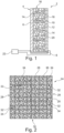
- Fig. 2 shows an electrolytic cell 24 with a modified design.
- a cathode 26 is formed as a container and includes side walls 28 and a bottom plate 30 and an array of solid oxide membrane anodes 32, each of which is shaped as a one end closed tube with a current collector 34 inside.
- the membrane anodes 32 are created by coating anodes with the respective membrane material.
- a wire mesh structure 36 is connected to the cathode 26 and partially fills a space between the anodes 32 and the cathode 26 to reduce the average distance between the anodes 32 and elements that provide the cathodic potential.
- the remaining space between the anodes 32 is filled with a mixture of the metal oxide powder 18 to be reduced and the solid electrolyte powder 20.
- the average particle size of the electrolyte powder is clearly lower than the average particle size of the metal oxide powder.
- the electrolytic powder thereby fills the gaps between the particles of the metal oxide 18 and provides a conducting path for oxygen ions produced as a result of the reduction towards the solid oxide membrane.
- the metal powder can be separated after the electrolysis and the electrolyte powder is reusable.
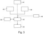
- Fig. 3 shows a method for extracting metal and oxygen from powdered metal oxides in an electrolytic cell, comprising a container, a cathode, an anode, and an oxygen-ion-conducting membrane.
- the method comprises providing 38 a solid oxygen ion conducting electrolyte powder into a container, providing 40 a feedstock comprising at least one metal oxide in powdered form into the container, applying 42 an electric potential across the cathode and the anode, the cathode being in communication with the electrolyte powder and the anode being in communication with the membrane in communication with the electrolyte powder, such that at least one respective metallic species of the at least one metal oxide is reduced at the cathode and oxygen is oxidized at the anode to form molecular oxygen.
- the potential across the cathode and the anode is greater than the dissociation potential of the at least one metal oxide and less than the dissociation potential of the solid electrolyte powder and the membrane.
- the electrolyte powder and the feedstock may be mixed 44 before or after providing them. During the reduction process, molecular oxygen can be collected 46 at the anode.
- a conducting structure such as a wire mesh, can be arranged 48 into a space between the cathode and the anode in electrical contact with the cathode before applying the electric potential.
- obtained metal is separated 50 from the electrolyte powder through a separation process.
Landscapes
- Chemical & Material Sciences (AREA)
- Engineering & Computer Science (AREA)
- Chemical Kinetics & Catalysis (AREA)
- Electrochemistry (AREA)
- Materials Engineering (AREA)
- Metallurgy (AREA)
- Organic Chemistry (AREA)
- Inorganic Chemistry (AREA)
- Ceramic Engineering (AREA)
- Electrolytic Production Of Non-Metals, Compounds, Apparatuses Therefor (AREA)
Claims (20)
- Verfahren zum Extrahieren von Metall und Sauerstoff aus Metalloxidpulvern in einer elektrolytischen Zelle, die einen Behälter, eine Kathode, eine Anode und eine Sauerstoffionen leitende Membran umfasst, wobei das Verfahren Folgendes umfasst:- Bereitstellen eines festen Sauerstoffionen leitenden Elektrolytpulvers in einem Behälter,- Bereitstellen eines Ausgangsmaterials, das mindestens ein Metalloxid in Pulverform umfasst, in dem Behälter,- Anlegen eines elektrischen Potentials über die Kathode und die Anode, wobei sich die Kathode in Kommunikation mit dem Elektrolytpulver befindet und sich die Anode in Kommunikation mit der Membran in Kommunikation mit dem Elektrolytpulver befindet, sodass mindestens eine jeweilige metallische Spezies des mindestens einen Metalloxids an der Kathode reduziert wird und Sauerstoff an der Anode unter Bildung von molekularem Sauerstoff oxidiert wird,wobei das Potential über die Kathode und die Anode größer als das Dissoziationspotential des mindestens einen Metalloxids und kleiner als das Dissoziationspotential des festen Elektrolytpulvers und der Membran ist.
- Verfahren nach Anspruch 1, ferner umfassend das Mischen des Elektrolytpulvers und des Ausgangsmaterials.
- Verfahren nach Anspruch 1, wobei das Ausgangsmaterial mindestens eines aus einer Gruppe von Materialien oder eine chemische Verbindung, die mindestens eines aus der Gruppe von Materialien umfasst, umfasst, wobei die Gruppe aus Folgendem besteht:- Eisen,- Titan,- Regolith.
- Verfahren nach Anspruch 1, wobei das Elektrolytpulver mindestens eines aus einer Gruppe von Materialien umfasst, wobei die Gruppe aus mit Seltenerde oder Erdalkali dotierten Oxiden auf Basis von Zirconiumdioxid, Cerdioxid, Hafniumdioxid und Thoriumdioxid besteht.
- Verfahren nach Anspruch 1, wobei das Elektrolytpulver gemischte elektronische Sauerstoffionenleiter umfasst.
- Verfahren nach Anspruch 1, wobei die Sauerstoffionen leitende Membran aus einer Gruppe von Materialien ausgewählt ist, wobei die Gruppe mit Seltenerde oder Erdalkali dotierte Oxide auf Basis von Zirconiumdioxid, Cerdioxid, Hafniumdioxid und Thoriumdioxid umfasst.
- Verfahren nach Anspruch 6, wobei die Membran mit Yttriumdioxid stabilisiertes Zirconiumdioxid umfasst.
- Verfahren nach Anspruch 1, wobei eine mittlere Teilchengröße des festen Elektrolytpulvers kleiner als eine mittlere Teilchengröße des Ausgangsmaterialpulvers ist.
- Verfahren nach Anspruch 1, wobei die elektrolytische Zelle bei einer Temperatur von über etwa 500 °C betrieben wird.
- Verfahren nach Anspruch 1, wobei die elektrolytische Zelle bei einer Temperatur im Bereich von etwa 500 °C bis etwa 1300 °C betrieben wird.
- Verfahren nach Anspruch 1, ferner umfassend das Sammeln von molekularem Sauerstoff an der Anode.
- Verfahren nach Anspruch 1, ferner umfassend das Anordnen einer leitenden Struktur in einem Raum zwischen der Kathode und der Anode in elektrischem Kontakt mit der Kathode als Vorbereitungsschritt vor dem Anlegen des elektrischen Potentials.
- Verfahren nach Anspruch 1, ferner umfassend das Trennen von erhaltenem Metall von dem Elektrolytpulver durch einen Trennvorgang, wobei der Trennvorgang ausgewählt ist aus einer Gruppe von Trennvorgängen, wobei die Gruppe Folgendes umfasst:- Sieben,- Vibrationstrennung,- magnetische Trennung,- elektrostatische Trennung,- Luftsichtung,- Absetzung und- eine Kombination davon.
- System zum Extrahieren von Metall und Sauerstoff aus Metalloxidpulvern, wobei das System Folgendes umfasst:- eine elektrolytische Zelle mit einem Behälter, einer Kathode, einer Anode und einer Sauerstoffionen leitenden Membran,- ein festes Sauerstoffionen leitendes Elektrolytpulver und- eine Stromversorgung,wobei die Kathode und die Anode unter Bildung eines Aufnahmeraums in einem Abstand voneinander an dem Behälter angeordnet sind,wobei die Membran zwischen der Kathode und der Anode angeordnet ist und die Anode berührt,wobei das elektrolytische Pulver in dem Aufnahmeraum in Kommunikation mit der Kathode und der Membran bereitgestellt ist,wobei die Stromversorgung mit der Kathode und der Anode verbindbar ist, um ein elektrisches Potential selektiv über die Kathode und die Anode anzulegen,wobei das System zum Reduzieren mindestens einer jeweiligen metallischen Spezies des mindestens einen Metalloxids von Ausgangsmaterial, das in das Elektrolytpulver gemischt und davon umgeben ist, durch Anlegen des elektrischen Potentials ausgelegt ist, wobei das Potential größer als das Dissoziationspotential des mindestens einen Metalloxids und kleiner als das Dissoziationspotential des festen Elektrolytpulvers und der Membran ist.
- System nach Anspruch 14, wobei das Elektrolytpulver mindestens eines aus einer Gruppe von Materialien umfasst, wobei die Gruppe aus mit Seltenerde oder Erdalkali dotierten Oxiden auf Basis von Zirconiumdioxid, Cerdioxid, Hafniumdioxid und Thoriumdioxid besteht.
- System nach Anspruch 14, wobei das feste Elektrolytpulver gemischte elektronische Sauerstoffionenleiter umfasst.
- System nach Anspruch 14, wobei die Sauerstoffionen leitende Membran aus einer Gruppe von Materialien ausgewählt ist, wobei die Gruppe mit Seltenerde oder Erdalkali dotierte Oxide auf Basis von Zirconiumdioxid, Cerdioxid, Hafniumdioxid und Thoriumdioxid umfasst, insbesondere mit Yttriumdioxid stabilisiertes Zirconiumdioxid.
- System nach Anspruch 14, ferner umfassend eine leitende Struktur, insbesondere Nadeln und/oder Drahtgeflecht, in dem Aufnahmeraum zwischen der Kathode und der Anode in elektrischem Kontakt mit der Kathode.
- System nach Anspruch 14, ferner umfassend ein Array von Anoden, insbesondere Kapillaranoden, die sich in Richtung der Kathode erstrecken.
- System nach Anspruch 18 und 19, wobei die leitende Struktur mindestens ein Drahtgeflecht umfasst, wobei die Kapillaranoden zumindest teilweise von Geflechtzellen umgeben sind.
Applications Claiming Priority (1)
| Application Number | Priority Date | Filing Date | Title |
|---|---|---|---|
| US17/509,394 US12534818B2 (en) | 2021-10-25 | 2021-10-25 | Method and system for extracting metal and oxygen from powdered metal oxides |
Publications (3)
| Publication Number | Publication Date |
|---|---|
| EP4170066A2 EP4170066A2 (de) | 2023-04-26 |
| EP4170066A3 EP4170066A3 (de) | 2023-05-10 |
| EP4170066B1 true EP4170066B1 (de) | 2024-03-27 |
Family
ID=83898351
Family Applications (1)
| Application Number | Title | Priority Date | Filing Date |
|---|---|---|---|
| EP22201867.3A Active EP4170066B1 (de) | 2021-10-25 | 2022-10-17 | Verfahren und system zur extraktion von metall und sauerstoff aus metallpulvern |
Country Status (2)
| Country | Link |
|---|---|
| US (1) | US12534818B2 (de) |
| EP (1) | EP4170066B1 (de) |
Families Citing this family (2)
| Publication number | Priority date | Publication date | Assignee | Title |
|---|---|---|---|---|
| US20250051947A1 (en) * | 2023-08-07 | 2025-02-13 | Form Energy, Inc. | Electrochemical reactor and method for reducing iron from an iron-containing feedstock |
| US20250135430A1 (en) | 2023-11-01 | 2025-05-01 | Airbus Defence and Space GmbH | Reactor Device for Converting Powdered Metal Oxides and Conversion System Comprising Same |
Family Cites Families (12)
| Publication number | Priority date | Publication date | Assignee | Title |
|---|---|---|---|---|
| US5976345A (en) | 1997-01-06 | 1999-11-02 | Boston University | Method and apparatus for metal extraction and sensor device related thereto |
| US8658007B2 (en) * | 2005-07-15 | 2014-02-25 | The Trustees Of Boston University | Oxygen-producing inert anodes for SOM process |
| AR076863A1 (es) | 2009-05-12 | 2011-07-13 | Metalysis Ltd | Aparato y metodo para reduccion de materia prima solida. |
| BR112013011941A2 (pt) | 2010-11-18 | 2016-11-01 | Metalysis Ltd | método e sistema para reduzir eletroliticamente uma matéria - prima sólida |
| KR101770873B1 (ko) | 2010-11-18 | 2017-08-23 | 메탈리시스 리미티드 | 전기분해 장치 |
| GB2514679A (en) | 2011-10-04 | 2014-12-03 | Metalysis Ltd | Electrolytic production of powder |
| GB201223375D0 (en) | 2012-12-24 | 2013-02-06 | Metalysis Ltd | Method and apparatus for producing metal by electrolytic reduction |
| GB2534332A (en) | 2014-06-26 | 2016-07-27 | Metalysis Ltd | Method and apparatus for producing metallic tantalum by electrolytic reduction of a feedstock |
| GB201411433D0 (en) | 2014-06-26 | 2014-08-13 | Metalysis Ltd | Method and apparatus for electrolytic reduction of a feedstock comprising oxygen and a first metal |
| WO2016018433A1 (en) * | 2014-08-01 | 2016-02-04 | Savannah River Nuclear Solutions, Llc | Electrochemical cell for recovery of metals from solid metal oxides |
| GB201609141D0 (en) | 2016-05-24 | 2016-07-06 | Metalysis Ltd | Manufacturing apparatus and method |
| EP3812483B1 (de) | 2019-10-24 | 2024-01-31 | Airbus Defence and Space GmbH | Elektrolysevorrichtung zur elektrolytischen produktion von sauerstoff aus oxidhaltigem ausgangsmaterial |
-
2021
- 2021-10-25 US US17/509,394 patent/US12534818B2/en active Active
-
2022
- 2022-10-17 EP EP22201867.3A patent/EP4170066B1/de active Active
Also Published As
| Publication number | Publication date |
|---|---|
| EP4170066A3 (de) | 2023-05-10 |
| US20230131891A1 (en) | 2023-04-27 |
| EP4170066A2 (de) | 2023-04-26 |
| US12534818B2 (en) | 2026-01-27 |
Similar Documents
| Publication | Publication Date | Title |
|---|---|---|
| JP4689773B2 (ja) | 金属抽出法及び金属抽出装置 | |
| Wang et al. | Solid state reactions: an electrochemical approach in molten salts | |
| EP4170066B1 (de) | Verfahren und system zur extraktion von metall und sauerstoff aus metallpulvern | |
| Fray | Emerging molten salt technologies for metals production | |
| AU2002349216B2 (en) | A method for electrowinning of titanium metal or alloy from titanium oxide containing compound in the liquid state | |
| CN102625862B (zh) | 用于还原固体原料的设备和方法 | |
| JP6397426B2 (ja) | 電解還元による金属を製造するための方法及び装置 | |
| US10637115B2 (en) | Molten air rechargeable batteries | |
| Li et al. | Constructing metal-anode rechargeable batteries utilizing concomitant intercalation of Li–Mg dual cations into Mo 6 S 8 | |
| US10270139B1 (en) | Systems and methods for recycling electrochemical energy storage devices | |
| KR101765984B1 (ko) | 전기화학적 환원을 위한 모듈형 캐소드 조립체 및 그 사용 방법 | |
| US20170159193A1 (en) | Method and apparatus for electrolytic reduction of a feedstock comprising oxygen and a first metal | |
| JP7093580B2 (ja) | 溶融酸化物電解のためのシステムおよび方法 | |
| SE1350853A1 (sv) | Modulärt anodaggregat och metoder för användning av detsamma för elektrokemisk reduktion | |
| US20100288649A1 (en) | Magnesiothermic som process for production of metals | |
| US20220145484A1 (en) | An electrochemical method of reducing metal oxide | |
| EP4170067A2 (de) | System und verfahren zur extraktion von sauerstoff aus metallpulvern | |
| US8658007B2 (en) | Oxygen-producing inert anodes for SOM process | |
| Baba et al. | Niobium powder synthesized by calciothermic reduction of niobium hydroxide for use in capacitors | |
| Karr et al. | Ionic liquid facilitated recovery of metals and oxygen from regolith | |
| Soral et al. | A pilot-scale trial of an improved galvanic deoxidation process for refining molten copper | |
| Martin et al. | The electrochemical deoxidation of metal oxides by calcium using a solid oxide membrane | |
| Adrian et al. | Method and system for extractin metal and oxygen from powdered metal oxides (EP000004170066A2) | |
| US20250084553A1 (en) | Method And System For Molten Oxide Electrolysis | |
| Abiko et al. | Reduction of titanium oxide in molten salt medium |
Legal Events
| Date | Code | Title | Description |
|---|---|---|---|
| PUAI | Public reference made under article 153(3) epc to a published international application that has entered the european phase |
Free format text: ORIGINAL CODE: 0009012 |
|
| STAA | Information on the status of an ep patent application or granted ep patent |
Free format text: STATUS: THE APPLICATION HAS BEEN PUBLISHED |
|
| PUAL | Search report despatched |
Free format text: ORIGINAL CODE: 0009013 |
|
| AK | Designated contracting states |
Kind code of ref document: A2 Designated state(s): AL AT BE BG CH CY CZ DE DK EE ES FI FR GB GR HR HU IE IS IT LI LT LU LV MC ME MK MT NL NO PL PT RO RS SE SI SK SM TR |
|
| AK | Designated contracting states |
Kind code of ref document: A3 Designated state(s): AL AT BE BG CH CY CZ DE DK EE ES FI FR GB GR HR HU IE IS IT LI LT LU LV MC ME MK MT NL NO PL PT RO RS SE SI SK SM TR |
|
| RIC1 | Information provided on ipc code assigned before grant |
Ipc: C25B 13/07 20210101ALI20230331BHEP Ipc: C25B 13/02 20060101ALI20230331BHEP Ipc: C25C 7/08 20060101ALI20230331BHEP Ipc: C25C 7/04 20060101ALI20230331BHEP Ipc: C25C 7/02 20060101ALI20230331BHEP Ipc: C25C 7/00 20060101ALI20230331BHEP Ipc: C25C 5/00 20060101ALI20230331BHEP Ipc: C25B 1/02 20060101AFI20230331BHEP |
|
| STAA | Information on the status of an ep patent application or granted ep patent |
Free format text: STATUS: REQUEST FOR EXAMINATION WAS MADE |
|
| 17P | Request for examination filed |
Effective date: 20230530 |
|
| RBV | Designated contracting states (corrected) |
Designated state(s): AL AT BE BG CH CY CZ DE DK EE ES FI FR GB GR HR HU IE IS IT LI LT LU LV MC ME MK MT NL NO PL PT RO RS SE SI SK SM TR |
|
| GRAP | Despatch of communication of intention to grant a patent |
Free format text: ORIGINAL CODE: EPIDOSNIGR1 |
|
| STAA | Information on the status of an ep patent application or granted ep patent |
Free format text: STATUS: GRANT OF PATENT IS INTENDED |
|
| INTG | Intention to grant announced |
Effective date: 20231011 |
|
| GRAS | Grant fee paid |
Free format text: ORIGINAL CODE: EPIDOSNIGR3 |
|
| GRAA | (expected) grant |
Free format text: ORIGINAL CODE: 0009210 |
|
| STAA | Information on the status of an ep patent application or granted ep patent |
Free format text: STATUS: THE PATENT HAS BEEN GRANTED |
|
| AK | Designated contracting states |
Kind code of ref document: B1 Designated state(s): AL AT BE BG CH CY CZ DE DK EE ES FI FR GB GR HR HU IE IS IT LI LT LU LV MC ME MK MT NL NO PL PT RO RS SE SI SK SM TR |
|
| REG | Reference to a national code |
Ref country code: GB Ref legal event code: FG4D |
|
| REG | Reference to a national code |
Ref country code: CH Ref legal event code: EP |
|
| REG | Reference to a national code |
Ref country code: DE Ref legal event code: R096 Ref document number: 602022002567 Country of ref document: DE |
|
| REG | Reference to a national code |
Ref country code: IE Ref legal event code: FG4D |
|
| PG25 | Lapsed in a contracting state [announced via postgrant information from national office to epo] |
Ref country code: LT Free format text: LAPSE BECAUSE OF FAILURE TO SUBMIT A TRANSLATION OF THE DESCRIPTION OR TO PAY THE FEE WITHIN THE PRESCRIBED TIME-LIMIT Effective date: 20240327 |
|
| REG | Reference to a national code |
Ref country code: LT Ref legal event code: MG9D |
|
| PG25 | Lapsed in a contracting state [announced via postgrant information from national office to epo] |
Ref country code: GR Free format text: LAPSE BECAUSE OF FAILURE TO SUBMIT A TRANSLATION OF THE DESCRIPTION OR TO PAY THE FEE WITHIN THE PRESCRIBED TIME-LIMIT Effective date: 20240628 |
|
| PG25 | Lapsed in a contracting state [announced via postgrant information from national office to epo] |
Ref country code: RS Free format text: LAPSE BECAUSE OF FAILURE TO SUBMIT A TRANSLATION OF THE DESCRIPTION OR TO PAY THE FEE WITHIN THE PRESCRIBED TIME-LIMIT Effective date: 20240627 Ref country code: HR Free format text: LAPSE BECAUSE OF FAILURE TO SUBMIT A TRANSLATION OF THE DESCRIPTION OR TO PAY THE FEE WITHIN THE PRESCRIBED TIME-LIMIT Effective date: 20240327 |
|
| PG25 | Lapsed in a contracting state [announced via postgrant information from national office to epo] |
Ref country code: RS Free format text: LAPSE BECAUSE OF FAILURE TO SUBMIT A TRANSLATION OF THE DESCRIPTION OR TO PAY THE FEE WITHIN THE PRESCRIBED TIME-LIMIT Effective date: 20240627 Ref country code: NO Free format text: LAPSE BECAUSE OF FAILURE TO SUBMIT A TRANSLATION OF THE DESCRIPTION OR TO PAY THE FEE WITHIN THE PRESCRIBED TIME-LIMIT Effective date: 20240627 Ref country code: LT Free format text: LAPSE BECAUSE OF FAILURE TO SUBMIT A TRANSLATION OF THE DESCRIPTION OR TO PAY THE FEE WITHIN THE PRESCRIBED TIME-LIMIT Effective date: 20240327 Ref country code: HR Free format text: LAPSE BECAUSE OF FAILURE TO SUBMIT A TRANSLATION OF THE DESCRIPTION OR TO PAY THE FEE WITHIN THE PRESCRIBED TIME-LIMIT Effective date: 20240327 Ref country code: GR Free format text: LAPSE BECAUSE OF FAILURE TO SUBMIT A TRANSLATION OF THE DESCRIPTION OR TO PAY THE FEE WITHIN THE PRESCRIBED TIME-LIMIT Effective date: 20240628 Ref country code: FI Free format text: LAPSE BECAUSE OF FAILURE TO SUBMIT A TRANSLATION OF THE DESCRIPTION OR TO PAY THE FEE WITHIN THE PRESCRIBED TIME-LIMIT Effective date: 20240327 Ref country code: BG Free format text: LAPSE BECAUSE OF FAILURE TO SUBMIT A TRANSLATION OF THE DESCRIPTION OR TO PAY THE FEE WITHIN THE PRESCRIBED TIME-LIMIT Effective date: 20240327 |
|
| REG | Reference to a national code |
Ref country code: NL Ref legal event code: MP Effective date: 20240327 |
|
| PG25 | Lapsed in a contracting state [announced via postgrant information from national office to epo] |
Ref country code: SE Free format text: LAPSE BECAUSE OF FAILURE TO SUBMIT A TRANSLATION OF THE DESCRIPTION OR TO PAY THE FEE WITHIN THE PRESCRIBED TIME-LIMIT Effective date: 20240327 Ref country code: LV Free format text: LAPSE BECAUSE OF FAILURE TO SUBMIT A TRANSLATION OF THE DESCRIPTION OR TO PAY THE FEE WITHIN THE PRESCRIBED TIME-LIMIT Effective date: 20240327 |
|
| PG25 | Lapsed in a contracting state [announced via postgrant information from national office to epo] |
Ref country code: NL Free format text: LAPSE BECAUSE OF FAILURE TO SUBMIT A TRANSLATION OF THE DESCRIPTION OR TO PAY THE FEE WITHIN THE PRESCRIBED TIME-LIMIT Effective date: 20240327 |
|
| REG | Reference to a national code |
Ref country code: AT Ref legal event code: MK05 Ref document number: 1669964 Country of ref document: AT Kind code of ref document: T Effective date: 20240327 |
|
| PG25 | Lapsed in a contracting state [announced via postgrant information from national office to epo] |
Ref country code: NL Free format text: LAPSE BECAUSE OF FAILURE TO SUBMIT A TRANSLATION OF THE DESCRIPTION OR TO PAY THE FEE WITHIN THE PRESCRIBED TIME-LIMIT Effective date: 20240327 |
|
| PG25 | Lapsed in a contracting state [announced via postgrant information from national office to epo] |
Ref country code: IS Free format text: LAPSE BECAUSE OF FAILURE TO SUBMIT A TRANSLATION OF THE DESCRIPTION OR TO PAY THE FEE WITHIN THE PRESCRIBED TIME-LIMIT Effective date: 20240727 |
|
| PG25 | Lapsed in a contracting state [announced via postgrant information from national office to epo] |
Ref country code: PT Free format text: LAPSE BECAUSE OF FAILURE TO SUBMIT A TRANSLATION OF THE DESCRIPTION OR TO PAY THE FEE WITHIN THE PRESCRIBED TIME-LIMIT Effective date: 20240729 Ref country code: SM Free format text: LAPSE BECAUSE OF FAILURE TO SUBMIT A TRANSLATION OF THE DESCRIPTION OR TO PAY THE FEE WITHIN THE PRESCRIBED TIME-LIMIT Effective date: 20240327 |
|
| PG25 | Lapsed in a contracting state [announced via postgrant information from national office to epo] |
Ref country code: ES Free format text: LAPSE BECAUSE OF FAILURE TO SUBMIT A TRANSLATION OF THE DESCRIPTION OR TO PAY THE FEE WITHIN THE PRESCRIBED TIME-LIMIT Effective date: 20240327 |
|
| PG25 | Lapsed in a contracting state [announced via postgrant information from national office to epo] |
Ref country code: EE Free format text: LAPSE BECAUSE OF FAILURE TO SUBMIT A TRANSLATION OF THE DESCRIPTION OR TO PAY THE FEE WITHIN THE PRESCRIBED TIME-LIMIT Effective date: 20240327 Ref country code: CZ Free format text: LAPSE BECAUSE OF FAILURE TO SUBMIT A TRANSLATION OF THE DESCRIPTION OR TO PAY THE FEE WITHIN THE PRESCRIBED TIME-LIMIT Effective date: 20240327 |
|
| PG25 | Lapsed in a contracting state [announced via postgrant information from national office to epo] |
Ref country code: AT Free format text: LAPSE BECAUSE OF FAILURE TO SUBMIT A TRANSLATION OF THE DESCRIPTION OR TO PAY THE FEE WITHIN THE PRESCRIBED TIME-LIMIT Effective date: 20240327 |
|
| PG25 | Lapsed in a contracting state [announced via postgrant information from national office to epo] |
Ref country code: PL Free format text: LAPSE BECAUSE OF FAILURE TO SUBMIT A TRANSLATION OF THE DESCRIPTION OR TO PAY THE FEE WITHIN THE PRESCRIBED TIME-LIMIT Effective date: 20240327 |
|
| PG25 | Lapsed in a contracting state [announced via postgrant information from national office to epo] |
Ref country code: SK Free format text: LAPSE BECAUSE OF FAILURE TO SUBMIT A TRANSLATION OF THE DESCRIPTION OR TO PAY THE FEE WITHIN THE PRESCRIBED TIME-LIMIT Effective date: 20240327 |
|
| PG25 | Lapsed in a contracting state [announced via postgrant information from national office to epo] |
Ref country code: SM Free format text: LAPSE BECAUSE OF FAILURE TO SUBMIT A TRANSLATION OF THE DESCRIPTION OR TO PAY THE FEE WITHIN THE PRESCRIBED TIME-LIMIT Effective date: 20240327 Ref country code: SK Free format text: LAPSE BECAUSE OF FAILURE TO SUBMIT A TRANSLATION OF THE DESCRIPTION OR TO PAY THE FEE WITHIN THE PRESCRIBED TIME-LIMIT Effective date: 20240327 Ref country code: RO Free format text: LAPSE BECAUSE OF FAILURE TO SUBMIT A TRANSLATION OF THE DESCRIPTION OR TO PAY THE FEE WITHIN THE PRESCRIBED TIME-LIMIT Effective date: 20240327 Ref country code: PT Free format text: LAPSE BECAUSE OF FAILURE TO SUBMIT A TRANSLATION OF THE DESCRIPTION OR TO PAY THE FEE WITHIN THE PRESCRIBED TIME-LIMIT Effective date: 20240729 Ref country code: PL Free format text: LAPSE BECAUSE OF FAILURE TO SUBMIT A TRANSLATION OF THE DESCRIPTION OR TO PAY THE FEE WITHIN THE PRESCRIBED TIME-LIMIT Effective date: 20240327 Ref country code: IS Free format text: LAPSE BECAUSE OF FAILURE TO SUBMIT A TRANSLATION OF THE DESCRIPTION OR TO PAY THE FEE WITHIN THE PRESCRIBED TIME-LIMIT Effective date: 20240727 Ref country code: ES Free format text: LAPSE BECAUSE OF FAILURE TO SUBMIT A TRANSLATION OF THE DESCRIPTION OR TO PAY THE FEE WITHIN THE PRESCRIBED TIME-LIMIT Effective date: 20240327 Ref country code: EE Free format text: LAPSE BECAUSE OF FAILURE TO SUBMIT A TRANSLATION OF THE DESCRIPTION OR TO PAY THE FEE WITHIN THE PRESCRIBED TIME-LIMIT Effective date: 20240327 Ref country code: CZ Free format text: LAPSE BECAUSE OF FAILURE TO SUBMIT A TRANSLATION OF THE DESCRIPTION OR TO PAY THE FEE WITHIN THE PRESCRIBED TIME-LIMIT Effective date: 20240327 Ref country code: AT Free format text: LAPSE BECAUSE OF FAILURE TO SUBMIT A TRANSLATION OF THE DESCRIPTION OR TO PAY THE FEE WITHIN THE PRESCRIBED TIME-LIMIT Effective date: 20240327 |
|
| PG25 | Lapsed in a contracting state [announced via postgrant information from national office to epo] |
Ref country code: IT Free format text: LAPSE BECAUSE OF FAILURE TO SUBMIT A TRANSLATION OF THE DESCRIPTION OR TO PAY THE FEE WITHIN THE PRESCRIBED TIME-LIMIT Effective date: 20240327 |
|
| PG25 | Lapsed in a contracting state [announced via postgrant information from national office to epo] |
Ref country code: IT Free format text: LAPSE BECAUSE OF FAILURE TO SUBMIT A TRANSLATION OF THE DESCRIPTION OR TO PAY THE FEE WITHIN THE PRESCRIBED TIME-LIMIT Effective date: 20240327 |
|
| REG | Reference to a national code |
Ref country code: DE Ref legal event code: R097 Ref document number: 602022002567 Country of ref document: DE |
|
| PG25 | Lapsed in a contracting state [announced via postgrant information from national office to epo] |
Ref country code: DK Free format text: LAPSE BECAUSE OF FAILURE TO SUBMIT A TRANSLATION OF THE DESCRIPTION OR TO PAY THE FEE WITHIN THE PRESCRIBED TIME-LIMIT Effective date: 20240327 |
|
| PG25 | Lapsed in a contracting state [announced via postgrant information from national office to epo] |
Ref country code: DK Free format text: LAPSE BECAUSE OF FAILURE TO SUBMIT A TRANSLATION OF THE DESCRIPTION OR TO PAY THE FEE WITHIN THE PRESCRIBED TIME-LIMIT Effective date: 20240327 |
|
| PLBE | No opposition filed within time limit |
Free format text: ORIGINAL CODE: 0009261 |
|
| STAA | Information on the status of an ep patent application or granted ep patent |
Free format text: STATUS: NO OPPOSITION FILED WITHIN TIME LIMIT |
|
| 26N | No opposition filed |
Effective date: 20250103 |
|
| PG25 | Lapsed in a contracting state [announced via postgrant information from national office to epo] |
Ref country code: SI Free format text: LAPSE BECAUSE OF FAILURE TO SUBMIT A TRANSLATION OF THE DESCRIPTION OR TO PAY THE FEE WITHIN THE PRESCRIBED TIME-LIMIT Effective date: 20240327 |
|
| PG25 | Lapsed in a contracting state [announced via postgrant information from national office to epo] |
Ref country code: MC Free format text: LAPSE BECAUSE OF FAILURE TO SUBMIT A TRANSLATION OF THE DESCRIPTION OR TO PAY THE FEE WITHIN THE PRESCRIBED TIME-LIMIT Effective date: 20240327 |
|
| PG25 | Lapsed in a contracting state [announced via postgrant information from national office to epo] |
Ref country code: LU Free format text: LAPSE BECAUSE OF NON-PAYMENT OF DUE FEES Effective date: 20241017 Ref country code: BE Free format text: LAPSE BECAUSE OF NON-PAYMENT OF DUE FEES Effective date: 20241031 |
|
| REG | Reference to a national code |
Ref country code: BE Ref legal event code: MM Effective date: 20241031 |
|
| PG25 | Lapsed in a contracting state [announced via postgrant information from national office to epo] |
Ref country code: IE Free format text: LAPSE BECAUSE OF NON-PAYMENT OF DUE FEES Effective date: 20241017 |
|
| PGFP | Annual fee paid to national office [announced via postgrant information from national office to epo] |
Ref country code: DE Payment date: 20251021 Year of fee payment: 4 |
|
| PGFP | Annual fee paid to national office [announced via postgrant information from national office to epo] |
Ref country code: FR Payment date: 20251030 Year of fee payment: 4 |
|
| PG25 | Lapsed in a contracting state [announced via postgrant information from national office to epo] |
Ref country code: CY Free format text: LAPSE BECAUSE OF FAILURE TO SUBMIT A TRANSLATION OF THE DESCRIPTION OR TO PAY THE FEE WITHIN THE PRESCRIBED TIME-LIMIT; INVALID AB INITIO Effective date: 20221017 |
|
| PG25 | Lapsed in a contracting state [announced via postgrant information from national office to epo] |
Ref country code: HU Free format text: LAPSE BECAUSE OF FAILURE TO SUBMIT A TRANSLATION OF THE DESCRIPTION OR TO PAY THE FEE WITHIN THE PRESCRIBED TIME-LIMIT; INVALID AB INITIO Effective date: 20221017 |