EP4169796A1 - Locomotive bogie driving device - Google Patents
Locomotive bogie driving device Download PDFInfo
- Publication number
- EP4169796A1 EP4169796A1 EP21859907.4A EP21859907A EP4169796A1 EP 4169796 A1 EP4169796 A1 EP 4169796A1 EP 21859907 A EP21859907 A EP 21859907A EP 4169796 A1 EP4169796 A1 EP 4169796A1
- Authority
- EP
- European Patent Office
- Prior art keywords
- axle
- traction
- driving
- driven gear
- traction motors
- Prior art date
- Legal status (The legal status is an assumption and is not a legal conclusion. Google has not performed a legal analysis and makes no representation as to the accuracy of the status listed.)
- Withdrawn
Links
- 230000003137 locomotive effect Effects 0.000 title claims abstract description 25
- 230000005540 biological transmission Effects 0.000 claims abstract description 24
- 238000005299 abrasion Methods 0.000 abstract description 4
- 230000003247 decreasing effect Effects 0.000 description 3
- 238000011982 device technology Methods 0.000 description 1
- 238000012986 modification Methods 0.000 description 1
- 230000004048 modification Effects 0.000 description 1
- 239000000725 suspension Substances 0.000 description 1
Images

Classifications
-
- B—PERFORMING OPERATIONS; TRANSPORTING
- B61—RAILWAYS
- B61C—LOCOMOTIVES; MOTOR RAILCARS
- B61C3/00—Electric locomotives or railcars
-
- B—PERFORMING OPERATIONS; TRANSPORTING
- B61—RAILWAYS
- B61C—LOCOMOTIVES; MOTOR RAILCARS
- B61C9/00—Locomotives or motor railcars characterised by the type of transmission system used; Transmission systems specially adapted for locomotives or motor railcars
- B61C9/38—Transmission systems in or for locomotives or motor railcars with electric motor propulsion
- B61C9/48—Transmission systems in or for locomotives or motor railcars with electric motor propulsion with motors supported on vehicle frames and driving axles, e.g. axle or nose suspension
-
- B—PERFORMING OPERATIONS; TRANSPORTING
- B61—RAILWAYS
- B61C—LOCOMOTIVES; MOTOR RAILCARS
- B61C9/00—Locomotives or motor railcars characterised by the type of transmission system used; Transmission systems specially adapted for locomotives or motor railcars
- B61C9/38—Transmission systems in or for locomotives or motor railcars with electric motor propulsion
- B61C9/48—Transmission systems in or for locomotives or motor railcars with electric motor propulsion with motors supported on vehicle frames and driving axles, e.g. axle or nose suspension
- B61C9/50—Transmission systems in or for locomotives or motor railcars with electric motor propulsion with motors supported on vehicle frames and driving axles, e.g. axle or nose suspension in bogies
Definitions
- the present invention relates to a railway locomotive bogie, in particular to a locomotive bogie driving device.
- driving devices for locomotive bogies all depend on a single motor to drive a single wheel set, and except the driving devices using permanent magnet direct drive technology, other locomotive driving devices are matched with the traction characteristics of a traction system by means of speed change of a gear pair.
- the existing driving device technology of driving a single wheel set by a single motor faces the following difficulties and challenges:
- the technical problem to be solved by the present invention is to provide a locomotive bogie driving device, which can increasethe maximum starting traction and meet the requirements of high-speed operation of a locomotive at the same time, aiming at the shortcomings of an existing driving device in which a single motor drives a single wheel set.
- the present invention provides a locomotive bogie driving device, including an axle on which a driven gear is mounted in an interference manner, wherein identical traction motors are symmetrically mounted on two sides of the axle, driving gears are mounted on rotary shafts of the traction motors in an interference manner respectively, and the driving gears on the traction motors mountedon the two sides of the axle are both engage with the driven gear to form a transmission gear pair.
- the driving device of the present invention is designed in such a way that double traction motors and double driving gears drive a driven gear on an axle simultaneously, so that when the same traction motors are used for driving, the driving torque and driving power of the driving device of the present invention can be significantly increased and even doubled; similarly, for designated single-axle traction power and traction force, when the driving device of the present invention is used, the driving torque and driving power of a single traction motor are significantly decreased end even halved, so that the volume and weight of the single traction motor are smaller, and the decrease in the outer diameter of the single traction motor provides ample space for a bogie traction rod to cross under the traction motors.
- the driving device of the present invention adopts matching of double driving gears with a single driven gear, so the abrasion difference between the driven gear and the driving gears is smaller (in the case of traditional matching of a single driving gear with a single driven gear, the abrasion rate of the driving gear is far greater than that of the driven gear), and the abrasion matching of the driving gears and the driven gear of the present invention is better.
- the driving device of the present invention is designed with double traction motors and double driving gears, for designated single-axle traction power and traction force
- the driving torque and driving power of a single traction motor are significantly decreased and even halved. Therefore, the load of a transmission end bearing supporting the rotary shaft of the traction motor is also decreased and even halved, and the transmission end bearing of the traction motor may be a smaller bearing (usually the limit speed of the smaller bearing is higher), which can increase the limit speeds of the transmission end bearing and the traction motor, further exert the advantages of high efficiency and low loss of alternating current transmission, and bring huge convenience to the overall design of a locomotive traction system.
- the present invention just adopts the innovative design that double traction motors drive the same wheel set, so that the driving device of the present invention can meet the requirements of large starting traction and high-speed operation of a locomotive.
- the driving gears and the driven gear are mounted in one gearbox.
- two traction motors and one driven gear are provided, and the two traction motors are mounted side by side at the same height on the two sides of the axle, so that the driving gears on the rotary shafts of the two traction motors engage with the driven gear at the same mounting height, the driving force of the double driving gears on two sides of the driven gear is more uniform, and the operation of the driven gear is more stable and reliable.
- the traction motors share oneset of axle holding box, which is mounted on the axle by means of axle holding bearings on two sides respectively, so that the driving device of the present invention has a very compact structure, axle holding structures and a driven gear of a traditional driving device are fully used, the structural complexity is reduced to the greatest extent, and the serviceability of the driving device is improved.
- the driving gears are cantilevered on the rotary shafts of the traction motors.
- the traction motors are suspended on a frame of a bogie.
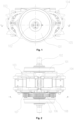
- a locomotive bogie driving device of the present invention in an embodiment includes a wheel set (including a wheel 101 and an axle 102), a traction motor 103, a traction motor 104, a driven gear 106, a driving gear 107, a driving gear 108 and a gearbox 105.
- the traction motor 103 has a rotary shaft 111 and a transmission end bearing 113, and the driving gear 107 is mounted on a transmission end of the rotary shaft 111 in a cantilever interference manner.
- the traction motor 104 has a rotary shaft 112 and a transmission end bearing 114, and the driving gear 108 is mounted on a transmission end of the rotary shaft 112 in a cantilever interference manner.
- the driving gear 107, the driving gear 108 and the driven gear 106 are mounted in one gearbox 105.
- the driven gear 106 is mounted on the axle 102 in an interference manner, the traction motor 103 and the traction motor 104 are symmetrically mounted on two sides of the axle 102, and the driving gear 107 and the driving gear 108 are located on two sides of the driven gear 106 respectively and are both engage with the driven gear 106 to form a transmission gear pair.
- the traction motor 103 and the traction motor 104 are mounted side by side at the same height on the two sides of the axle 102, and the driving gear 107 on the rotary shaft 111 of the traction motor 103 and the driving gear 108 on the rotary shaft 112 of the traction motor 104 engage with the driven gear 106 at the same mounting height and rotate relative to each other.
- the traction motor 103 and the traction motor 104 have the same specification and model, and the driving gear 107 and the driving gear 108 also have the same specification and model.
- the traction motor 103 and the traction motor 104 share oneset of axle holding box 110, and two sides of the axle holding box 110 are mounted on the axle 102 by means of axle holding bearings 109 respectively, so that the driving device of the present invention has a very compact structure, axle holding structures (axle holding bearings 109 and an axle holding box 110) and a driven gear 106 of a traditional driving device are fully used, the structural complexity is reduced to the greatest extent, and the serviceability of the driving device is improved.
- the driving gear 107 on the traction motor 103 and the driving gear 108 on the traction motor 104 drive the driven gear 106 mounted on the axle 102 simultaneously, and the driven gear 106 drives the axle 1 and the wheel 101 to rotate.
- the driving device of the present invention adopts an axle holding structure, but is not limited thereto.
- the present invention can similarly be applied to a frame suspension type driving device, that is, the traction motors 103 and 104 may also be suspended on a frame of a bogie.
Landscapes
- Engineering & Computer Science (AREA)
- Transportation (AREA)
- Mechanical Engineering (AREA)
- Chemical & Material Sciences (AREA)
- Combustion & Propulsion (AREA)
- Gear Transmission (AREA)
Abstract
Description
- The present invention relates to a railway locomotive bogie, in particular to a locomotive bogie driving device.
- At present, driving devices for locomotive bogies all depend on a single motor to drive a single wheel set, and except the driving devices using permanent magnet direct drive technology, other locomotive driving devices are matched with the traction characteristics of a traction system by means of speed change of a gear pair.
- The existing driving device technology of driving a single wheel set by a single motor faces the following difficulties and challenges:
- (1) For a high-speed locomotive, as large starting traction as possible is required. The starting traction is obtained from a formula: F=M×i/R. Herein, F is the starting traction; M is the torque of a traction motor; i is a transmission ratio, that is, the number of teeth of a driven gear/the number of teeth of a driving gear; R is the radius of a wheel. Generally speaking, the increase in the starting traction requires as large transmission ratio as possible. Due to the limitations of the bottom of a gearbox and the minimum number of teeth of the driving gear (generally not less than 17), the maximum number of teeth of the driven gear is limited when a gear modulus is given, so that the maximum transmission ratio of single-stage transmission is limited, and the starting traction can be increased only by increasing the torque of the traction motor. However, the torque of the traction motor is increased by increasing the outer diameter of the traction motor, which cannot be increased indefinitely due to the gear center distance between the driving gear and the driven gear (the gear center distance is the sum of the number of teeth of the driving gear and the driven gear multiplied by the modulus and divided by 2). Therefore, the torque of the traction motor of the traditional driving device has an upper limit, and cannot be increased indefinitely.
- (2) For the high-speed locomotive, due to the limitation of the limit speed of a transmission end bearing of the traction motor (the speed of the transmission end bearing of the traction motor is the speed of the wheel set multiplied by the transmission ratio), a relatively small transmission ratio is often selected for the high-speed locomotive. Therefore, the requirement of large starting traction of the traction motor of the high-speed locomotive for the transmission ratio is completely opposite to the requirement of high running speed of the high-speed locomotive for the transmission ratio, and they are a pair of contradictions. It is technically extremely difficult for a driving device for a high-speed passenger locomotive to meet the requirements of large starting traction and high-speed operation at the same time, so innovative structural design is needed.
- The technical problem to be solved by the present invention is to provide a locomotive bogie driving device, which can increasethe maximum starting traction and meet the requirements of high-speed operation of a locomotive at the same time, aiming at the shortcomings of an existing driving device in which a single motor drives a single wheel set.
- To solve the above technical problem, the present invention provides a locomotive bogie driving device, including an axle on which a driven gear is mounted in an interference manner, wherein identical traction motors are symmetrically mounted on two sides of the axle, driving gears are mounted on rotary shafts of the traction motors in an interference manner respectively, and the driving gears on the traction motors mountedon the two sides of the axle are both engage with the driven gear to form a transmission gear pair.
- The driving device of the present invention is designed in such a way that double traction motors and double driving gears drive a driven gear on an axle simultaneously, so that when the same traction motors are used for driving, the driving torque and driving power of the driving device of the present invention can be significantly increased and even doubled; similarly, for designated single-axle traction power and traction force, when the driving device of the present invention is used, the driving torque and driving power of a single traction motor are significantly decreased end even halved, so that the volume and weight of the single traction motor are smaller, and the decrease in the outer diameter of the single traction motor provides ample space for a bogie traction rod to cross under the traction motors.
- In addition, compared with traditional matching of a single driving gear with a single driven gear, the driving device of the present invention adopts matching of double driving gears with a single driven gear, so the abrasion difference between the driven gear and the driving gears is smaller (in the case of traditional matching of a single driving gear with a single driven gear, the abrasion rate of the driving gear is far greater than that of the driven gear), and the abrasion matching of the driving gears and the driven gear of the present invention is better.
- A particularly important point is as follows: just because the driving device of the present invention is designed with double traction motors and double driving gears, for designated single-axle traction power and traction force, when the driving device of the present invention is used, the driving torque and driving power of a single traction motor are significantly decreased and even halved. Therefore, the load of a transmission end bearing supporting the rotary shaft of the traction motor is also decreased and even halved, and the transmission end bearing of the traction motor may be a smaller bearing (usually the limit speed of the smaller bearing is higher), which can increase the limit speeds of the transmission end bearing and the traction motor, further exert the advantages of high efficiency and low loss of alternating current transmission, and bring huge convenience to the overall design of a locomotive traction system.
- The present invention just adopts the innovative design that double traction motors drive the same wheel set, so that the driving device of the present invention can meet the requirements of large starting traction and high-speed operation of a locomotive. Preferably, the driving gears and the driven gear are mounted in one gearbox. Preferably, two traction motors and one driven gear are provided, and the two traction motors are mounted side by side at the same height on the two sides of the axle, so that the driving gears on the rotary shafts of the two traction motors engage with the driven gear at the same mounting height, the driving force of the double driving gears on two sides of the driven gear is more uniform, and the operation of the driven gear is more stable and reliable.
- Preferably, the traction motors share oneset of axle holding box, which is mounted on the axle by means of axle holding bearings on two sides respectively, so that the driving device of the present invention has a very compact structure, axle holding structures and a driven gear of a traditional driving device are fully used, the structural complexity is reduced to the greatest extent, and the serviceability of the driving device is improved. Preferably, the driving gears are cantilevered on the rotary shafts of the traction motors. Preferably, the traction motors are suspended on a frame of a bogie.
- In order to describe the technical solutions in the embodiments of the present invention or in the prior art more clearly, the following briefly introduces the accompanying drawings required in the description of the embodiments or the prior art. Apparently, the accompanying drawings in the following description show some embodiments of the present invention, and a person of ordinary skill in the art may still derive other drawings from these drawings without any creative effort.
-
FIG. 1 is a front view of a driving device of the present invention. -
FIG. 2 is a top view of the driving device of the present invention. -
FIG. 3 is a cross-sectional view taken along line A-A inFIG. 2 . -
FIG. 4 is a cross-sectional view taken along line B-B inFIG. 1 . - In the figures:
101 - wheel; 102 - axle; 103 - traction motor; 104 - traction motor; 105 - gearbox; 106 - driven gear; 107 - driving gear; 108 - driving gear; 109 - axle holding bearing; 110 - axle holding box; 111 - rotary shaft; 112 - rotary shaft; 113 - transmission end bearing; 114 - transmission end bearing. - The present invention will be further described below with reference to specific preferred embodiments, but the protection scope of the present invention is not limited thereto.
- For the convenience of description, the relative positional relationships of components, such as upper, lower, left, and right, are described according to the layout directions of the drawings in the specification, and do not limit the structure of this patent.
- As shown in
FIG. 1 to FIG. 4 ,a locomotive bogie driving device of the present invention in an embodiment includes a wheel set (including awheel 101 and an axle 102), atraction motor 103, atraction motor 104, a drivengear 106, adriving gear 107, adriving gear 108 and agearbox 105. Thetraction motor 103 has arotary shaft 111 and a transmission end bearing 113, and thedriving gear 107 is mounted on a transmission end of therotary shaft 111 in a cantilever interference manner. Thetraction motor 104 has arotary shaft 112 and a transmission end bearing 114, and thedriving gear 108 is mounted on a transmission end of therotary shaft 112 in a cantilever interference manner. Thedriving gear 107, thedriving gear 108 and the drivengear 106 are mounted in onegearbox 105. - The driven
gear 106 is mounted on theaxle 102 in an interference manner, thetraction motor 103 and thetraction motor 104 are symmetrically mounted on two sides of theaxle 102, and thedriving gear 107 and thedriving gear 108 are located on two sides of the drivengear 106 respectively and are both engage with the drivengear 106 to form a transmission gear pair. - Preferably, the
traction motor 103 and thetraction motor 104 are mounted side by side at the same height on the two sides of theaxle 102, and thedriving gear 107 on therotary shaft 111 of thetraction motor 103 and thedriving gear 108 on therotary shaft 112 of thetraction motor 104 engage with the drivengear 106 at the same mounting height and rotate relative to each other. - In order to significantly increase and even double driving torque and driving power of the present invention, the
traction motor 103 and thetraction motor 104 have the same specification and model, and thedriving gear 107 and thedriving gear 108 also have the same specification and model. - The
traction motor 103 and thetraction motor 104 share oneset ofaxle holding box 110, and two sides of theaxle holding box 110 are mounted on theaxle 102 by means ofaxle holding bearings 109 respectively, so that the driving device of the present invention has a very compact structure, axle holding structures (axle holding bearings 109 and an axle holding box 110) and a drivengear 106 of a traditional driving device are fully used, the structural complexity is reduced to the greatest extent, and the serviceability of the driving device is improved. - When the present invention is used, the
driving gear 107 on thetraction motor 103 and thedriving gear 108 on thetraction motor 104 drive the drivengear 106 mounted on theaxle 102 simultaneously, and the drivengear 106 drives the axle 1 and thewheel 101 to rotate. - In this embodiment, the driving device of the present invention adopts an axle holding structure, but is not limited thereto. The present invention can similarly be applied to a frame suspension type driving device, that is, the
traction motors - The forgoing descriptions are only preferred embodiments of the present application, and do not limit the present application in any form. Although the present application is disclosed above with the preferred embodiments, the present application is not limited thereto. Some variations or modifications made by any skilled person familiar with the art using the disclosed technical contents without departing from the scope of the technical solution of the present application are equivalent to the embodiments, and all fall within the scope of the technical solution.
Claims (6)
- A locomotive bogie driving device, comprising an axle on which a driven gear is mounted in an interference manner, wherein identical traction motors are symmetrically mounted on two sides of the axle, driving gears are mounted on rotary shafts of the traction motors in an interference manner respectively, and the driving gears on the traction motors mountedon the two sides of the axle are both engage with the driven gear to form a transmission gear pair.
- The locomotive bogie driving device according to claim 1, wherein the driving gears and the driven gear are mounted in one gearbox.
- The locomotive bogie driving device according to claim 1, wherein two traction motors and one driven gear are provided, the two traction motors are mounted side by side at the same height on the two sides of the axle, and the driving gears on the rotary shafts of the two traction motors engage with the driven gear at the same mounting height.
- The locomotive bogie driving device according to claim 1, wherein the traction motors share oneset of axle holding box, which is mounted on the axle by means of axle holding bearings on two sides respectively.
- The locomotive bogie driving device according to claim 1, wherein the driving gears are cantilevered on the rotary shafts of the traction motors.
- The locomotive bogie driving device according to claim 1, wherein the traction motors are suspended on a frame of a bogie.
Applications Claiming Priority (2)
| Application Number | Priority Date | Filing Date | Title |
|---|---|---|---|
| CN202010857777.5A CN111976749A (en) | 2020-08-24 | 2020-08-24 | Driving device for locomotive bogie |
| PCT/CN2021/105155 WO2022042067A1 (en) | 2020-08-24 | 2021-07-08 | Locomotive bogie driving device |
Publications (2)
| Publication Number | Publication Date |
|---|---|
| EP4169796A1 true EP4169796A1 (en) | 2023-04-26 |
| EP4169796A4 EP4169796A4 (en) | 2024-08-07 |
Family
ID=73442652
Family Applications (1)
| Application Number | Title | Priority Date | Filing Date |
|---|---|---|---|
| EP21859907.4A Withdrawn EP4169796A4 (en) | 2020-08-24 | 2021-07-08 | LOCOMOTIVE BOGIE DRIVE DEVICE |
Country Status (4)
| Country | Link |
|---|---|
| EP (1) | EP4169796A4 (en) |
| CN (1) | CN111976749A (en) |
| BR (1) | BR112023002251A2 (en) |
| WO (1) | WO2022042067A1 (en) |
Families Citing this family (2)
| Publication number | Priority date | Publication date | Assignee | Title |
|---|---|---|---|---|
| CN111976749A (en) * | 2020-08-24 | 2020-11-24 | 中车株洲电力机车有限公司 | Driving device for locomotive bogie |
| CN112572478B (en) * | 2020-12-30 | 2024-04-16 | 中车资阳机车有限公司 | Traction transmission device for locomotive |
Family Cites Families (17)
| Publication number | Priority date | Publication date | Assignee | Title |
|---|---|---|---|---|
| DE171799C (en) * | 1905-08-18 | 1906-06-09 | Allgemeine Elektricitäts-Gesellschaft | Arrangement of the axle bearings of two motors acting on the same axle of an electrically powered vehicle by means of gear transmission. n |
| DE322753C (en) * | 1918-12-29 | 1920-07-07 | Bbc Brown Boveri & Cie | Vehicles are driven by axle motors with a reduction gear that work in pairs on the same drive axle |
| US1460170A (en) * | 1920-10-06 | 1923-06-26 | Westinghouse Electric & Mfg Co | Railway-motor mounting |
| GB273507A (en) * | 1926-07-19 | 1927-07-07 | Jacob Buchli | Improvements in driving gear for electrically driven locomotives |
| GB531722A (en) * | 1938-08-01 | 1941-01-09 | Schweizerische Lokomotiv | Improvements in or relating to a combined adhesion and rack drive for rail guided vehicles |
| BE490850A (en) * | 1948-09-20 | |||
| US5474155A (en) * | 1992-09-21 | 1995-12-12 | Sgp Verkehrstechnik Gesellschaft M.B.H. | Brake installation for railborne vehicles |
| DE19530155A1 (en) * | 1995-08-16 | 1997-02-20 | Siemens Ag | Single axle drive of electric traction vehicles |
| ES2170619B1 (en) * | 1999-11-18 | 2003-12-16 | Talgo Patentes | DISSEMINED TRACTION PROVISION APPLIED TO MONOEJE RAILWAY BEARINGS EQUIPPED WITH INDEPENDENT WHEELS. |
| CN200964117Y (en) * | 2006-09-05 | 2007-10-24 | 中国北车集团大同电力机车有限责任公司 | Driving device with separated brake axle |
| JP4818171B2 (en) * | 2007-03-15 | 2011-11-16 | 株式会社東芝 | Railway vehicle drive system |
| CN102490730A (en) * | 2011-12-02 | 2012-06-13 | 西南交通大学 | Device for driving bogie of electric locomotive |
| DE102013219397A1 (en) * | 2013-09-26 | 2015-03-26 | Zf Friedrichshafen Ag | driving device |
| CN203681547U (en) * | 2014-01-10 | 2014-07-02 | 南车株洲电力机车有限公司 | Driving device for narrow-gauge steering frame |
| CN110539756B (en) * | 2019-09-12 | 2024-05-10 | 中车山东机车车辆有限公司 | Railway vehicle bogie with power and railway vehicle |
| CN211107406U (en) * | 2019-10-22 | 2020-07-28 | 中交一公局第五工程有限公司 | Automatic steel bar transportation rail car and system |
| CN111976749A (en) * | 2020-08-24 | 2020-11-24 | 中车株洲电力机车有限公司 | Driving device for locomotive bogie |
-
2020
- 2020-08-24 CN CN202010857777.5A patent/CN111976749A/en active Pending
-
2021
- 2021-07-08 BR BR112023002251A patent/BR112023002251A2/en not_active Application Discontinuation
- 2021-07-08 EP EP21859907.4A patent/EP4169796A4/en not_active Withdrawn
- 2021-07-08 WO PCT/CN2021/105155 patent/WO2022042067A1/en not_active Ceased
Also Published As
| Publication number | Publication date |
|---|---|
| CN111976749A (en) | 2020-11-24 |
| WO2022042067A1 (en) | 2022-03-03 |
| EP4169796A4 (en) | 2024-08-07 |
| BR112023002251A2 (en) | 2023-03-07 |
Similar Documents
| Publication | Publication Date | Title |
|---|---|---|
| US6749532B2 (en) | Electric drive for a vehicle | |
| US20220009528A1 (en) | Permanent magnet direct-drive bogie and rail vehicle thereof | |
| CN101973277A (en) | Suspension type drive device for electric frame | |
| CN109466296A (en) | A central integrated double motor double reducer electric drive axle assembly | |
| US11233440B2 (en) | Compact drive unit for traction vehicles | |
| WO2022042067A1 (en) | Locomotive bogie driving device | |
| CN112572478B (en) | Traction transmission device for locomotive | |
| CN207631379U (en) | A kind of bogie applied on AGV trolleies | |
| CN201901134U (en) | Suspension type driving device of elastic frame | |
| CN112550442B (en) | Chassis running gear and wheeled robot | |
| US20230018057A1 (en) | Vehicle Drive Apparatus | |
| CN111287236A (en) | Drive axle drive system grader | |
| CN202463547U (en) | Travelling driving mechanism of crane | |
| CN110182224A (en) | Steering structure with enhanced steering stability | |
| CN207747745U (en) | A kind of gear assembly of electric wheel motor suspension | |
| CN212709370U (en) | Gearbox transmission system for bogie and bogie | |
| CN200974459Y (en) | Electric vehicle double-motor framework type combined driving device | |
| CN114013271A (en) | Electric drive system with torque vector distribution and control method thereof | |
| CN203381626U (en) | Mid-mounted single-motor-driven electric locomotive | |
| CN218480984U (en) | Single-motor full-drive transmission mechanism for suspension railcar | |
| CN208295086U (en) | The level Four external gear pump retarder of Portable hoister | |
| CN222950368U (en) | Differential planetary reducer | |
| CN219172388U (en) | Rail vehicle transmission structure and rail vehicle | |
| CN111342609A (en) | Integrated speed reducer | |
| CN208272787U (en) | A kind of electric machine structure of pure electric automobile |
Legal Events
| Date | Code | Title | Description |
|---|---|---|---|
| STAA | Information on the status of an ep patent application or granted ep patent |
Free format text: STATUS: THE INTERNATIONAL PUBLICATION HAS BEEN MADE |
|
| PUAI | Public reference made under article 153(3) epc to a published international application that has entered the european phase |
Free format text: ORIGINAL CODE: 0009012 |
|
| STAA | Information on the status of an ep patent application or granted ep patent |
Free format text: STATUS: REQUEST FOR EXAMINATION WAS MADE |
|
| 17P | Request for examination filed |
Effective date: 20230117 |
|
| AK | Designated contracting states |
Kind code of ref document: A1 Designated state(s): AL AT BE BG CH CY CZ DE DK EE ES FI FR GB GR HR HU IE IS IT LI LT LU LV MC MK MT NL NO PL PT RO RS SE SI SK SM TR |
|
| DAV | Request for validation of the european patent (deleted) | ||
| DAX | Request for extension of the european patent (deleted) | ||
| STAA | Information on the status of an ep patent application or granted ep patent |
Free format text: STATUS: THE APPLICATION HAS BEEN WITHDRAWN |
|
| A4 | Supplementary search report drawn up and despatched |
Effective date: 20240704 |
|
| RIC1 | Information provided on ipc code assigned before grant |
Ipc: B61C 9/50 20060101ALI20240628BHEP Ipc: B61C 3/00 20060101AFI20240628BHEP |
|
| 18W | Application withdrawn |
Effective date: 20240711 |