EP4169726A2 - Cleaning device, printer and method for cleaning a printer - Google Patents
Cleaning device, printer and method for cleaning a printer Download PDFInfo
- Publication number
- EP4169726A2 EP4169726A2 EP22189212.8A EP22189212A EP4169726A2 EP 4169726 A2 EP4169726 A2 EP 4169726A2 EP 22189212 A EP22189212 A EP 22189212A EP 4169726 A2 EP4169726 A2 EP 4169726A2
- Authority
- EP
- European Patent Office
- Prior art keywords
- cleaning
- fluid
- boundary
- point
- print head
- Prior art date
- Legal status (The legal status is an assumption and is not a legal conclusion. Google has not performed a legal analysis and makes no representation as to the accuracy of the status listed.)
- Pending
Links
Images


Classifications
-
- B—PERFORMING OPERATIONS; TRANSPORTING
- B41—PRINTING; LINING MACHINES; TYPEWRITERS; STAMPS
- B41J—TYPEWRITERS; SELECTIVE PRINTING MECHANISMS, i.e. MECHANISMS PRINTING OTHERWISE THAN FROM A FORME; CORRECTION OF TYPOGRAPHICAL ERRORS
- B41J25/00—Actions or mechanisms not otherwise provided for
- B41J25/304—Bodily-movable mechanisms for print heads or carriages movable towards or from paper surface
-
- B—PERFORMING OPERATIONS; TRANSPORTING
- B41—PRINTING; LINING MACHINES; TYPEWRITERS; STAMPS
- B41J—TYPEWRITERS; SELECTIVE PRINTING MECHANISMS, i.e. MECHANISMS PRINTING OTHERWISE THAN FROM A FORME; CORRECTION OF TYPOGRAPHICAL ERRORS
- B41J2/00—Typewriters or selective printing mechanisms characterised by the printing or marking process for which they are designed
- B41J2/005—Typewriters or selective printing mechanisms characterised by the printing or marking process for which they are designed characterised by bringing liquid or particles selectively into contact with a printing material
- B41J2/01—Ink jet
- B41J2/135—Nozzles
- B41J2/165—Preventing or detecting of nozzle clogging, e.g. cleaning, capping or moistening for nozzles
- B41J2/16517—Cleaning of print head nozzles
- B41J2/1652—Cleaning of print head nozzles by driving a fluid through the nozzles to the outside thereof, e.g. by applying pressure to the inside or vacuum at the outside of the print head
- B41J2/16532—Cleaning of print head nozzles by driving a fluid through the nozzles to the outside thereof, e.g. by applying pressure to the inside or vacuum at the outside of the print head by applying vacuum only
-
- B—PERFORMING OPERATIONS; TRANSPORTING
- B41—PRINTING; LINING MACHINES; TYPEWRITERS; STAMPS
- B41J—TYPEWRITERS; SELECTIVE PRINTING MECHANISMS, i.e. MECHANISMS PRINTING OTHERWISE THAN FROM A FORME; CORRECTION OF TYPOGRAPHICAL ERRORS
- B41J2/00—Typewriters or selective printing mechanisms characterised by the printing or marking process for which they are designed
- B41J2/005—Typewriters or selective printing mechanisms characterised by the printing or marking process for which they are designed characterised by bringing liquid or particles selectively into contact with a printing material
- B41J2/01—Ink jet
- B41J2/135—Nozzles
- B41J2/165—Preventing or detecting of nozzle clogging, e.g. cleaning, capping or moistening for nozzles
- B41J2/16517—Cleaning of print head nozzles
- B41J2/16552—Cleaning of print head nozzles using cleaning fluids
-
- B—PERFORMING OPERATIONS; TRANSPORTING
- B41—PRINTING; LINING MACHINES; TYPEWRITERS; STAMPS
- B41J—TYPEWRITERS; SELECTIVE PRINTING MECHANISMS, i.e. MECHANISMS PRINTING OTHERWISE THAN FROM A FORME; CORRECTION OF TYPOGRAPHICAL ERRORS
- B41J25/00—Actions or mechanisms not otherwise provided for
- B41J2025/008—Actions or mechanisms not otherwise provided for comprising a plurality of print heads placed around a drum
Definitions
- the invention relates to a cleaning device according to the preamble of claim 1, or a printing machine according to the preamble of claim 10 and a method for cleaning a printing machine according to the preamble of claim 12.
- Non-impact printing methods for example thermographic methods or in particular the inkjet method
- a non-impact printing machine usually has at least one image-generating device, in particular at least one printing unit with preferably at least one print head, for example preferably an inkjet print head.
- individual drops of a printing fluid are ejected from at least one volume of the print head as required and transferred to a printing material, resulting in a printed image on the printing material.
- By individually controlling a large number of volumes of the print head different print images are generated, for example, which are, for example, individualized and/or personalized and/or are produced cost-effectively, for example, in particular in small editions.
- Soiling occurs again and again in printing units, for example due to dried coating materials such as printing ink or ink or due to parts of a printing material such as paper fibers or due to dust or the like or due to mixtures of the substances mentioned.
- nozzles of print heads can be narrowed or clogged, which can lead to incorrect application of coating agent.
- Such contamination can have negative consequences both inside nozzles and on the outside nozzle surfaces of print heads.
- Cleaning devices are used to clean the nozzle surface.
- Two print heads arranged one behind the other in the transverse direction are spaced apart from one another, for example by a positioning gap. For example, contamination can settle in this positioning gap and lead to negative consequences in subsequent printing processes.
- a printing machine is known, wherein a longitudinal direction of a fluid supply opening and/or a longitudinal direction of a fluid discharge and/or a longitudinal direction of a fluid suction is aligned parallel to the positioning gap in order to clean it.
- the longitudinal extent of the fluid supply opening is smaller than the extent of the nozzle surface of the at least one print head in the direction of the longitudinal extent of the fluid supply opening.
- the object of the invention is to provide a cleaning device, a printing press and a method for cleaning a printing press to accomplish.
- a cleaning device is advantageously provided.
- the cleaning device preferably has at least one cleaning element.
- the at least one cleaning element preferably has at least one fluid supply with at least one outlet opening for cleaning fluid.
- the at least one cleaning element preferably has at least one sliding surface.
- the at least one sliding surface preferably has a greater extent in a cleaning direction than orthogonally to the cleaning direction.
- a projection plane is preferably arranged orthogonally to the cleaning direction.
- At least one point of the at least one fluid supply is preferably arranged in the projection plane further away from a plane spanned by a z-direction and a central axis of the at least one cleaning element than at least one boundary point of the at least one sliding surface with the shortest distance to the at least one plane spanned by the z-direction and the central axis.
- this enables the at least one contact surface of a print head to be wetted vertically with cleaning agent.
- a projection of the at least one fluid supply in a plane of projection preferably at least partially overlays a projection of the at least one sliding surface in the plane of projection.
- the printing machine preferably has at least one nozzle bar with at least one print head.
- the at least one print head preferably has at least one nozzle surface and at least one contact surface.
- the printing machine preferably has the at least one cleaning device.
- the at least one cleaning device is preferably designed to clean the at least one nozzle surface and the at least one contact surface.
- a method for cleaning the printing press is provided.
- the at least one print head of at least one nozzle bar of the printing press is preferably cleaned by the at least one cleaning device.
- the at least one print head preferably has the at least one nozzle surface and the at least one contact surface.
- the at least one cleaning device preferably ejects cleaning fluid by means of the at least one fluid supply of the at least one cleaning element.
- the at least one contact surface is preferably wetted with cleaning fluid by the at least one fluid supply.
- the cleaning device advantageously comprises at least one fluid inlet, preferably designed as a fluid inlet opening, and/or at least one first fluid outlet, preferably designed as a fluid outlet, and/or at least one second fluid outlet, preferably designed as a fluid suction.
- the cleaning device advantageously comprises the at least one fluid supply opening and/or the at least one fluid discharge and/or the at least one fluid suction, the longitudinal direction of the fluid supply opening and/or the longitudinal direction of the fluid discharge and/or the longitudinal direction of the fluid suction being parallel to the respective positioning gap to be cleaned is positioned.
- penetration of a cleaning agent into the positioning gap is ensured and/or cleaning of the respective positioning gap is possible.
- an intensive cleaning of the positioning gap is thus possible.
- the flow rate of fluid within the first fluid drain is maximized by its preferred design.
- Cleaning of the at least one contact surface of the at least one print head is advantageously optimized.
- two delimitation points of a delimitation of the at least one fluid suction have the greatest possible distance from one another, which has a minimum length that is greater than at least one delimitation of a relevant one Exit face of a printhead in question is in a direction oriented parallel to the minimum length of fluid suction.
- the cleaning device comprises at least two cleaning elements.
- the at least two cleaning elements of the cleaning device By connecting the at least two cleaning elements of the cleaning device, it is advantageously possible to clean multiple print heads of a nozzle bar, for example simultaneous cleaning of multiple print heads in different rows of print heads of a nozzle bar.
- the cleaning element advantageously comprises at least one first ramp and/or at least one second ramp. This makes it easier to position the cleaning element on a print head and/or to move the cleaning element along the nozzle bar, for example during a cleaning process.
- a feed device which is directed towards at least one positioning gap between at least two print heads arranged next to one another, makes it more difficult and/or prevents, for example, the penetration of printing fluid and/or dirt into the positioning gap and/or the depositing and/or settling of printing fluid and/or dirt in the relevant positioning gap.
- This can, for example, support the cleaning of the relevant positioning gap in a cleaning process, for example by a cleaning device, and/or make it more difficult for printing fluid and/or dirt to deposit and/or settle out during a printing process.
- the feed device preferably comprises at least one outlet opening, which has a larger maximum diameter than the extension of a relevant one Exit surface of the relevant print head in the direction of a shortest boundary of the respective exit surface.
- the positioning gap in the area of the exit surface and additionally or alternatively in the area of at least one contact surface delimiting the respective exit surface is detected by a fluid ejected from the feed device.
- a printing press preferably applies at least one printing fluid, also known as a coating medium, to at least one printing substrate 03 and/or is capable of applying the at least one printing fluid.
- the printing press preferably has at least one printing assembly 01 and at least one printing material guide element 02 for guiding the at least one printing material 03.
- at least one feeder is arranged upstream of the at least one printing unit 01 and at least one delivery is arranged downstream.
- the at least one printing press at least one painting unit and/or at least one dryer and/or at least one punching unit.
- the printing press preferably comprises at least one printing assembly 01 and at least one printing substrate guide element 02 for guiding at least one printing substrate 03.
- the at least one printing assembly 01 which is embodied in particular as a non-impact printing assembly 01, preferably as an inkjet printing assembly 01, comprises at least one nozzle bar 04 at least one print head 08, preferably at least one inkjet print head 08.
- the printing press preferably has at least one nozzle bar 04 with the at least one print head 08.
- At least one printing material guide element 02 is preferably assigned to the relevant nozzle bar 04.
- the at least one print head 08 has at least one exit surface 09, also known as the nozzle surface 09.
- the at least one print head 08 preferably has at least one contact surface 11, preferably at least two contact surfaces 11.
- the printing press is a machine that applies at least one printing fluid to at least one printing substrate 03 and/or is capable of applying it.
- the at least one nozzle bar 04 preferably comprises at least two print heads 08, which are arranged next to one another, in particular adjacent to one another, preferably adjacent, in a y-direction and/or which extend in particular over the entire working width of printing unit 01.
- the respective print heads 08 of a nozzle bar 04 are preferably arranged in at least one row in the y-direction.
- the at least one nozzle bar 04 preferably extends over the entire working width of the printing assembly 01.
- at least two print heads 08 of the nozzle bar 04 are arranged next to one another in a y-direction and/or are connected to one another in the y-direction via a fixed axis, for example Group of printheads 08 connected.
- the at least one print head 08 preferably has at least one contact surface 11.
- the at least one contact surface 11 is preferably designed as a spacer surface.
- the at least one contact surface 11 is preferably configured in such a way that the at least one nozzle surface 09 is arranged to avoid unwanted contact with components or other bodies, for example when the at least one nozzle surface 09 is being cleaned.
- the at least one spacing surface 11 preferably extends over an entire area of the at least one print head 08, preferably in the y direction. However, dimensions over only part of the extent of the at least one print head 08 are also possible.
- the at least one contact surface 11 is preferably arranged in the x-direction before or after the at least one nozzle surface 09, more preferably directly adjoining the at least one nozzle surface 09.
- the at least one contact surface 11 is preferably arranged in the y-direction next to the at least one nozzle surface 09, preferably arranged adjacent to it.
- the at least one print head 08 preferably has at least two contact surfaces 11. At least one contact surface 11 of the at least two contact surfaces 11 is preferably arranged in front of the at least one nozzle surface 09 in the x-direction and at least one contact surface 11 of the at least two contact surfaces 11 is arranged in the x-direction after it.
- the y-direction and an x-direction and a z-direction form a Cartesian coordinate system.
- the x-direction preferably corresponds to a direction along a shortest side of the respective nozzle bar 04.
- the y-direction preferably corresponds to a direction along a longest side of the respective nozzle bar 04.
- the z-direction is preferably parallel to a normal vector of a plane that passes through the x-direction and the y-direction is spanned.
- a transverse direction A is preferably a direction that runs parallel to a longest side of the at least one nozzle bar 04.
- the transverse direction A is preferably arranged parallel to the y-direction.
- the x-direction is preferred arranged orthogonally to the transverse direction A.
- the working width is in particular parallel to the transverse direction A.
- the transverse direction A is preferably orthogonal to a transport direction T.
- the working width is, above and below, the maximum width that a printing substrate 03 may have in order to still be able to be processed with the at least one printing unit 01 of the printing press; this therefore corresponds to the maximum width of the printing medium that can be processed with the at least one printing unit 01 of the printing press respective printing substrate 03.
- the working width preferably corresponds to an extension of the at least one exit surface 09 of at least one print head 08 along the y-direction, which is preferably used for printing the printing substrate 03.
- the working width of the printing machine is preferably at least 100 cm (one hundred centimeters), more preferably at least 150 cm (one hundred and fifty centimeters), even more preferably at least 160 cm (one hundred and sixty centimeters), even more preferably at least 200 cm (two hundred centimeters) and even more preferably at least 250 cm (two hundred and fifty centimetres).
- the printing material 03 is a substrate that can be printed on by the at least one printing unit 01 with a medium, in particular a printing fluid.
- Printing substrate 03 is preferably in the form of paper and/or cardboard and/or foil, for example a plastic foil, and/or textile and/or metal.
- the printing material 03 is designed in particular as a web or sheet.
- the spatial area provided for the transport of a printing substrate 03, which the printing substrate 03 occupies at least temporarily if it is present, is the transport route.
- the transport path is defined by at least one means of transport, in particular by the at least one printing material guide element 02.
- the at least one printing material guide element 02 is preferably in the form of at least one roller and/or at least one cylinder and/or at least one support and/or at least one other device for guiding the printing material 03 in a printing operating state of the printing press.
- the transport direction T is a direction provided for a printing operating state of at least one printing unit 01 of the printing press, in which direction the printing material 03 is transported if it is present at any point along the transport path.
- the transport direction T is preferably a direction that runs parallel to a shortest side of the at least one nozzle bar 04.
- the transverse direction A is the axial direction orthogonal to the transport direction T.
- the transport direction T is parallel to the x-direction and/or, for example, the transverse direction A is parallel to the y-direction of the Cartesian coordinate system at a location of the smallest distance from a relevant print head 08 to the transport route.
- a printing fluid refers to inks, printing inks and/or varnishes, as well as other materials, which are and/or can be transferred to a printing substrate 03 by a printing press or at least one printing unit 01 of the printing press.
- a printing fluid located in a volume of print head 08, in particular in the form of drops, can preferably leave the volume of print head 08 in question through an opening in exit surface 09.
- a cleaning agent and/or cleaning fluid refers above and below in particular to a liquid that is used to clean individual components of a printing press, in particular to clean at least one exit surface 09 of at least one print head 08.
- the cleaning agent is preferably used to remove residues of the at least one printing fluid on components of the printing press, in particular the exit surface 09 of at least one print head 08 and/or a positioning gap 07 between two print heads 08 arranged next to one another Cleaning agent water and / or at least one surfactant and / or at least one solvent.
- a printing unit 01 comprises at least one nozzle bar 04.
- a printing unit 01 comprises at least two nozzle bars 04, preferably at least four nozzle bars 04, for example exactly four nozzle bars 04.
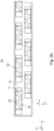
- the at least one nozzle bar 04 is arranged, for example, in at least one printing position, for example shown in 1 .
- the printing position describes that position of the nozzle bar 04 in which the nozzle bar 04 is arranged when the printing press is in a printing operating state.
- a respective print head 08 arranged in its printing position is preferably characterized in that the respective exit surface 09 is separated from the intended transport path for at least one printing substrate 03 and/or from the at least one printing substrate 03 and/or from the printing substrate guide element 02 assigned to the respective nozzle bar 04 Having a distance of at most 5 mm (millimeters), preferably at most 1.5 mm and/or at least 0.5 mm, preferably at least 1.0 mm.
- At least one printing material 03 is guided along the transport direction T by means of the at least one printing material guide element 02 through a space between the respective printing material guide element 02 and the relevant nozzle bar 04.
- the at least one print head 08, each with at least one exit surface 09, is positioned in the relevant nozzle bar 04 facing the printing material guide element 02.
- the at least one nozzle bar 04 preferably comprises at least one print head 08, in particular at least two print heads 08.
- the at least two print heads 08 are preferably arranged next to one another, in particular adjacent.
- the at least two print heads 08 are preferably next to one another along the y-direction, in particular adjacent to one another, preferably adjacent, and/or preferably partially in the x-direction overlapping, arranged.
- the individual print heads 08 of the nozzle bar 04 in question are preferably arranged along the y-direction within at least one row, preferably within at least two, in particular parallel, rows of print heads 08.
- the respective exit surfaces 09 of at least two print heads 08 arranged next to one another, preferably adjacent ones, in particular within a row, are each positioned at a distance from one another, in particular in the y direction, by the at least one positioning gap 07.
- the at least two print heads 08 arranged next to one another in the y direction are preferably arranged spaced apart from one another by the at least one positioning gap 07. More preferably, the at least two print heads 08 arranged next to one another in the y direction, in particular adjacent print heads 08, in particular the respective exit surfaces 09 of the print heads 08 arranged next to one another in particular in the y direction, delimit the corresponding positioning gap 07 in the y direction. This makes it easier, for example, to position the respective print heads 08.
- the print heads 08 of the nozzle bar 04 which are preferably arranged in a row in the y-direction, for example in the x-direction, preferably in the transport direction T, are each arranged at least partially obliquely overlapping and/or preferably the respective exit surfaces 09 of the corresponding print heads 08 are arranged spaced apart from one another in the y-direction by the respective one positioning gap 07.
- the nozzle bar 04 comprises, for example, at least two preferably parallel rows of print heads 08, one row in the y-direction comprising at least two print heads 08, preferably a large number of print heads 08.
- the print heads 08 of the rows arranged in the y-direction are preferably arranged offset from one another in the x-direction, as a result of which the respective exit surfaces 09 of the print heads 08 arranged offset from one another preferably at least partially overlap.
- the at least one printing unit 01 preferably has at least two nozzle bars 04, for example at least four nozzle bars 04.
- each nozzle bar 04 of the at least one printing unit 01 has a different pressure fluid than the other nozzle bars 04, for example a different color.
- the printing press has at least two printing units 01, each with at least one, preferably at least two, more preferably at least four, nozzle bars 04.
- at least eight different colors can be printed and/or the at least one printing substrate 03 can be printed on both the top and bottom.
- At least one nozzle bar 04 of the nozzle bars 04 preferably has cyan or magenta or yellow or black or at least one special color as the color of the printing fluid.
- the at least one nozzle bar 04 preferably has at least one print head 08, preferably at least one inkjet print head 08 and/or at least one inkjet print head.
- the at least one print head 08 preferably has the at least one exit surface 09 and preferably at least one, in particular at least two, contact surfaces 11.
- the at least one contact surface 11 is preferably designed as a spacer surface 11 .
- the contact surface 11 is preferably designed in such a way that the at least one exit surface 09 is arranged to avoid unwanted contact with components or other bodies, for example when the at least one exit surface 09 is being cleaned.
- the spacing surface 11 preferably extends over the entire extent of the respective print head 08 However, dimensions over only part of the extent of the respective print head 08 are also possible.
- the at least one exit surface 09 of the at least one print head 08 is a surface of the respective print head 08 that faces the transport path and is located in particular in a plane whose normal vector is arranged parallel to the z-direction.
- the exit surface 09 is designed, for example, as a parallelogram, preferably as a non-rectangular parallelogram.
- a further exemplary embodiment of the exit surface 09 is a trapezium, in particular an isosceles trapezium.
- the exit surface 09 preferably includes at least one opening, in particular a large number of openings, through which the printing fluid can leave at least one volume, in particular a large number of volumes, of the relevant print head 08, preferably in the form of drops.
- An exit direction of the at least one exit surface 09 is the direction in which the printing fluid exits and/or can exit the respective print head 08 through at least one opening of the corresponding exit surface 09.
- the exit direction of the exit surface 09 is preferably at least in one component and more preferably completely parallel to a surface normal of the exit surface 09 of the respective print head 08.
- the respective exit surfaces 09 of the relevant print heads 08 of a nozzle bar 04 which are arranged next to one another in the y-direction, are preferably arranged at least partially adjacent to one another in the x-direction, more preferably at least partially overlapping.
- the sum of all exit surfaces 09 within at least one row, for example at least two rows, of print heads 08 of a nozzle bar 04 arranged in the y-direction extends over the entire working width of the respective nozzle bar 04.
- Each position is therefore along a straight line in y - Direction on the transport path associated with an opening within an exit surface 09 of the nozzle bar 04 in question, through which the pressure fluid can leave a volume of a corresponding print head 08 of the nozzle bar 04.
- At least two print heads 08 in the y-direction are preferred within a nozzle bar 04 arranged side by side, in particular adjacent to one another.
- two print heads 08 are arranged adjacent to one another in the y-direction within a row of print heads 08.
- the respective exit surfaces 09 of the at least two print heads 08 are preferably arranged spaced apart from one another by the one positioning gap 07.
- the at least one positioning gap 07 preferably extends in the y-direction by a maximum of 0.5 mm (zero point five millimeters), in particular by a maximum of 0.2 mm.
- the at least one positioning gap 07 extends in the y-direction by at least 0.05 mm (zero point zero five millimeters), preferably at least 0.1 mm.
- a longitudinal direction of the at least one positioning gap 07, preferably the positioning angle 46 of the longitudinal direction of the positioning gap 07, is preferably arranged in a plane spanned by the x-direction and the y-direction.
- the longitudinal direction of the at least one positioning gap 07 is preferably that direction in which the greatest extent of the at least one positioning gap 07 occurs.
- a cleaning direction G and/or the y-direction preferably points to a longitudinal direction of the positioning gap 07 in a positive mathematical sense of rotation, i.e. counterclockwise, at a preferably level angle, in particular a positioning angle 46, of at least 50° (fifty degrees ), preferably at least 60° (sixty degrees), more preferably at least 70° (seventy degrees) and/or at most 130° (one hundred and thirty degrees), preferably at most 120° (one hundred and twenty degrees), more preferably at most 110° (one hundred and ten degrees), up.
- the longitudinal direction of the positioning gap 07 preferably has a planar angle to the cleaning direction G, in particular an opening angle 47, which is preferably an acute angle or an obtuse angle.
- the longitudinal direction of the positioning gap 07 corresponds to the longitudinal direction of the Positioning gap 07, is arranged in the plane spanned by the x-direction and the y-direction.
- the longitudinal direction of the positioning gap 07 is preferably that direction in which the greatest extent of the positioning gap 07 occurs.
- the longitudinal direction of the positioning gap 07 is preferably oriented within the plane spanned by the x-direction and the y-direction with at least one component orthogonal to the cleaning direction G.
- Positioning angle 46 thus corresponds, for example, to the at least partial oblique overlap in the x-direction of at least two print heads 08 arranged next to one another, in particular adjacent to one another.
- Positioning angle 46 preferably has an angle that is not equal to 90°.
- at least one component of the longitudinal direction of the at least one positioning gap 07 preferably within the plane spanned by the x-direction and the y-direction, has a value greater than zero, with the component being orthogonal to the y-direction and/or orthogonal to the Cleaning direction G is oriented.
- the printing machine preferably has at least one control unit.
- the at least one control unit is preferably designed to control the at least one print head 08.
- the at least one control unit is preferably connected to the at least one print head 08, at least by way of lines.
- the at least one control unit is preferably designed to control the ejection of pressurized fluid through the at least one opening within the at least one nozzle surface 09.
- At least one feed device 13 for ejecting a fluid is preferably assigned to the respective positioning gap 07.
- the at least one feed device 13 is preferably designed as a nozzle 13, in particular as a cleaning nozzle 13.
- the feed device 13 is also preferably designed as a nozzle 13 for ejecting fluid, preferably a gaseous fluid and/or compressed gas.
- the feed device 13 is arranged so that a fluid, for example a compressed gas and/or a gas mixture, in particular air, and/or a liquid can flow through the respective feed device 13 in such a way that the fluid can leave the feed device 13, in particular through an outlet opening 17, in an outlet direction L.
- At least one component of the outlet direction L is preferably directed towards the respective positioning gap 07.
- At least one feed device 13 for ejecting a fluid with an outlet direction L is preferably assigned to the respective positioning gap 07, with at least one component of the outlet direction L being directed towards the respective positioning gap 07.
- the outlet opening 17 of the feed system 13 is preferably directed towards the positioning gap 07, for example from above and/or from above the printing material guide element 02 in the direction of the printing material guide element 02.
- the feed device 13 preferably comprises at least one feed element 14 and/or at least one outlet element 16; 43, wherein the at least one outlet element 16; 43 is preferably embodied as at least one delimiting element 16 and/or at least one opening element 43, and/or the at least one outlet opening 17.
- the feed device 13 preferably has at least one cavity, which is preferably connected to the at least one outlet opening 17.
- the at least one outlet element 16; 43 each formed as at least one metal sheet or a tube.
- the delimiting element 16 is preferably flat, for example as a flat sheet metal.
- the at least one opening element 43 preferably comprises at least one cutout 17, which is more preferably configured as the at least one outlet opening 17.
- the at least one feed system 13 is preferably connected to at least one print head 08 of the respective print heads 08, which delimit the respective positioning gap 07.
- the at least one nozzle bar 04 preferably comprises the at least one Feeding device 13, wherein the feeding device 13 is preferably positioned in the z-direction on the side of the exit surface 09 that faces away from the at least one opening of the respective exit surface 09.
- the at least one nozzle bar 04 preferably includes the at least one feed device 13, with the feed device 13 preferably being arranged in the z-direction on the side facing away from the transport path of at least one exit surface 09 of at least one print head 08 of the corresponding nozzle bar 04 and/or with the respective outlet direction L of the at least one feed system 13 is directed towards at least one positioning gap 07 between two print heads 08, which are preferably adjacent in the y direction.
- the at least one feed system 13 is preferably arranged in the z-direction on the side of the respective exit surface 09 that faces away from the transport path. More preferably, the at least one feed device 13 is positioned on that side of the print head 08, in particular the exit surface 09, on which the print head 08 is attached to the corresponding nozzle bar 04. More preferably, the at least one feed device 13 is positioned such that the outlet direction L is directed from one side of the print head 08, in particular one side of the exit surface 09, onto the at least one positioning gap 07, in which the print head 08 is attached to the corresponding nozzle bar 04 .
- the feed device 13 is preferably arranged at a distance from the positioning gap 07 in the z-direction. More preferably, the feed device 13 is arranged adjacent to the positioning gap 07 in the z-direction.
- the outlet opening 17 is preferably arranged at a distance from the positioning gap 07 in the z-direction. More preferably, the outlet opening 17 is arranged adjacent to the positioning gap 07 in the z-direction.
- the feed device 13, in particular the respective outlet opening 17 is preferably arranged at a distance in the z direction from the respective exit surfaces 09 of two print heads 08, which are arranged in the y direction are arranged side by side and whose exit surfaces 09 delimit the corresponding positioning gap 07.
- the outlet direction L is preferably a direction in which a fluid, for example a gas and/or a gas mixture, in particular air, and/or a liquid, the feed device 13 in question, preferably through the at least one outlet element 16; 43, in particular the at least one outlet opening 17, can leave.
- a fluid for example a gas and/or a gas mixture, in particular air, and/or a liquid
- the feed device 13 in question preferably through the at least one outlet element 16; 43, in particular the at least one outlet opening 17, can leave.
- at least one component of the outlet direction L is parallel and/or points in an identical direction to the outlet direction of the at least one outlet surface 09 of a print head 08 of the nozzle bar 04. More preferably, at least one component of the outlet direction L is parallel and/or points in an identical direction Direction to the surface normal of the exit surface 09 of the respective print head 08 and/or a direction in which the printing fluid can leave the respective exit surface 09.
- the outlet direction L is preferably parallel to a main direction, which is preferably defined by at least one side wall of the feed device 13, which is more preferably defined by the at least one delimiting element 16.
- the outlet direction L preferably has at least one component in the z-direction, with the component in the z-direction preferably facing the transport path.
- the outlet direction L includes at least one component in the z-direction and at least one component in the x-direction, the component in the z-direction being larger than the component in the x-direction.
- the outlet direction L is preferably a direction within a plane leading to the position of the positioning gap 07 along the y-direction, for example, shifted by the z-direction and at least one direction of a shortest boundary, which is in a plane of the x-direction and y-direction is spanned, the respective exit surface 09 of the relevant print head 08, which preferably includes the positioning gap 07 is limited, expanded.
- the extent of the at least one feed device 13 in the y direction is identical to the extent of the respective positioning gap 07 in the y direction. More preferably, the at least one feed device 13 extends in the y-direction by a maximum of 0.5 mm (millimeters), in particular by a maximum of 0.2 mm. More preferably, the at least one feed device 13 extends in the y-direction by at least 0.05 mm, preferably at least 0.1 mm.
- the outlet opening 17 is preferably in the plane that runs through the z-direction and at least one direction of the shortest boundary, which is spanned in a plane in the x-direction and y-direction, of the respective exit surface 09 of the print head 08 in question, with the respective exit surface 09 delimits the positioning gap 07, is designed in such a way that the relevant outlet opening 17 has smaller dimensions in the z-direction far from the respective exit surface 09, in particular far from the transport path, than in the z-direction close to the exit surface 09, in particular close to the transport route.
- the outlet opening 17 preferably points in the plane which is displaced to the position of the positioning gap 07, for example along the y-direction, through the z-direction and at least one direction of the shortest boundary, which is spanned in a plane of the x-direction and y-direction , the respective exit surface 09 of the print head 08 in question, which delimits the positioning gap 07, is spanned into a shape that corresponds, for example, to a two-dimensional longitudinal section of a cone.
- the diameter of the outlet opening 17, measured in the direction of the shortest boundary, which is spanned in a plane in the x-direction and y-direction, of the exit surface 09, which bounds the positioning gap 07 preferably increases along the z-direction in the direction of the transport route to.
- the at least one outlet opening 17 at the point of the feed device 13, which is the smallest distance from the respective positioning gap 07 has a maximum diameter. More preferably, the maximum diameter of the corresponding outlet opening 17 is greater than the extent of the at least one exit surface 09 of the relevant print head 08, which is arranged on the corresponding positioning gap 07, in the direction of the shortest boundary of the respective exit surface 09.
- the delimiting element 16 preferably delimits the respective outlet opening 17 on one side in the y-direction.
- the respective delimiting element 16 is preferably in direct contact with the respective opening element 43.
- the feed element 14 is in direct contact with the respective opening element 43, so that there is preferably a connection between at least one cavity of the supply element 14 and the respective outlet opening 17.
- the opening element 43 and in particular the respective outlet opening 17 of the corresponding feed device 13 is arranged between the respective delimiting element 16 and the respective feed element 14 .
- the supply element 14 preferably comprises the at least one cavity, the cavity being connected to at least one source for supplying the at least one fluid, for example a gas and/or a gas mixture, in particular air, and/or a liquid, and to the outlet opening 17 .
- the at least one fluid for example a gas and/or a gas mixture, in particular air, and/or a liquid
- a fluid for example a gas and/or gas mixture and/or a liquid
- the at least one fluid in particular compressed gas, flows through the cavity of the supply element 14 and preferably meets the delimiting element 16 through the recess 17 of the opening element 43.
- the fluid for example the gas and/or the gas mixture and/or the Liquid, for example deflected in such a way that the fluid preferably flows out of the respective feed device 13 through the at least one outlet opening 17 in
- the fluid for example the gas and/or the gas mixture and/or the liquid, preferably has a pressure of at least 0.1 bar, in particular at least 0.2 bar, and at most 0.7 bar, in particular, when it exits from the feed device 13 of a maximum of 0.5 bar.
- an exit of the fluid in the exit direction L is indicated by dashed lines as an example.
- the nozzle bar 04 comprises at least one positioning guide 06, which is preferably arranged to be movable, in particular linearly movable.
- the respective nozzle bar 04 in particular the respective print heads 08 of the nozzle bar 04, can preferably be and/or can be arranged in the at least one printing position and/or at least one idle position and/or at least one maintenance position by means of the respective positioning guide 06.
- the at least one positioning guide 06 is preferably configured to arrange the at least one nozzle bar 04 in its at least one position, preferably in at least one printing position and/or in at least one maintenance position and/or in at least one rest position.
- the at least one control unit is preferably configured to control the at least one positioning guide 06.
- the at least one control unit is preferably connected, at least by cable, to the at least one positioning guide 06, preferably to at least one drive of the at least one positioning guide 06.
- the at least one nozzle bar 04 is preferably moved from the at least one printing position to the at least one idle position by moving in a direction that has a larger or maximum component in the vertical direction or the z-direction and a smaller or minimum component in the horizontal direction or into the at least one maintenance position and/or from the at least one rest position into the at least one printing position or into the at least one maintenance position and/or from the at least one maintenance position into the at least one printing position or into the at least one rest position .
- the at least one nozzle bar 04 preferably has the at least one printing position in which the at least one nozzle bar 04 is preferably arranged in a printing operating state.
- the at least one nozzle bar 04 preferably the at least one nozzle surface 09, is preferably at a distance from the transport path of printing substrate 03 of no more than 5 mm (five millimeters), preferably no more than 1.5 mm (one point five millimeters). and/or which is at least 0.5 mm (zero point five millimeters), preferably at least 1.0 mm (one point zero millimeter).
- the at least one nozzle bar 04 preferably has the at least one maintenance position.
- the at least one maintenance position is preferably a position in which the at least one print head 08 of the nozzle bar 04 in question can be serviced, for example cleaned and/or aligned, preferably without the corresponding print head 08 being removed from the nozzle bar 04 and/or the printing assembly 01 and/or to be taken from the printing machine.
- the respective maintenance position of a nozzle bar 04, in particular of the relevant print heads 08 is preferably characterized in that different nozzle bars 04 arranged in their respective maintenance positions are at different distances from one another than in their respective printing positions and/or in their respective idle positions.
- the distance between the respective exit surface 09 of a print head 08 arranged in a maintenance position and the intended transport path for at least one printing substrate 03 and/or from the at least one printing substrate 03 and/or from the printing substrate guide element 02 assigned to the respective nozzle bar 04 is preferably greater than in the corresponding print position.
- the idle position is preferably a position in which the at least one print head 08 is removed from the printing press and/or the at least one printing unit 01 and/or the at least one nozzle bar 04 and/or placed in the printing press and/or the at least one printing unit 01 and/or or the at least one nozzle bar 04 can be used.
- the operator when the operator is in the rest position, there is preferably more space available to access the at least one print head 08, while in the maintenance position there is preferably only sufficient space to be able to carry out internal, in particular automatic processes within the printing press, for example cleaning of at least one exit surface 09 of at least one print head 08.
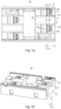
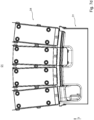
- Figure 4a shows, for example, a schematic representation of at least one printing unit 01 with a plurality of nozzle bars 04, with at least one nozzle bar 04 being arranged in the printing position and at least one nozzle bar 04 being arranged in the idle position.
- Figure 4b shows, for example, a schematic representation of a printing assembly 01 with a plurality of nozzle bars 04 according to FIG Figure 4a , wherein at least one nozzle bar 04 is arranged in a maintenance position.
- the printing press preferably has at least one cleaning device 18 .
- the at least one printing unit 01 preferably includes the at least one cleaning device 18.
- Each nozzle bar 04 of a printing unit 01 is preferably assigned at least one cleaning device 18.
- the at least one print head 08 of a nozzle bar 04 arranged in the maintenance position is assigned a cleaning device 18, which is positioned in a cleaning position via a guide system 19.
- the at least one cleaning device 18 is provided for cleaning the at least one exit surface 09 and/or the at least one contact surface 11 of the at least one print head 08 of a corresponding nozzle bar 04.
- the at least one cleaning device 18 preferably additionally or alternatively cleans the at least one positioning gap 07.
- the at least one cleaning device 18 is preferably designed to clean the at least one nozzle surface 09 and the at least one contact surface 11.
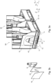
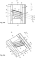
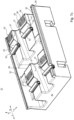
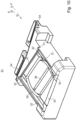
- Figure 5a shows an example of a corresponding cleaning device 18 in the cleaning position, which is preferably assigned to a nozzle bar 04 in the maintenance position. For the sake of clarity, only four print heads 08 of the relevant nozzle bar 04 are shown.
- the cleaning position of the at least one cleaning device 18 preferably corresponds to a position in which the cleaning device 18 is in direct or indirect contact with at least one, in particular one, print head 08 of the relevant nozzle bar 04 that is to be cleaned, and/or preferably a position in which the cleaning device 18 is to carry out the cleaning of the at least one print head 08 of the relevant nozzle bar 04.
- the at least one cleaning device 18 preferably has at least one guide system 19.
- the at least one cleaning device 18 is preferably movable, in particular as a whole, at least orthogonally to the transverse direction A, preferably via at least one guide system 19.
- at least one exit surface 09 of at least one print head 08 in particular one exit surface 09 of at least two, preferably at least three and more preferably at least four print heads 08, is preferably assigned to at least one cleaning device 18 and /or assignable.
- a printing unit 01 preferably comprises at least one cleaning device 18 per nozzle bar 04.
- At least two cleaning devices 18 are connected to a preferably common guide system 19 and/or are configured to be movable and/or move through the one preferably common guide system 19.
- the at least one guide system 19 preferably has at least one guide element designed, for example, as a beam and/or rod and/or rail and/or linear guide.
- the at least one cleaning device 18 is preferably designed to move and/or be movable along the at least one guide element and/or is moved, prefer to proceed in a straight line.
- the at least one cleaning device 18 is preferably arranged such that it can be moved and/or moved linearly via the at least one guide system 19, preferably by means of at least one cleaning drive.
- the at least one cleaning device 18 is preferably moved along a guide path of the at least one guide element.
- the guide path is preferably arranged along the at least one guide element in a plane whose normal vector corresponds to the transverse direction A and/or the y-direction.
- the guide path preferably has a larger component in the horizontal direction and a smaller component in the vertical direction, more preferably the guide path is horizontal.
- the at least one cleaning device 18 preferably has at least one storage position and at least one use position.
- the at least one cleaning device 18 is preferably moved along the at least one guide element from the at least one storage position into the at least one use position and/or vice versa.
- the at least one storage position of the at least one cleaning device 18 is preferably a position in which the at least one cleaning device 18 is outside the area between the at least one nozzle bar 04 and the transport path of the at least one printing substrate 03, for example defined by the at least one of the at least one nozzle bar 04 opposite printing material guide element 02, is arranged.
- the at least one cleaning device 18 is preferably arranged in the at least one storage position in the x-direction before or after the at least one nozzle bar 04.
- the at least one usage position of the at least one cleaning device 18 is preferably a position in which the at least one cleaning device 18 is within the area between the at least one nozzle bar 04 and the transport path of the at least one printing substrate 03, for example defined by the at least one of the at least one nozzle bar 04 opposite printing material guide element 02, is arranged.
- the at least one cleaning device 18 is preferably arranged in the at least one usage position during cleaning of the at least one print head 08.
- the at least one printing unit 01 preferably has the at least two nozzle bars 04.
- the at least one printing unit 01 then preferably has at least two cleaning devices 18.
- One cleaning device 18 of the at least two cleaning devices 18 is preferably assigned to one nozzle bar 04 of the at least two nozzle bars 04.
- the at least two cleaning devices 18 preferably have the at least one guide system 19, which is preferably designed as a common guide system 19.
- the at least two cleaning devices 18 are preferably moved together along the at least one guide element of the at least one common guide system 19 from their at least one use position to their at least one storage position and/or vice versa.
- the cleaning device 18 assigned to the corresponding nozzle bar 04 is preferably embodied as at least one locking element, for example in the form of at least one maintenance stop.
- the nozzle bar 04 having the corresponding print head 08 is preferably pulled and/or pressed against the cleaning device 18 by the application of a force and/or, for example, by gravity.
- the maintenance position of the at least one nozzle bar 04 is preferably clearly defined.
- the at least one cleaning device 18 preferably comprises at least one cleaning guide 44 and/or at least one cleaning drive 21 and/or at least one collecting tray 22 and/or at least one support device 23; 24 and/or at least one cleaning unit 26, preferably at least one cleaning unit 26 per row of print heads 08 in the y-direction of the relevant nozzle bar 04.
- the at least one cleaning device 18 is preferably via at least one guide system 19, preferably by means of the cleaning drive 21 preferably arranged linearly movable.
- the at least one support device 23; 24 is preferably designed as at least one positioning aid 23 and/or as at least one cleaning aid 24.
- the at least one cleaning device 18 preferably extends in the transverse direction A that is at least as large as the working width of the at least one nozzle bar 04 in the transverse direction A.
- the at least one cleaning device 18 preferably extends in the transport direction T of the printing substrate 03 which is at least as large as the working width of the at least one nozzle bar 04 in transport direction T. This means that preferably all exit surfaces 09 of all print heads 08 of the at least one nozzle bar 04 can be cleaned in one operation.
- the at least one cleaning device 18 has an extent in transport direction T that is at least as large as all the working widths of all nozzle bars 04 of printing assembly 01 in transport direction T taken together. As a result, all exit surfaces 09 of all print heads 08 of the at least one printing assembly 01 can be cleaned in one operation.
- the at least one cleaning unit 26, preferably the at least one cleaning element 31, is preferably arranged to be movable along the cleaning guide 44, for example by means of the cleaning drive 21, and/or is moved along the cleaning guide 44. More preferably, the at least one cleaning unit 26 is arranged to be movable in and/or counter to a cleaning direction G and/or is moved.
- the at least one collecting tray 22 is preferably arranged at least partially surrounding the at least one cleaning unit 26 .
- the collecting tray 22 is more preferably arranged in such a way that the collecting tray 22 at least partially encloses the cleaning unit 26 and the at least one print head 08 of the nozzle bar 04 in question that is arranged in the maintenance position.
- the at least one cleaning device 18 preferably has at least one cleaning guide 44 .
- the at least one cleaning guide 44 is preferably arranged along the longitudinal direction of the at least one cross member 22, for example within the at least one cross member 22.
- the at least one cleaning element 31 is preferably arranged such that it can move and/or move along the longitudinal direction of the at least one cross member 22 and/or preferably along the at least one cleaning guide 44, for example driven by at least one cleaning drive.
- the at least one cleaning drive is preferably controlled by the at least one control unit of the printing press.
- the at least one cleaning element 31 is preferably arranged to be movable in and/or counter to the cleaning direction G and/or is moved.
- the cleaning direction G is preferably the direction in which an element cleaning the at least one print head 08, preferably the at least one cleaning element 31, passes this at least one print head 08.
- the cleaning direction G is preferably a direction G in which the at least one cleaning element 31 of the at least one cleaning device 18 is arranged to be movable and/or is designed to move, preferably for carrying out a cleaning step.
- the cleaning direction G is preferably horizontal.
- the cleaning direction G preferably has at least one component which is arranged parallel to the transverse direction A and/or parallel to the y-direction and is preferably oriented opposite to the y-direction.
- the cleaning direction G is arranged parallel to the transverse direction A and/or parallel to the y-direction and is preferably oriented opposite to the y-direction.
- the cleaning direction G is preferably oriented orthogonally to at least one transport direction T provided for transporting at least one printing substrate 03 and/or orthogonally to the x-direction.
- the at least one cleaning unit 26 and more preferably at least one cleaning element 31 is preferably arranged such that it can be moved in and/or counter to the cleaning direction G.
- the at least one cleaning unit 26 is preferred and the at least one cleaning element 31 is more preferred arranged to be movable at least in the cleaning direction G during a cleaning process for cleaning at least one exit surface 09 of at least one print head 08.
- the cleaning device 18 preferably has the at least one cleaning element 31 .
- the at least one cleaning unit 26 preferably comprises at least one mounting element 28, preferably at least two mounting elements 28, and/or at least one power element 29 and/or at least one carrier 27 and/or the at least one cleaning element 31.
- the at least one mounting element 28 is preferred at least two assembly elements 28 and/or the at least one force element 29 and/or the at least one carrier 27 and/or the at least one cleaning element 31 within the corresponding cleaning unit 26, preferably firmly connected to one another.
- the at least one assembly element 28, in particular the at least two assembly elements 28, are preferably in direct contact with the at least one force element 29.
- the at least one force element 29 is designed, for example, as a bellows and/or hollow body and/or spring and is preferred in terms of its expansion and/or or dimensions adjustable in the z-direction, preferably in a direction whose main component corresponds to the z-direction.
- the at least one carrier 27 is preferably embodied as a base body and/or preferably carries the at least one assembly element 28, preferably at least two assembly elements 28, and/or the at least one force element 29 and/or the at least one cleaning element 31 of the corresponding cleaning unit 26 the at least one cleaning element 31 is arranged in direct contact with at least one mounting element 28.
- the extent and/or dimensions of the cleaning unit 26 in the z-direction can preferably be adjusted by changing the extent and/or dimensions of the at least one force element 29 of the cleaning unit 26 in question and/or changeable and/or movable.
- This mobility means that the at least one cleaning element 31 can preferably be brought into contact with other components and/or removed from contact, with the at least one print head 08 and/or the at least one support device 23; 24 come into question.
- the at least one cleaning unit 26 comprises the at least one cleaning element 31, which is connected to the at least one carrier 27 via the at least one force element 29, preferably via at least four force elements 29, for example via exactly four force elements 29.
- the at least one force element 29, in particular the at least four force elements 29, is preferably designed as a spring.
- the at least one cleaning element 31 is preferably mounted and/or fixed in the at least one carrier 27, which is preferably designed as a base body, by the at least one force element 29, preferably in a floating manner.
- the cleaning device 18 preferably has at least one positioning aid 23 that is different from each print head 08, which preferably has at least one contact surface that is oriented in the same direction as the at least one contact surface 11 and/or exit surface 09 of the at least one print head 08 the at least one contact surface of the positioning aid 23, preferably adjacent to or spaced apart from the at least one contact surface 11 of a relevant print head 08 with respect to the cleaning direction G. More preferably, the contact surface of the positioning aid 23 in the z-direction has an identical component to the exit surface 09 of one with the corresponding cleaning element 31 too cleaning print head 08.
- the contact surface of the positioning aid 23 is oriented in the same direction as the at least one exit surface 09.
- the cleaning element 31 is preferably embodied as a contact element, for example as a wiper.
- the contact surface of the positioning aid 23 is oriented in the same direction as the at least one contact surface 11, in particular the at least one spacer surface 11
- the at least one positioning aid 23 is preferably arranged in such a way that the at least one cleaning element 31 is arranged so that it can be clearly positioned relative to at least one print head 08, in particular that is to be cleaned.
- the cleaning device 18 preferably comprises at least one cleaning aid 24.
- the cleaning aid 24 is preferably designed in such a way that the at least one cleaning element 31 can be cleaned.
- the cleaning aid 24 preferably has at least one spray device and/or at least one wiping device.
- the at least one cleaning device 18 preferably has at least one sealing element 56, for example at least one sealing lip.
- the at least one sealing element 56 is arranged within at least one traverse 22 of the at least one cleaning device 18 .
- the at least one cleaning device 18 is preferably in the at least one usage position while the at least one nozzle surface 09 of the at least one print head 08 is being sealed with the at least one sealing element 56, i.e. when there is direct contact between the at least one sealing element 56 and the at least one print head 08 arranged.
- the at least one nozzle bar 04 is preferably lowered onto the at least one cleaning device 18, for example from the at least one maintenance position.
- the at least one sealing element 56 with the at least one print head 08 and at least one delimitation unit configured, for example, as a support 57 forms an at least partially closed spatial area, preferably configured as a preservation area.
- the preservation area preferably includes an atmosphere containing at least one preservation medium.
- the at least one preservation medium preferably has at least air enriched with water and/or air enriched with compressed fluid.
- the preservation area is flushed and/or flooded with at least one fluid, for example air and/or air enriched with water, for example, and/or cleaning agent and/or pressurized fluid.
- This atmosphere is preferably designed to be gentle on the at least one nozzle surface 09 and protects the printing fluid of the at least one print head 08 from drying out.
- the at least one sealing element 56 is preferably configured to seal all print heads 08 of the at least one row of print heads 08 together. For example, the at least one print head 08 is lowered onto the at least one sealing element 56.
- the at least one cleaning device 18 preferably has the at least one cleaning element 31 .
- the at least one cleaning element 31 is preferably designed to clean the at least one nozzle surface 09.
- the nozzles of the nozzle surface 09 are thus advantageously cleaned so that there is no blockage and/or no change in the cross section of the respective nozzle, for example due to dried pressure fluid and/or dirt.
- the at least one cleaning element 31 preferably additionally or alternatively cleans the at least one contact surface 11 educated. Dirt and/or pressurized fluid is thus advantageously removed from the at least one contact surface 11 .
- substances that impede the guidance of the at least one cleaning element 31 along the cleaning direction G, in particular pressurized fluid and/or dirt are removed.
- pressurized fluid and/or dirt can get from the at least one contact surface 11 onto the at least one nozzle surface 09, for example as a result of the movement of the at least one cleaning element 31 and/or as a result of air turbulence and/or other external influences.
- Printing fluid and/or dirt remaining on the at least one contact surface 11 can also be transferred to a printing substrate 03 in an uncontrolled manner during the printing operation.
- the at least one cleaning element 31 is preferably additionally or alternatively designed to clean the at least one positioning gap 07.
- printing fluid and/or dirt can get out of the at least one positioning gap 07 onto the at least one nozzle surface 09 or escape uncontrolled from the positioning gap 07 during printing operation, for example due to the movement of the at least one cleaning element 31 and/or due to air turbulence and/or other external factors influences.
- cleaning the at least one positioning gap 07 these risks are advantageously removed before the at least one print head 08 is damaged and/or before the quality of the printed image produced deteriorates.
- the at least one cleaning element 31 is preferably embodied as a cleaning head 31.
- the cleaning element 31 is preferably firmly connected to the at least one mounting element 28 and/or the at least one carrier 27 of the cleaning device 18 in question, in particular the cleaning unit 26 in question.
- the at least one cleaning element 31 is preferably arranged such that it can be moved in and/or counter to the cleaning direction G.
- the at least one is preferred Cleaning element 31 is designed to clean all nozzle surfaces 09 and/or contact surfaces 11 and/or positioning gaps 07 of the at least two print heads 08, which are arranged in the at least one row.
- the at least one cleaning element 31 can be moved and/or is moved in the cleaning direction G and/or counter to the cleaning direction G for cleaning.
- At least one cleaning agent and/or cleaning fluid preferably refers to a liquid that is used to clean individual components of the printing press, preferably to clean the at least one nozzle surface 09 of the at least one print head 08.
- the cleaning agent is preferably used to remove soiling, for example dried coating material such as printing ink or ink and/or parts of a printing material such as paper fibers and/or dust and/or the like and/or mixtures of the substances mentioned.
- the at least one cleaning agent has water and/or at least one surfactant and/or at least one solvent.
- the at least one cleaning agent has pressurized fluid, which preferably contains no pigments.
- the at least one cleaning fluid is preferably designed to at least partially dissolve the pressure fluid of the at least one nozzle bar 04.
- the at least one cleaning element 31 preferably has at least one sliding surface 32.
- the at least one sliding surface 32 preferably has a greater extent in the cleaning direction G than orthogonally to the cleaning direction G.
- the at least one sliding surface 32 is preferably designed for direct contact with the at least one print head 08.
- the at least one cleaning element 31 is preferably designed to come into direct contact with the at least one contact surface 11 of the at least one print head 08 by means of the at least one sliding surface 32 when the latter is arranged in a cleaning position.
- the at least one sliding surface 32 When the at least one cleaning element 31 is positioned against the at least one print head 08 or vice versa and/or when the at least one cleaning element 31 moves in or counter to the cleaning direction G, the at least one sliding surface 32, preferably all sliding surfaces 32, is in contact, preferably direct contact, with the at least one contact surface 11.
- the at least one sliding surface 32 is preferably arranged orthogonally to the cleaning direction G in front of or behind the at least one nozzle surface 09, i.e. preferably arranged laterally.
- the surface of the at least one sliding surface 32 is preferably arranged in one plane.
- the plane is preferably spanned by the x-direction and the y-direction.
- the plane is preferably arranged parallel to a plane of the surface of the at least one contact surface 11 of the at least one print head 08, in particular when the at least one cleaning element 31 is placed against the at least one print head 08.
- the cleaning element 31 has a higher coordinate in the z direction in the area of the at least one sliding surface 32 than in the area of the at least one cleaning area 37, preferably at least in the area of the at least one fluid supply 38, in particular its boundary 71.
- the boundary preferably has 71 of the at least one fluid supply 71 in the z-direction at a distance from the surface of the at least one sliding surface 32.
- the at least one nozzle surface 09 is advantageously protected against direct contact with the cleaning element 31. This advantageously ensures that the at least one nozzle surface 09 is not damaged by the at least one cleaning region 37, in particular the at least one fluid supply 38.
- the at least one cleaning element 31 has at least two sliding surfaces 32.
- the at least one cleaning element 31 preferably has at least two sliding surfaces 32 which are arranged one behind the other orthogonally to the cleaning direction G, that is to say next to one another in the cleaning direction G.
- Preferred the at least two sliding surfaces 32 arranged one behind the other orthogonally to the cleaning direction G are arranged spaced apart from one another by the at least one cleaning region 37 .
- the distance between the at least two sliding surfaces 32 arranged one behind the other orthogonally to the cleaning direction G preferably corresponds to the distance between two contact surfaces 11 arranged one behind the other orthogonally to the cleaning direction G of the at least one print head 08.
- the at least two sliding surfaces 32 of the cleaning element 31, which are arranged next to one another in the cleaning direction G, are preferably at the same distance from one another as two contact surfaces 11 of a print head 08 that are spaced apart from one another in the x-direction.
- the at least two sliding surfaces 32 of the cleaning element 31, which are arranged next to one another in the cleaning direction G, are preferably spaced at least as far apart as the length of a nozzle surface 09 in the x-direction. This advantageously ensures that the at least one nozzle surface 09 does not come into direct contact with at least one of the sliding surfaces 32 and is damaged by it.
- the distance between the at least two sliding surfaces 32 arranged one behind the other orthogonally to the cleaning direction G is less than 50 mm (fifty millimeters), preferably less than 45 mm (forty-five millimeters), more preferably less than 40 mm (forty millimeters), more preferably less than 38 mm (thirty-eight millimeters).
- the at least two sliding surfaces 32 arranged next to one another in the cleaning direction G prevent the at least one cleaning element 31 from tilting and/or canting to the side and/or these sliding surfaces 32 stabilize the at least one cleaning element 31 in the direction orthogonal to the cleaning direction G.
- the at least one sliding surface 32 is preferably orthogonal to the cleaning direction G in front of or behind the at least one exit surface 09, for example spaced apart from the at least one exit surface 09 orthogonally to the cleaning direction G, so preferably arranged laterally.
- the at least one cleaning element 31 preferably has the at least two sliding surfaces 32 which are arranged one behind the other in the cleaning direction G.
- the at least two sliding surfaces 32 which are arranged one behind the other in the cleaning direction G, are spaced apart from one another by a distance greater than zero.
- the at least one sliding surface 32 preferably has a greater extent in the cleaning direction G than orthogonally to the cleaning direction G.
- These at least two sliding surfaces 32 are preferably arranged in alignment with one another in relation to the cleaning direction G.
- the at least two sliding surfaces 32 arranged one behind the other in the cleaning direction G prevent the at least one cleaning element 31 from tipping and/or canting in the cleaning direction G and/or these sliding surfaces 32 stabilize the at least one cleaning element 31 in the cleaning direction G.
- the points on the surface of the at least one cleaning element 31, which are arranged downstream of the at least one second fluid discharge 41, counter to the cleaning direction G, are preferably at a distance from the plane of the surface of the at least one sliding surface 32, preferably greater than zero.
- the at least one cleaning element 31 preferably has the at least one sliding surface 32, preferably the at least two sliding surfaces 32, counter to the cleaning direction G only, preferably exclusively, in front of the at least one second fluid outlet 41.
- the at least one sliding surface 32 is preferably designed to come into direct contact with the at least one contact surface 11 counter to the cleaning direction G only in front of the at least one second fluid discharge 41 .
- no part of the at least one sliding surface 32 preferably the at least two sliding surfaces 32, and/or no further sliding surface 32 is arranged downstream of the at least one second fluid discharge 41, counter to the cleaning direction G. More preferred are the points on the surface of the at least one cleaning element 31, which are opposite to the cleaning direction G are arranged after the at least one second fluid discharge 41, are arranged in the z-direction below the plane of the surface of the at least one sliding surface 32.
- the at least one cleaning element 31 is preferably designed to come into direct contact with the at least one contact surface 11 of the at least one print head 08 by means of the at least one sliding surface 32 when the latter is arranged in a cleaning position.
- the at least one sliding surface 32 is preferably designed to come into direct contact with the at least one contact surface 11 counter to the cleaning direction G only in front of the at least one second fluid discharge 41 .
- cleaning agent and/or pressurized fluid and/or dirt is preferably not entrained along the at least one sliding surface 32 .
- This preferably prevents cleaning agent and/or pressure fluid and/or dirt from drying on the at least one sliding surface 32, which for example has a negative effect on the sliding function and/or is difficult to remove.
- the at least one cleaning device 18 is designed to clean the at least two rows of print heads 08 of the at least one nozzle bar 04, preferably simultaneously and/or in parallel.
- the at least one cleaning element 31 is designed to clean the at least two rows of print heads 08, or there are at least two cleaning elements 31 which each clean at least one row of the at least two rows of print heads 08.
- the at least one nozzle bar 04 is preferably arranged in the at least one maintenance position for cleaning.
- the at least one cleaning device 18 is preferably arranged in the at least one usage position for cleaning.
- the cleaning head 31 is in direct or indirect contact with the at least one print head 08, then, for example, at least one cleaning fluid, in particular a cleaning agent, can be dispensed from the at least one fluid supply 38 in the immediate vicinity of the exit surface 09 of the at least one print head 08 and/or of a positioning gap 07 and through the at least one fluid discharge opening 39; 41 can also be sucked off again in the immediate vicinity of the exit surface 09 of the at least one print head 08 and/or a positioning gap 07.
- at least one cleaning fluid in particular a cleaning agent
- the cleaning head 31 is preferably brought so close to the at least one print head 08 that a cleaning gap is formed between the cleaning head 31 on the one hand and the exit surface 09 of the print head 08 on the other hand, through which the fluid, in particular the cleaning liquid, flows and thus the exit surface 09 of the at least one print head 08 and/or a positioning gap 07 is cleaned and/or is possible to clean.
- the cleaning head 31 preferably has the at least one cleaning area 37 .
- the at least one cleaning area 37 preferably has the at least one fluid supply 38 and the at least one fluid discharge opening 39; 41 on.
- the cleaning area 37 more preferably has the at least one fluid inlet 38 and/or the at least one fluid outlet 39 and/or the at least one fluid suction 41.
- the at least one fluid discharge opening 39; 41 each connected to at least one sink for removing cleaning agents and/or dirt and/or particles, for example.
- the at least one fluid supply 38 is preferably connected to a source of cleaning agent.
- the fluid supply 38 is preferably designed as a fluid supply opening 38 within the cleaning area 37 .
- the at least one cleaning area 37 is preferably that area of the surface of the at least one cleaning element 31 which has the at least one fluid inlet 38 and the at least one fluid outlet opening 39; 41 included.
- the components of the at least one cleaning area 37 are preferably at a distance greater than zero from the at least one print head 08, in particular from its nozzle surface 09 and/or from its at least one contact surface 11, when the at least one cleaning element 08 is placed against the at least one print head 08 is.
- the surface of the at least one cleaning area 37 is preferably at a distance greater than zero from the at least one print head 08, in particular from its nozzle surface 09 and/or from its at least one contact surface 11, preferably permanently spaced.
- the components of the at least one cleaning area 37 are preferably designed to come into indirect contact with the at least one print head 08, in particular with its nozzle surface 09 and/or with its at least one contact surface 11, during the cleaning process.
- the at least one cleaning head 31 preferably has at least one ramp 33; 34 on. More preferably, the cleaning head 31 has at least one first ramp 33 and at least one second ramp 34 .
- the at least one cleaning element 31 can preferably be arranged in at least one first position and/or in at least one second position, the first position of the cleaning element 31 being arranged at a distance from the second position of the cleaning element 31, preferably along the cleaning direction G.
- the at least one print head 08 and/or the at least one cleaning head 31 has at least one guide device 36.
- This guide device 36 is preferably designed as a guide surface 36 whose surface normal has at least one component that is orthogonal to the z-direction and to the cleaning direction G.
- the at least one guide device 36 is preferably arranged in such a way that the cleaning head 31 can be positioned within a tolerance range or in an exact position with respect to a direction oriented parallel to the x-direction and/or orthogonal to the cleaning direction G and orthogonal to the z-direction and/or is positioned.
- the at least one guide surface 36 of a cleaning head 31 preferably borders directly on at least one sliding surface 32 of the respective cleaning head 31.
- the at least one sliding surface 32 is spaced apart from the at least one guide surface 36, preferably with at least one further surface in between.
- the at least one additional surface is parallel to the at least one sliding surface 32.
- the at least one additional surface is preferably spaced apart from the plane of the surface of the at least one sliding surface 32, for example arranged below in the z-direction, preferably by at least 0.1 mm (zero point one millimeter) and/or by a maximum of 0.2 mm (zero point two millimeters) from the plane of the surface of the at least one sliding surface 32.
- At least one ramp 33 is preferably located opposite to the cleaning direction G in front of the at least one cleaning area 37, preferably in front of the at least one fluid inlet 38 and/or in front of the at least one fluid outlet 39; 41, arranged.
- the at least one first ramp 33 is preferably a first part of the surface of the cleaning element 31 that comes into view.
- the at least one first ramp 33 is preferably designed as an entry ramp 33 .
- the first ramp 33 preferably has a positive gradient, starting from an outer point of the at least one cleaning element 31 to its at least one cleaning region 37 .
- the first ramp 33 is preferably arranged to reduce the distance between a reference point of the at least one print head 08 to be cleaned and the surface of the at least one cleaning element 31 facing it, in particular when the at least one cleaning element 31 moves in cleaning direction G.
- the first ramp 33 has a positive gradient starting from an outer point of the at least one cleaning element 31 to its at least one cleaning region 37.
- the reference point of the first ramp 33 is preferably a point on the first ramp 33 which is arranged perpendicular to the print head 08 to be cleaned.
- the first ramp 33 is preferably at a first distance from a print head 08 to be cleaned, preferably from at least one exit surface 09 and/or spacing surface 11 to be cleaned, at the reference point of the first ramp 33.
- the first ramp 33 is preferably at a second distance from a print head 08 to be cleaned, preferably from at least one exit surface 09 and/or spacer surface 11 to be cleaned, at the reference point of the first ramp 33, the second distance between the reference point of the first ramp 33 and the print head 08 to be cleaned is less than the first Distance between the reference point of the first ramp 33 and the print head 08 to be cleaned.
- a first point of the at least one first ramp 33 near the at least one fluid supply 38 preferably has a first distance to the at least one nozzle surface 09 and/or to the at least one contact surface 11 of the at least one print head 08, while a second point of the at least one first ramp 33 remote from the at least one fluid supply 38 is preferably a second distance from the at least one nozzle surface 09 and/or from the at least one contact surface 11 of the at least one print head 08.
- the first distance is preferably less than the second distance.
- At least one ramp 34 is located opposite to the cleaning direction G after the at least one cleaning area 37, preferably after the at least one fluid inlet 38 and/or after the at least one fluid outlet 39; 41, arranged.
- the at least one second ramp 34 is preferably a part of the surface of the cleaning element 31 that comes into view after the at least one cleaning area 37 .
- the at least one second ramp 34 is preferably designed as an outlet ramp 34 .
- the second ramp 34 preferably has a positive gradient, starting from an outer point of the at least one cleaning element 31 to its at least one cleaning region 37 .
- the second ramp 34 is preferably arranged to increase the distance between a reference point of the at least one print head 08 to be cleaned and the surface of the at least one cleaning element 31 facing it, in particular when the at least one cleaning element 31 moves in cleaning direction G.
- the second ramp 34 is preferred arranged to increase the distance between a reference point of the second ramp 34 and the print head 08 to be cleaned.
- the second ramp 34 preferably has a positive gradient, starting from an outer point of the at least one cleaning element 31 to its at least one cleaning region 37 .
- the reference point of the second ramp 34 is preferred a point of the second ramp 34, which is arranged perpendicular to the print head 08 to be cleaned.
- the second ramp 34 preferably has a first spacing at the reference point of the second ramp 34 from a print head 08, in particular one that is to be cleaned, preferably from at least one exit surface 09 and/or spacing surface 11 that is to be cleaned.
- the second ramp 34 is preferably at a second distance from a print head 08, in particular one to be cleaned, preferably from at least one exit surface 09 and/or spacer surface 11 to be cleaned, at the reference point of the second ramp 34, whereby the second distance between the reference point of the second ramp 34 and print head 08, in particular to be cleaned, is greater than the first distance between the reference point of the second ramp 34 and print head 08, in particular to be cleaned.
- a first point of the at least one second ramp 34 near the at least one fluid supply 38 is preferably at a first distance from the at least one nozzle surface 09 and/or from the at least one contact surface 11 of the at least one print head 08, while a second point of the at least one second ramp 34 remote from the at least one fluid supply 38 preferably a second distance from the at least one nozzle surface 09 and/or from the at least one contact surface 11 of the at least one print head 08.
- the first distance is preferably less than the second distance.
- the at least one cleaning area 37 is preferably arranged between the at least one first ramp 33 and the at least one second ramp 34 .
- the at least one first ramp 33 is arranged opposite to the cleaning direction G in front of the at least one cleaning area 37.
- the at least one second ramp 34 is preferably arranged downstream of the at least one cleaning area 37, counter to the cleaning direction G.
- the first ramp 33 preferably rises from an outer edge of the cleaning element 31 towards the at least one cleaning region 37 .
- the second ramp 33 preferably rises from an outer edge of the cleaning element 31 towards the at least one cleaning region 37 .
- the gradients of the first ramp 33 and the second ramp 34 are preferably directed in opposite directions to one another.
- the at least one cleaning element 31 has at least one edge 51, preferably at least one tear-off edge.
- This at least one edge 51 is preferably arranged counter to the cleaning direction G between the at least one cleaning region 37 and a rear boundary of the at least one cleaning element 31.
- the at least one edge 51 is preferably arranged counter to the cleaning direction G between the at least one second fluid outlet 41 and a rear boundary of the at least one cleaning element 31.
- the surface of the at least one cleaning element 31 preferably points counter to the cleaning direction G downstream of the at least one cleaning area 37, preferably downstream of the at least one first fluid outlet 39, more preferably downstream of the at least one second fluid outlet 41, more preferably downstream of the last cleaning fluid and/or Dirt and / or pressurized fluid sucking unit, a reduced height compared to the height of the surface of the at least one cleaning area 37.
- the at least one cleaning area 37 preferably has at least the at least one fluid supply 38.
- the surface of the at least one cleaning element 31 following the at least one cleaning area 37 is preferably lower in the vertical direction, in particular in the z-direction, than the surface of the at least one cleaning area 37.
- the at least one cleaning area 37 is preferably opposite a surface in the z-direction of the cleaning element 31 towards the at least one edge 51, in particular in the z-direction compared to the at least one second ramp 34.
- the at least one sliding surface 32 is preferably configured to come into direct contact with the at least one contact surface 11 counter to the cleaning direction G only in front of the at least one second fluid outlet 41, in particular due to the at least one edge 51 or second ramp 34.
- the distance between the surface of the at least one cleaning element 31 and the surface of the at least one print head 08 facing it, opposite to cleaning direction G, in front of edge 51 is preferably smaller than the distance between the surface of the at least one cleaning element 31 and the surface of the at least one print head 08 facing it, counter to the cleaning direction G after edge 51.
- the distance between the surface of the at least one cleaning element 31 and the surface of the at least one print head 08 facing it increases counter to the Cleaning direction G after the edge 51 by at least 5%, preferably at least 10%, and/or by a maximum of 30%, preferably a maximum of 20%, compared to the distance between the surface of the at least one cleaning element 31 and the surface of the at least one print head 08 facing it against the cleaning direction G in front of the edge 51.
- the at least one edge 51 is arranged in the cleaning direction G after the at least one cleaning area 37, in particular after the at least one fluid suction device 41, and/or in front of the at least one second ramp 34.
- the at least one edge 51 prevents smearing of pressurized fluid that is located on the at least one exit surface 09 at this point in time, preferably when the at least one cleaning element 31 is passing the exit surface 09 in question.
- Downstream of the cleaning direction G the distance between the surface of the at least one cleaning element 31 and the surface of the at least one print head 08 facing the at least one cleaning area 37, in particular downstream of the second fluid outlet 41, is preferably larger than in the area of the at least one cleaning area 37.
- the at least one edge 51 to the at least one second fluid outlet 41 is at a distance of no more than 10%, preferably no more than 5%, of the length of the at least one cleaning element 31 in the cleaning direction G.
- the at least one edge 51 preferably also extends over the area of the at least one sliding surface 32.
- the at least one edge 51 does not carry cleaning agent and/or pressurized fluid and/or dirt along the at least one sliding surface 32. This preferably prevents cleaning agent and/or pressure fluid and/or dirt from drying on the at least one sliding surface 32, which for example has a negative effect on the sliding function and/or is difficult to remove.
- the at least one cleaning region 37 preferably has an area of at least 20% (twenty percent), preferably at least 30% (thirty percent), relative to the area generated by the expansion of the at least one cleaning element 31 in the cleaning direction G and orthogonal to the cleaning direction G. more preferably at least 45% (forty-five percent), and/or at most 80% (eighty percent), preferably at most 70% (seventy percent), more preferably at most 65% (sixty-five percent), of the surface of the at least one cleaning element 31 on.
- the at least one cleaning area 37 in the surface of the at least one cleaning element 31 preferably has an area of at least 600 mm 2 (six hundred square millimeters), preferably at least 800 mm 2 (eight hundred square millimeters), more preferably at least 1000 mm 2 (one thousand square millimeters), and/ or at most 1800 mm 2 (one thousand eight hundred square millimeters), preferably at most 1600 mm 2 (one thousand six hundred square millimeters), more preferably at most 1400 mm 2 (one thousand four hundred square millimeters).
- the cleaning head 31 preferably has the at least one fluid supply 38 and the at least one fluid discharge opening 39; 41, preferably within the at least one cleaning area 37.
- the at least one fluid supply 38 is more preferably designed as at least one fluid supply 38 for supplying cleaning liquid.
- the at least one fluid discharge opening 39; 41 is more preferred than at least one fluid discharge opening 39; 41 designed for cleaning liquid and / or dirt.
- the cleaning head 31 has the at least two fluid discharge openings 39; 41, wherein in each case a first fluid discharge opening 39 is preferably designed as a fluid discharge 39 and/or wherein in each case a second fluid discharge opening 41 is preferably designed as a fluid suction device 41.
- the at least one first fluid discharge opening 39 preferably at least partially, more preferably completely, surrounds the at least one fluid supply 38 in one plane, particularly as viewed in a plan view of the cleaning element 31.
- the at least one cleaning element 31 preferably has the at least one fluid supply 38 with at least one outlet opening for cleaning fluid.
- the at least one outlet opening is preferably also referred to as a fluid supply opening 38 .
- the at least one fluid supply 38 is preferably connected to a source of cleaning agent.
- the at least one outlet opening of the at least one fluid supply 38 is preferably arranged within the at least one cleaning area 37 .
- Cleaning agent is preferably expelled through the at least one outlet opening of the fluid supply 38 .
- the cleaning agent then preferably comes into direct contact with the at least one nozzle surface 09 and/or the at least one positioning gap 07 and/or the at least one contact surface 11 and wets them.
- the at least one fluid supply 38 is preferably designed to wet the at least one contact surface 11 with cleaning fluid.
- At least one boundary 71 of the at least one outlet opening of the at least one fluid supply 38 is preferably arranged in the plane of the at least one cleaning area 37.
- the boundary 71 is the outermost edge of the at least one fluid supply 38.
- the at least one boundary 71 of the at least one outlet opening is preferably elongated and/or oval and/or slot-shaped and/or designed as a groove and/or in a shape other than circular .
- a groove preferably has at least two mutually parallel longitudinal sides.
- a tangential line through the first boundary point of the boundary 71 of the outlet opening of the at least one fluid supply 38 is preferably parallel to the longitudinal direction.
- a straight line through at least two centroids of the area of the at least two outlet openings preferably describes the longitudinal direction of the at least one fluid supply 38.
- the fluid supply opening 38 in particular the at least one outlet opening of the fluid supply 38, preferably has the at least one delimitation 71 of the fluid supply opening 38 in a plane of the surface of the cleaning region 37, preferably orthogonal to the z-direction, with a centroid. More preferably, the boundary 71 of the fluid supply opening 38 has at least one first boundary point, which is arranged in alignment with the centroid with respect to the cleaning direction G.
- the delimitation 71 of the fluid supply opening 38 preferably has at least one second delimitation point, which is arranged in alignment with the centroid with respect to a direction orthogonal to the cleaning direction G.
- the delimitation 71 of the fluid supply opening 38 preferably has at least one third delimitation point, which is arranged on the delimitation of the fluid supply opening 38 in an extension of a distance from the first delimitation point to the centroid of the area.
- the delimitation 71 of the fluid supply opening 38 preferably has at least a fourth delimitation point, which is arranged on the delimitation of the fluid supply opening 38 in an extension of a distance from the second delimitation point to the centroid of the area.
- the respective first delimitation point and the second delimitation point and the third delimitation point and the fourth delimitation point are preferably at a distance greater than zero positioned spaced apart on the boundary 71 of the fluid supply port 38 .
- the distance between the first delimitation point and the third delimitation point on the delimitation 71 of the fluid supply opening 38 is preferably less than the distance between the second delimitation point and the fourth delimitation point on the delimitation 71 of the fluid supply opening 38.
- a longitudinal direction of the fluid supply opening 38 is preferably at least partially orthogonal to a straight line between the first delimitation point and the center of gravity of the delimitation of the fluid supply opening 38.
- the at least one fluid supply opening 38 in particular the delimitation 71 of the fluid supply opening 38, points in the plane spanned by the x-direction and the y-direction, and/or or orthogonal to the z-direction, preferably the longitudinal direction of the fluid supply opening 38 and a transverse direction of the fluid supply opening 38 .
- the expansion of the fluid supply opening 38 in its longitudinal direction and in its transverse direction is preferably different from one another.
- the fluid supply opening 38, in particular the delimitation 71 of the fluid supply opening 38 preferably has a maximum extension in its longitudinal direction.
- the extension of the fluid supply opening 38, in particular the delimitation 71 of the fluid supply opening 38 is preferably smaller in the transverse direction of the fluid supply opening 38 than in its longitudinal direction.
- a cleaning area 37 has at least two fluid supply openings 38 each with a delimitation 71 of the respective fluid supply opening 38 in a plane of the surface of the cleaning area 37 .
- the at least two fluid supply openings 38 each have a centroid, with the centroids of the fluid supply openings 38 preferably being arranged on a straight line.
- the straight line of the at least two centroids of the fluid supply openings 38 is preferably arranged at least partially orthogonally to the cleaning direction G and orthogonally to the z-direction.
- a tangent line through the first boundary point of boundary 71 of fluid supply opening 38 is preferably at least partially orthogonal to the Cleaning direction G and orthogonal to the z-direction.
- the tangent through the first boundary point of the boundary 71 of the fluid supply opening 38 to the cleaning direction G in a positive mathematical sense of rotation, i.e. counterclockwise has a planar angle of at least 50°, preferably at least 60°, and at most 130° , preferably of at most 120°.
- the tangential through the first boundary point of the boundary of the fluid supply opening 38 is preferably parallel to a plane which is displaced to the position of the positioning gap 07, for example along the y-direction, through the z-direction and at least one direction of the shortest boundary 71 of a respective exit surface 09, which is spanned in a plane in the x-direction and y-direction of the print head 08 to be cleaned of the relevant nozzle bar 04, which delimits the positioning gap 07.
- the tangential through the first boundary point of boundary 71 of fluid supply opening 38 is preferably parallel to a longitudinal direction of fluid supply opening 38, in particular in the case of a fluid supply opening 38 which, for example, is elongated and/or oval and/or slot-shaped and/or as a groove and/or in another Shape is designed as circular. More preferably, the longitudinal direction of the fluid supply opening 38 is aligned parallel to at least one positioning gap 07 of the associated nozzle bar 04. The longitudinal direction of the fluid supply opening 38 is preferably located in a plane spanned by the x-direction and the y-direction.
- the fluid supply opening 38 is preferably designed as a groove and/or elongated and/or oval and/or slot-shaped, preferably in the plane orthogonal to the z-direction.
- a groove preferably has at least two mutually parallel longitudinal sides.
- the longitudinal direction of the at least one fluid supply 38 has a preferably planar angle to the cleaning direction G, in particular an opening angle 47, which is preferably acute-angled or obtuse-angled.
- the longitudinal direction of the at least one fluid supply 38 preferably points to the cleaning direction G in a positive mathematical direction of rotation, which means counterclockwise preferably a flat angle, in particular an opening angle 47 of at least 50° (fifty degrees), preferably at least 60° (sixty degrees), more preferably at least 70° (seventy degrees) and/or at most 130° (one hundred and thirty degrees), preferably at most 120° (one hundred and twenty degrees), more preferably at most 110° (one hundred and ten degrees).
- the opening angle 47 is 106° (one hundred and six degrees).
- the opening angle 47 is preferably not equal to 90° (ninety degrees).
- the longitudinal direction of the at least one fluid supply 38 is inclined relative to the cleaning direction G.
- the inclined position of the at least one fluid supply 38 preferably corresponds to an at least partial oblique overlap of the at least two print heads 08 of the at least one row.
- This preferably enables cleaning agent to penetrate optimally into the at least one positioning gap 07.
- this means, for example, that the longitudinal direction of the at least one fluid supply opening 38 is at an identical angle to the longitudinal direction of the at least one positioning gap 07, preferably by the opening angle 47 with respect to the cleaning direction G, has.
- opening angle 47 preferably corresponds to the at least partial oblique overlap in the x-direction of the at least two print heads 08 arranged next to one another, in particular adjacent to one another. This shows, for example, that opening angle 47 is preferably acute-angled or obtuse.
- This acute-angled or obtuse design of the opening angle 47 preferably depicts the at least partially oblique overlap in the x-direction of the at least two print heads 08 arranged next to one another and/or the alignment of the longitudinal direction of the at least one positioning gap 07.
- the fluid supply opening 38 is aligned parallel to at least one positioning gap 07 of the associated nozzle bar 04. More preferably, the fluid supply opening 38 is preferably parallel to the at least one positioning gap 07 between at least two print heads 08, which in particular are to be cleaned, preferably within a row in the y-direction of a nozzle bar 04 aligned. More preferably, the tangential through the first boundary point of boundary 71 of fluid supply opening 38 is aligned parallel to at least one positioning gap 07 of associated nozzle bar 04. This enables, for example, optimal penetration of cleaning agents into the positioning gap 07.
- a central axis 53 of the at least one cleaning element 31 is preferably an axis parallel to the cleaning direction G, which divides the at least one cleaning element 31, preferably the at least one cleaning region 37, into two preferably equally wide parts.
- the at least two sliding surfaces 32 of the at least one cleaning element 31 are preferably each at the same distance from a plane spanned by the central axis 53 and the z-direction.
- a projection plane is preferably arranged orthogonally to the cleaning direction G. This means that the cleaning direction G is preferably a normal to the projection plane.
- the projection plane is preferably spanned orthogonally to the cleaning direction G by the x-direction and orthogonally to the cleaning direction G by the z-direction.
- the central axis 53 is thus preferably punctiform in the projection plane.
- the at least one sliding surface 32 is preferably projected into the projection plane, preferably spanned by the x-direction and the z-direction, ie into the projection plane orthogonal to the cleaning direction G.
- the at least one sliding surface 32 has in the projection plane, which is preferably arranged orthogonally to the cleaning direction G, at least one first delimitation point 61; 62; 63; 64 on which boundary point 61; 62; 63; 64 preferably has the shortest distance of all points of the at least one sliding surface 32 to the central axis 53 of the at least one cleaning element 31.
- the plane spanned by the central axis 53 and the z-direction preferably divides the at least one fluid supply 38, preferably its boundary 71, into two preferably equally wide parts.
- the projection of the at least one fluid supply 38, preferably its boundary 71 is divided into two parts of equal width in the projection plane by the projection of a plane spanned by the central axis 53 and the z-direction.
- two outermost delimitation points 58; 59 of the delimitation 71 of the fluid supply 38 are arranged in the projection plane with mirror symmetry to one another with respect to the plane spanned by the z-direction and the central axis 53 .
- the two outermost delimitation points 58; 59 of the boundary 71 of the at least one fluid supply 38 to the plane spanned by the z-direction and the central axis 53 at the same distance.
- a projection of the at least one fluid supply 38 preferably its at least one outlet opening, in the projection plane preferably at least partially overlays the projection of the at least one sliding surface 32 in the projection plane.
- the y-direction is preferred.
- the projection of the at least one fluid supply 38 and the projection of the at least one sliding surface 32 are preferably arranged to overlap one another. In particular, the projection of the at least one fluid supply 38 engages with the projection of the at least one sliding surface 32.
- the at least one outermost boundary point 58; 59 of the boundary 71 of the at least one fluid supply 38 is preferably at a greater distance from the plane spanned by the central axis 53 and the z-direction than the at least one boundary point 61; 62; 63; 64 of the sliding surface 32, which has the minimum distance of all points of the sliding surface 32 to the plane.
- the outermost limit point 58; 59 of the fluid supply 38 is preferably arranged on the same side of the plane spanned by the z-direction and the central axis 53 as the relevant boundary point 61; 62; 63; 64 of the sliding surface 32.
- At least one point of the at least one fluid supply 38 preferably at least one limiting point 58; 59 of the boundary 71 of the fluid supply 38, more preferably at least the at least one outermost boundary point 58; 59 of the delimitation 71 of the fluid supply 38, arranged in the projection plane farther from the plane spanned by the z-direction and the central axis 53 than the at least one delimitation point 61; 62; 63; 64 of the at least one sliding surface 32 at the shortest distance from the at least one plane spanned by the z-direction and the central axis 53.
- the relevant point of the at least one fluid supply 38 preferably at least the outermost boundary point 58; 59 of the boundary 71 of the at least one fluid supply 38, perpendicular to a point on the at least one contact surface 11 of the at least one print head 08, preferably when the at least one cleaning element 31 is placed against the print head 08.
- This advantageously enables vertical wetting of the at least one contact surface 11 with cleaning agent, which preferably improves the cleaning efficiency of the at least one contact surface 11 .
- Cleaning agent is advantageously applied to the contact surface 11 to be cleaned at a right angle.
- a uniform distribution of the cleaning agent up to the outer edge of the at least one contact surface 11 is advantageously achieved.
- the at least one fluid supply 38 preferably its boundary 71, preferably has at least one point, in particular the outermost boundary point 58; 59, which has a shortest distance from the at least one contact surface 11. This point, in particular the outermost boundary point 58; 59, during the cleaning process in the z-direction aligned with the at least one contact surface 11, so for example vertically below the at least one contact surface 11.
- the formation of the at least one fluid supply 38 ensures that the at least one contact surface 11 is wetted with cleaning agent, preferably vertically, and thus undergoes optimal cleaning.
- the entire width of the at least one print head 08 is preferably wetted with cleaning agent.
- the at least one fluid supply 38 In a plan view of the at least one cleaning element 31, the at least one fluid supply 38, preferably the boundary 71 of the at least one fluid supply 38, has its greatest longitudinal extension in a direction unequal to the cleaning direction G.
- the at least one fluid supply 38 preferably the at least one outlet opening for cleaning fluid, more preferably the sum of all outlet openings projected onto the projection plane, more preferably the boundary 71 of the at least one fluid supply 38, preferably points orthogonally to the cleaning direction G in the projection plane, more preferably in the area of the surface of the at least one cleaning element 31 at the position of the at least one fluid supply 38, has a greater longitudinal extension than in the cleaning direction G.
- the longitudinal extension preferably takes place in the x-direction, in particular when projecting into the projection plane spanned by the x-direction and the z-direction.
- the at least one fluid supply 38 in particular the at least one outlet opening and/or all outlet openings projected onto the projection plane, preferably has a length in the projection plane orthogonal to the cleaning direction G, which length is the length of the at least one nozzle surface 09 orthogonal to the cleaning direction G, in particular in the projection plane.
- the extent of the at least one fluid supply 38 is orthogonal to the cleaning direction G, i.e. preferably its longitudinal extent, is at least 30 mm (thirty millimeters), preferably at least 35 mm (thirty-five millimeters), more preferably at least 40 mm (forty millimetres), for example 39 mm (thirty nine millimetres), and/or a maximum of 50 mm (fifty millimetres), more preferably a maximum of 45 mm (forty five millimetres).
- the at least one cleaning element 31 preferably has at least one, more preferably at least two, fluid outlet 39; 41 on.
- the at least one cleaning element 31 preferably has the at least one first fluid outlet 39 .
- the at least one first fluid discharge 39 is preferably also referred to above and below as fluid discharge 39 or first fluid discharge opening 39 .
- the at least one cleaning element 31 preferably has the at least one second fluid outlet 41 .
- the at least one second fluid discharge 41 is preferably also referred to above and below as fluid suction 41 or second fluid discharge opening 41 .
- the at least one cleaning element 31 preferably has the at least one first fluid discharge 39 with at least one discharge opening for discharging cleaning fluid and/or dirt and/or pressurized fluid.
- the at least one discharge opening is preferably also referred to as the first fluid discharge opening 39 .
- the at least one first fluid drain 39 is preferably designed to drain, preferably suction, cleaning fluid and/or dirt and/or pressurized fluid.
- the fluid discharge 39 is preferably arranged at least partially around the fluid supply opening 38 in at least one plane, in particular when viewed in a top view of the cleaning element 31. More preferably, the fluid discharge 39 is arranged in the at least one plane completely around the fluid supply opening 38. Said plane is preferably spanned by the x-direction and the y-direction.
- the at least one discharge opening of the at least one first fluid discharge 39 preferably encloses the at least one outlet opening of the at least one fluid supply 38 in the surface area of the at least one cleaning element 31, preferably within the at least one cleaning area 37.
- cleaning fluid and/or dirt and/or pressurized fluid is preferably already removed and/or loosened in front of and to the side of the at least one fluid supply 38, as a result of which optimal cleaning is preferably achieved.
- Pressure fluid and/or dirt and/or particles are preferably already removed from the surface of the print head 08, in particular its nozzle surface 09 and/or contact surface 11, by the discharge by means of the at least one fluid discharge 39, counter to the cleaning direction G in front of the at least one fluid supply 38. Easily removable components are thus advantageously removed quickly and easily.
- the fluid discharge 39 is designed so that cleaning agents and/or dirt and/or particles, for example, which adhere and/or are residues on the respective exit surface 09 and/or the respective contact surface 11 of a print head 08 in question, can be removed and/or removed.
- the at least one first fluid outlet 39 also called fluid outlet 39, preferably has at least one boundary 72 of the first fluid outlet 39, preferably with at least two boundary points 61; 62; 63; 64; 66; 67, on.
- the delimitation 72 of the at least one discharge opening of the at least one first fluid discharge 39 preferably has at least one first delimitation point 61; 63 and at least one second delimitation point 62; 64 on.
- the boundary 72 is preferably the outermost edge of the at least one fluid drain 39 -Direction, with a centroid on.
- the first fluid discharge 39 preferably has the at least one boundary 72 of the at least one discharge opening of the at least one first Fluid discharge 39, preferably with the centroid on.
- the boundary 72 is preferably arranged in a plane of the surface of the at least one cleaning region 37, preferably orthogonally to the z-direction.
- the boundary 72 of the fluid discharge 39 has at least one fifth boundary point, which is arranged in alignment with the centroid of the boundary 72 of the fluid discharge 39 with respect to the cleaning direction G.
- the boundary 72 of the fluid discharge 39 preferably has at least one sixth boundary point, which is arranged in alignment with the centroid with respect to a direction orthogonal to the cleaning direction G.
- the delimitation 72 of the fluid discharge 39 preferably has at least one seventh delimitation point, which is arranged on the delimitation 72 of the fluid discharge 39 in an extension of a distance from the fifth delimitation point to the centroid of the area.
- the delimitation 72 of the fluid discharge 39 preferably has at least one eighth delimitation point, which is arranged on the delimitation of the fluid discharge 39 in an extension of a distance from the sixth delimitation point to the centroid of the area.
- the respective fifth delimitation point and the sixth delimitation point and the seventh delimitation point and the eighth delimitation point are preferably positioned at a distance greater than zero from one another on the delimitation 72 of the fluid discharge 39 .
- the distance between the fifth delimitation point and the seventh delimitation point on the delimitation 72 of the fluid discharge 39 is preferably less than the distance between the sixth delimitation point and the eighth delimitation point on the delimitation 72 of the fluid discharge 39.
- a longitudinal direction of the fluid discharge 39 is preferably at least partially orthogonal to a straight line between the fifth boundary point and the center of gravity of the boundary 72 of the fluid drain 39.
- the longitudinal direction is parallel to the distance from the sixth boundary point to the eighth boundary point.
- the at least one fluid discharge 39, in particular the delimitation 72 of the fluid discharge 39, in the plane spanned by the x-direction and the y-direction, and/or orthogonal to the z-direction preferably the longitudinal direction of the fluid discharge 39 and a transverse direction of the fluid discharge 39.
- the expansion of the fluid discharge 39 in its longitudinal direction and in its transverse direction is preferably different from one another.
- the fluid discharge 39 in particular the delimitation 72 of the fluid discharge 39, preferably has a maximum extension in its longitudinal direction.
- the extent of the fluid discharge 39, in particular the boundary 72 of the fluid discharge 39, is preferably smaller in the transverse direction of the fluid discharge 39 than in its longitudinal direction.
- a tangential through the fifth boundary point of boundary 72 of the at least one discharge opening of at least one first fluid discharge 39 is preferably parallel to the longitudinal direction.
- a straight line through at least two centroids of the at least two discharge openings preferably describes the longitudinal direction of the at least one first fluid discharge 39.
- a tangential through the fifth boundary point of boundary 72 of fluid discharge 39 is at least partially orthogonal to the cleaning direction G and orthogonal to the z-direction and additionally or alternatively parallel to the corresponding tangential through the first delimitation point of the delimitation 72 of the respective fluid supply opening 38.
- the fluid discharge 39 is preferably at least partially orthogonal to the cleaning direction G and orthogonal to the z-direction and/or aligned parallel to at least one positioning gap 07 of the associated nozzle bar 04.
- the tangential line through the fifth boundary point of boundary 72 of fluid discharge 39 is preferably aligned parallel to the at least one positioning gap 07 of the associated nozzle bar 04, in particular in a plane of the surface of cleaning area 37.
- the tangential line preferably points through the fifth boundary point of boundary 72 of fluid discharge 39, which is at least partially orthogonal to the cleaning direction G and orthogonal to the z-direction, to the cleaning direction G in a positive mathematical Sense of rotation, which means counterclockwise, has a planar angle of at least 50°, preferably at least 60°, and at most 130°, preferably at most 120°.
- the tangential through the fifth boundary point of the boundary 72 of the fluid discharge 39 is preferably parallel to a longitudinal direction of the fluid discharge 39, in particular in the case of a fluid discharge 39 which, for example, is elongated and/or oval and/or slot-shaped and/or as a groove and/or trapezoidal and/or or formed in a shape other than circular.
- the fluid discharge 39 is designed, preferably in the plane orthogonal to the z-direction, in the shape of a trapezoid and/or groove and/or as a parallelogram.
- the longitudinal direction of the at least one first fluid outlet 39 is preferably oriented parallel to the at least one positioning gap 07. More preferably, the longitudinal direction of the fluid discharge 39 is aligned parallel to at least one positioning gap 07 of the associated nozzle bar 04.
- the longitudinal direction of the at least one first fluid discharge 39 preferably has a preferably planar angle to the cleaning direction G, in particular a discharge angle 48 which is preferably acute-angled or obtuse-angled.
- the longitudinal direction of the fluid discharge 39 preferably points to the cleaning direction G in a positive mathematical sense of rotation, i.e. counterclockwise, at a preferably level angle, in particular a discharge angle 48, of at least 50° (fifty degrees), preferably at least 60° (sixty degrees).
- the take-off angle 48 is 106° (one hundred and six degrees).
- the discharge angle 48 is not equal to 90° (ninety degrees). In other words, this means, for example, that the longitudinal direction of the at least one fluid discharge 39 has an identical inclination to the longitudinal direction of the at least one positioning gap 07, preferably at the discharge angle 48 with respect to the cleaning direction G.
- the discharge angle 48 thus corresponds to the at least partial oblique overlap in the x-direction of the at least two print heads 08 arranged next to one another, in particular adjacent to one another.
- the discharge angle 48 is preferably acute-angled or obtuse.
- This acute-angled or obtuse design of the discharge angle 48 preferably reflects the at least partially oblique overlap in the x-direction of the at least two print heads 08 arranged next to one another and/or the alignment of the longitudinal direction of the at least one positioning gap 07.
- the longitudinal direction of the at least one first fluid discharge 39 is inclined relative to the cleaning direction G.
- the inclined position of the at least one first fluid discharge 39 preferably corresponds to an at least partial inclined overlap of the at least two print heads 08 of the at least one row. This preferably enables the optimal removal of pressurized fluid and/or dirt and/or cleaning agent from the at least one positioning gap 07.
- the projection of the at least one first fluid outlet 39 is spanned into the projection plane by the projection of the plane spanned by the central axis 53 and the z- Direction divided into two parts of equal width.
- two delimitation points 61; 62; 63; 64; 66; 67 of the boundary 72 of the first fluid discharge 39 preferably two boundary points 66; 67 at a greater distance from the plane spanned by the z-direction and the central axis 53 than a first delimitation point 61; 63 and a second limit point 62; 64, in the projection plane mirror-symmetrical to each other with respect to the plane spanned by the z-direction and the central axis 53.
- a delimitation point 61; 62; 66 is arranged on a first side relative to the plane, while the delimitation point 63; 64; 67 is located on the second side relative to the plane.
- a projection of the at least one first fluid outlet 39, in particular its at least one outlet opening, more preferably the boundary 72 of the first fluid outlet 39, in the plane of projection preferably at least partially overlays the projection of the at least one sliding surface 32 in the plane of projection.
- the projection of the at least one first fluid outlet 39, preferably the boundary 72 of the first fluid outlet 39, and the projection of the at least one sliding surface 32 are preferably arranged so that they overlap one another.
- the projection of the at least one first fluid outlet 39, preferably the boundary 72 of the first fluid outlet 39 engages in the projection of the at least one sliding surface 32.
- An at least partial superimposition in the projection plane preferably describes that the projection of the first object, for example the at least one first fluid discharge 39, and the projection of the second object, for example the at least one sliding surface 32, overlap at least one point in the projection plane. At least those areas of the first object and the second object which are arranged in alignment with one another with respect to the cleaning direction G preferably overlap.
- At least one point of the at least one first fluid outlet 39 preferably at least one delimitation point 66; 67 of the boundary 72 of the first fluid outlet 39, in the projection plane, preferably spanned by the x-direction and the z-direction, arranged further away from the plane spanned by the z-direction and the central axis 53 than the at least one boundary point 61; 62; 63; 64 of the at least one sliding surface 32 with the shortest distance to the plane spanned by the z-direction and the central axis 53.
- this improves the efficiency of the discharge of pressurized fluid and/or dirt and/or cleaning agent in the area of the at least one contact surface 11.
- the extent of the at least one first fluid discharge 39, in particular its boundary 72, orthogonal to the cleaning direction G, i.e. preferably its longitudinal extent, is at least 37 mm (thirty-seven millimeters), preferably at least 40 mm (forty millimeters), more preferably at least 45 mm ( forty-five millimeters), and/or a maximum of 60 mm (sixty millimeters), more preferably a maximum of 50 mm (fifty millimeters).
- the at least one first fluid discharge 39 in particular the at least one outlet opening and/or all outlet openings projected onto the projection plane, preferably has a length in the projection plane orthogonal to the cleaning direction G, which length is the length of the at least one nozzle surface 09 orthogonal to the cleaning direction G. especially in the projection plane.
- the delimitation 72 of the at least one discharge opening of the at least one first fluid discharge 39 preferably has at least one first delimitation point 61; 63, which in the projection of the at least one first fluid discharge 39 in the plane of projection on the at least one boundary point 61; 63 of the at least one sliding surface 32 is arranged at the shortest distance from the plane spanned by the z-direction and the central axis 53.
- the projection plane is preferably arranged orthogonally to the cleaning direction G, ie preferably spanned by the x-direction and the z-direction.
- the at least one first delimitation point 61; 63 of the boundary 72 of the first fluid discharge 39 against the cleaning direction G in front of the outer boundary point 58; 59 of the at least one fluid supply 38 is arranged.
- the relevant boundary points 58; 59; 61; 63 arranged on the same side of the plane spanned by the z-direction and the central axis 53 .
- the boundary 72 of the at least one discharge opening of the at least one first fluid discharge 39 at least one second boundary point 62; 64, which in the projection of the at least one first fluid discharge 39 in the plane of projection on the at least one boundary point 62; 64 of the at least one sliding surface 32 is arranged at the shortest distance from the plane spanned by the z-direction and the central axis 53.
- the at least one second delimitation point is 62; 64 of the boundary 72 of the first fluid discharge 39 against the cleaning direction G after the outer boundary point 58; 59 of the at least one fluid supply 38 is arranged.
- the relevant boundary points 58; 59; 62; 64 arranged on the same side of the plane spanned by the z-direction and the central axis 53 .
- the delimitation 72 of the at least one discharge opening of the at least one first fluid discharge 39 preferably has at least one further delimitation point 66; 67, which is at a greater distance from the plane spanned by the z-direction and the central axis 53 than the first delimitation point 61; 63 and the second delimitation point 62; 64 has.
- the at least one further delimitation point 66; 67 a maximum distance of all boundary points of the boundary 72 of the at least one discharge opening from the plane spanned by the z-direction and the central axis 53.
- the at least one further delimitation point is preferably 66; 67 along the boundary 72 of the at least one discharge opening, ie preferably along the extent of the first fluid discharge 39 in the cleaning direction G, between the first boundary point 61; 63 and the second delimitation point 62; 64 arranged.
- the boundary 72 of the at least one first fluid discharge 39 is preferably along the boundary 72 from the at least one first boundary point 61; 63 to the at least one second boundary point 62; 64 curved.
- the center of curvature is preferably arranged within the cleaning area 37 .
- the at least a boundary 72 between the first and second boundary points 61; 62; 63; 64 a convex shape.
- the boundary 72 of the at least one first fluid discharge 39 is preferably between the at least one first boundary point 61; 63 and the at least one second boundary point 62; 64, which are preferably arranged one behind the other in the cleaning direction G and/or which are preferably arranged on the same side of the plane spanned by the z-direction and the central axis 53, are arcuate and/or have a circular segment and/or have a convex curvature .
- the function of the boundary 72 between the at least one first boundary point 61; 63 and the at least one second boundary point 62; 64 which are preferably arranged one behind the other in the cleaning direction G and/or which are preferably arranged on the same side of the plane spanned by the z-direction and the central axis 53.
- the design of the first fluid outlet 39 in particular the design of the boundary 72 of the at least one outlet opening of the at least one first fluid outlet 39, preferably results in high fluid velocities within the at least one first fluid outlet 39, which preferably facilitates cleaning and/or the removal of cleaning agent and/or pressurized fluid and/or dirt.
- a flow path of the fluid discharge 39 is created which has as few turbulences as possible.
- the boundary 72 of the at least one fluid outlet 39 is preferably configured in such a way that, in the projection plane, all points of the at least one sliding surface 32 in the x-direction, i.e. preferably orthogonal to the cleaning direction G, extend from at least one boundary point of the boundary 72 between the first boundary point 61; 63 and the further delimitation point 66; 67 are superimposed.
- At least one delimitation point of the delimitation 72 is preferably arranged perpendicular to each point of the contact surface 11 along a straight line in the x-direction.
- an optimal discharge in the area of at least one contact surface 11 is achieved.
- the boundary 72 of the at least one fluid outlet 39 along the cleaning direction G is in contact with two spaced-apart sliding surfaces 32, preferably with at least one sliding surface 32 in front of and behind the plane spanned by the z-direction and the central axis 53 the boundary 72 of the at least one fluid discharge 39 to the at least two sliding surfaces 32 each have a first and a second boundary point 61; 62; 63; 64 on.
- the two delimitation points 66; 67 preferably wherein the delimitation points have a maximum distance between the delimitation points of the delimitation 72 and the plane spanned by the z-direction and the central axis 53, arranged offset to one another along the cleaning direction G.
- the area which encloses the at least one fluid discharge 39, preferably its at least one discharge opening, within the at least one cleaning region 37, i.e. which surface is delimited by the at least one discharge opening, is preferably at least 500 mm 2 (five hundred square millimeters), preferably at least 800 mm 2 (eight hundred square millimeters), more preferably at least 1000 mm 2 (one thousand square millimeters), and/or at most 2000 mm 2 (two thousand square millimeters), preferably at most 1800 mm 2 (one thousand eight hundred square millimeters), more preferably at most 1500 mm 2 (one thousand five hundred square millimeters ), on.
- this is the area which is defined by the boundary 72 of FIG at least one fluid drain 39 is enclosed.
- the at least one cleaning element 31 preferably has the at least one second fluid discharge 41, also called fluid suction 41, with at least one discharge opening for discharging cleaning fluid and/or dirt and/or pressurized fluid.
- the at least one discharge opening is preferably also referred to as the second fluid discharge opening 41 .
- the at least one second fluid drain 41 is preferably designed to drain, preferably suction, cleaning fluid and/or dirt and/or pressurized fluid.
- the at least one fluid suction device 41 is designed so that cleaning agents and/or dirt and/or particles, for example, which adhere and/or are residues on the respective exit surface 09 and/or the respective contact surface 11 of a print head 08 in question, can be removed and/or removed.
- the at least one fluid suction device 41 can be and/or is pressurized, for example, with a strong negative pressure, for example at least 600 mbar (six hundred millibars) and/or a maximum of 800 mbar (eight hundred millibars), for example 750 mbar (seven hundred and fifty millibars).
- the at least one second fluid outlet 41 is preferably arranged in a direction opposite to the cleaning direction G after the at least one fluid inlet 38 and after the at least one first fluid outlet 39.
- the fluid suction device 41 is preferably designed to remove at least such cleaning fluid and/or such dirt as is left over after at least one suction device by means of the at least one fluid discharge device 39.
- the at least one fluid suction device 41 is preferably designed as a groove and/or slit, preferably as a relatively narrow slit.
- the fluid suction 41 preferably has at least one boundary 73 of the fluid suction 41 in a plane of the surface of the cleaning area 37, preferably orthogonal to the z-direction, with a centroid.
- the boundary is 73 preferably the outermost edge of the at least one fluid suction device 41.
- the boundary 73 of the fluid suction 41 preferably has at least one ninth boundary point, which is arranged in alignment with the centroid of the boundary 73 of the fluid suction 41 with respect to the cleaning direction G.
- the delimitation 73 of the fluid suction device 41 preferably has at least a tenth delimitation point, which is arranged in alignment with the centroid with respect to a direction orthogonal to the cleaning direction G.
- the boundary 73 of the fluid suction 41 preferably has at least one eleventh boundary point, which is arranged on the boundary 73 of the fluid suction 41 in extension of a distance from the ninth boundary point to the centroid.
- the boundary 73 of the fluid suction 41 preferably has at least a twelfth boundary point, which is arranged on the boundary 73 of the fluid suction 41 in extension of a distance from the tenth boundary point to the centroid.
- the ninth delimitation point and the tenth delimitation point and the eleventh delimitation point and the twelfth delimitation point are preferably positioned at a distance greater than zero from one another on the delimitation 73 of the fluid suction device 41 .
- the distance between the ninth boundary point and the eleventh boundary point on boundary 73 of fluid suction 41 is preferably less than the distance between the tenth boundary point and the twelfth boundary point on boundary 73 of fluid suction 41.
- a longitudinal direction of fluid suction 41 is preferably at least partially orthogonal to a straight line between the ninth boundary point and the center of gravity of boundary 73 of fluid suction 41.
- the at least one fluid suction 41, in particular boundary 73 of fluid suction 41 points in the plane spanned by the x-direction and the y-direction , and/or orthogonal to the z-direction, preferably the longitudinal direction of the fluid suction 41 and a transverse direction of the fluid suction 41 .
- the expansion of the fluid suction 41 is preferred in its longitudinal direction and in its transverse direction different from each other.
- the fluid suction 41, in particular the delimitation 73 of the fluid suction 41 preferably has a maximum extent in its longitudinal direction.
- the longitudinal direction is parallel to the distance from the tenth boundary point to the twelfth boundary point.
- the extent of the fluid suction 41, in particular the boundary 73 of the fluid suction 41, is preferably smaller in the transverse direction of the fluid suction 41 than in its longitudinal direction.
- the extension of the at least one fluid suction device 41 in its longitudinal direction is preferably at least five times as large, more preferably at least ten times as large, more preferably at least fifteen times as large, more preferably at least twenty times as large as in its transverse direction.
- the minimum distance between the ninth boundary point and the eleventh boundary point of fluid suction 41 is preferably less than the minimum distance between the fifth boundary point and the seventh boundary point of fluid drainage 39; the distance is preferably at most half as large, more preferably at most one-fifth as large.
- the extent of the at least one fluid suction 41 in its transverse direction is preferably less than the extent of the at least one fluid discharge 39 in its transverse direction; the extent of the at least one fluid suction 41 is preferably at most half as large, more preferably at most one-fifth as large as the expansion of the at least one fluid discharge 39 in its transverse direction.
- the boundary 73 of the fluid suction 41 preferably has at least two boundary points 68; 68, which have the greatest possible distance from each other of all boundary points of boundary 73 of fluid suction 41.
- the greatest possible distance between two boundary points 68; 69 of the boundary 73 of the fluid suction device 41 to one another preferably has a minimum length of preferably at least 35 mm (millimeters), in particular of at least 40 mm, more preferably of at least 45 mm, and/or a maximum length of preferably at most 60 mm, in particular at most 55 mm, more preferably at most 50 mm.
- the greatest possible distance between two boundary points 68; 69 of the boundary 73 of the fluid suction device 41 have a minimum length in relation to one another, which is greater than at least one boundary of an exit surface 09 in question, in particular one that is to be cleaned, of a relevant print head 08 in a direction that is oriented parallel to the minimum length of the fluid suction device 41. More preferably, the greatest possible distance between two boundary points 68; 69 of the boundary 73 of the fluid suction device 41 have a minimum length in relation to one another, which is greater than at least one boundary of an exit surface 09 in question, in particular one that is to be cleaned, of a print head 08 in question in the x-direction.
- a tangential through the ninth boundary point of boundary 73 of fluid suction 41 is preferably positioned at least partially orthogonally to cleaning direction G and orthogonally to the z-direction and alternatively or additionally parallel to the corresponding tangential through the first boundary point of boundary 73 of fluid supply opening 38. Additionally or alternatively, the fluid suction device 41 is preferably positioned at least partially orthogonally to the cleaning direction G and orthogonally to the z-direction and parallel to the positioning gap 07.
- the tangential line through the ninth boundary point of boundary 73 of fluid suction 41 is preferably aligned parallel to the at least one positioning gap 07 of the associated nozzle bar 04, in particular in a plane of the surface of cleaning area 37.
- the tangential line preferably points through the ninth boundary point of boundary 73 of fluid suction 41, which is at least partially orthogonal to the cleaning direction G and orthogonal to the z-direction, to the cleaning direction G in a positive mathematical sense of rotation, i.e. counterclockwise, at a planar angle of at least 50°, preferably at least 60° , and at most 130°, preferably at most 120°.
- the longitudinal direction of the at least one second fluid outlet 41 preferably has a preferably planar angle to the cleaning direction G, in particular a suction angle 49, which is preferably at an acute angle or is obtuse.
- the longitudinal direction of the fluid suction device 41 points to the cleaning direction G in a positive mathematical sense of rotation, i.e.
- a suction angle 49 of at least 50° (fifty degrees), preferably at least 60° (sixty degrees). degrees), more preferably at least 70° (seventy degrees) and/or at most 130° (one hundred and thirty degrees), preferably at most 120° (one hundred and twenty degrees), more preferably at most 110° (one hundred and ten degrees).
- the extraction angle 49 is 106° (one hundred and six degrees).
- the extraction angle 49 is preferably not equal to 90° (ninety degrees).
- the tangential through the ninth boundary point of boundary 73 of fluid suction 41 is preferably parallel to a longitudinal direction of fluid suction 41.
- the longitudinal direction of fluid suction 41 is aligned parallel to the at least one positioning gap 07 of the associated nozzle bar 04.
- suction angle 49 therefore preferably corresponds to the at least partial oblique overlap in the x-direction of the at least two print heads 08 arranged next to one another, in particular adjacent to one another. This shows, for example, that suction angle 49 is preferably acute-angled or obtuse.
- This acute-angled or obtuse design of suction angle 49 preferably reflects the at least partially oblique overlap in the x-direction of the at least two print heads 08 arranged next to one another and/or the alignment of the longitudinal direction of the at least one positioning gap 07.
- the longitudinal direction of the at least one second fluid discharge 41 is inclined relative to the cleaning direction G.
- the inclined position of the at least one second fluid outlet 41 preferably corresponds to an at least partial inclined overlap of the at least two print heads 08 of the at least one row. This preferably enables an optimal removal of pressurized fluid and/or dirt and/or cleaning agent the at least one positioning gap 07.
- the projection of the at least one second fluid outlet 41 is spanned into the projection plane by the projection of the plane spanned by the central axis 53 and the z- Direction divided into two parts of equal width.
- the two outermost boundary points 68; 69 of the delimitation 73 of the second fluid discharge 41 are arranged in the projection plane with mirror symmetry to one another with respect to the plane spanned by the z-direction and the central axis 53 .
- the two outermost delimitation points 68; 69 of the boundary 73 of the at least one second fluid outlet 41 to the plane spanned by the z-direction and the central axis 53 at the same distance.
- the projection of the at least one second fluid outlet 41, preferably the boundary 73 of the second fluid outlet 41, and the projection of the at least one sliding surface 32 are preferably arranged so that they overlap one another.
- the projection of the at least one second fluid outlet 41, preferably the boundary 73 of the second fluid outlet 41 engages in the projection of the at least one sliding surface 32.
- At least one point of the at least one second fluid outlet 41 preferably at least one boundary point 68; 69 of the delimitation 73 of the second fluid discharge 41, arranged in the projection plane farther from the plane spanned by the z-direction and the central axis 53 than the at least one delimitation point 61; 62; 63; 64 of the at least one sliding surface 32 with the shortest distance to the at least one central axis 53.
- At least one point of the at least one second fluid outlet 41 preferably at least one delimitation point 68; 69 of the boundary 73 of the second fluid discharge 41, located further away from the plane spanned by the z-direction and the central axis 53 in the projection plane than the at least one boundary point of the at least one sliding surface 32 with the greatest distance from the at least one central axis 53.
- the formation of the at least one second fluid discharge 41 enables an improvement in the efficiency of the discharge of pressurized fluid and/or dirt and/or cleaning agent in the area of the at least one contact surface 11.
- the extent of the at least one second fluid discharge 41, in particular its boundary 73, orthogonal to the cleaning direction G, i.e. preferably its longitudinal extent, is at least 47 mm (forty-seven millimeters), preferably at least 50 mm (fifty millimeters), and/or at most 60 mm (sixty millimeters), more preferably a maximum of 55 mm (fifty-five millimeters).
- the at least one second fluid outlet 41 in particular the at least one outlet opening and/or all outlet openings projected onto the projection plane, preferably has a length in the projection plane orthogonal to the cleaning direction G, which length is the length of the at least one nozzle surface 09 orthogonal to the cleaning direction G. especially in the projection plane.
- the tangentials through the first boundary point of boundary 71 of fluid supply opening 38 and/or the tangentials through the fifth boundary point of boundary 72 of fluid discharge 39 and/or the tangentials through the ninth boundary point of boundary 73 of fluid suction 41 are assigned the cleaning direction G in a positive mathematical sense of rotation, a planar angle of at least 50° (fifty degrees), preferably at least 60° (sixty degrees), more preferably at least 70° (seventy degrees) and/or at most 130° (one hundred and thirty degrees). ), preferably not more than 120° (one hundred and twenty degrees), more preferably not more than 110° (one hundred and ten degrees), on.
- the longitudinal direction of the fluid supply opening 38 and/or the longitudinal direction of the fluid discharge 39 and/or the longitudinal direction of the fluid suction device 41 has a planar angle of at least 50° (fifty degrees), preferably of at least 60, to the cleaning direction G in a positive mathematical direction of rotation ° (sixty degrees), more preferably at least 70° (seventy degrees) and/or at most 130° (one hundred and thirty degrees), preferably at most 120° (one hundred and twenty degrees), more preferably at most 110° (one hundred and ten degrees). .
- the at least one cleaning element 31 preferably has at least one wiper 52.
- the at least one cleaning element 31 preferably has the at least one wiper 52 after the at least one cleaning region 37.
- the at least one cleaning element 31 has at least one spatial area 54 in which at least one wiper 52 can be arranged.
- the at least one spatial region 54 has a guide rail and/or groove into which the at least one wiper 52 can be introduced and/or in which the at least one wiper 52 is arranged if it is present.
- a projection of the at least one wiper 52 in the projection plane preferably at least partially superimposes the projection of the at least one sliding surface 32 in the projection plane.
- the at least one wiper 52 is preferably arranged in alignment with the at least one sliding surface 32 with respect to the cleaning direction G.
- the at least one cleaning element 31 preferably additionally has the at least one wiper 52 downstream of the at least one cleaning region 37 counter to the cleaning direction G.
- the at least one wiper 52 and/or the spatial area 54 of the at least one wiper 52 is/are preferably arranged downstream of the at least one edge 51, counter to the cleaning direction G.
- a longitudinal extent of the at least one wiper 52 preferably has an acute or obtuse angle, preferably an angle, to the cleaning direction G and/or to the central axis 53 of the at least one cleaning element 31 of not equal to 90°. This preferably improves the removal of the wiped-off cleaning fluid and/or the pressure fluid and/or the dirt.
- the at least one wiper 52 is preferably designed as a wiper lip, for example made of rubber, preferably made of at least one silicone rubber mixture.
- the at least one wiper 52 preferably does not come into contact with the at least one nozzle surface 09 of the at least one print head 08.
- the at least one wiper 52 preferably does not come into direct contact with the at least one nozzle surface 09 of the at least one print head 08.
- the at least a cleaning element 31 has at least two wipers 52, which are preferably arranged orthogonally to the cleaning direction G at a distance from one another and/or which each come into direct contact with at least one contact surface 11 of the at least one print head 08.
- the at least two wipers 52 are preferably at a distance from one another that corresponds to the length of the nozzle surface 09 in the x-direction. More preferably, the at least one wiper 52 only comes into contact with the at least one contact surface 11 of the at least one print head 08.
- the at least one wiper 52 preferably protrudes in the vertical direction, in particular in the z-direction, beyond the surface of the at least one cleaning area 37. The contact of the at least one wiper 52 with the at least one contact surface 11 is preferably ensured by pressing the at least one wiper 52 on.
- the at least one wiper 52 is pressed against the at least one contact surface 11 by at least 0.2 mm (zero point two millimeters) and/or by a maximum of 0.6 mm (zero point six millimeters).
- the at least one wiper 52 advantageously removes residues such as pressurized fluid, cleaning agent and/or dirt which have not been removed by the at least one cleaning area 37 .
- the at least one wiper 52 supports the drying of the at least one contact surface 11 after cleaning has taken place.
- the at least one wiper 52 is advantageously arranged in such a way that damage to the at least one nozzle surface 09 by the wiper 52 is avoided.
- the cleaning element 31 in question comprises at least one cleaning area 37, as a result of which at least one print head 08 of at least one nozzle bar 04 can preferably be cleaned and/or cleaned.
- the cleaning element 31 in question preferably comprises at least two cleaning areas 37.
- the at least two cleaning areas 37 in question can preferably be and/or are connected by at least one connecting element 42.
- the one cleaning head 31 in question which comprises at least two connectable and/or connected cleaning areas 37, preferably at least two print heads 08 can be cleaned and/or cleaned, with the at least two print heads 08 preferably being located in at least two different rows of print heads 08 are arranged in the y-direction.
- the at least one printing unit 01 of the printing press comprises at least one nozzle bar 04 with at least two print heads 08 arranged next to one another, which delimit the at least one positioning gap 07, with at least one feed device 13 assigned to the respective positioning gap 07 and/or at least one of the relevant Cleaning device 18 assigned to print head 08 of nozzle bar 04.
- the at least one feed system 13 is used, for example, in an operating state of the printing press, in which case at least one printing substrate 03 can be and/or is being printed with at least one printing fluid.
- the ejection of at least one fluid, for example a gas and/or a gas mixture, in particular air, and/or a liquid through the outlet opening 17 of the respective feed device 13 favors the penetration and/or deposition of, for example, pressurized fluid in the respective positioning gap 07 made more difficult and/or prevented.
- the cleaning element 31 has at least two cleaning areas 37, preferably four cleaning areas 37.
- the at least one cleaning element 31 preferably has exactly as many cleaning regions 37 as there are rows of print heads arranged next to one another, in particular in the x-direction, in the nozzle bar 04 assigned to this cleaning element 31.
- the at least two cleaning areas 37 are preferably arranged next to one another orthogonally to the cleaning direction G and/or orthogonally to the y-direction and/or in the x-direction.
- at least two rows of print heads 08, preferably four rows of print heads 08, more preferably all rows of print heads 08 of a nozzle bar 04, are and/or can be cleaned at the same time and/or with the at least one cleaning element 31.
- the at least one cleaning element 31 preferably has no additional sliding surface 32 between its first and last cleaning region 37.
- the at least one cleaning element 31 preferably has no additional guide surface 36 between its first and last cleaning region 37.
- the at least one nozzle bar 04 comprises at least two rows of print heads 08.
- the at least two rows of print heads 08 are preferably each at an angle of at least 1° (one degree), preferably of at least 3°, more preferably 4°, to one another. This is the case in particular when the at least one nozzle bar 04 is opposite a curved and/or cylindrical printing material guide element 02.
- the at least two rows of print heads 08 are preferably each arranged at an angle of at least 1° (one degree), preferably at least 3°, more preferably 4°, in relation to a normal vector of the respective exit surfaces 09.
- a surface of the cleaning element 31 that comprises the at least one fluid supply 38 and the at least one fluid discharge 39 and the at least one fluid suction 41 is preferred, preferably the plane of the surface of the respective cleaning area 37, in each case parallel to the at least one exit surface 09 of the at least one print head 08, which is assigned to this surface and/or this cleaning area 37. More preferably, this surface and/or this cleaning area 37 is directed towards this at least one exit surface 09.
- the normal vectors of at least two surfaces of the cleaning element 31, which each comprise at least one fluid supply 38 and at least one fluid discharge 39 and at least one fluid suction 41, preferably the surfaces of the at least two cleaning regions 37 of the cleaning element 31, have an angle of at least 1° to one another ( one degree), preferably of at least 3°, more preferably of 4°.
- At least one throttle is preferably arranged in the fluid supply 38, in particular in a channel of the fluid supply 38.
- the at least one throttle is preferably designed to regulate the supply of cleaning agent to the at least one fluid supply opening 38, in particular as a function of the angular position and/or inclination of the respective cleaning area 37.
- the at least two cleaning areas 37 of a cleaning element 31 are offset from one another in the cleaning direction G.
- the printing machine is preferably cleaned.
- the at least one print head 08 of at least one nozzle bar 04 of the printing press is preferably cleaned by the at least one cleaning device 18.
- the at least one cleaning device 18 preferably ejects cleaning fluid by means of the at least one fluid supply 38 of the at least one cleaning element 31 .
- the at least one contact surface 11 is preferably wetted with cleaning fluid by the at least one fluid supply 38 .
- the at least one fluid supply 38 preferably sprays cleaning fluid onto the at least one contact surface 11.
- the at least one nozzle surface 09 and the at least one contact surface 11 and the at least one positioning gap 07 are preferably wetted with cleaning fluid from the at least one fluid supply 38.
- the at least one cleaning element 31 and/or the at least one cleaning unit 26 is preferably placed against the at least one print head 08.
- the at least one contact surface 11 of the at least one print head 08 arranged in a cleaning position preferably comes into direct contact with the at least one sliding surface 32 of the at least one cleaning element 31.
- at least the at least one cleaning element 31 and/or the at least one cleaning unit 26 is preferably moved in the cleaning direction G.
- the relevant cleaning element 31 and/or the relevant cleaning unit 26 has a constant speed along the cleaning direction G.
- the at least one cleaning element 31 is preferably arranged above the at least one sealing element 56, preferably within the at least one cross member 22.
- the at least one cleaning element 31 is preferably moved over the sealing element 56 along the cleaning direction G during the cleaning.
- the at least one fluid supply opening 38 preferably ejects cleaning agent, which comes into contact with the at least one outlet surface 09 and/or the at least one contact surface 11 and/or the at least one positioning gap 07 of the nozzle bar 04 in question.
- the cleaning agent preferably cleans the at least one exit surface 09 and/or the at least one contact surface 11 and/or the at least one positioning gap 07.
- the at least one fluid discharge 39 sucks off the cleaning agent and/or dirt, for example, after the exit surface 09 and/or the contact surface 11 and/or the positioning gap 07 has been cleaned, in a preferably first discharge step, preferably by applying negative pressure.
- Cleaning fluid and/or dirt and/or pressurized fluid is preferably drawn off through the at least one first fluid discharge 39 with at least one discharge opening for removing cleaning fluid and/or dirt and/or pressurized fluid from the at least one cleaning element 31.
- the at least one discharge opening of the at least one first fluid discharge 39 encloses the at least one outlet opening of the at least one fluid supply 38 in the area of the surface of the at least one cleaning element 31, cleaning fluid and/or dirt and/or pressurized fluid is preferably discharged counter to the cleaning direction G before the at least a fluid supply 38 and/or opposite to the cleaning direction G after the at least one fluid supply 38 and/or orthogonally to the cleaning direction G before and/or after the at least one fluid supply 38.
- any cleaning fluid and/or remaining contamination and/or remaining printing fluid preferably on the at least one print head 08 and/or in at least one positioning gap 07 is removed through at least one second fluid outlet 41 with at least one outlet opening of cleaning fluid and/or Dirt and / or pressure fluid sucked off.
- the fluid suction device 41 preferably sucks off the cleaning agent and/or dirt, for example, which has remained and/or adhered to the exit surface 09 and/or the contact surface 11 and/or in the positioning gap 07, for example after the first removal step.
- the at least one contact surface 11 of the at least one print head 08 arranged in a cleaning position preferably comes into direct contact with the at least one sliding surface 32 of the at least one cleaning element 31 opposite to the cleaning direction G only in front of the at least one second fluid discharge 41.
- the at least one cleaning element 31 releases contact with the at least one contact surface 11 of the at least one print head 08, counter to the cleaning direction G, after the at least one second fluid discharge 41, preferably after the last unit sucking off cleaning fluid and/or dirt and/or pressure fluid.
- the contact is released by means of the at least one edge 51 and/or by means of at least one ramp 34 with a negative gradient.
- the at least one contact surface 11 is preferably wiped with the at least one wiper 52, preferably after cleaning with the at least one fluid inlet 38 and/or with the at least one first fluid outlet 39 and/or with the at least one second fluid outlet 41 deducted by means of at least one wiper lip.
- the speed of the cleaning element 31 and/or the cleaning unit 26 is slowed down and/or stopped in the cleaning direction G, preferably at at least one position, which is assigned to a positioning gap 07, for example, so that the positioning gap 07 in question can be cleaned, for example .
- the at least one feed device 13 preferably pushes out a fluid during the at least one cleaning process, for example a gas and/or a gas mixture, in particular air, and/or a liquid, through the at least one outlet opening 17. This makes it more difficult and/or prevents the cleaning agent from penetrating and/or depositing in the respective positioning gap 07 during the cleaning process.
- Intensive cleaning, for example, of the at least one relevant positioning gap 07 is preferably carried out, with the cleaning element 31 and/or the cleaning unit 26 preferably slowing down and/or slowing down its speed in the cleaning direction G at the at least one position, which is preferably assigned to the respective positioning gap 07 is stopped and/or the feed device 13 ejects at least one fluid, for example a gas and/or a gas mixture, in particular air, and/or a liquid.
- the cleaning element 31 and/or the cleaning unit 26 preferably slowing down and/or slowing down its speed in the cleaning direction G at the at least one position, which is preferably assigned to the respective positioning gap 07 is stopped and/or the feed device 13 ejects at least one fluid, for example a gas and/or a gas mixture, in particular air, and/or a liquid.
Abstract
Die Erfindung betrifft eine Reinigungsvorrichtung (18), wobei die Reinigungsvorrichtung (18) mindestens ein Reinigungselement (31) aufweist, wobei das mindestens eine Reinigungselement (31) mindestens eine Fluidzufuhr (38) mit mindestens einer Auslassöffnung von Reinigungsfluid aufweist, wobei das mindestens eine Reinigungselement (31) mindestens eine Gleitfläche (32) aufweist, wobei die mindestens eine Gleitfläche (32) eine größere Ausdehnung in eine Reinigungsrichtung (G) aufweist als orthogonal zu der Reinigungsrichtung (G), wobei eine Projektionsebene orthogonal zu der Reinigungsrichtung (G) angeordnet ist. Die Erfindung betrifft zusätzlich eine Druckmaschine und ein Verfahren zur Reinigung einer Druckmaschine.The invention relates to a cleaning device (18), the cleaning device (18) having at least one cleaning element (31), the at least one cleaning element (31) having at least one fluid supply (38) with at least one outlet opening for cleaning fluid, the at least one cleaning element (31) has at least one sliding surface (32), the at least one sliding surface (32) having a greater extent in a cleaning direction (G) than orthogonal to the cleaning direction (G), a projection plane being arranged orthogonal to the cleaning direction (G). . The invention also relates to a printing machine and a method for cleaning a printing machine.
Description
Die Erfindung betrifft eine Reinigungsvorrichtung gemäß dem Oberbegriff des Anspruches 1, bzw. eine Druckmaschine gemäß dem Oberbegriff des Anspruches 10 und ein Verfahren zum Reinigen einer Druckmaschine gemäß dem Oberbegriff des Anspruches 12.The invention relates to a cleaning device according to the preamble of
Zum Bedrucken eines Bedruckstoffes durch eine Druckmaschine stehen unterschiedliche Verfahren zur Verfügung, beispielsweise Hochdruck, Tiefdruck oder Non-Impact-Druckverfahren. Non-Impact-Druckverfahren, beispielsweise thermografische Verfahren oder insbesondere das Inkjet-Verfahren, besitzen keine feste, körperlich unveränderliche Druckform und können beispielsweise in jedem Druckvorgang unterschiedliche Druckbilder auf einem Bedruckstoff erzeugen. Eine Non-Impact-Druckmaschine weist üblicherweise zumindest eine bilderzeugende Einrichtung auf, insbesondere zumindest ein Druckaggregat mit vorzugsweise zumindest einem Druckkopf, beispielsweise bevorzugt einem Inkjet-Druckkopf. Beim Inkjet-Druckverfahren werden je nach Bedarf einzelne Tropfen eines Druckfluides aus mindestens einem Volumen des Druckkopfes ausgestoßen und auf einen Bedruckstoff übertragen, sodass sich auf dem Bedruckstoff ein Druckbild ergibt. Durch einzelne Ansteuerung einer Vielzahl von Volumina des Druckkopfes werden beispielsweise unterschiedliche Druckbilder erzeugt, welche beispielsweise individualisiert und/oder personalisiert sind und/oder beispielsweise insbesondere in kleinen Auflagen kostengünstig produziert werden.Various methods are available for printing a printing material using a printing press, for example relief printing, gravure printing or non-impact printing methods. Non-impact printing methods, for example thermographic methods or in particular the inkjet method, do not have a fixed, physically unchangeable printing form and can, for example, produce different printed images on a printing material in each printing process. A non-impact printing machine usually has at least one image-generating device, in particular at least one printing unit with preferably at least one print head, for example preferably an inkjet print head. In the inkjet printing process, individual drops of a printing fluid are ejected from at least one volume of the print head as required and transferred to a printing material, resulting in a printed image on the printing material. By individually controlling a large number of volumes of the print head, different print images are generated, for example, which are, for example, individualized and/or personalized and/or are produced cost-effectively, for example, in particular in small editions.
In Druckwerken kommt es immer wieder zu Verschmutzungen, beispielsweise durch angetrocknetes Beschichtungsmittel wie Druckfarbe oder Tinte oder durch Teile eines Bedruckstoffs wie Papierfasern oder durch Staub oder ähnliches oder durch Mischungen der genannten Stoffe. Dadurch können beispielweise Düsen von Druckköpfen verengt oder verstopft werden, was zu fehlerhaftem Auftragen von Beschichtungsmittel führen kann. Sowohl innerhalb von Düsen als auch an außen liegenden Düsenflächen von Druckköpfen können solche Verschmutzungen negative Folgen haben. Zur Reinigung der Düsenfläche kommen Reinigungsvorrichtungen zum Einsatz. Dabei wird beispielsweise zwischen einer Reinigung mittels direktem Kontakt zu der zumindest einen Düsenfläche, beispielsweise mittels eines Wischtuchs und/oder eines Wischers, und einer Reinigung mittels indirektem Kontakt zu der zumindest einen Düsenfläche, beispielsweise mittels einem durch eine Düse ausgestoßenen Fluid, unterschieden.Soiling occurs again and again in printing units, for example due to dried coating materials such as printing ink or ink or due to parts of a printing material such as paper fibers or due to dust or the like or due to mixtures of the substances mentioned. As a result, for example, nozzles of print heads can be narrowed or clogged, which can lead to incorrect application of coating agent. Such contamination can have negative consequences both inside nozzles and on the outside nozzle surfaces of print heads. Cleaning devices are used to clean the nozzle surface. A distinction is made here, for example, between cleaning by means of direct contact with the at least one nozzle surface, for example by means of a wiping cloth and/or a wiper, and cleaning by means of indirect contact with the at least one nozzle surface, for example by means of a fluid ejected through a nozzle.
Zwei in Querrichtung hintereinander angeordnete Druckköpfe sind beispielsweise durch einen Positionierspalt zueinander beabstandet. Verschmutzungen können sich beispielsweise in diesem Positionierspalt absetzen und zu negativen Folgen in anschließenden Druckprozessen führen. Durch die
Der Erfindung liegt die Aufgabe zugrunde, eine Reinigungsvorrichtung, eine Druckmaschine und ein Verfahren zum Reinigen einer Druckmaschine
zu schaffen.The object of the invention is to provide a cleaning device, a printing press and a method for cleaning a printing press
to accomplish.
Die Aufgabe wird erfindungsgemäß durch die Merkmale des Anspruches 1 bzw. des Anspruches 10 bzw. des Anspruches 12 gelöst. Die abhängigen Ansprüche zeigen vorteilhafte Weiterbildungen und/oder Ausführungen der gefundenen Lösungen.The object is achieved according to the invention by the features of
Es wird vorteilhafterweise eine Reinigungsvorrichtung geschaffen. Die Reinigungsvorrichtung weist vorzugsweise mindestens ein Reinigungselement auf. Das mindestens eine Reinigungselement weist vorzugsweise mindestens eine Fluidzufuhr mit mindestens einer Auslassöffnung von Reinigungsfluid auf. Das mindestens eine Reinigungselement weist vorzugsweise mindestens eine Gleitfläche auf. Die mindestens eine Gleitfläche weist vorzugsweise eine größere Ausdehnung in eine Reinigungsrichtung auf als orthogonal zu der Reinigungsrichtung. Eine Projektionsebene ist vorzugsweise orthogonal zu der Reinigungsrichtung angeordnet.A cleaning device is advantageously provided. The cleaning device preferably has at least one cleaning element. The at least one cleaning element preferably has at least one fluid supply with at least one outlet opening for cleaning fluid. The at least one cleaning element preferably has at least one sliding surface. The at least one sliding surface preferably has a greater extent in a cleaning direction than orthogonally to the cleaning direction. A projection plane is preferably arranged orthogonally to the cleaning direction.
Mindestens ein Punkt der mindestens einen Fluidzufuhr ist vorzugsweise in der Projektionsebene weiter von einer Ebene aufgespannt durch eine z-Richtung und eine Mittelachse des mindestens einen Reinigungselements entfernt angeordnet als mindestens ein Begrenzungspunkt der mindestens einen Gleitfläche mit dem kürzesten Abstand zu der mindestens einen Ebene aufgespannt durch die z-Richtung und die Mittelachse. Vorteilhafterweise ermöglicht dies eine lotrechte Benetzung der mindestens einen Anlagefläche eines Druckkopfes mit Reinigungsmittel. In einer bevorzugten Ausführung überlagert eine Projektion der mindestens einen Fluidzufuhr in einer Projektionsebene vorzugsweise eine Projektion der mindestens einen Gleitfläche in der Projektionsebene zumindest teilweise.At least one point of the at least one fluid supply is preferably arranged in the projection plane further away from a plane spanned by a z-direction and a central axis of the at least one cleaning element than at least one boundary point of the at least one sliding surface with the shortest distance to the at least one plane spanned by the z-direction and the central axis. Advantageously, this enables the at least one contact surface of a print head to be wetted vertically with cleaning agent. In a preferred embodiment, a projection of the at least one fluid supply in a plane of projection preferably at least partially overlays a projection of the at least one sliding surface in the plane of projection.
Vorteilhafterweise wird eine Druckmaschine geschaffen. Die Druckmaschine weist vorzugsweise mindestens einen Düsenbalken mit mindestens einem Druckkopf auf. Der mindestens eine Druckkopf weist vorzugsweise mindestens eine Düsenfläche und mindestens eine Anlagefläche auf. Die Druckmaschine weist vorzugsweise die mindestens eine Reinigungsvorrichtung auf. Die mindestens eine Reinigungsvorrichtung ist vorzugsweise die mindestens eine Düsenfläche und die mindestens eine Anlagefläche reinigend ausgebildet.A printing press is advantageously provided. The printing machine preferably has at least one nozzle bar with at least one print head. The at least one print head preferably has at least one nozzle surface and at least one contact surface. The printing machine preferably has the at least one cleaning device. The at least one cleaning device is preferably designed to clean the at least one nozzle surface and the at least one contact surface.
Vorteilhafterweise wird ein Verfahren zum Reinigen der Druckmaschine geschaffen. Der mindestens eine Druckkopf mindestens eines Düsenbalkens der Druckmaschine wird vorzugsweise durch die mindestens eine Reinigungsvorrichtung gereinigt. Der mindestens eine Druckkopf weist vorzugsweise die mindestens eine Düsenfläche und die mindestens eine Anlagefläche auf. Die mindestens eine Reinigungsvorrichtung stößt vorzugsweise mittels der mindestens einen Fluidzufuhr des mindestens einen Reinigungselements Reinigungsfluid aus. Die mindestens eine Anlagefläche wird vorzugsweise durch die mindestens eine Fluidzufuhr mit Reinigungsfluid benetzt.Advantageously, a method for cleaning the printing press is provided. The at least one print head of at least one nozzle bar of the printing press is preferably cleaned by the at least one cleaning device. The at least one print head preferably has the at least one nozzle surface and the at least one contact surface. The at least one cleaning device preferably ejects cleaning fluid by means of the at least one fluid supply of the at least one cleaning element. The at least one contact surface is preferably wetted with cleaning fluid by the at least one fluid supply.
Die Reinigungsvorrichtung umfasst vorteilhafterweise die zumindest eine vorzugsweise als Fluidzufuhröffnung ausgebildete Fluidzufuhr und/oder zumindest eine vorzugsweise als Fluidabführung ausgebildete erste Fluidabfuhr und/oder zumindest eine vorzugsweise als Fluidabsaugung ausgebildete zweite Fluidabfuhr. Vorteilhafterweise umfasst die Reinigungsvorrichtung die zumindest eine Fluidzufuhröffnung und/oder die zumindest eine Fluidabführung und/oder die zumindest eine Fluidabsaugung, wobei jeweils die Längsrichtung der Fluidzufuhröffnung und/oder die Längsrichtung der Fluidabführung und/oder die Längsrichtung der Fluidabsaugung parallel zu dem jeweiligen zu reinigenden Positionierspalt positioniert ist. Somit ist beispielsweise ein Eindringen eines Reinigungsmittels in den Positionierspalt gewährleistet und/oder ein Reinigen des jeweiligen Positionierspaltes möglich. Beispielsweise ist somit ein intensives Reinigen des Positionierspaltes möglich.The cleaning device advantageously comprises at least one fluid inlet, preferably designed as a fluid inlet opening, and/or at least one first fluid outlet, preferably designed as a fluid outlet, and/or at least one second fluid outlet, preferably designed as a fluid suction. The cleaning device advantageously comprises the at least one fluid supply opening and/or the at least one fluid discharge and/or the at least one fluid suction, the longitudinal direction of the fluid supply opening and/or the longitudinal direction of the fluid discharge and/or the longitudinal direction of the fluid suction being parallel to the respective positioning gap to be cleaned is positioned. Thus, for example, penetration of a cleaning agent into the positioning gap is ensured and/or cleaning of the respective positioning gap is possible. For example, an intensive cleaning of the positioning gap is thus possible.
Vorteilhafterweise wird die Strömungsgeschwindigkeit von Fluid innerhalb der ersten Fluidabfuhr durch deren bevorzugte Ausführung maximiert. Vorteilhafterweise wird eine Reinigung der mindestens einen Anlagefläche des mindestens einen Druckkopfes optimiert.Advantageously, the flow rate of fluid within the first fluid drain is maximized by its preferred design. Cleaning of the at least one contact surface of the at least one print head is advantageously optimized.
Vorteilhaftweise weisen zwei Begrenzungspunkte einer Begrenzung der zumindest einen Fluidabsaugung einen größtmöglichen Abstand zueinander auf, welcher eine minimale Länge aufweist, welche größer als zumindest eine Begrenzung einer betreffenden Austrittsfläche eines betreffenden Druckkopfes in eine Richtung ist, welche parallel zu der minimalen Länge der Fluidabsaugung orientiert ist. Dies ermöglicht in vorteilhafter Weise beispielsweise ein Reinigen der betreffenden Austrittsfläche und zusätzlich oder alternativ ein Reinigen zumindest einer die jeweilige Austrittsfläche begrenzende Anlagefläche.Advantageously, two delimitation points of a delimitation of the at least one fluid suction have the greatest possible distance from one another, which has a minimum length that is greater than at least one delimitation of a relevant one Exit face of a printhead in question is in a direction oriented parallel to the minimum length of fluid suction. This advantageously enables, for example, cleaning of the relevant exit surface and additionally or alternatively cleaning of at least one contact surface delimiting the respective exit surface.
In einer vorteilhaften Ausführung umfasst die Reinigungsvorrichtung zumindest zwei Reinigungselemente. Durch ein Verbinden der zumindest zwei Reinigungselemente der Reinigungsvorrichtung ist in vorteilhafter Weise ein Reinigen mehrerer Druckköpfe eines Düsenbalkens möglich, beispielsweise ein zeitgleiches Reinigen mehrerer Druckköpfe in unterschiedlichen Reihen von Druckköpfen eines Düsenbalkens.In an advantageous embodiment, the cleaning device comprises at least two cleaning elements. By connecting the at least two cleaning elements of the cleaning device, it is advantageously possible to clean multiple print heads of a nozzle bar, for example simultaneous cleaning of multiple print heads in different rows of print heads of a nozzle bar.
Vorteilhafterweise umfasst das Reinigungselement zumindest eine erste Rampe und/oder zumindest eine zweite Rampe. Dies erleichtert ein Positionieren des Reinigungselementes an einem Druckkopf und/oder das Bewegen des Reinigungselementes entlang des Düsenbalkens beispielsweise während eines Reinigungsvorgangs.The cleaning element advantageously comprises at least one first ramp and/or at least one second ramp. This makes it easier to position the cleaning element on a print head and/or to move the cleaning element along the nozzle bar, for example during a cleaning process.
Vorteilhafterweise erschwert und/oder verhindert eine Zuführeinrichtung, welche auf zumindest einen Positionierspalt zwischen zumindest zwei nebeneinander angeordneten Druckköpfen gerichtet ist, beispielsweise das Eindringen von Druckfluid und/oder Schmutz in den Positionierspalt und/oder ein Ablagern und/oder Absetzen von Druckfluid und/oder Schmutz in dem betreffenden Positionierspalt. Dies kann beispielsweise in einem Reinigungsvorgang das Reinigen des betreffenden Positionierspaltes durch beispielsweise eine Reinigungsvorrichtung unterstützen und/oder während eines Druckvorgangs ein Ablagern und/oder Absetzen von Druckfluid und/oder Schmutz erschweren.Advantageously, a feed device, which is directed towards at least one positioning gap between at least two print heads arranged next to one another, makes it more difficult and/or prevents, for example, the penetration of printing fluid and/or dirt into the positioning gap and/or the depositing and/or settling of printing fluid and/or dirt in the relevant positioning gap. This can, for example, support the cleaning of the relevant positioning gap in a cleaning process, for example by a cleaning device, and/or make it more difficult for printing fluid and/or dirt to deposit and/or settle out during a printing process.
Die Zuführeinrichtung umfasst bevorzugt zumindest eine Auslassöffnung, welche einen größeren maximalen Durchmesser aufweist als die Ausdehnung einer betreffenden Austrittsfläche des betreffenden Druckkopfes in die Richtung einer kürzesten Begrenzung der jeweiligen Austrittsfläche. Somit wird bevorzugt der Positionierspalt im Bereich der Austrittsfläche und zusätzlich oder alternativ im Bereich zumindest einer die jeweilige Austrittsfläche begrenzende Anlagefläche von einem von der Zuführeinrichtung ausgestoßenen Fluid erfasst.The feed device preferably comprises at least one outlet opening, which has a larger maximum diameter than the extension of a relevant one Exit surface of the relevant print head in the direction of a shortest boundary of the respective exit surface. Thus, preferably the positioning gap in the area of the exit surface and additionally or alternatively in the area of at least one contact surface delimiting the respective exit surface is detected by a fluid ejected from the feed device.
Weitere Vorteile sind aus der nachfolgenden Beschreibung der Zeichnungen ersichtlich. Ausführungsbeispiele der Erfindung sind in den Zeichnungen dargestellt und werden im Folgenden näher beschrieben.Further advantages can be seen from the following description of the drawings. Exemplary embodiments of the invention are shown in the drawings and are described in more detail below.
Es zeigen:
- Fig. 1
- eine schematische perspektivische Darstellung zumindest eines Druckaggregates mit zumindest einem Düsenbalken und zumindest einem gegenübergestellten Bedruckstoffleitelement sowie einem Bedruckstoff;
- Fig. 2a
- eine schematische Darstellung zumindest eines Düsenbalkens mit zwei Reihen schräg überlappender Druckköpfe;
- Fig. 2b
- eine schematische Darstellung einer alternativen Ausführungsform zumindest eines Düsenbalkens mit mehreren Druckköpfen, welche versetzt zueinander in einer Doppelreihe angeordnet sind;
- Fig. 3a
- eine schematische perspektivische Darstellung von zumindest zwei Druckköpfen, die durch einen Positionierspalt zueinander beabstandet angeordnet sind, mit zumindest einer ersten, dem Positionierspalt zugeordneten Zuführeinrichtung, und einer zweiten Zuführeinrichtung, wobei die zweite Zuführeinrichtung als Schnitt dargestellt ist;
- Fig. 3b
- eine schematische Zerlegung einer beispielhaften Zuführeinrichtung;
- Fig. 4a
- eine schematische Darstellung eines Druckaggregates mit mehreren Düsenbalken, wobei mindestens ein Düsenbalken in Druckposition und mindestens ein Düsenbalken in Ruheposition angeordnet ist;
- Fig. 4b
- eine schematische Darstellung eines Druckaggregates mit mehreren Düsenbalken gemäß
Fig. 4a , wobei mindestens ein Düsenbalken in Wartungsposition angeordnet ist; - Fig. 5a
- eine Ansicht von zumindest vier Druckköpfen innerhalb einer Reihe eines Düsenbalkens und einer Reinigungsvorrichtung, wobei zumindest ein Reinigungselement zumindest einem Druckkopf gegenüberliegend und mit diesem in direktem oder indirekten Kontakt stehend angeordnet ist und wobei der Übersichtlichkeit halber nur vier Druckköpfe dargestellt sind;
- Fig. 5b
- eine Schnittdarstellung der Druckköpfe des Düsenbalkens und der Reinigungsvorrichtung gemäß einem Schnitt entlang der Linie V-V in
Fig. 5a ; - Fig. 6a
- eine Darstellung einer ersten Ausführungsform eines Reinigungselementes in Draufsicht;
- Fig. 6b
- eine Darstellung des Reinigungselementes gemäß
Fig. 6a in perspektivischer Ansicht; - Fig. 6c
- eine Darstellung eines alternativen Reinigungselementes in perspektivischer Ansicht;
- Fig. 7a
- eine Darstellung einer weiteren alternativen Ausführungsform eines Reinigungselementes mit mehreren Reinigungsbereichen in Draufsicht;
- Fig. 7b
- eine Darstellung der weiteren alternativen Ausführungsform eines Reinigungselementes gemäß
Fig. 7a in perspektivischer Ansicht; - Fig. 7c
- eine Darstellung der weiteren alternativen Ausführungsform eines Reinigungselementes gemäß
Fig. 7a und/oderFig. 7b mit zumindest einem zusätzlichen Wischer; - Fig. 7d
- eine Anordnung eines Reinigungselementes mit vier Reinigungsbereichen an einem Düsenbalken mit vier Reihen an Druckköpfen;
- Fig. 8
- eine beispielhafte Darstellung eines Düsenbalkens mit zwei Reihen von Druckköpfen in Kontakt zu zumindest einen Reinigungselement der zumindest einen Reinigungsvorrichtung;
- Fig. 9
- eine weitere alternative Ausführungsform eines Reinigungselementes mit einer schematisch gezeigten Mittelachse in Draufsicht;
- Fig. 10
- eine Darstellung des alternativen Reinigungselementes aus
Fig. 9 in perspektivischer Ansicht.
- 1
- a schematic perspective view of at least one printing unit with at least one nozzle bar and at least one opposing printing material guide element and a printing material;
- Figure 2a
- a schematic representation of at least one nozzle bar with two rows of obliquely overlapping print heads;
- Figure 2b
- a schematic representation of an alternative embodiment of at least one nozzle bar with a plurality of print heads which are offset from one another in a double row;
- Figure 3a
- a schematic perspective view of at least two print heads, which are arranged spaced apart from one another by a positioning gap, with at least a first feed device assigned to the positioning gap, and a second feed device, the second feed device being shown in section;
- Figure 3b
- a schematic decomposition of an exemplary feeder;
- Figure 4a
- a schematic representation of a printing unit with a plurality of nozzle bars, at least one nozzle bar being arranged in the printing position and at least one nozzle bar being arranged in the rest position;
- Figure 4b
- a schematic representation of a printing unit with several nozzle bars according to FIG
Figure 4a , wherein at least one nozzle bar is arranged in maintenance position; - Figure 5a
- a view of at least four print heads within a row of a nozzle bar and a cleaning device, wherein at least one cleaning element is arranged opposite at least one print head and is in direct or indirect contact with it and only four print heads are shown for the sake of clarity;
- Figure 5b
- a sectional view of the print heads of the nozzle bar and the cleaning device according to a section along the line VV in
Figure 5a ; - Figure 6a
- a representation of a first embodiment of a cleaning element in plan view;
- Figure 6b
- a representation of the cleaning element according to FIG
Figure 6a in perspective view; - Figure 6c
- a representation of an alternative cleaning element in a perspective view;
- Figure 7a
- a representation of a further alternative embodiment of a Cleaning element with several cleaning areas in plan view;
- Figure 7b
- a representation of the further alternative embodiment of a cleaning element according to FIG
Figure 7a in perspective view; - Figure 7c
- a representation of the further alternative embodiment of a cleaning element according to FIG
Figure 7a and orFigure 7b with at least one additional wiper; - Figure 7d
- an arrangement of a cleaning element with four cleaning areas on a nozzle bar with four rows of print heads;
- 8
- an exemplary representation of a nozzle bar with two rows of print heads in contact with at least one cleaning element of the at least one cleaning device;
- 9
- a further alternative embodiment of a cleaning element with a central axis shown schematically in plan view;
- 10
- a representation of the alternative cleaning element
9 in perspective view.
Eine Druckmaschine trägt bevorzugt zumindest ein Druckfluid, auch Beschichtungsmittel genannt, auf mindestens einen Bedruckstoff 03 auf und/oder ist zum Auftragen des zumindest einen Druckfluides fähig. Die Druckmaschine weist dazu vorzugweise mindestens ein Druckaggregat 01 und mindestens ein Bedruckstoffleitelement 02 zum Führen des mindestens einen Bedruckstoffes 03 auf. Beispielsweise ist dem mindestens einen Druckaggregat 01 mindestens ein Anleger vorgeordnet und zumindest eine Auslage nachgeordnet. Beispielsweise zusätzlich weist die mindestens eine Druckmaschine mindestens ein Lackieraggregat und/oder mindestens einen Trockner und/oder mindestens ein Stanzaggregat auf. Die Druckmaschine umfasst vorzugsweise mindestens ein Druckaggregat 01 und mindestens ein Bedruckstoffleitelement 02 zum Führen mindestens eines Bedruckstoffes 03. Das mindestens eine Druckaggregat 01, das insbesondere als Non-Impact-Druckaggregat 01, bevorzugt als Tintenstrahldruckaggregat 01, ausgebildet ist, umfasst mindestens einen Düsenbalken 04 mit mindestens einem Druckkopf 08, bevorzugt mindestens einem Inkjet-Druckkopf 08. Die Druckmaschine weist vorzugsweise mindestens einen Düsenbalken 04 mit dem mindestens einen Druckkopf 08 auf. Bevorzugt ist dem betreffenden Düsenbalken 04 zumindest ein Bedruckstoffleitelement 02 zugeordnet. Der mindestens eine Druckkopf 08 weist mindestens eine Austrittsfläche 09, auch Düsenfläche 09 genannt, auf. Vorzugsweise weist der mindestens eine Druckkopf 08 mindestens eine Anlagefläche 11, vorzugsweise mindestens zwei Anlageflächen 11, auf.A printing press preferably applies at least one printing fluid, also known as a coating medium, to at least one
Die Druckmaschine ist innerhalb dieser Schrift eine Maschine, welche zumindest ein Druckfluid auf mindestens einen Bedruckstoff 03 aufträgt und/oder zum Auftragen fähig ist.Within this document, the printing press is a machine that applies at least one printing fluid to at least one
Vorzugsweise umfasst der mindestens eine Düsenbalken 04 jeweils mindestens zwei Druckköpfe 08, welche in einer y-Richtung nebeneinander, insbesondere aneinander angrenzend, bevorzugt benachbart, angeordnet sind und/oder die sich insbesondere über eine gesamte Arbeitsbreite des Druckaggregates 01 erstrecken. Vorzugsweise sind die jeweiligen Druckköpfe 08 eines Düsenbalkens 04 jeweils in y-Richtung in zumindest einer Reihe angeordnet. Bevorzugt erstreckt sich der mindestens eine Düsenbalken 04 über die gesamte Arbeitsbreite des Druckaggregates 01. Insbesondere sind beispielsweise jeweils mindestens zwei Druckköpfe 08 des Düsenbalkens 04 in einer y-Richtung nebeneinander angeordnet und/oder über eine beispielsweise feste Achse in der y-Richtung miteinander zu einer Gruppe von Druckköpfen 08 verbunden.The at least one
Der mindestens eine Druckkopf 08 weist bevorzugt mindestens eine Anlagefläche 11 auf. Die mindestens eine Anlagefläche 11 ist vorzugsweise als Abstandsfläche ausgebildet. Die mindestens eine Anlagefläche 11 ist bevorzugt so ausgebildet, dass die mindestens eine Düsenfläche 09 einen ungewollten Kontakt mit Bauteilen oder sonstigen Körpern vermeidend angeordnet ist, beispielsweise bei einer Reinigung der mindestens einen Düsenfläche 09. Bevorzugt erstreckt sich die mindestens eine Abstandsfläche 11 über eine gesamte Ausdehnung des mindestens einen Druckkopfes 08 vorzugsweise in y-Richtung. Abmessungen über lediglich einen Teil der Ausdehnung des mindestens einen Druckkopfes 08 sind jedoch auch möglich. Bevorzugt ist die mindestens eine Anlagefläche 11 in x-Richtung vor oder nach der mindestens einen Düsenfläche 09, weiter bevorzugt direkt an die mindestens eine Düsenfläche 09 anschließend angeordnet. Vorzugsweise ist die mindestens eine Anlagefläche 11 in y-Richtung neben der mindestens einen Düsenfläche 09 angeordnet, bevorzugt zu dieser benachbart, angeordnet. Vorzugsweise weist der mindestens eine Druckkopf 08 mindestens zwei Anlageflächen 11 auf. Vorzugsweise ist dabei mindestens eine Anlagefläche 11 der mindestens zwei Anlageflächen 11 in x-Richtung vor und mindestens eine Anlagefläche 11 der mindestens zwei Anlageflächen 11 in x-Richtung nach der mindestens einen Düsenfläche 09 angeordnet.The at least one
Die y-Richtung und eine x-Richtung und eine z-Richtung bilden ein kartesisches Koordinatensystem. Die x-Richtung entspricht bevorzugt einer Richtung entlang einer kürzesten Seite des jeweiligen Düsenbalkens 04. Die y-Richtung entspricht bevorzugt einer Richtung entlang einer längsten Seite des jeweiligen Düsenbalkens 04. Die z-Richtung ist bevorzugt parallel zu einem Normalenvektor einer Ebene, welche durch die x-Richtung und die y-Richtung aufgespannt wird.The y-direction and an x-direction and a z-direction form a Cartesian coordinate system. The x-direction preferably corresponds to a direction along a shortest side of the
Eine Querrichtung A ist bevorzugt eine Richtung, welche jeweils parallel zu einer längsten Seite des zumindest einen Düsenbalkens 04 verläuft. Die Querrichtung A ist vorzugsweise parallel zu der y-Richtung angeordnet. Die x-Richtung ist vorzugsweise orthogonal zu der Querrichtung A angeordnet. Die Arbeitsbreite ist insbesondere parallel zu der Querrichtung A. Weiterhin ist die Querrichtung A vorzugsweise orthogonal zu einer Transportrichtung T.A transverse direction A is preferably a direction that runs parallel to a longest side of the at least one
Die Arbeitsbreite ist im Vorangegangenen und im Folgenden die maximale Breite, die ein Bedruckstoff 03 aufweisen darf, um noch mit dem zumindest einen Druckaggregat 01 der Druckmaschine verarbeitet werden zu können, dies entspricht somit der maximalen mit dem zumindest einen Druckaggregat 01 der Druckmaschine verarbeitbaren Breite des jeweiligen Bedruckstoffs 03. Vorzugsweise entspricht die Arbeitsbreite einer Ausdehnung der mindestens einen Austrittsfläche 09 zumindest eines Druckkopfes 08 entlang der y-Richtung, welche vorzugsweise zum Bedrucken des Bedruckstoffes 03 genutzt wird. Die Arbeitsbreite der Druckmaschine beträgt bevorzugt zumindest 100 cm (einhundert Zentimeter), weiter bevorzugt zumindest 150 cm (einhundertfünfzig Zentimeter), noch weiter bevorzugt zumindest 160 cm (einhundertsechzig Zentimeter), noch weiter bevorzugt zumindest 200 cm (zweihundert Zentimeter) und noch weiter bevorzugt zumindest 250 cm (zweihundertfünfzig Zentimeter).The working width is, above and below, the maximum width that a
Der Bedruckstoff 03 ist im Vorangegangenen und im Folgenden ein Substrat, welches durch das mindestens eine Druckaggregat 01 mit einem Medium, insbesondere einem Druckfluid, bedruckbar ist. Vorzugsweise ist der Bedruckstoff 03 als Papier und/oder Pappe und/oder Folie, beispielsweise eine Kunststofffolie, und/oder Textil und/oder Metall ausgebildet. Der Bedruckstoff 03 ist insbesondere als Bahn oder Bogen ausgebildet.In the foregoing and in the following, the
Der für den Transport eines Bedruckstoffes 03 vorgesehene Raumbereich, den der Bedruckstoff 03 im Fall seiner Anwesenheit zumindest zeitweise einnimmt, ist der Transportweg. Der Transportweg wird durch zumindest ein Transportmittel, insbesondere durch das mindestens eine Bedruckstoffleitelement 02 festgelegt. Bevorzugt ist das mindestens eine Bedruckstoffleitelement 02 jeweils als zumindest eine Walze und/oder zumindest einen Zylinder und/oder zumindest eine Auflage und/oder zumindest eine sonstige Einrichtung zum Führen des Bedruckstoffes 03 in einem druckenden Betriebszustand der Druckmaschine ausgebildet.The spatial area provided for the transport of a
Die Transportrichtung T ist eine für einen druckenden Betriebszustand zumindest eines Druckaggregates 01 der Druckmaschine vorgesehene Richtung, in welche der Bedruckstoff 03 im Fall seiner Anwesenheit an jedem Punkt des Transportweges transportiert wird. Bevorzugt ist die Transportrichtung T eine Richtung, welche jeweils parallel zu einer kürzesten Seite des zumindest einen Düsenbalkens 04 verläuft. Die Querrichtung A ist die axiale Richtung orthogonal zu der Transportrichtung T. Bevorzugt ist beispielsweise die Transportrichtung T parallel zu der x-Richtung und/oder beispielsweise die Querrichtung A parallel zu der y-Richtung des kartesischen Koordinatensystems in einem Ort des geringsten Abstandes eines betreffenden Druckkopfes 08 zu dem Transportweg.The transport direction T is a direction provided for a printing operating state of at least one
Ein Druckfluid bezeichnet im Vorangegangenen und im Folgenden Tinten, Druckfarben und/oder Lacke, sowie weitere Materialien, die durch eine Druckmaschine oder zumindest ein Druckaggregat 01 der Druckmaschine auf einen Bedruckstoff 03 übertragen werden und/oder übertragbar sind. Bevorzugt kann ein sich in einem Volumen des Druckkopfes 08 befindliches Druckfluid, insbesondere in Form von Tropfen, das Volumen des betreffenden Druckkopfes 08 durch eine Öffnung in der Austrittsfläche 09 verlassen.In the foregoing and below, a printing fluid refers to inks, printing inks and/or varnishes, as well as other materials, which are and/or can be transferred to a
Ein Reinigungsmittel und/oder Reinigungsfluid bezeichnet im Vorangegangenen und im Folgenden insbesondere eine Flüssigkeit, welche bei der Reinigung einzelner Bestandteile einer Druckmaschine, insbesondere zum Reinigen von zumindest einer Austrittsfläche 09 zumindest eines Druckkopfes 08, Anwendung findet. Bevorzugt findet das Reinigungsmittel Anwendung bei der Entfernung von Rückständen des zumindest einen Druckfluides auf Bestandteilen der Druckmaschine, insbesondere der Austrittsfläche 09 zumindest eines Druckkopfes 08 und/oder eines Positionierspaltes 07 zwischen zwei nebeneinander angeordneten Druckköpfen 08. Beispielsweise weist das Reinigungsmittel Wasser und/oder zumindest ein Tensid und/oder zumindest ein Lösungsmittel auf.A cleaning agent and/or cleaning fluid refers above and below in particular to a liquid that is used to clean individual components of a printing press, in particular to clean at least one
Ein Druckaggregat 01 umfasst zumindest einen Düsenbalken 04. Beispielsweise umfasst ein Druckaggregat 01 zumindest zwei Düsenbalken 04, bevorzugt zumindest vier Düsenbalken 04, beispielsweise genau vier Düsenbalken 04. Der zumindest eine Düsenbalken 04 ist beispielsweise in zumindest einer Druckposition angeordnet, beispielsweise gezeigt in
Beispielsweise in einem druckenden Betriebszustand der Druckmaschine wird zumindest ein Bedruckstoff 03 entlang der Transportrichtung T mittels des zumindest einen Bedruckstoffleitelementes 02 durch einen Raumbereich zwischen dem jeweiligen Bedruckstoffleitelement 02 und dem betreffenden Düsenbalken 04 hindurchgeführt. Dem Bedruckstoffleitelement 02 zugewandt ist der zumindest eine Druckkopf 08 mit jeweils zumindest einer Austrittsfläche 09 in dem betreffenden Düsenbalken 04 positioniert.For example, when the printing press is in the printing operating state, at least one
Der zumindest eine Düsenbalken 04 umfasst vorzugsweise zumindest einen Druckkopf 08, insbesondere zumindest zwei Druckköpfe 08. Die zumindest zwei Druckköpfe 08 sind bevorzugt nebeneinander, insbesondere benachbart, angeordnet. Vorzugsweise sind die zumindest zwei Druckköpfe 08 entlang der y-Richtung nebeneinander, insbesondere aneinander angrenzend, bevorzugt benachbart, und/oder vorzugsweise teilweise in x-Richtung überlappend, angeordnet. Die einzelnen Druckköpfe 08 des betreffenden Düsenbalkens 04 sind vorzugsweise entlang der y-Richtung innerhalb zumindest einer Reihe, bevorzugt innerhalb zumindest zwei insbesondere paralleler Reihen, von Druckköpfen 08 angeordnet. Bevorzugt sind die jeweiligen Austrittsflächen 09 zumindest zweier nebeneinander angeordneter, vorzugsweise benachbarter, Druckköpfe 08 insbesondere innerhalb einer Reihe jeweils durch den zumindest einen Positionierspalt 07 insbesondere in y-Richtung voneinander beabstandet positioniert. Bevorzugt sind die mindestens zwei in y-Richtung nebeneinander angeordneten Druckköpfe 08 durch den zumindest einen Positionierspalt 07 voneinander beabstandet angeordnet. Weiter bevorzugt begrenzen die mindestens zwei in y-Richtung nebeneinander angeordneten, insbesondere benachbarten, Druckköpfe 08, insbesondere die jeweiligen Austrittsflächen 09 der insbesondere in y-Richtung nebeneinander angeordneten Druckköpfe 08, den entsprechenden Positionierspalt 07 in y-Richtung. Dies erleichtert beispielsweise ein Positionieren der jeweiligen Druckköpfe 08.The at least one
In einem Ausführungsbeispiel eines Düsenbalkens 04 sind vorzugsweise die Druckköpfe 08 des Düsenbalkens 04, welche vorzugsweise in y-Richtung in einer Reihe angeordnet sind, beispielsweise in x-Richtung, bevorzugt in Transportrichtung T, jeweils zumindest teilweise schräg überlappend angeordnet und/oder vorzugsweise sind die jeweiligen Austrittsflächen 09 der entsprechenden Druckköpfe 08 in y-Richtung durch den jeweils einen Positionierspalt 07 voneinander beabstandet angeordnet.In one exemplary embodiment of a
In einer alternativen Ausführungsform eines Düsenbalkens 04 umfasst der Düsenbalken 04 beispielsweise zumindest zwei vorzugsweise parallele Reihen von Druckköpfen 08, wobei eine Reihe in y-Richtung zumindest zwei Druckköpfe 08, vorzugsweise eine Vielzahl von Druckköpfen 08, umfasst. Die Druckköpfe 08 der jeweils in y-Richtung angeordneten Reihen sind dabei vorzugsweise jeweils in x-Richtung zueinander versetzt angeordnet, wodurch sich bevorzugt die jeweiligen Austrittsflächen 09 der jeweils zueinander versetzt angeordneten Druckköpfe 08 zumindest teilweise überlappen.In an alternative embodiment of a
Bevorzugt weist das mindestens eine Druckaggregat 01 mindestens zwei Düsenbalken 04, beispielsweise mindestens vier Düsenbalken 04 auf. Beispielsweise weist jeder Düsenbalken 04 des mindestens einen Druckaggregats 01 ein zu den anderen Düsenbalken 04 verschiedenes Druckfluid, beispielsweise unterschiedlicher Farbe, auf. Beispielsweise weist die Druckmaschine mindestens zwei Druckaggregate 01 mit jeweils mindestens einem, bevorzugt mindestens zwei, weiter bevorzugt mindestens vier, Düsenbalken 04 auf. Beispielsweise können somit mindestens acht verschiedene Farben gedruckt werden und/oder der mindestens eine Bedruckstoff 03 sowohl auf der Oberseite als auch auf der Unterseite bedruckt werden. Bevorzugt weist jeweils mindestens ein Düsenbalken 04 der Düsenbalken 04 Cyan oder Magenta oder Yellow oder Schwarz oder mindestens eine Sonderfarbe als Farbe des Druckfluides auf.The at least one
Der mindestens eine Düsenbalken 04 weist bevorzugt den mindestens einen Druckkopf 08, bevorzugt mindestens einen Inkjet-Druckkopf 08 und/oder mindestens einen Tintenstrahldruckkopf, auf.The at least one
Der mindestens eine Druckkopf 08 weist bevorzugt die zumindest eine Austrittsfläche 09 und bevorzugt zumindest eine, insbesondere zumindest zwei Anlageflächen 11 auf. Die zumindest eine Anlagefläche 11 ist bevorzugt als Abstandsfläche 11 ausgebildet. Die Anlagefläche 11 ist vorzugsweise so ausgebildet, dass die zumindest eine Austrittsfläche 09 einen ungewollten Kontakt mit Bauteilen oder sonstigen Körpern vermeidend angeordnet ist, beispielsweise bei einer Reinigung der zumindest einen Austrittsfläche 09. Bevorzugt erstreckt sich die Abstandsfläche 11 über eine gesamte Ausdehnung des jeweiligen Druckkopfes 08. Abmessungen über lediglich einen Teil der Ausdehnung des jeweiligen Druckkopfes 08 sind jedoch auch möglich.The at least one
Die zumindest eine Austrittsfläche 09 des mindestens einen Druckkopfes 08 ist eine Fläche des jeweiligen Druckkopfes 08, welche dem Transportweg zugewandt ist, und liegt insbesondere in einer Ebene, deren Normalenvektor parallel zu der z-Richtung angeordnet ist. Die Austrittsfläche 09 ist beispielsweise als Parallelogramm, bevorzugt als nicht-rechtwinkliges Parallelogramm, ausgebildet. Ein weiteres Ausführungsbeispiel der Austrittsfläche 09 ist ein Trapez, insbesondere ein gleichschenkliges Trapez. Bevorzugt umfasst die Austrittsfläche 09 zumindest eine Öffnung, insbesondere eine Vielzahl von Öffnungen, durch welche das Druckfluid zumindest ein Volumen, insbesondere eine Vielzahl von Volumina, des betreffenden Druckkopfes 08 vorzugsweise in Form von Tropfen verlassen kann.The at least one
Eine Austrittsrichtung der zumindest einen Austrittsfläche 09 ist die Richtung, in welche das Druckfluid insbesondere in Form von Tropfen den jeweiligen Druckkopf 08 durch zumindest eine Öffnung der entsprechenden Austrittsfläche 09 verlässt und/oder verlassen kann. Die Austrittsrichtung der Austrittsfläche 09 ist bevorzugt zumindest in einer Komponente und weiter bevorzugt vollständig parallel zu einer Flächennormalen der Austrittsfläche 09 des jeweiligen Druckkopfes 08.An exit direction of the at least one
Vorzugsweise sind die jeweiligen Austrittsflächen 09 der betreffenden Druckköpfe 08 eines Düsenbalkens 04, welche in y-Richtung nebeneinander angeordnet sind, in x-Richtung zumindest teilweise aneinander angrenzend, weiter bevorzugt zumindest teilweise überlappend, angeordnet. Vorzugsweise erstreckt sich die Summe aller Austrittsflächen 09 innerhalb von zumindest einer in y-Richtung angeordneter Reihe, beispielsweise auch von zumindest zwei Reihen, von Druckköpfen 08 eines Düsenbalkens 04 über die gesamte Arbeitsbreite des jeweiligen Düsenbalkens 04. Somit ist jeder Position entlang einer Geraden in y-Richtung auf dem Transportweg eine Öffnung innerhalb einer Austrittsfläche 09 des betreffenden Düsenbalkens 04 zugeordnet, durch welche das Druckfluid ein Volumen eines entsprechenden Druckkopfes 08 des Düsenbalkens 04 verlassen kann.The respective exit surfaces 09 of the relevant print heads 08 of a
Bevorzugt sind innerhalb eines Düsenbalkens 04 zumindest zwei Druckköpfe 08 in y-Richtung jeweils nebeneinander, insbesondere zueinander benachbart, angeordnet. Insbesondere sind innerhalb einer Reihe von Druckköpfen 08 in y-Richtung jeweils zwei Druckköpfe 08 zueinander benachbart angeordnet. Beispielsweise zum Positionieren der betreffenden zumindest zwei benachbarten Druckköpfe 08 des entsprechenden Düsenbalkens 04 sind die jeweiligen Austrittsflächen 09 der zumindest zwei Druckköpfe 08 vorzugsweise jeweils durch den einen Positionierspalt 07 voneinander beabstandet angeordnet. Bevorzugt weist der zumindest eine Positionierspalt 07 in y-Richtung jeweils eine Ausdehnung von maximal 0,5 mm (null Komma fünf Millimeter), insbesondere von maximal 0,2 mm auf. Insbesondere weist der zumindest eine Positionierspalt 07 in y-Richtung eine Ausdehnung von mindestens 0,05 mm (null Komma null fünf Millimeter), bevorzugt von mindestens 0,1 mm auf. Eine Längsrichtung des mindestens einen Positionierspaltes 07, bevorzugt der Positionierwinkel 46 der Längsrichtung des Positionierspaltes 07, ist bevorzugt in einer Ebene aufgespannt durch die x-Richtung und die y-Richtung angeordnet. Vorzugsweise ist die Längsrichtung des mindestens einen Positionierspaltes 07 diejenige Richtung, in welche die größte Ausdehnung des mindestens einen Positionierspaltes 07 erfolgt.At least two
Bevorzugt weist eine Reinigungsrichtung G und/oder die y-Richtung zu einer Längsrichtung des Positionierspaltes 07 in einem positiven mathematischen Drehsinn, dies bedeutet entgegen des Uhrzeigersinns gedreht, einen vorzugsweise ebenen Winkel, insbesondere einen Positionierwinkel 46, von mindestens 50°,° (fünfzig Grad), bevorzugt von mindestens 60° (sechzig Grad), weiter bevorzugt von mindestens 70° (siebzig Grad) und/oder von höchstens 130° (einhundertdreißig Grad), bevorzugt von höchstens 120° (einhundertzwanzig Grad), weiter bevorzugt von höchstens 110° (einhundertzehn Grad), auf. Bevorzug weist die Längsrichtung des Positionierspaltes 07 zu der Reinigungsrichtung G einen vorzugsweise ebenen Winkel, insbesondere einen Öffnungswinkel 47 auf, welcher bevorzugt spitzwinklig oder stumpfwinklig ist. Beispielsweise ist daraus insbesondere ersichtlich, dass die Längsrichtung des Positionierspaltes 07, bevorzugt der Positionierwinkel 46 der Längsrichtung des Positionierspaltes 07, in der Ebene aufgespannt durch die x-Richtung und die y-Richtung angeordnet ist. Vorzugsweise ist die Längsrichtung des Positionierspaltes 07 diejenige Richtung, in welche die größte Ausdehnung des Positionierspaltes 07 erfolgt. Bevorzugt ist die Längsrichtung des Positionierspaltes 07 innerhalb der Ebene aufgespannt durch die x-Richtung und die y-Richtung zumindest mit einer Komponente orthogonal zu der Reinigungsrichtung G orientiert. Beispielsweise entspricht somit der Positionierwinkel 46 der zumindest teilweisen schrägen Überlappung in x-Richtung von zumindest zwei nebeneinander angeordneten, insbesondere zueinander benachbarten, Druckköpfen 08. Bevorzugt weist der Positionierwinkel 46 einen Winkel von ungleich 90° auf. Bevorzugt weist mindestens eine Komponente der Längsrichtung des mindestens einen Positionierspaltes 07, vorzugsweise innerhalb der Ebene aufgespannt durch die x-Richtung und die y-Richtung, einen Wert größer Null auf, wobei die Komponente orthogonal zu der y-Richtung und/oder orthogonal zu der Reinigungsrichtung G orientiert ist.A cleaning direction G and/or the y-direction preferably points to a longitudinal direction of the
Vorzugsweise weist die Druckmaschine mindestens eine Steuerungseinheit auf. Vorzugsweise ist die mindestens eine Steuerungseinheit den mindestens einen Druckkopf 08 steuernd ausgebildet. Dazu ist die mindestens eine Steuerungseinheit vorzugsweise mit dem mindestens einen Druckkopf 08 zumindest leitungstechnisch verbunden. Bevorzugt ist die mindestens eine Steuerungseinheit den Ausstoß von Druckfluid durch die mindestens eine Öffnung innerhalb der mindestens einen Düsenfläche 09 steuernd ausgebildet.The printing machine preferably has at least one control unit. The at least one control unit is preferably designed to control the at least one
Bevorzugt ist dem jeweiligen Positionierspalt 07 jeweils zumindest eine Zuführeinrichtung 13 zum Ausstoßen eine Fluides zugeordnet. Bevorzugt ist die zumindest eine Zuführeinrichtung 13 jeweils als Düse 13, insbesondere als Reinigungsdüse 13 ausgebildet. Weiter bevorzugt ist die Zuführeinrichtung 13 als Düse 13 zum Ausstoßen von Fluid, bevorzugt von einem gasförmigen Fluid und/oder Druckgas, ausgebildet. Vorzugsweise ist die Zuführeinrichtung 13 so angeordnet, dass ein Fluid, beispielsweise ein Druckgas und/oder ein Gasgemisch, insbesondere Luft, und/oder eine Flüssigkeit, die jeweilige Zuführeinrichtung 13 so durchströmen kann, sodass das Fluid die Zuführeinrichtung 13, insbesondere durch eine Auslassöffnung 17, in eine Auslassrichtung L verlassen kann. Bevorzugt ist mindestens eine Komponente der Auslassrichtung L, vorzugsweise in z-Richtung, auf den jeweiligen Positionierspalt 07 gerichtet. Bevorzugt ist dem jeweiligen Positionierspalt 07 zumindest eine Zuführeinrichtung 13 zum Ausstoßen eines Fluides mit einer Auslassrichtung L zugeordnet ist, wobei zumindest eine Komponente der Auslassrichtung L auf den jeweiligen Positionierspalt 07 gerichtet ist. Vorzugsweise ist die Auslassöffnung 17 der Zuführeinrichtung 13 beispielsweise von oben und/oder von oberhalb des Bedruckstoffleitelementes 02 in Richtung des Bedruckstoffleitelementes 02 auf den Positionierspalt 07 gerichtet.At least one
Die Zuführeinrichtung 13 umfasst vorzugsweise zumindest ein Zufuhrelement 14 und/oder zumindest ein Auslasselement 16; 43, wobei das mindestens eine Auslasselement 16; 43 vorzugsweise als jeweils zumindest ein Begrenzungselement 16 und/oder zumindest ein Öffnungselement 43 ausgebildet ist, und/oder die zumindest eine Auslassöffnung 17. Bevorzugt weist die Zuführeinrichtung 13 zumindest einen Hohlraum auf, der vorzugsweise mit der zumindest einen Auslassöffnung 17 verbunden ist. Beispielsweise ist das zumindest eine Auslasselement 16; 43 jeweils als zumindest ein Blech oder ein Rohr ausgebildet. Bevorzugt ist das Begrenzungselement 16 flächig, beispielsweise als flächiges Blech, ausgebildet. Vorzugsweise umfasst das zumindest eine Öffnungselement 43 zumindest eine Aussparung 17, die weiter bevorzugt als die zumindest eine Auslassöffnung 17 ausgebildet ist.The
In einer bevorzugten Ausführung ist die zumindest eine Zuführeinrichtung 13 vorzugsweise mit jeweils zumindest einem Druckkopf 08 der betreffenden Druckköpfe 08 verbunden, welche den jeweiligen Positionierspalt 07 begrenzen. Zusätzlich oder alternativ umfasst der mindestens eine Düsenbalken 04 bevorzugt die zumindest eine Zuführeinrichtung 13, wobei die Zuführeinrichtung 13 vorzugsweise in z-Richtung auf der Seite der Austrittsfläche 09 positioniert ist, welche der zumindest einen Öffnung der jeweiligen Austrittsfläche 09 abgewandt ist. Zusätzlich oder alternativ umfasst der mindestens eine Düsenbalken 04 bevorzugt die zumindest eine Zuführeinrichtung 13, wobei die Zuführeinrichtung 13 vorzugsweise in z-Richtung auf der dem Transportweg abgewandten Seite zumindest einer Austrittsfläche 09 zumindest eines Druckkopfes 08 des entsprechenden Düsenbalkens 04 angeordnet ist und/oder wobei die jeweilige Auslassrichtung L der mindestens einen Zuführeinrichtung 13 auf jeweils zumindest einen Positionierspalt 07 zwischen zwei vorzugsweise in y-Richtung insbesondere benachbarten Druckköpfen 08 gerichtet ist.In a preferred embodiment, the at least one
Vorzugsweise ist die zumindest eine Zuführeinrichtung 13 in z-Richtung auf der dem Transportweg abgewandten Seite der jeweiligen Austrittsfläche 09 angeordnet. Weiter bevorzugt ist die zumindest eine Zuführeinrichtung 13 auf jener Seite des Druckkopfes 08, insbesondere der Austrittsfläche 09, positioniert, an welcher der Druckkopf 08 an dem entsprechenden Düsenbalken 04 befestigt ist. Weiter bevorzugt ist die zumindest eine Zuführeinrichtung 13 so positioniert, dass die Auslassrichtung L von einer Seite des Druckkopfes 08, insbesondere einer Seite der Austrittsfläche 09, auf den zumindest einen Positionierspalt 07 gerichtet ist, an welcher der Druckkopf 08 an dem entsprechenden Düsenbalken 04 befestigt ist.The at least one
Bevorzugt ist die Zuführeinrichtung 13 von dem Positionierspalt 07 in z-Richtung beabstandet angeordnet. Weiter bevorzugt ist die Zuführeinrichtung 13 an den Positionierspalt 07 in z-Richtung angrenzend angeordnet. Bevorzugt ist die Auslassöffnung 17 von dem Positionierspalt 07 in z-Richtung beabstandet angeordnet. Weiter bevorzugt ist die Auslassöffnung 17 an den Positionierspalt 07 in z-Richtung angrenzend angeordnet. Dies heißt, die Zuführeinrichtung 13, insbesondere die jeweilige Auslassöffnung 17, ist bevorzugt in z-Richtung beabstandet zu den jeweiligen Austrittsflächen 09 zweier Druckköpfe 08 angeordnet, welche in y-Richtung nebeneinander angeordnet sind und deren Austrittsflächen 09 den entsprechenden Positionierspalt 07 begrenzen.The
Die Auslassrichtung L ist vorzugsweise eine Richtung, in welche ein Fluid, beispielsweise ein Gas und/oder ein Gasgemisch, insbesondere Luft, und/oder eine Flüssigkeit, die betreffende Zuführeinrichtung 13, vorzugsweise durch das mindestens eine Auslasselement 16; 43, insbesondere die mindestens eine Auslassöffnung 17, verlassen kann. Bevorzugt ist die Auslassrichtung L zumindest in einer Komponente parallel und/oder zeigt in eine identische Richtung zu der Austrittsrichtung der zumindest einen Austrittsfläche 09 eines Druckkopfes 08 des Düsenbalkens 04. Weiter bevorzugt ist zumindest eine Komponente der Auslassrichtung L parallel und/oder zeigt in eine identische Richtung zu der Flächennormalen der Austrittsfläche 09 des jeweiligen Druckkopfes 08 und/oder einer Richtung, in welche das Druckfluid die jeweilige Austrittsfläche 09 verlassen kann.The outlet direction L is preferably a direction in which a fluid, for example a gas and/or a gas mixture, in particular air, and/or a liquid, the
Bevorzugt ist die Auslassrichtung L parallel zu einer Hauptrichtung, welche vorzugsweise durch zumindest eine Seitenwand der Zuführeinrichtung 13 festgelegt wird, welche weiter bevorzugt durch das zumindest eine Begrenzungselement 16 festgelegt wird. Die Auslassrichtung L weist bevorzugt zumindest eine Komponente in z-Richtung auf, wobei die Komponente in z-Richtung vorzugsweise dem Transportweg zugewandt ist. Beispielsweise umfasst die Auslassrichtung L zumindest eine Komponente in z-Richtung und zumindest eine Komponente in x-Richtung, wobei die Komponente in z-Richtung größer ist als die Komponente in x-Richtung.The outlet direction L is preferably parallel to a main direction, which is preferably defined by at least one side wall of the
Die Auslassrichtung L ist vorzugsweise eine Richtung innerhalb einer Ebene, welche an die Position des Positionierspaltes 07 beispielsweise entlang der y-Richtung verschoben durch die z-Richtung und zumindest eine Richtung einer kürzesten Begrenzung, welche in einer Ebene der x-Richtung und y-Richtung aufgespannt ist, der jeweiligen Austrittsfläche 09 des betreffenden Druckkopfes 08, welche vorzugsweise den Positionierspalt 07 begrenzt, aufgespannt wird.The outlet direction L is preferably a direction within a plane leading to the position of the
In einer bevorzugten Ausführung weist die zumindest eine Zuführeinrichtung 13 in y-Richtung eine Ausdehnung auf, welche identisch zu der Ausdehnung des jeweiligen Positionierspaltes 07 in y-Richtung ist. Weiter bevorzugt weist die zumindest eine Zuführeinrichtung 13 in y-Richtung eine Ausdehnung von maximal 0,5 mm (Millimeter), insbesondere von maximal 0,2 mm auf. Weiter bevorzugt weist die zumindest eine Zuführeinrichtung 13 in y-Richtung eine Ausdehnung von mindestens 0,05 mm, bevorzugt von mindestens 0,1 mm auf.In a preferred embodiment, the extent of the at least one
Vorzugsweise ist die Auslassöffnung 17 in der Ebene, welche durch die z-Richtung und zumindest einer Richtung der kürzesten Begrenzung, welche in einer Ebene der x-Richtung und y-Richtung aufgespannt ist, der jeweiligen Austrittsfläche 09 des betreffenden Druckkopfes 08, wobei die jeweilige Austrittsfläche 09 den Positionierspalt 07 begrenzt, aufgespannt wird, so ausgebildet, dass die betreffende Auslassöffnung 17 in z-Richtung fern der jeweiligen Austrittsfläche 09, insbesondere fern dem Transportweg, eine kleinere Abmessung aufweist als in z-Richtung nahe der Austrittsfläche 09, insbesondere nahe dem Transportweg. Bevorzugt weist die Auslassöffnung 17 in der Ebene, welche an die Position des Positionierspaltes 07 beispielsweise entlang der y-Richtung verschoben durch die z-Richtung und zumindest eine Richtung der kürzesten Begrenzung, welche in einer Ebene der x-Richtung und y-Richtung aufgespannt ist, der jeweiligen Austrittsfläche 09 des betreffenden Druckkopfes 08, welche den Positionierspalt 07 begrenzt, aufgespannt wird, eine Form auf, die beispielsweise einem zweidimensionalen Längsschnitt eines Konus entspricht. Zusätzlich oder alternativ nimmt bevorzugt der Durchmesser der Auslassöffnung 17 gemessen in Richtung der kürzesten Begrenzung, welche in einer Ebene der x-Richtung und y-Richtung aufgespannt ist, der Austrittsfläche 09, welche den Positionierspalt 07 begrenzt, entlang der z-Richtung in Richtung des Transportweges zu. Bevorzugt weist die zumindest eine Auslassöffnung 17 an dem Punkt der Zuführeinrichtung 13, welcher den geringsten Abstand zu dem jeweiligen Positionierspalt 07 aufweist, einen maximalen Durchmesser auf. Weiter bevorzugt ist der maximale Durchmesser der entsprechenden Auslassöffnung 17 größer als die Ausdehnung der zumindest einen Austrittsfläche 09 des betreffenden Druckkopfes 08, welcher an dem entsprechenden Positionierspalt 07 angeordnet ist, in die Richtung der kürzesten Begrenzung der jeweiligen Austrittsfläche 09.The outlet opening 17 is preferably in the plane that runs through the z-direction and at least one direction of the shortest boundary, which is spanned in a plane in the x-direction and y-direction, of the
Vorzugsweise begrenzt das Begrenzungselement 16 in y-Richtung bevorzugt einseitig die jeweilige Auslassöffnung 17. Bevorzugt steht das jeweilige Begrenzungselement 16 in direktem Kontakt zu dem jeweiligen Öffnungselement 43. Weiter bevorzugt steht das Zufuhrelement 14 in direktem Kontakt zu dem jeweiligen Öffnungselement 43, sodass vorzugsweise eine Verbindung zwischen zumindest einem Hohlraum des Zufuhrelementes 14 und der jeweiligen Auslassöffnung 17 besteht. Weiter bevorzugt ist das Öffnungselement 43 und insbesondere die jeweilige Auslassöffnung 17 der entsprechenden Zuführeinrichtung 13 zwischen dem jeweiligen Begrenzungselement 16 und dem jeweiligen Zufuhrelement 14 angeordnet.The delimiting
Das Zufuhrelement 14 umfasst vorzugsweise den zumindest einen Hohlraum, wobei der Hohlraum mit zumindest einer Quelle zur Zufuhr des zumindest einen Fluides, beispielsweise eines Gases und/oder eines Gasgemisches, insbesondere Luft, und/oder einer Flüssigkeit, und mit der Auslassöffnung 17 in Verbindung steht.The
Beispielsweise kann ein Fluid, beispielsweise ein Gas und/oder Gasgemisch und/oder eine Flüssigkeit, von der zumindest einen Quelle zur Verfügung gestellt werden. Beispielsweise durchströmt das zumindest eine Fluid, insbesondere Druckgas, den Hohlraum des Zufuhrelementes 14 und trifft vorzugsweise durch die Aussparung 17 des Öffnungselementes 43 auf das Begrenzungselement 16. An dem Begrenzungselement 16 wird das Fluid, beispielsweise das Gas und/oder das Gasgemisch und/oder die Flüssigkeit, beispielsweise so abgelenkt, dass das Fluid vorzugsweise durch die mindestens eine Auslassöffnung 17 aus der jeweiligen Zuführeinrichtung 13 inFor example, a fluid, for example a gas and/or gas mixture and/or a liquid, can be provided by the at least one source. For example, the at least one fluid, in particular compressed gas, flows through the cavity of the
Auslassrichtung L austritt. Vorzugsweise weist das Fluid, beispielsweise das Gas und/oder das Gasgemisch und/oder die Flüssigkeit, beim Austritt aus der Zuführeinrichtung 13 einen Druck von mindestens 0,1 bar, insbesondere von mindestens 0,2 bar, und höchstens 0,7 bar, insbesondere von höchstens 0,5 bar, auf. In
Der Düsenbalken 04 umfasst zumindest eine Positionierführung 06, welche vorzugsweise bewegbar, insbesondere linear bewegbar, angeordnet ist. Der jeweilige Düsenbalken 04, insbesondere die jeweiligen Druckköpfe 08 des Düsenbalkens 04, ist bevorzugt wahlweise in der zumindest einen Druckposition und/oder zumindest einer Ruheposition und/oder zumindest einer Wartungsposition durch die jeweilige Positionierführung 06 anzuordnen und/oder anordenbar. Die mindestens eine Positionierführung 06 ist bevorzugt den mindestens einen Düsenbalken 04 in dessen mindestens einer Position anordnend ausgebildet, bevorzugt in mindestens einer Druckposition und/oder in mindestens einer Wartungsposition und/oder in mindestens einer Ruheposition. Vorzugsweise ist die mindestens eine Steuerungseinheit die mindestens eine Positionierführung 06 steuernd ausgebildet. Dazu ist die mindestens eine Steuerungseinheit vorzugsweise mit der mindestens einen Positionierführung 06, vorzugsweise mit mindestens einem Antrieb der mindestens einen Positionierführung 06, zumindest leitungstechnisch verbunden. Bevorzugt ist der mindestens eine Düsenbalken 04 durch eine Bewegung in eine Richtung, welche eine größere oder maximale Komponente in vertikaler Richtung oder der z-Richtung aufweist und eine kleinere oder minimale Komponente in horizontaler Richtung aufweist, von der mindestens einen Druckposition in die mindestens eine Ruheposition oder in die mindestens eine Wartungsposition und/oder von der mindestens einen Ruheposition in die mindestens eine Druckposition oder in die mindestens eine Wartungsposition und/oder von der mindestens einen Wartungsposition in die mindestens eine Druckposition oder in die mindestens eine Ruheposition bewegend und/oder bewegbar ausgebildet.The
Der mindestens eine Düsenbalken 04 weist bevorzugt die mindestens eine Druckposition auf, in welcher der mindestens eine Düsenbalken 04 vorzugsweise in einem druckenden Betriebszustand angeordnet ist. In der Druckposition weist der mindestens eine Düsenbalken 04, bevorzugt die mindestens eine Düsenfläche 09, vorzugsweise einen Abstand zu dem Transportweg von Bedruckstoff 03 auf, der höchstens 5 mm (fünf Millimeter), bevorzugt höchstens 1,5 mm (eins Komma fünf Millimeter) beträgt und/oder der zumindest 0,5 mm (null Komma fünf Millimeter), bevorzugt zumindest 1,0 mm (eins Komma null Millimeter) beträgt.The at least one
Der mindestens eine Düsenbalken 04 weist bevorzugt die mindestens eine Wartungsposition auf. In der mindestens einen Wartungsposition auf. Die zumindest eine Wartungsposition ist dabei vorzugsweise eine Position, in der der zumindest eine Druckkopf 08 des betreffenden Düsenbalkens 04 gewartet, beispielsweise gereinigt und/oder ausgerichtet, werden kann, vorzugsweise ohne den entsprechenden Druckkopf 08 dabei aus dem Düsenbalken 04 und/oder dem Druckaggregat 01 und/oder der Druckmaschine zu entnehmen. Bevorzugt zeichnet sich die jeweilige Wartungsposition eines Düsenbalkens 04, insbesondere der betreffenden Druckköpfe 08, dadurch aus, dass unterschiedliche, in ihren jeweiligen Wartungspositionen angeordnete Düsenbalken 04 andere Abstände zueinander aufweisen, als in ihren jeweiligen Druckpositionen und/oder in ihren jeweiligen Ruhepositionen. Bevorzugt ist der Abstand der jeweiligen Austrittsfläche 09 eines in einer Wartungsposition angeordneten Druckkopfes 08 von dem vorgesehenen Transportweg für zumindest einen Bedruckstoff 03 und/oder von dem zumindest einen Bedruckstoff 03 und/oder von dem dem jeweiligen Düsenbalken 04 zugeordneten Bedruckstoffleitelement 02 größer als in der entsprechenden Druckposition.The at least one
Die Ruheposition ist bevorzugt eine Position, in der der zumindest eine Druckkopf 08 aus der Druckmaschine und/oder dem zumindest einen Druckaggregat 01 und/oder dem zumindest einen Düsenbalken 04 entnommen und/oder in die Druckmaschine und/oder das zumindest eine Druckaggregat 01 und/oder den zumindest einen Düsenbalken 04 eingesetzt werden kann. Insbesondere steht in der Ruheposition einer Bedienperson bevorzugt mehr Raum zur Verfügung, um an den zumindest einen Druckkopf 08 zu gelangen, während in der Wartungsposition bevorzugt nur ausreichend Platz zur Verfügung steht, um interne, insbesondere automatisch ablaufende Vorgänge innerhalb der Druckmaschine durchführen zu können, beispielsweise eine Reinigung zumindest einer Austrittsfläche 09 zumindest eines Druckkopfs 08.The idle position is preferably a position in which the at least one
Die Druckmaschine weist bevorzugt mindestens eine Reinigungsvorrichtung 18 auf. Bevorzugt umfasst das mindestens eine Druckaggregat 01 die zumindest eine Reinigungsvorrichtung 18. Vorzugsweise ist jedem Düsenbalken 04 eines Druckaggregates 01 jeweils zumindest eine Reinigungsvorrichtung 18 zugeordnet. Beispielsweise ist dem zumindest einen Druckkopf 08 eines in der Wartungsposition angeordneten Düsenbalkens 04 eine Reinigungsvorrichtung 18 zugeordnet, welche über ein Führungssystem 19 in einer Reinigungsposition positioniert ist. Zur Reinigung der zumindest einen Austrittsfläche 09 und/oder der zumindest einen Anlagefläche 11 des zumindest einen Druckkopfes 08 eines entsprechenden Düsenbalkens 04 ist die zumindest eine Reinigungsvorrichtung 18 vorgesehen. Bevorzugt zusätzlich oder alternativ reinigt die zumindest eine Reinigungsvorrichtung 18 den zumindest einen Positionierspalt 07. Die mindestens eine Reinigungsvorrichtung 18 ist vorzugsweise die mindestens eine Düsenfläche 09 und die mindestens eine Anlagefläche 11 reinigend ausgebildet.The printing press preferably has at least one
Die Reinigungsposition der zumindest einen Reinigungsvorrichtung 18 entspricht vorzugsweise einer Position, wobei die Reinigungsvorrichtung 18 in direktem oder indirekten Kontakt zu zumindest einem insbesondere einem zu reinigenden Druckkopf 08 des betreffenden Düsenbalkens 04 steht, und/oder bevorzugt einer Position, in welcher die Reinigungsvorrichtung 18 zum Durchführen der Reinigung des zumindest einen Druckkopfes 08 des betreffenden Düsenbalkens 04 angeordnet ist.The cleaning position of the at least one
Bevorzugt weist die mindestens eine Reinigungsvorrichtung 18 zumindest ein Führungssystem 19 auf. Bevorzugt ist die zumindest eine Reinigungsvorrichtung 18 insbesondere als Ganzes zumindest orthogonal zu der Querrichtung A vorzugsweise über zumindest ein Führungssystem 19 bewegbar. Vorzugsweise ist in der zumindest einen Wartungsposition des zumindest einen Düsenbalkens 04 jeweils zumindest einer Austrittsfläche 09 von zumindest einem Druckkopf 08, insbesondere jeweils einer Austrittsfläche 09 von zumindest zwei, bevorzugt zumindest drei und weiter bevorzugt von zumindest vier Druckköpfen 08, zumindest eine Reinigungsvorrichtung 18 zugeordnet und/oder zuordenbar. Vorzugsweise umfasst ein Druckaggregat 01 zumindest eine Reinigungsvorrichtung 18 pro Düsenbalken 04. In einer bevorzugten Ausführung sind zumindest zwei Reinigungsvorrichtungen 18 mit einem vorzugsweise gemeinsamen Führungssystem 19 verbunden und/oder durch das eine vorzugsweise gemeinsame Führungssystem 19 bewegbar und/oder sich bewegend ausgebildet. Das zumindest eine Führungssystem 19 weist bevorzugt zumindest ein beispielsweise als Balken und/oder Stange und/oder Schiene und/oder Linearführung ausgebildetes Führungselement auf. Bevorzugt ist die mindestens eine Reinigungsvorrichtung 18 entlang des zumindest einen Führungselements bewegend und/oder bewegbar ausgebildet und/oder wird bewegt, bevorzugt geradlinig verfahren. Bevorzugt ist die mindestens eine Reinigungsvorrichtung 18 über das zumindest eine Führungssystem 19 vorzugsweise mittels zumindest eines Reinigungsantriebs bevorzugt linear bewegbar und/oder bewegend angeordnet. Vorzugsweise wird die mindestens eine Reinigungsvorrichtung 18 entlang eines Führungsweges des zumindest einen Führungselements bewegt. Vorzugsweise ist der Führungsweg entlang des zumindest einen Führungselements in einer Ebene angeordnet, deren Normalenvektor der Querrichtung A und/oder der y-Richtung entspricht. Bevorzugt weist der Führungsweg eine größere Komponente in horizontaler Richtung und eine kleinere Komponente in vertikaler Richtung auf, weiter bevorzugt ist der Führungsweg horizontal. Die mindestens eine Reinigungsvorrichtung 18 weist bevorzugt mindestens eine Lagerposition und mindestens eine Gebrauchsposition auf. Vorzugsweise wird die mindestens eine Reinigungsvorrichtung 18 entlang des zumindest einen Führungselements von der mindestens einen Lagerposition in die mindestens eine Gebrauchsposition und/oder umgekehrt bewegt. Die mindestens eine Lagerposition der mindestens einen Reinigungsvorrichtung 18 ist bevorzugt eine Position, bei welcher die mindestens eine Reinigungsvorrichtung 18 außerhalb des Bereichs zwischen dem mindestens einen Düsenbalken 04 und dem Transportweg des mindestens einen Bedruckstoffes 03, beispielsweise festgelegt durch das mindestens eine dem mindestens einen Düsenbalken 04 gegenübergestellte Bedruckstoffleitelement 02, angeordnet ist. Bevorzugt ist die mindestens eine Reinigungsvorrichtung 18 in der mindestens einen Lagerposition in x-Richtung vor oder nach dem mindestens einen Düsenbalken 04 angeordnet. Die mindestens eine Gebrauchsposition der mindestens einen Reinigungsvorrichtung 18 ist bevorzugt ein Position, bei welcher die mindestens eine Reinigungsvorrichtung 18 innerhalb des Bereichs zwischen dem mindestens einen Düsenbalken 04 und dem Transportweg des mindestens einen Bedruckstoffes 03, beispielsweise festgelegt durch das mindestens eine dem mindestens einen Düsenbalken 04 gegenübergestellte Bedruckstoffleitelement 02, angeordnet ist. Vorzugsweise ist die mindestens eine Reinigungsvorrichtung 18 während einer Reinigung des mindestens einen Druckkopfes 08 in der mindestens einen Gebrauchsposition angeordnet.The at least one
Bevorzugt weist das mindestens eine Druckaggregat 01 die mindestens zwei Düsenbalken 04 auf. Vorzugsweise weist das mindestens eine Druckaggregat 01 dann mindestens zwei Reinigungsvorrichtungen 18 auf. Bevorzugt ist dabei jeweils eine Reinigungsvorrichtung 18 der mindestens zwei Reinigungsvorrichtungen 18 einem Düsenbalken 04 der mindestens zwei Düsenbalken 04 zugeordnet. Vorzugsweise weisen die mindestens zwei Reinigungsvorrichtungen 18 das mindestens eine Führungssystem 19 auf, welches bevorzugt als gemeinsames Führungssystem 19 ausgebildet ist. Vorzugsweise werden die mindestens zwei Reinigungsvorrichtungen 18 gemeinsam entlang des mindestens einen Führungselements des mindestens einen gemeinsamen Führungssystems 19 von deren mindestens einer Gebrauchsposition in deren mindestens eine Lagerposition und/oder umgekehrt bewegt.The at least one
In der Wartungsposition des zumindest einen Düsenbalkens 04 ist die dem entsprechenden Düsenbalken 04 zugeordnete Reinigungsvorrichtung 18 vorzugsweise als zumindest ein Arretierelement ausgebildet, beispielsweise in Form zumindest eines Wartungsanschlags. Der den entsprechenden Druckkopf 08 aufweisende Düsenbalken 04 wird in seiner Wartungsposition bevorzugt durch Beaufschlagung mit einer Kraft und/oder beispielsweise durch die Schwerkraft gegen die Reinigungsvorrichtung 18 vorzugsweise gezogen und/oder gepresst. Dadurch ist die Wartungsposition des zumindest einen Düsenbalkens 04 bevorzugt eindeutig festgelegt.In the maintenance position of the at least one
Die zumindest eine Reinigungsvorrichtung 18 umfasst vorzugsweise zumindest eine Reinigungsführung 44 und/oder zumindest einen Reinigungsantrieb 21 und/oder zumindest eine Auffangwanne 22 und/oder mindestens eine Unterstützungseinrichtung 23; 24 und/oder zumindest eine Reinigungseinheit 26, bevorzugt zumindest eine Reinigungseinheit 26 pro Reihe an Druckköpfen 08 in y-Richtung des betreffenden Düsenbalkens 04. Bevorzugt ist die zumindest eine Reinigungsvorrichtung 18 über zumindest ein Führungssystem 19 vorzugsweise mittels des Reinigungsantriebs 21 bevorzugt linear bewegbar angeordnet. Die mindestens eine Unterstützungseinrichtung 23; 24 ist bevorzugt jeweils als zumindest eine Positionierhilfe 23 und/oder als zumindest eine Reinigungshilfe 24 ausgebildet.The at least one
Bevorzugt weist die zumindest eine Reinigungsvorrichtung 18 in der Querrichtung A eine Ausdehnung auf, die zumindest so groß ist, wie die Arbeitsbreite des zumindest einen Düsenbalkens 04 in der Querrichtung A. Bevorzugt weist die zumindest eine Reinigungsvorrichtung 18 in der Transportrichtung T des Bedruckstoffes 03 eine Ausdehnung auf, die zumindest so groß ist, wie die Arbeitsbreite des zumindest einen Düsenbalkens 04 in der Transportrichtung T. Dadurch können bevorzugt sämtliche Austrittsflächen 09 sämtlicher Druckköpfe 08 des zumindest einen Düsenbalkens 04 in einem Vorgang gereinigt werden. In einer alternativen Ausführungsform weist die zumindest eine Reinigungsvorrichtung 18 in der Transportrichtung T eine Ausdehnung auf, die zumindest so groß ist, wie sämtliche Arbeitsbreiten aller Düsenbalken 04 des Druckaggregates 01 in der Transportrichtung T zusammengenommen. Dadurch können dann sämtliche Austrittsflächen 09 sämtlicher Druckköpfe 08 des zumindest einen Druckaggregates 01 in einem Vorgang gereinigt werden.The at least one
Die zumindest eine Reinigungseinheit 26, vorzugsweise das mindestens eine Reinigungselement 31, ist bevorzugt entlang der Reinigungsführung 44 beispielsweise mittels des Reinigungsantriebs 21 bewegbar angeordnet und/oder wird entlang der Reinigungsführung 44 bewegt. Weiter bevorzugt ist die zumindest eine Reinigungseinheit 26 in und/oder entgegen einer Reinigungsrichtung G bewegbar angeordnet und/oder wird bewegt. Die zumindest eine Auffangwanne 22 ist bevorzugt die zumindest eine Reinigungseinheit 26 zumindest teilweise umschließend angeordnet. Weiter bevorzugt ist die Auffangwanne 22 so angeordnet, dass die Auffangwanne 22 die Reinigungseinheit 26 und den zumindest einen in der Wartungsposition angeordneten Druckkopf 08 des betreffenden Düsenbalkens 04 zumindest teilweise umschließt. Vorzugsweise weist die mindestens eine Reinigungsvorrichtung 18 mindestens eine Reinigungsführung 44 auf.The at least one
Entlang der Längsrichtung der mindestens einen Traverse 22, beispielsweise innerhalb der mindestens einen Traverse 22, ist vorzugsweise die mindestens eine Reinigungsführung 44 angeordnet. Vorzugsweise ist das mindestens eine Reinigungselement 31 bevorzugt entlang der Längsrichtung der mindestens einen Traverse 22 und/oder bevorzugt entlang der mindestens einen Reinigungsführung 44 bewegbar und/oder sich bewegend angeordnet, beispielsweise angetrieben mittels mindestens eines Reinigungsantriebs. Bevorzugt wird der mindestens eine Reinigungsantrieb durch die mindestens eine Steuerungseinheit der Druckmaschine gesteuert. Bevorzugt ist das mindestens eine Reinigungselement 31 in und/oder entgegen der Reinigungsrichtung G bewegbar angeordnet und/oder wird bewegt.The at least one cleaning
Vorzugsweise ist die Reinigungsrichtung G diejenige Richtung, in welche ein den mindestens einen Druckkopf 08 reinigendes Element, bevorzugt das mindestens eine Reinigungselement 31, diesen mindestens einen Druckkopf 08 passiert. Die Reinigungsrichtung G ist bevorzugt eine Richtung G, in welche das mindestens eine Reinigungselement 31 der mindestens einen Reinigungsvorrichtung 18 vorzugsweise zum Durchführen eines Reinigungsschrittes, bewegbar angeordnet ist und/oder sich bewegend ausgebildet ist. Vorzugsweise ist die Reinigungsrichtung G horizontal. Die Reinigungsrichtung G weist bevorzugt zumindest eine Komponente auf, die parallel zu der Querrichtung A und/oder parallel zu der y-Richtung angeordnet ist und bevorzugt entgegengesetzt zu der y-Richtung orientiert ist. Weiter bevorzugt ist die Reinigungsrichtung G parallel zu der Querrichtung A und/oder parallel zu der y-Richtung angeordnet und bevorzugt entgegengesetzt zu der y-Richtung orientiert. Bevorzugt ist die Reinigungsrichtung G orthogonal zu zumindest einer für einen Transport von zumindest einen Bedruckstoff 03 vorgesehenen Transportrichtung T und/oder orthogonal zu der x-Richtung orientiert. Bevorzugt ist die zumindest eine Reinigungseinheit 26 und weiter bevorzugt zumindest ein Reinigungselement 31 in und/oder entgegen der Reinigungsrichtung G bewegbar angeordnet. Bevorzugt ist die zumindest eine Reinigungseinheit 26 und weiter bevorzugt das zumindest eine Reinigungselement 31 während eines Reinigungsvorgangs zum Reinigen zumindest einer Austrittsfläche 09 zumindest eines Druckkopfes 08 zumindest in Reinigungsrichtung G bewegbar angeordnet.The cleaning direction G is preferably the direction in which an element cleaning the at least one
Die Reinigungsvorrichtung 18 weist bevorzugt das mindestens eine Reinigungselement 31 auf. Die zumindest eine Reinigungseinheit 26 umfasst vorzugsweise zumindest ein Montageelement 28, bevorzugt zumindest zwei Montageelemente 28, und/oder zumindest ein Kraftelement 29 und/oder zumindest einen Träger 27 und/oder das zumindest eine Reinigungselement 31. Bevorzugt sind das zumindest eine Montageelement 28, bevorzugt zumindest zwei Montageelemente 28, und/oder das zumindest eine Kraftelement 29 und/oder der zumindest eine Träger 27 und/oder das zumindest eine Reinigungselement 31 innerhalb der entsprechenden Reinigungseinheit 26 vorzugsweise fest miteinander verbunden.The
Das zumindest eine Montageelement 28, insbesondere die zumindest zwei Monategelemente 28, stehen vorzugsweise in direktem Kontakt zu dem zumindest einen Kraftelement 29. Das zumindest eine Kraftelement 29 ist beispielsweise als Balg und/oder Hohlkörper und/oder Feder ausgebildet und bevorzugt bezüglich seiner Ausdehnung und/oder Abmessung in z-Richtung einstellbar, bevorzugt in eine Richtung, deren Hauptkomponente der z-Richtung entspricht. Der zumindest eine Träger 27 ist vorzugsweise als Grundkörper ausgebildet und/oder trägt bevorzugt das zumindest eine Montageelement 28, bevorzugt zumindest zwei Montageelemente 28, und/oder das zumindest eine Kraftelement 29 und/oder das zumindest eine Reinigungselement 31 der entsprechenden Reinigungseinheit 26. Bevorzugt ist das zumindest eine Reinigungselement 31 in direktem Kontakt zu zumindest einem Montageelement 28 angeordnet. Bevorzugt ist die Ausdehnung und/oder Abmessung der Reinigungseinheit 26 in z-Richtung, weiter bevorzugt in eine Richtung, deren Hauptkomponente der z-Richtung entspricht, über eine Veränderung der Ausdehnung und/oder Abmessung des zumindest einen Kraftelementes 29 der betreffenden Reinigungseinheit 26 einstellbar und/oder veränderbar und/oder bewegbar. Durch diese Bewegbarkeit kann das zumindest eine Reinigungselement 31 bevorzugt mit anderen Bauteilen in Kontakt gebracht werden und/oder außer Kontakt gebracht werden, wobei als solche Bauteile insbesondere der zumindest eine Druckkopf 08 und/oder die zumindest eine Unterstützungseinrichtung 23; 24 in Frage kommen.The at least one
In einer bevorzugten Ausführung umfasst die zumindest eine Reinigungseinheit 26 das zumindest eine Reinigungselement 31, welches über das zumindest eine Kraftelement 29, bevorzugt über zumindest vier Kraftelemente 29, beispielsweise über genau vier Kraftelemente 29, mit dem zumindest einen Träger 27 verbunden ist. Vorzugsweise ist das zumindest eine Kraftelement 29, insbesondere die zumindest vier Kraftelemente 29, jeweils als Feder ausgebildet. Vorzugsweise ist das zumindest eine Reinigungselement 31 in dem zumindest einen Träger 27, welcher vorzugsweise als Grundkörper ausgebildet ist, durch das zumindest eine Kraftelement 29 vorzugsweise schwimmend gelagert und/oder befestigt. Dies ermöglicht vorzugsweise eine genaue und einfache Einstellung des Anpressdrucks, welchen der zugeordnete Düsenbalken 04 vorzugsweise bei dessen Absenken in die Wartungsposition und/oder während dessen Anordnung in der Wartungsposition auf das zumindest eine Reinigungselement 31, insbesondere auf zumindest eine Gleitfläche 32 des Reinigungselements 31, ausübt.In a preferred embodiment, the at least one
Bevorzugt weist die Reinigungsvorrichtung 18 zumindest eine von jedem Druckkopf 08 verschiedene Positionierhilfe 23 auf, die vorzugsweise zumindest eine Kontaktfläche aufweist, die in eine gleiche Richtung orientiert ist, wie die zumindest eine Anlagefläche 11 und/oder Austrittsfläche 09 des zumindest einen Druckkopfes 08. Bevorzugt liegt die zumindest eine Kontaktfläche der Positionierhilfe 23 vorzugsweise bezüglich der Reinigungsrichtung G im Anschluss oder beabstandet zu der zumindest einen Anlagefläche 11 eines betreffenden Druckkopfes 08. Weiter bevorzugt weist die Kontaktfläche der Positionierhilfe 23 in z-Richtung eine identische Komponente auf wie die Austrittsfläche 09 eines mit dem entsprechenden Reinigungselement 31 zu reinigenden Druckkopfes 08. Insbesondere wenn ein direkter Kontakt zwischen dem zumindest einen Reinigungselement 31 und der Austrittsfläche 09 eines Druckkopfes 08 des betreffenden Düsenbalkens 04 vorgesehen ist, ist die Kontaktfläche der Positionierhilfe 23 in eine gleiche Richtung orientiert wie die zumindest eine Austrittsfläche 09. Ist beispielsweise ein direkter Kontakt zwischen dem zumindest einen Reinigungselement 31 und der Austrittsfläche 09 eines Druckkopfes 08 des betreffenden Düsenbalkens 04 vorgesehen, so ist das Reinigungselement 31 bevorzugt als Kontaktelement, beispielsweise als Wischer, ausgebildet. Insbesondere wenn lediglich ein indirekter Kontakt zwischen dem zumindest einen Reinigungselement 31 und der Austrittsfläche 09 eines Druckkopfes 08 des betreffenden Düsenbalkens 04 vorgesehen ist, ist die Kontaktfläche der Positionierhilfe 23 in eine gleiche Richtung orientiert wie die zumindest eine Anlagefläche 11, insbesondere die zumindest eine Abstandsfläche 11. Bevorzugt ist die zumindest eine Positionierhilfe 23 so angeordnet, dass das zumindest eine Reinigungselement 31 zu zumindest einem insbesondere zu reinigenden Druckkopf 08 eindeutig positionierbar angeordnet ist.The
Bevorzugt umfasst die Reinigungsvorrichtung 18 zumindest eine Reinigungshilfe 24. Die Reinigungshilfe 24 ist bevorzugt so ausgebildet, dass das zumindest eine Reinigungselement 31 reinigbar ist. Bevorzugt weist die Reinigungshilfe 24 zumindest eine Sprüheinrichtung und/oder zumindest eine Wischeinrichtung auf.The
Bevorzugt weist die mindestens eine Reinigungsvorrichtung 18 zumindest ein Dichtelement 56, beispielsweise mindestens eine Dichtlippe, auf. Beispielsweise ist das mindestens eine Dichtelement 56 innerhalb mindestens einer Traverse 22 der mindestens einen Reinigungsvorrichtung 18 angeordnet. Vorzugsweise ist die mindestens eine Reinigungsvorrichtung 18 während einer Abdichtung der mindestens einen Düsenfläche 09 des mindestens einen Druckkopfes 08 mit dem mindestens einen Dichtelement 56, also bei einem direkten Kontakt zwischen dem mindestens einen Dichtelement 56 und dem mindestens einen Druckkopf 08, in der mindestens einen Gebrauchsposition angeordnet. Vorzugsweise wird zu der Abdichtung der mindestens eine Düsenbalken 04 und die mindestens eine Reinigungsvorrichtung 18 relativ aufeinander zu bewegt, bevorzugt der mindestens eine Düsenbalken 04 auf die mindestens eine Reinigungsvorrichtung 18 beispielsweise aus der mindestens einen Wartungsposition abgesenkt. Beispielsweise bildet das mindestens eine Dichtelement 56 mit dem mindestens einen Druckkopf 08 und mindestens einer beispielsweise als Auflage 57 ausgebildeten Begrenzungseinheit bei direktem Kontakt zwischen dem mindestens einen Druckkopf 08 und dem mindestens einen Dichtelement 56 einen zumindest teilweise abgeschlossenen vorzugsweise als Konservierungsbereich ausgebildeten Raumbereich. Der Konservierungsbereich beinhaltet vorzugsweise eine Atmosphäre, welche zumindest ein Konservierungsmedium aufweist. Das zumindest eine Konservierungsmedium weist bevorzugt zumindest mit Wasser angereicherte Luft und/oder mit Druckfluid angereicherte Luft auf. Beispielsweise wird der Konservierungsbereich mit zumindest einem Fluid, beispielsweise mit Luft und/oder mit beispielsweise durch Wasser angereicherte Luft und/oder mit Reinigungsmittel und/oder mit Druckfluid, gespült und/oder geflutet. Diese Atmosphäre ist bevorzugt die zumindest eine Düsenfläche 09 schonend ausgebildet und schützt das Druckfluid des mindestens einen Druckkopfes 08 vor der Austrocknung. Vorzugsweise ist das mindestens eine Dichtelement 56 alle Druckköpfe 08 der mindestens einen Reihe an Druckköpfen 08 zusammen abdichtend ausgebildet. Beispielsweise wird der mindestens eine Druckkopf 08 auf das mindestens eine Dichtelement 56 abgesenkt.The at least one
Vorzugsweise weist die mindestens eine Reinigungsvorrichtung 18 das mindestens eine Reinigungselement 31 auf. Das mindestens eine Reinigungselement 31 ist bevorzugt die mindestens eine Düsenfläche 09 reinigend ausgebildet. Vorteilhafterweise werden somit die Düsen der Düsenfläche 09 gereinigt, sodass keine Verstopfung und/oder keine Veränderung des Querschnitts der jeweiligen Düse beispielsweise durch getrocknetes Druckfluid und/oder durch Schmutz eintritt. Bevorzugt zusätzlich oder alternativ ist das mindestens eine Reinigungselement 31 die mindestens eine Anlagefläche 11 reinigend ausgebildet. Vorteilhafterweise wird somit Schmutz und/oder Druckfluid von der mindestens einen Anlagefläche 11 entfernt. Vorteilhafterweise werden die Führung des mindestens einen Reinigungselements 31 entlang der Reinigungsrichtung G behindernde Substanzen, insbesondere Druckfluid und/oder Schmutz, entfernt. Beispielsweise können Druckfluid und/oder Schmutz von der mindestens einen Anlagefläche 11 auf die mindestens eine Düsenfläche 09 gelangen, beispielsweise durch die Bewegung des mindestens einen Reinigungselements 31 und/oder durch Luftverwirbelungen und/oder andere äußere Einflüsse. Auch kann auf der mindestens einen Anlagefläche 11 verbliebenes Druckfluid und/oder Schmutz während des Druckbetriebs unkontrolliert auf einen Bedruckstoff 03 übertragen werden. Durch die Reinigung der mindestens einen Anlagefläche 11 werden diese Gefahren vorteilhafterweise vor einem Beschädigen des mindestens einen Druckkopfes 08 und/oder vor einem Verschlechtern der Qualität des erzeugten Druckbildes entfernt. Bevorzugt zusätzlich oder alternativ ist das mindestens eine Reinigungselement 31 den mindestens einen Positionierspalt 07 reinigend ausgebildet. Beispielsweise können Druckfluid und/oder Schmutz aus dem mindestens einen Positionierspalt 07 auf die mindestens eine Düsenfläche 09 gelangen oder während des Druckbetriebs unkontrolliert aus dem Positionierspalt 07 austreten, beispielsweise durch die Bewegung des mindestens einen Reinigungselements 31 und/oder durch Luftverwirbelungen und/oder andere äußere Einflüsse. Durch die Reinigung des mindestens einen Positionierspalts 07 werden diese Gefahren vorteilhafterweise vor einem Beschädigen des mindestens einen Druckkopfes 08 und/oder vor einem Verschlechtern der Qualität des erzeugten Druckbildes entfernt.The at least one
Das zumindest eine Reinigungselement 31 ist bevorzugt als Reinigungskopf 31 ausgebildet. Bevorzugt ist das Reinigungselement 31 fest mit dem zumindest einen Montageelement 28 und/oder dem zumindest einen Träger 27 der betreffenden Reinigungsvorrichtung 18, insbesondere der betreffenden Reinigungseinheit 26, verbunden. Bevorzugt ist das zumindest eine Reinigungselement 31 in und/oder entgegen der Reinigungsrichtung G bewegbar angeordnet. Bevorzugt ist das mindestens eine Reinigungselement 31 alle Düsenflächen 09 und/oder Anlageflächen 11 und/oder Positionierspalte 07 der mindestens zwei Druckköpfe 08 reinigend ausgebildet, welche in der mindestens einen Reihe angeordnet sind. Bevorzugt ist das mindestens eine Reinigungselement 31 zu der Reinigung in Reinigungsrichtung G und/oder entgegen der Reinigungsrichtung G bewegbar und/oder wird bewegt.The at least one
Mindestens ein Reinigungsmittel und/oder Reinigungsfluid bezeichnet im Vorangegangenen und im Folgenden vorzugsweise eine Flüssigkeit, welche bei der Reinigung einzelner Bestandteile der Druckmaschine, vorzugsweise zum Reinigen der mindestens einen Düsenfläche 09 des mindestens einen Druckkopfes 08, Anwendung findet. Bevorzugt werden mittels des Reinigungsmittels Verschmutzungen entfernt, wie beispielsweise angetrocknetes Beschichtungsmittel wie Druckfarbe oder Tinte und/oder Teile eines Bedruckstoffs wie Papierfasern und/oder Staub und/oder ähnliches und/oder Mischungen der genannten Stoffe. Beispielsweise weist das mindestens eine Reinigungsmittel Wasser und/oder zumindest ein Tensid und/oder zumindest ein Lösungsmittel auf. Beispielsweise zusätzlich oder alternativ weist das mindestens eine Reinigungsmittel Druckfluid auf, welches bevorzugt keine Pigmente enthält. Vorzugsweise ist das mindestens eine Reinigungsfluid das Druckfluid des mindestens einen Düsenbalkens 04 zumindest teilweise lösend ausgebildet.In the foregoing and in the following, at least one cleaning agent and/or cleaning fluid preferably refers to a liquid that is used to clean individual components of the printing press, preferably to clean the at least one
Das mindestens eine Reinigungselement 31 weist bevorzugt mindestens eine Gleitfläche 32 auf. Bevorzugt weist die zumindest eine Gleitfläche 32 in Reinigungsrichtung G eine größere Ausdehnung auf als orthogonal zu der Reinigungsrichtung G. Die mindestens eine Gleitfläche 32 ist bevorzugt für einen direkten Kontakt zu dem mindestens einen Druckkopf 08 ausgebildet. Das mindestens eine Reinigungselement 31 ist bevorzugt mittels der mindestens einen Gleitfläche 32 in direkten Kontakt zu der mindestens einen Anlagefläche 11 des mindestens einen Druckkopfes 08 tretend ausgebildet, wenn dieser in einer Reinigungsposition angeordnet ist. Bei einem Anstellen des mindestens einen Reinigungselements 31 an den mindestens einen Druckkopf 08 oder umgekehrt und/oder bei einem Bewegen des mindestens einen Reinigungselements 31 in oder entgegen der Reinigungsrichtung G ist die mindestens eine Gleitfläche 32, bevorzugt alle Gleitflächen 32, in Kontakt, bevorzugt direkten Kontakt, zu der mindestens einen Anlagefläche 11 tretend ausgebildet. Vorzugsweise zusätzlich ist die mindestens eine Gleitfläche 32 dabei orthogonal zu der Reinigungsrichtung G vor oder hinter der mindestens einen Düsenfläche 09 angeordnet, also bevorzugt seitlich angeordnet.The at least one
Vorzugsweise ist die Oberfläche der mindestens einen Gleitfläche 32, bevorzugt der mindestens zwei Gleitflächen 32, in einer Ebene angeordnet. Die Ebene ist vorzugsweise durch die x-Richtung und die y-Richtung aufgespannt. Die Ebene ist vorzugsweise parallel zu einer Ebene der Oberfläche der mindestens einen Anlagefläche 11 des mindestens einen Druckkopfes 08 angeordnet, insbesondere wenn das mindestens eine Reinigungselement 31 an den mindestens einen Druckkopf 08 angestellt ist.The surface of the at least one sliding
In bevorzugter Ausführung weist das Reinigungselement 31 im Bereich der mindestens einen Gleitfläche 32 eine in z-Richtung höhere Koordinate auf als im Bereich des mindestens einen Reinigungsbereichs 37, vorzugsweise zumindest im Bereich der mindestens einen Fluidzufuhr 38, insbesondere deren Begrenzung 71. Vorzugsweise weist die Begrenzung 71 der mindestens einen Fluidzufuhr 71 in z-Richtung einen Abstand zu der Oberfläche der mindestens einen Gleitfläche 32 auf. Vorteilhafterweise wird die mindestens eine Düsenfläche 09 vor direktem Kontakt zu dem Reinigungselement 31 geschützt. Vorteilhafterweise wird dadurch sichergestellt, dass die mindestens eine Düsenfläche 09 nicht durch den mindestens einen Reinigungsbereich 37, insbesondere die mindestens eine Fluidzufuhr 38, beschädigt wird.In a preferred embodiment, the cleaning
Weiter bevorzugt weist das mindestens eine Reinigungselement 31 mindestens zwei Gleitflächen 32 auf. Bevorzugt weist das mindestens eine Reinigungselement 31 mindestens zwei Gleitflächen 32, welche orthogonal zu der Reinigungsrichtung G hintereinander, also in Reinigungsrichtung G nebeneinander, angeordnet sind. Bevorzugt sind die mindestens zwei orthogonal zu der Reinigungsrichtung G hintereinander angeordneten Gleitflächen 32 durch den mindestens einen Reinigungsbereich 37 zueinander beabstandet angeordnet. Vorzugsweise weisen die mindestens zwei orthogonal zu der Reinigungsrichtung G hintereinander angeordneten Gleitflächen 32 zueinander einen Abstand auf, welcher dem Abstand von zwei orthogonal zu der Reinigungsrichtung G hintereinander angeordneten Anlageflächen 11 des mindestens einen Druckkopfes 08 entspricht. Vorzugsweise weisen die mindestens zwei Gleitflächen 32 des Reinigungselements 31, die in Reinigungsrichtung G nebeneinander angeordnet sind, den selben Abstand zueinander auf, wie zwei zueinander in x-Richtung beabstandete Anlageflächen 11 eines Druckkopfes 08 zueinander. Bevorzugt sind die mindestens zwei Gleitflächen 32 des Reinigungselements 31, die in Reinigungsrichtung G nebeneinander angeordnet sind, mindestens so weit beabstandet, wie die Länge einer Düsenfläche 09 in x-Richtung. Vorteilhafterweise wird dadurch sichergestellt, dass die mindestens eine Düsenfläche 09 nicht in einen direkten Kontakt zu mindestens einer der Gleitflächen 32 tritt und durch diese beschädigt wird. Beispielsweise ist der Abstand der mindestens zwei orthogonal zu der Reinigungsrichtung G hintereinander angeordneten Gleitflächen 32 zueinander kleiner als 50 mm (fünfzig Millimeter), bevorzugt kleiner als 45 mm (fünfundvierzig Millimeter), weiter bevorzugt kleiner als 40 mm (vierzig Millimeter), weiter bevorzugt kleiner als 38 mm (achtunddreißig Millimeter). Beispielsweise verhindern die mindestens zwei in Reinigungsrichtung G nebeneinander angeordneten Gleitflächen 32 ein seitliches Verkippen und/oder Verkanten des mindestens einen Reinigungselements 31 und/oder stabilisieren diese Gleitflächen 32 das mindestens eine Reinigungselement 31 in die Richtung orthogonal zu der Reinigungsrichtung G. Bei einem Anstellen des zumindest einen Reinigungselements 31 an den zumindest einen Druckkopf 08 oder umgekehrt und/oder bei einem Bewegen des Reinigungselements 31 in oder entgegen der Reinigungsrichtung G ist die zumindest eine Gleitfläche 32, bevorzugt alle Gleitflächen 32, bevorzugt orthogonal zu der Reinigungsrichtung G vor oder hinter der zumindest einen Austrittsfläche 09 angeordnet, beispielsweise zu der zumindest einen Austrittsfläche 09 orthogonal zu der Reinigungsrichtung G beabstandet, also bevorzugt seitlich angeordnet.More preferably, the at least one
Bevorzugt weist das mindestens eine Reinigungselement 31 die mindestens zwei Gleitflächen 32 auf, welche in Reinigungsrichtung G hintereinander angeordnet sind. Beispielsweise sind die zumindest zwei Gleitflächen 32, welche in Reinigungsrichtung G hintereinander angeordnet sind, zueinander mit einem Abstand größer Null beabstandet. Bevorzugt weist die zumindest eine Gleitfläche 32 in Reinigungsrichtung G eine größere Ausdehnung auf als orthogonal zu der Reinigungsrichtung G. Bevorzugt sind diese mindestens zwei Gleitflächen 32 zueinander in Flucht bezogen auf die Reinigungsrichtung G angeordnet. Beispielsweise verhindern die mindestens zwei in Reinigungsrichtung G hintereinander angeordneten Gleitflächen 32 ein Verkippen und/oder Verkanten des mindestens einen Reinigungselements 31 in Reinigungsrichtung G und/oder stabilisieren diese Gleitflächen 32 das mindestens eine Reinigungselement 31 in Reinigungsrichtung G.The at least one
Die Punkte der Oberfläche des mindestens einen Reinigungselements 31, welche entgegen der Reinigungsrichtung G nach der mindestens einen zweiten Fluidabfuhr 41 angeordnet sind, weisen bevorzugt zu der Ebene der Oberfläche der mindestens einen Gleitfläche 32 einen Abstand, vorzugsweise größer Null, auf. Das mindestens eine Reinigungselement 31 weist bevorzugt die mindestens eine Gleitfläche 32, bevorzugt die mindestens zwei Gleitflächen 32, entgegen der Reinigungsrichtung G lediglich, bevorzugt ausschließlich, vor der mindestens einen zweiten Fluidabfuhr 41 auf. Die mindestens eine Gleitfläche 32 ist bevorzugt entgegen der Reinigungsrichtung G lediglich vor der mindestens einen zweiten Fluidabfuhr 41 in direkten Kontakt zu der mindestens einen Anlagefläche 11 tretend ausgebildet. Vorzugsweise ist kein Teil der mindestens einen Gleitfläche 32, bevorzugt der mindestens zwei Gleitflächen 32, und/oder keine weitere Gleitfläche 32 entgegen der Reinigungsrichtung G nach der mindestens einen zweiten Fluidabfuhr 41 angeordnet. Weiter bevorzugt sind die Punkte der Oberfläche des mindestens einen Reinigungselements 31, welche entgegen der Reinigungsrichtung G nach der mindestens einen zweiten Fluidabfuhr 41 angeordnet sind, in z-Richtung unterhalb der Ebene der Oberfläche der mindestens einen Gleitfläche 32 angeordnet. Das mindestens eine Reinigungselement 31 ist bevorzugt mittels der mindestens einen Gleitfläche 32 in direkten Kontakt zu der mindestens einen Anlagefläche 11 des mindestens einen Druckkopfes 08 tretend ausgebildet, wenn dieser in einer Reinigungsposition angeordnet ist. Vorzugsweise ist die mindestens eine Gleitfläche 32 entgegen der Reinigungsrichtung G lediglich vor der mindestens einen zweiten Fluidabfuhr 41 in direkten Kontakt zu der mindestens einen Anlagefläche 11 tretend ausgebildet. Vorzugsweise wird dadurch Reinigungsmittel und/oder Druckfluid und/oder Schmutz nicht entlang der mindestens einen Gleitfläche 32 verschleppt. Somit wird vorzugsweise das Antrocknen von Reinigungsmittel und/oder Druckfluid und/oder Schmutz an der mindestens einen Gleitfläche 32 verhindert, welches beispielsweise die Gleitfunktion negativ beeinflusst und/oder schwer zu entfernen ist.The points on the surface of the at least one
Beispielsweise ist die mindestens eine Reinigungsvorrichtung 18 die mindestens zwei Reihen von Druckköpfen 08 des mindestens einen Düsenbalkens 04 vorzugsweise zeitgleich und/oder parallel reinigend ausgebildet. Beispielsweise ist dazu das mindestens eine Reinigungselement 31 die mindestens zwei Reihen von Druckköpfen 08 reinigend ausgebildet oder es sind mindestens zwei Reinigungselemente 31 vorhanden, welche jeweils mindestens eine Reihe der mindestens zwei Reihen von Druckköpfen 08 reinigen. Zu einer Reinigung ist der mindestens eine Düsenbalken 04 bevorzugt in der mindestens einen Wartungsposition angeordnet. Die mindestens eine Reinigungsvorrichtung 18 ist zu einer Reinigung bevorzugt in der mindestens einen Gebrauchsposition angeordnet.For example, the at least one
Ist beispielsweise der Reinigungskopf 31 in direktem oder indirektem Kontakt zu dem zumindest einen Druckkopf 08 angeordnet, so kann beispielsweise aus der zumindest einen Fluidzufuhr 38 zumindest ein Reinigungsfluid, insbesondere ein Reinigungsmittel, in unmittelbarer Nähe zu der Austrittsfläche 09 des zumindest einen Druckkopfes 08 und/oder eines Positionierspaltes 07 abgegeben werden und durch die zumindest eine Fluidabfuhröffnung 39; 41 ebenfalls in unmittelbarer Nähe zu der Austrittsfläche 09 des zumindest einen Druckkopfes 08 und/oder eines Positionierspaltes 07 wieder abgesaugt werden. Der Reinigungskopf 31 wird dazu bevorzugt so nahe an den zumindest einen Druckkopf 08 herangeführt, dass zwischen dem Reinigungskopf 31 einerseits und der Austrittsfläche 09 des Druckkopfes 08 andererseits ein Reinigungsspalt gebildet wird, der von dem Fluid, insbesondere der Reinigungsflüssigkeit, durchströmt wird und dadurch die Austrittsfläche 09 des zumindest einen Druckkopfes 08 und/oder ein Positionierspalt 07 gereinigt wird und/oder zu reinigen möglich ist.If, for example, the cleaning
Bevorzugt weist der Reinigungskopf 31 den zumindest einen Reinigungsbereich 37 auf. Der zumindest eine Reinigungsbereich 37 weist bevorzugt die zumindest eine Fluidzufuhr 38 und die zumindest eine Fluidabfuhröffnung 39; 41 auf. Weiter bevorzugt weist der Reinigungsbereich 37 jeweils die zumindest eine Fluidzufuhr 38 und/oder die zumindest eine Fluidabführung 39 und/oder die zumindest eine Fluidabsaugung 41 auf. Bevorzugt ist die zumindest eine Fluidabfuhröffnung 39; 41 jeweils mit zumindest einer Senke zur Abfuhr von beispielsweise Reinigungsmittel und/oder Schmutz und/oder Partikel verbunden. Die zumindest eine Fluidzufuhr 38 ist vorzugsweise mit einer Quelle von Reinigungsmittel verbunden. Vorzugsweise ist die Fluidzufuhr 38 innerhalb des Reinigungsbereiches 37 als Fluidzufuhröffnung 38 ausgebildet. Der mindestens eine Reinigungsbereich 37 ist vorzugsweise in einer Draufsicht des Reinigungselements 31 jener Bereich der Oberfläche des mindestens einen Reinigungselements 31, welcher die zumindest eine Fluidzufuhr 38 und die zumindest eine Fluidabfuhröffnung 39; 41 umfasst. Vorzugsweise weisen die Bestandteile des mindestens einen Reinigungsbereichs 37 einen Abstand größer Null zu dem mindestens einen Druckkopf 08, insbesondere zu dessen Düsenfläche 09 und/oder zu dessen mindestens einer Anlagefläche 11, auf, wenn das mindestens eine Reinigungselement 08 an den mindestens einen Druckkopf 08 angestellt ist. Bevorzugt ist die Oberfläche des mindestens einen Reinigungsbereichs 37 mit einem Abstand größer Null zu dem mindestens einen Druckkopf 08, insbesondere zu dessen Düsenfläche 09 und/oder zu dessen mindestens einer Anlagefläche 11, vorzugsweise dauerhaft beabstandet. Vorzugsweise sind die Bestandteile des mindestens einen Reinigungsbereichs 37 zu dem mindestens einen Druckkopf 08, insbesondere zu dessen Düsenfläche 09 und/oder zu dessen mindestens einer Anlagefläche 11, während des Reinigungsprozesses in indirekten Kontakt tretend ausgebildet.The cleaning
Der zumindest eine Reinigungskopf 31 weist bevorzugt zumindest eine Rampe 33; 34 auf. Weiter bevorzugt weist der Reinigungskopf 31 zumindest eine erste Rampe 33 und zumindest eine zweite Rampe 34 auf. Vorzugsweise ist das zumindest eine Reinigungselement 31 in zumindest einer ersten Position anordenbar und/oder in zumindest einer zweiten Position anordenbar, wobei die erste Position des Reinigungselementes 31 zu der zweiten Position des Reinigungselementes 31 bevorzugt entlang der Reinigungsrichtung G beabstandet angeordnet ist.The at least one
Alternativ oder zusätzlich weist der zumindest eine Druckkopf 08 und/oder der zumindest eine Reinigungskopf 31 zumindest eine Führungseinrichtung 36 auf. Diese Führungseinrichtung 36 ist vorzugsweise als Führungsfläche 36 ausgebildet, deren Flächennormale zumindest eine Komponente aufweist, die zu der z-Richtung und zu der Reinigungsrichtung G orthogonal ist. Die zumindest eine Führungseinrichtung 36 ist bevorzugt so angeordnet, dass der Reinigungskopf 31 bezüglich einer parallel zu der x-Richtung und/oder orthogonal zu der Reinigungsrichtung G und orthogonal zu der z-Richtung orientierten Richtung in einem Toleranzbereich oder einer exakten Lage positionierbar und/oder positioniert ist. Bevorzugt grenzt die zumindest eine Führungsfläche 36 eines Reinigungskopfes 31 direkt an zumindest eine Gleitfläche 32 des jeweiligen Reinigungskopfes 31 an. Alternativ ist die zumindest eine Gleitfläche 32 zu der zumindest einen Führungsfläche 36 beabstandet, vorzugsweise mit mindestens einer weiteren Fläche dazwischen. Beispielsweise ist die mindestens eine weitere Fläche parallel zu der zumindest einen Gleitfläche 32. Die mindestens eine weitere Fläche ist bevorzugt zu der Ebene der Oberfläche der zumindest einen Gleitfläche 32 beabstandet, beispielsweise in z-Richtung unterhalb angeordnet, bevorzugt um mindestens 0,1 mm (null Komma ein Millimeter) und/oder um maximal 0,2 mm (null Komma zwei Millimeter) zu der Ebene der Oberfläche der zumindest einen Gleitfläche 32 beabstandet.Alternatively or additionally, the at least one
Bevorzugt ist mindestens eine Rampe 33, vorzugsweise als erste Rampe 33 bezeichnet, entgegen der Reinigungsrichtung G vor dem mindestens einen Reinigungsbereich 37, bevorzugt vor der mindestens einen Fluidzufuhr 38 und/oder vor der zumindest einen Fluidabfuhr 39; 41, angeordnet. In anderen Worten, bei einer Bewegung des Reinigungselements 31 in Reinigungsrichtung G ist die mindestens eine erste Rampe 33 vorzugsweise ein erster Teil der Oberfläche des Reinigungselements 31, welcher in Sicht kommt. Vorzugsweise ist die mindestens eine erste Rampe 33 als Eingangsrampe 33 ausgebildet. Vorzugsweise weist die erste Rampe 33 eine positive Steigung ausgehend von einem äußeren Punkt des mindestens einen Reinigungselementes 31 zu dessen mindestens einem Reinigungsbereich 37 auf. Bevorzugt ist die erste Rampe 33 den Abstand zwischen einem Bezugspunkt des mindestens einen zu reinigenden Druckkopfes 08 zu der diesem zugewandten Oberfläche des mindestens einen Reinigungselements 31 verringernd angeordnet, insbesondere bei einer Bewegung des mindestens einen Reinigungselements 31 in Reinigungsrichtung G. Vorzugsweise weist die erste Rampe 33 eine positive Steigung ausgehend von einem äußeren Punkt des mindestens einen Reinigungselementes 31 zu dessen mindestens einem Reinigungsbereich 37 auf. Der Bezugspunkt der ersten Rampe 33 ist bevorzugt ein Punkt der ersten Rampe 33, welcher lotrecht zu dem zu reinigenden Druckkopf 08 angeordnet ist. Bevorzugt weist die erste Rampe 33 in der ersten Position des Reinigungselementes 31 an dem Bezugspunkt der ersten Rampe 33 einen ersten Abstand zu einem zu reinigenden Druckkopf 08, bevorzugt zu zumindest einer zu reinigenden Austrittsfläche 09 und/oder Abstandsfläche 11, auf. Bevorzugt weist die erste Rampe 33 in der zweiten Position des Reinigungselementes 31 an dem Bezugspunkt der ersten Rampe 33 einen zweiten Abstand zu einem zu reinigenden Druckkopf 08, bevorzugt zu zumindest einer zu reinigenden Austrittsfläche 09 und/oder Abstandsfläche 11, auf, wobei der zweite Abstand zwischen dem Bezugspunkt der ersten Rampe 33 und dem zu reinigenden Druckkopf 08 geringer ist als der erste Abstand zwischen dem Bezugspunkt der ersten Rampe 33 und dem zu reinigenden Druckkopf 08. Ein erster Punkt der mindestens einen ersten Rampe 33 nahe der mindestens einen Fluidzufuhr 38 weist bevorzugt einen ersten Abstand zu der mindestens einen Düsenfläche 09 und/oder zu der mindestens einen Anlagefläche 11 des mindestens einen Druckkopfes 08 auf, während ein zweiter Punkt der mindestens einen ersten Rampe 33 fern der mindestens einen Fluidzufuhr 38 vorzugsweise einen zweiten Abstand zu der mindestens einen Düsenfläche 09 und/oder zu der mindestens einen Anlagefläche 11 des mindestens einen Druckkopfes 08 aufweist. Der erste Abstand ist bevorzugt geringer als der zweite Abstand.At least one
Bevorzugt ist mindestens eine Rampe 34, vorzugsweise als zweite Rampe 34 bezeichnet, entgegen der Reinigungsrichtung G nach dem mindestens einen Reinigungsbereich 37, bevorzugt nach der mindestens einen Fluidzufuhr 38 und/oder nach der zumindest einen Fluidabfuhr 39; 41, angeordnet. In anderen Worten, bei einer Bewegung des Reinigungselements 31 in Reinigungsrichtung G ist die mindestens eine zweite Rampe 34 vorzugsweise ein Teil der Oberfläche des Reinigungselements 31, welcher nach dem mindestens einen Reinigungsbereich 37 in Sicht kommt. Vorzugsweise ist die mindestens eine zweite Rampe 34 als Abgangsrampe 34 ausgebildet. Vorzugsweise weist die zweite Rampe 34 eine positive Steigung ausgehend von einem äußeren Punkt des mindestens einen Reinigungselementes 31 zu dessen mindestens einem Reinigungsbereich 37 auf. Bevorzugt ist die zweite Rampe 34 den Abstand zwischen einem Bezugspunkt des mindestens einen zu reinigenden Druckkopfes 08 zu der diesem zugewandten Oberfläche des mindestens einen Reinigungselements 31 vergrößernd angeordnet, insbesondere bei einer Bewegung des mindestens einen Reinigungselements 31 in Reinigungsrichtung G. Bevorzugt ist die zweite Rampe 34 den Abstand zwischen einem Bezugspunkt der zweiten Rampe 34 und dem zu reinigenden Druckkopf 08 vergrößernd angeordnet. Vorzugsweise weist die zweite Rampe 34 eine positive Steigung ausgehend von einem äußeren Punkt des mindestens einen Reinigungselementes 31 zu dessen mindestens einem Reinigungsbereich 37 auf. Der Bezugspunkt der zweiten Rampe 34 ist bevorzugt ein Punkt der zweiten Rampe 34, welcher lotrecht zu dem zu reinigenden Druckkopf 08 angeordnet ist. Bevorzugt weist die zweite Rampe 34 in der ersten Position des Reinigungselementes 31 an dem Bezugspunkt der zweiten Rampe 34 einen ersten Abstand zu einem, insbesondere zu reinigenden, Druckkopf 08, bevorzugt zu zumindest einer zu reinigenden Austrittsfläche 09 und/oder Abstandsfläche 11, auf. Bevorzugt weist die zweite Rampe 34 in der zweiten Position des Reinigungselementes 31 an dem Bezugspunkt der zweiten Rampe 34 einen zweiten Abstand zu einem, insbesondere zu reinigenden, Druckkopf 08, bevorzugt zu zumindest einer zu reinigenden Austrittsfläche 09 und/oder Abstandsfläche 11, auf, wobei der zweite Abstand zwischen dem Bezugspunkt der zweiten Rampe 34 und dem, insbesondere zu reinigenden, Druckkopf 08 größer ist als der erste Abstand zwischen dem Bezugspunkt der zweiten Rampe 34 und dem, insbesondere zu reinigenden, Druckkopf 08. Ein erster Punkt der mindestens einen zweiten Rampe 34 nahe der mindestens einen Fluidzufuhr 38 weist bevorzugt einen ersten Abstand zu der mindestens einen Düsenfläche 09 und/oder zu der mindestens einen Anlagefläche 11 des mindestens einen Druckkopfes 08 auf, während ein zweiter Punkt der mindestens einen zweiten Rampe 34 fern der mindestens einen Fluidzufuhr 38 vorzugsweise einen zweiten Abstand zu der mindestens einen Düsenfläche 09 und/oder zu der mindestens einen Anlagefläche 11 des mindestens einen Druckkopfes 08 aufweist. Der erste Abstand ist bevorzugt geringer als der zweite Abstand.Preferably, at least one
Bevorzugt ist der zumindest eine Reinigungsbereich 37 zwischen der zumindest einen ersten Rampe 33 und der zumindest einen zweiten Rampe 34 angeordnet. Insbesondere ist die zumindest eine erste Rampe 33 entgegen der Reinigungsrichtung G vor dem zumindest einen Reinigungsbereich 37 angeordnet. Bevorzugt ist die zumindest eine zweite Rampe 34 entgegen der Reinigungsrichtung G nach dem zumindest einen Reinigungsbereich 37 angeordnet. Bevorzugt steigt die erste Rampe 33 von einer äußeren Kante des Reinigungselements 31 zu dem zumindest einen Reinigungsbereich 37 hin an. Bevorzugt steigt die zweite Rampe 33 von einer äußeren Kante des Reinigungselements 31 zu dem zumindest einen Reinigungsbereich 37 hin an.The at least one
Vorzugsweise sind die Steigungen der ersten Rampe 33 und der zweiten Rampe 34 zueinander entgegen gerichtet.The gradients of the
Beispielsweise zusätzlich oder alternativ zu der zumindest einen zweiten Rampe 34 weist das mindestens eine Reinigungselement 31 mindestens eine Kante 51, bevorzugt mindestens eine Abrisskante, auf. Bevorzugt ist diese mindestens eine Kante 51 entgegen der Reinigungsrichtung G zwischen dem mindestens einen Reinigungsbereich 37 und einer hinteren Begrenzung des mindestens einen Reinigungselements 31 angeordnet. Bevorzugt ist die mindestens eine Kante 51 entgegen der Reinigungsrichtung G zwischen der mindestens einen zweiten Fluidabfuhr 41 und einer hinteren Begrenzung des mindestens einen Reinigungselements 31 angeordnet. Die Oberfläche des mindestens einen Reinigungselements 31 weist bevorzugt entgegen der Reinigungsrichtung G im Anschluss an den mindestens einen Reinigungsbereich 37, vorzugsweise nach der mindestens einen ersten Fluidabfuhr 39, weiter bevorzugt nach der mindestens einen zweiten Fluidabfuhr 41, weiter bevorzugt nach der letzten Reinigungsfluid und/oder Verschmutzungen und/oder Druckfluid absaugenden Einheit, eine verringerte Höhe gegenüber der Höhe der Oberfläche des mindestens einen Reinigungsbereichs 37 auf. Dabei weist der mindestens eine Reinigungsbereich 37 vorzugsweise zumindest die mindestens eine Fluidzufuhr 38 auf. Die an den mindestens einen Reinigungsbereich 37 nachfolgende Oberfläche des mindestens einen Reinigungselements 31 ist vorzugsweise in vertikaler Richtung, insbesondere in z-Richtung, niedriger als die Oberfläche des mindestens einen Reinigungsbereichs 37. Bevorzugt ist der zumindest eine Reinigungsbereich 37 in z-Richtung gegenüber einer Fläche des Reinigungselements 31 nach der zumindest einen Kante 51, insbesondere in z-Richtung gegenüber der zumindest einen zweiten Rampe 34, erhöht. Bevorzugt ist die mindestens eine Gleitfläche 32 entgegen der Reinigungsrichtung G lediglich vor der mindestens einen zweiten Fluidabfuhr 41 in direkten Kontakt zu der mindestens einen Anlagefläche 11 tretend ausgebildet, insbesondere aufgrund der mindestens einen Kante 51 oder zweiten Rampe 34. Vorteilhafterweise wird der Abstand des Reinigungselements 31 vorzugsweise direkt nach dem Reinigungsbereich 37, insbesondere nach der zumindest einen Fluidabsaugung 41, zu der zumindest einen Austrittsfläche 09 und/oder der mindestens einen Anlagefläche 11 des zumindest einen Druckkopfes 08 vergrößert.For example, in addition to or as an alternative to the at least one
Ist das mindestens eine Reinigungselement 31 an den mindestens einen Druckkopf 08 angestellt, so ist vorzugsweise der Abstand zwischen der Oberfläche des mindestens einen Reinigungselements 31 und der dieser zugewandten Oberfläche des mindestens einen Druckkopfes 08 entgegen der Reinigungsrichtung G vor der Kante 51 kleiner als der Abstand zwischen der Oberfläche des mindestens einen Reinigungselements 31 und der dieser zugewandten Oberfläche des mindestens einen Druckkopfes 08 entgegen der Reinigungsrichtung G nach der Kante 51. Beispielsweise steigt der Abstand zwischen der Oberfläche des mindestens einen Reinigungselements 31 und der dieser zugewandten Oberfläche des mindestens einen Druckkopfes 08 entgegen der Reinigungsrichtung G nach der Kante 51 um mindestens 5%, bevorzugt mindestens 10%, und/oder um maximal 30%, bevorzugt maximal 20%, gegenüber dem Abstand zwischen der Oberfläche des mindestens einen Reinigungselements 31 und der dieser zugewandten Oberfläche des mindestens einen Druckkopfes 08 entgegen der Reinigungsrichtung G vor der Kante 51.If the at least one
Insbesondere ist in Reinigungsrichtung G nach dem zumindest einen Reinigungsbereich 37, insbesondere nach der zumindest einen Fluidabsaugung 41, und/oder vor der zumindest einen zweiten Rampe 34 die zumindest eine Kante 51 angeordnet. Insbesondere verhindert die zumindest eine Kante 51 ein Verschmieren von Druckfluid, welches sich zu diesem Zeitpunkt, vorzugsweise wenn das zumindest eine Reinigungselement 31 die betreffende Austrittsfläche 09 passiert, an der zumindest einen Austrittsfläche 09 befindet. Vorzugsweise ist entgegen der Reinigungsrichtung G nach dem mindestens einen Reinigungsbereich 37, insbesondere nach der zweiten Fluidabfuhr 41, der Abstand zwischen der Oberfläche des mindestens einen Reinigungselements 31 und der dieser zugewandten Oberfläche des mindestens einen Druckkopfes 08 größer als im Bereich des mindestens einen Reinigungsbereichs 37. Vorzugsweise weist die mindestens eine Kante 51 zu der mindestens einen zweiten Fluidabfuhr 41 einen Abstand von maximal 10%, bevorzugt maximal 5%, der Länge des mindestens einen Reinigungselements 31 in Reinigungsrichtung G auf.In particular, the at least one
Bevorzugt erstreckt sich die mindestens eine Kante 51 vorzugsweise zusätzlich über den Bereich der mindestens einen Gleitfläche 32. Vorzugsweise wird durch die mindestens eine Kante 51 Reinigungsmittel und/oder Druckfluid und/oder Schmutz nicht entlang der mindestens einen Gleitfläche 32 verschleppt. Somit wird vorzugsweise das Antrocknen von Reinigungsmittel und/oder Druckfluid und/oder Schmutz an der mindestens einen Gleitfläche 32 verhindert, welches beispielsweise die Gleitfunktion negativ beeinflusst und/oder schwer zu entfernen ist.The at least one
Der mindestens eine Reinigungsbereich 37 weist bevorzugt relativ zu der Fläche erzeugt durch die Ausdehnung des mindestens einen Reinigungselements 31 in Reinigungsrichtung G und orthogonal zu der Reinigungsrichtung G eine Fläche von mindestens 20% (zwanzig Prozent), bevorzugt von mindestens 30% (dreißig Prozent), weiter bevorzugt von mindestens 45% (fünfundvierzig Prozent), und/oder von maximal 80% (achtzig Prozent), bevorzugt von maximal 70% (siebzig Prozent), weiter bevorzugt von maximal 65% (fünfundsechzig Prozent), der Fläche des mindestens einen Reinigungselements 31 auf. Vorzugsweise weist der mindestens eine Reinigungsbereich 37 in der Oberfläche des mindestens einen Reinigungselements 31 eine Fläche von mindestens 600 mm2 (sechshundert Quadratmillimeter), bevorzugt mindestens 800 mm2 (achthundert Quadratmillimeter), weiter bevorzugt mindestens 1000 mm2 (eintausend Quadratmillimeter), und/oder von maximal 1800 mm2 (eintausend achthundert Quadratmillimeter), bevorzugt maximal 1600 mm2 (eintausend sechshundert Quadratmillimeter), weiter bevorzugt maximal 1400 mm2 (eintausend vierhundert Quadratmillimeter), auf.The at least one
Der Reinigungskopf 31 weist bevorzugt die zumindest eine Fluidzufuhr 38 und die zumindest eine Fluidabfuhröffnung 39; 41, vorzugsweise innerhalb des mindestens einen Reinigungsbereichs 37, auf. Die zumindest eine Fluidzufuhr 38 ist weiter bevorzugt als zumindest eine Fluidzufuhr 38 zur Zufuhr von Reinigungsflüssigkeit ausgebildet. Die zumindest eine Fluidabfuhröffnung 39; 41 ist weiter bevorzugt als zumindest eine Fluidabfuhröffnung 39; 41 für Reinigungsflüssigkeit und/oder Schmutz ausgebildet. Weiter bevorzugt weist der Reinigungskopf 31 die zumindest zwei Fluidabfuhröffnungen 39; 41 auf, wobei jeweils eine erste Fluidabfuhröffnung 39 vorzugsweise als Fluidabführung 39 ausgebildet ist und/oder wobei jeweils eine zweite Fluidabfuhröffnung 41 vorzugsweise als Fluidabsaugung 41 ausgebildet ist. Bevorzugt umgibt die zumindest eine erste Fluidabfuhröffnung 39 die zumindest eine Fluidzufuhr 38 in einer Ebene zumindest teilweise, weiter bevorzugt vollständig, insbesondere betrachtet in einer Draufsicht des Reinigungselements 31.The cleaning
Das mindestens eine Reinigungselement 31 weist bevorzugt die mindestens eine Fluidzufuhr 38 mit mindestens einer Auslassöffnung von Reinigungsfluid auf. Die mindestens eine Auslassöffnung ist vorzugsweise auch als Fluidzufuhröffnung 38 bezeichnet. Die mindestens eine Fluidzufuhr 38 ist vorzugsweise mit einer Quelle von Reinigungsmittel verbunden. Vorzugsweise ist die mindestens eine Auslassöffnung der mindestens einen Fluidzufuhr 38 innerhalb des mindestens einen Reinigungsbereiches 37 angeordnet. Vorzugsweise wird Reinigungsmittel durch die mindestens eine Auslassöffnung der Fluidzufuhr 38 ausgestoßen. Das Reinigungsmittel tritt dann bevorzugt mit der mindestens einen Düsenfläche 09 und/oder dem mindestens einen Positionierspalt 07 und/oder der mindestens einen Anlagefläche 11 in direkten Kontakt und benetzt diese. Die mindestens eine Fluidzufuhr 38 ist bevorzugt die mindestens eine Anlagefläche 11 mit Reinigungsfluid benetzend ausgebildet.The at least one
Mindestens eine Begrenzung 71 der mindestens einen Auslassöffnung der mindestens einen Fluidzufuhr 38 ist bevorzugt in der Ebene des mindestens einen Reinigungsbereiches 37 angeordnet. Vorzugsweise in einer Draufsicht des Reinigungselements 31 ist die Begrenzung 71 die äußerste Kante der mindestens einen Fluidzufuhr 38. Bevorzugt ist die mindestens eine Begrenzung 71 der mindestens einen Auslassöffnung elongiert und/oder oval und/oder schlitzförmig und/oder als Nut und/oder in einer anderen Form als zirkulär ausgebildet. Eine Nut weist bevorzugt zumindest zwei zueinander parallele Längsseiten auf. Vorzugsweise ist eine Tangentiale durch den ersten Begrenzungspunkt der Begrenzung 71 der Auslassöffnung der mindestens einen Fluidzufuhr 38 parallel zu der Längsrichtung. Bei mindestens zwei Auslassöffnungen der mindestens einen Fluidzufuhr 38 beschreibt bevorzugt eine Gerade durch mindestens zwei Flächenschwerpunkte der mindestens zwei Auslassöffnungen die Längsrichtung der mindestens einen Fluidzufuhr 38.At least one
Bevorzugt weist die Fluidzufuhröffnung 38, insbesondere die mindestens eine Auslassöffnung der Fluidzufuhr 38, die zumindest eine Begrenzung 71 der Fluidzufuhröffnung 38 in einer Ebene der Oberfläche des Reinigungsbereiches 37, vorzugsweise orthogonal zu der z-Richtung, mit einem Flächenschwerpunkt auf. Weiter bevorzugt weist die Begrenzung 71 der Fluidzufuhröffnung 38 zumindest einen ersten Begrenzungspunkt auf, welcher mit dem Flächenschwerpunkt in Flucht bezüglich der Reinigungsrichtung G angeordnet ist. Bevorzugt weist die Begrenzung 71 der Fluidzufuhröffnung 38 zumindest einen zweiten Begrenzungspunkt auf, welcher mit dem Flächenschwerpunkt in Flucht bezüglich einer zu der Reinigungsrichtung G orthogonalen Richtung angeordnet ist. Bevorzugt weist die Begrenzung 71 der Fluidzufuhröffnung 38 zumindest einen dritten Begrenzungspunkt auf, welcher auf der Begrenzung der Fluidzufuhröffnung 38 in Verlängerung einer Strecke von dem ersten Begrenzungspunkt zu dem Flächenschwerpunkt angeordnet ist. Bevorzugt weist die Begrenzung 71 der Fluidzufuhröffnung 38 zumindest einen vierten Begrenzungspunkt auf, welcher auf der Begrenzung der Fluidzufuhröffnung 38 in Verlängerung einer Strecke von dem zweiten Begrenzungspunkt zu dem Flächenschwerpunkt angeordnet ist. Der jeweils erste Begrenzungspunkt und der zweite Begrenzungspunkt und der dritte Begrenzungspunkt und der vierte Begrenzungspunkt sind bevorzugt mit einem Abstand größer Null voneinander beabstandet auf der Begrenzung 71 der Fluidzufuhröffnung 38 positioniert. Der Abstand des ersten Begrenzungspunktes zu dem dritten Begrenzungspunkt auf der Begrenzung 71 der Fluidzufuhröffnung 38 ist bevorzugt geringer als der Abstand des zweiten Begrenzungspunktes zu dem vierten Begrenzungspunkt auf der Begrenzung 71 der Fluidzufuhröffnung 38. Bevorzugt ist eine Längsrichtung der Fluidzufuhröffnung 38 zumindest teilweise orthogonal zu einer Gerade zwischen dem ersten Begrenzungspunkt und dem Schwerpunkt der Begrenzung der Fluidzufuhröffnung 38. Beispielsweise in anderen Worten weist die zumindest eine Fluidzufuhröffnung 38, insbesondere die Begrenzung 71 der Fluidzufuhröffnung 38, in der Ebene, aufgespannt durch die x-Richtung und die y-Richtung, und/oder orthogonal zu der z-Richtung bevorzugt die Längsrichtung der Fluidzufuhröffnung 38 und eine Querrichtung der Fluidzufuhröffnung 38 auf. Bevorzugt ist die Ausdehnung der Fluidzufuhröffnung 38 in ihre Längsrichtung und in ihre Querrichtung voneinander verschieden. Vorzugsweise weist die Fluidzufuhröffnung 38, insbesondere die Begrenzung 71 der Fluidzufuhröffnung 38, in ihrer Längsrichtung eine maximale Ausdehnung auf. Vorzugsweise ist die Ausdehnung der Fluidzufuhröffnung 38, insbesondere die Begrenzung 71 der Fluidzufuhröffnung 38, in der Querrichtung der Fluidzufuhröffnung 38 geringer als in ihrer Längsrichtung.The
In einer beispielhaften Ausführung weist ein Reinigungsbereich 37 zumindest zwei Fluidzufuhröffnungen 38 mit jeweils einer Begrenzung 71 der jeweiligen Fluidzufuhröffnung 38 in einer Ebene der Oberfläche des Reinigungsbereiches 37 auf. Die zumindest zwei Fluidzufuhröffnungen 38 weisen jeweils einen Flächenschwerpunkt auf, wobei die Flächenschwerpunkte der Fluidzufuhröffnungen 38 bevorzugt auf einer Gerade angeordnet sind. Die Gerade der zumindest zwei Flächenschwerpunkte der Fluidzufuhröffnungen 38 ist bevorzugt zumindest teilweise orthogonal zu der Reinigungsrichtung G und orthogonal zu der z-Richtung angeordnet.In an exemplary embodiment, a
Bevorzugt ist eine Tangentiale durch den ersten Begrenzungspunkt der Begrenzung 71 der Fluidzufuhröffnung 38 vorzugsweise zumindest teilweise orthogonal zu der Reinigungsrichtung G und orthogonal zu der z-Richtung angeordnet. Bevorzugt weist die Tangentiale durch den ersten Begrenzungspunkt der Begrenzung 71 der Fluidzufuhröffnung 38 zu der Reinigungsrichtung G in einem positiven mathematischen Drehsinn, dies bedeutet entgegen des Uhrzeigersinns gedreht, einen ebenen Winkel von mindestens 50°, bevorzugt von mindestens 60°, und von höchstens 130°, bevorzugt von höchstens 120°, auf. Die Tangentiale durch den ersten Begrenzungspunkt der Begrenzung der Fluidzufuhröffnung 38 ist bevorzugt parallel zu einer Ebene, welche an die Position des Positionierspaltes 07 beispielsweise entlang der y-Richtung verschoben durch die z-Richtung und zumindest einer Richtung der kürzesten Begrenzung 71 einer jeweiligen Austrittsfläche 09, welche in einer Ebene der x-Richtung und y-Richtung aufgespannt ist, des zu reinigenden Druckkopfes 08 des betreffenden Düsenbalkens 04, welche den Positionierspalt 07 begrenzt, aufgespannt wird.A tangent line through the first boundary point of
Bevorzugt ist die Tangentiale durch den ersten Begrenzungspunkt der Begrenzung 71 der Fluidzufuhröffnung 38 parallel zu einer Längsrichtung der Fluidzufuhröffnung 38, insbesondere bei einer Fluidzufuhröffnung 38, welche beispielsweise elongiert und/oder oval und/oder schlitzförmig und/oder als Nut und/oder in einer anderen Form als zirkulär ausgebildet ist. Weiter bevorzugt ist die Längsrichtung der Fluidzufuhröffnung 38 parallel zu zumindest einem Positionierspalt 07 des zugeordneten Düsenbalkens 04 ausgerichtet. Bevorzugt befindet sich die Längsrichtung der Fluidzufuhröffnung 38 in einer durch die x-Richtung und die y-Richtung aufgespannten Ebene. Vorzugsweise ist die Fluidzufuhröffnung 38, bevorzugt in der Ebene orthogonal zu der z-Richtung, als Nut und/oder elongiert und/oder oval und/oder schlitzförmig ausgebildet. Eine Nut weist bevorzugt zumindest zwei zueinander parallele Längsseiten auf. Bevorzug weist die Längsrichtung der mindestens einen Fluidzufuhr 38 zu der Reinigungsrichtung G einen vorzugsweise ebenen Winkel, insbesondere einen Öffnungswinkel 47 auf, welcher bevorzugt spitzwinklig oder stumpfwinklig ist. Bevorzugt weist die Längsrichtung der mindestens einen Fluidzufuhr 38 zu der Reinigungsrichtung G in einem positiven mathematischen Drehsinn, dies bedeutet entgegen des Uhrzeigersinns gedreht, einen vorzugsweise ebenen Winkel, insbesondere einen Öffnungswinkel 47, von mindestens 50° (fünfzig Grad), bevorzugt von mindestens 60° (sechzig Grad), weiter bevorzugt von mindestens 70° (siebzig Grad) und/oder von höchstens 130° (einhundertdreißig Grad), bevorzugt von höchstens 120° (einhundertzwanzig Grad), weiter bevorzugt von höchstens 110° (einhundertzehn Grad), auf. Beispielsweise beträgt der Öffnungswinkel 47 106° (einhundertsechs Grad). Bevorzugt ist der Öffnungswinkel 47 ungleich 90° (neunzig Grad). Vorzugsweise weist die Längsrichtung der mindestens einen Fluidzufuhr 38 eine Schrägstellung zu der Reinigungsrichtung G auf. Vorzugsweise entspricht die Schrägstellung der mindestens einen Fluidzufuhr 38 einer zumindest teilweisen schrägen Überlappung der mindestens zwei Druckköpfe 08 der mindestens einen Reihe. Dies ermöglicht bevorzugt ein optimales Eindringen von Reinigungsmittel in den mindestens einen Positionierspalt 07. In anderen Worten bedeutet dies beispielsweise, dass die Längsrichtung der zumindest einen Fluidzufuhröffnung 38 eine identische Schrägstellung zu der Längsrichtung des zumindest einen Positionierspaltes 07, bevorzugt um den Öffnungswinkel 47 bezüglich der Reinigungsrichtung G, aufweist. Insbesondere entspricht somit bevorzugt der Öffnungswinkel 47 der zumindest teilweisen schrägen Überlappung in x-Richtung von den zumindest zwei nebeneinander angeordneten, insbesondere zueinander benachbarten, Druckköpfen 08. Daraus ist beispielsweise ersichtlich, dass der Öffnungswinkel 47 bevorzugt spitzwinklig oder stumpf ausgebildet ist. Diese spitzwinklige oder stumpfe Ausbildung des Öffnungswinkels 47 bildet auf bevorzugte Weise die zumindest teilweise schräge Überlappung in x-Richtung von den zumindest zwei nebeneinander angeordneten Druckköpfen 08 und/oder die Ausrichtung der Längsrichtung des zumindest einen Positionierspaltes 07 ab.The tangential through the first boundary point of
In einer bevorzugten Ausführung ist die Fluidzufuhröffnung 38 parallel zu zumindest einem Positionierspalt 07 des zugeordneten Düsenbalkens 04 ausgerichtet. Weiter bevorzugt ist die Fluidzufuhröffnung 38 vorzugsweise parallel zu dem zumindest einen Positionierspalt 07 zwischen zumindest zwei insbesondere zu reinigenden Druckköpfen 08 vorzugsweise innerhalb einer Reihe in y-Richtung eines Düsenbalkens 04 ausgerichtet. Weiter bevorzugt ist die Tangentiale durch den ersten Begrenzungspunkt der Begrenzung 71 der Fluidzufuhröffnung 38 parallel zu zumindest einem Positionierspalt 07 des zugeordneten Düsenbalkens 04 ausgerichtet. Dies ermöglicht beispielsweise ein optimales Eindringen von Reinigungsmittel in den Positionierspalt 07.In a preferred embodiment, the
Eine Mittelachse 53 des mindestens einen Reinigungselements 31 ist bevorzugt eine Achse parallel zu der Reinigungsrichtung G, welche das mindestens eine Reinigungselement 31, bevorzugt den mindestens einen Reinigungsbereich 37, in zwei vorzugsweise gleich breite Teile teilt. Bei vorzugsweise zwei Gleitflächen 32 des mindestens einen Reinigungselements 31 weisen die mindestens zwei Gleitflächen 32 vorzugsweise jeweils zu einer Ebene aufgespannt durch die Mittelachse 53 und der z-Richtung bevorzugt einen gleichen Abstand auf.A
Eine Projektionsebene ist vorzugsweise orthogonal zu der Reinigungsrichtung G angeordnet. Das heißt, vorzugsweise ist die Reinigungsrichtung G eine Normale der Projektionsebene. Vorzugsweise ist die Projektionsebene durch die x-Richtung orthogonal zu der Reinigungsrichtung G und durch die z-Richtung orthogonal zu der Reinigungsrichtung G aufgespannt. Vorzugsweise ist die Mittelachse 53 in der Projektionsebene somit punktförmig.A projection plane is preferably arranged orthogonally to the cleaning direction G. This means that the cleaning direction G is preferably a normal to the projection plane. The projection plane is preferably spanned orthogonally to the cleaning direction G by the x-direction and orthogonally to the cleaning direction G by the z-direction. The
Vorzugsweise wird die mindestens eine Gleitfläche 32 in die Projektionsebene, vorzugsweise aufgespannt durch die x-Richtung und die z-Richtung, also in die Projektionsebene orthogonal zu der Reinigungsrichtung G, projiziert. Die mindestens eine Gleitfläche 32 weist in der Projektionsebene, welche vorzugsweise orthogonal zu der Reinigungsrichtung G angeordnet ist, mindestens einen ersten Begrenzungspunkt 61; 62; 63; 64 auf, welcher Begrenzungspunkt 61; 62; 63; 64 vorzugsweise den kürzesten Abstand aller Punkte der mindestens einen Gleitfläche 32 zu der Mittelachse 53 des mindestens einen Reinigungselements 31 aufweist.The at least one sliding
Die Ebene aufgespannt durch die Mittelachse 53 und die z-Richtung teilt vorzugsweise die mindestens eine Fluidzufuhr 38, vorzugsweise deren Begrenzung 71, in zwei bevorzugt gleich breite Teile. Insbesondere wird in der Projektionsebene die Projektion der mindestens einen Fluidzufuhr 38, vorzugsweise deren Begrenzung 71, in die Projektionsebene durch die Projektion einer Ebene aufgespannt durch die Mittelachse 53 und die z-Richtung in zwei gleich breite Teile geteilt. Vorzugsweise sind zwei äußerste Begrenzungspunkte 58; 59 der Begrenzung 71 der Fluidzufuhr 38 in der Projektionsebene zueinander spiegelsymmetrisch bezüglich der Ebene aufgespannt durch die z-Richtung und die Mittelachse 53 angeordnet. Bevorzugt weisen die zwei jeweils äußersten Begrenzungspunkte 58; 59 der Begrenzung 71 der mindestens einen Fluidzufuhr 38 zu der Ebene aufgespannt durch die z-Richtung und die Mittelachse 53 einen gleichen Abstand auf.The plane spanned by the
In einer bevorzugten Ausführung überlagert eine Projektion der mindestens einen Fluidzufuhr 38, bevorzugt deren mindestens einer Auslassöffnung, in der Projektionsebene vorzugsweise die Projektion der mindestens einen Gleitfläche 32 in der Projektionsebene zumindest teilweise. Vorzugsweise ist die y-Richtung. Vorzugsweise ist die Projektion der mindestens einen Fluidzufuhr 38 und die Projektion der mindestens einen Gleitfläche 32 einander überschneidend angeordnet. Insbesondere greift die Projektion der mindestens einen Fluidzufuhr 38 in die Projektion der mindestens einen Gleitfläche 32.In a preferred embodiment, a projection of the at least one
Der mindestens eine äußerste Begrenzungspunkt 58; 59 der Begrenzung 71 der mindestens eine Fluidzufuhr 38 weist bevorzugt einen größeren Abstand zu der Ebene aufgespannt durch die Mittelachse 53 und die z-Richtung auf als der mindestens eine Begrenzungspunkt 61; 62; 63; 64 der Gleitfläche 32, welcher den minimalen Abstand aller Punkte der Gleitfläche 32 zu der Ebene aufweist. Hierbei ist der äußerste Begrenzungspunkt 58; 59 der Fluidzufuhr 38 vorzugsweise jeweils auf der selben Seite der Ebene aufgespannt durch die z-Richtung und die Mittelachse 53 angeordnet wie der betreffende Begrenzungspunkt 61; 62; 63; 64 der Gleitfläche 32. Vorzugsweise ist mindestens ein Punkt der mindestens einen Fluidzufuhr 38, bevorzugt mindestens ein Begrenzungspunkt 58; 59 der Begrenzung 71 der Fluidzufuhr 38, weiter bevorzugt zumindest der mindestens eine äußerste Begrenzungspunkt 58; 59 der Begrenzung 71 der Fluidzufuhr 38, in der Projektionsebene weiter von der Ebene aufgespannt durch die z-Richtung und die Mittelachse 53 entfernt angeordnet als der mindestens eine Begrenzungspunkt 61; 62; 63; 64 der mindestens einen Gleitfläche 32 mit dem kürzesten Abstand zu der mindestens einen Ebene aufgespannt durch die z-Richtung und die Mittelachse 53. Vorteilhafterweise ist somit der betreffende Punkt der mindestens einen Fluidzufuhr 38, bevorzugt zumindest der äußerste Begrenzungspunkt 58; 59 der Begrenzung 71 der mindestens einen Fluidzufuhr 38, lotrecht zu einem Punkt der mindestens einen Anlagefläche 11 des mindestens einen Druckkopfes 08 angeordnet, vorzugsweise wenn das mindestens eine Reinigungselement 31 an den Druckkopf 08 angestellt ist. Vorteilhafterweise ermöglicht dies eine lotrechte Benetzung der mindestens einen Anlagefläche 11 mit Reinigungsmittel, wodurch vorzugsweise der Wirkungsgrad der Reinigung der mindestens einen Anlagefläche 11 verbessert wird. Es wird Reinigungsmittel vorteilhafterweise mit einem rechten Winkel auf die zu reinigende Anlagefläche 11 aufgebracht. Vorteilhafterweise wird eine gleichmäßige Verteilung des Reinigungsmittels bis zum äußeren Rand der mindestens einen Anlagefläche 11 erzielt. Vorteilhafterweise wird sichergestellt, dass die mindestens eine Anlagefläche 11 ausreichend mit Reinigungsmittel benetzt wird und somit eine optimale Reinigung erfährt.The at least one
Die mindestens eine Fluidzufuhr 38, bevorzugt deren Begrenzung 71, weist bevorzugt mindestens einen Punkt, insbesondere äußersten Begrenzungspunkt 58; 59, auf, welcher zu der mindestens einen Anlagefläche 11 einen kürzesten Abstand aufweist. Vorzugsweise ist oder wird dieser Punkt, insbesondere der äußerste Begrenzungspunkt 58; 59, während des Reinigungsvorgangs in z-Richtung fluchtend zu der mindestens einen Anlagefläche 11 angeordnet, also beispielsweise senkrecht unterhalb der mindestens einen Anlagefläche 11. Vorzugsweise wird durch die Ausbildung der mindestens einen Fluidzufuhr 38 sichergestellt, dass die mindestens eine Anlagefläche 11 mit Reinigungsmittel benetzt wird, vorzugsweise lotrecht, und somit eine optimale Reinigung erfährt. Vorzugsweise wird die gesamte Breite des mindestens einen Druckkopfes 08 mit Reinigungsmittel benetzt.The at least one
In einer Draufsicht des mindestens einen Reinigungselements 31 weist die mindestens eine Fluidzufuhr 38, bevorzugt die Begrenzung 71 der mindestens einen Fluidzufuhr 38, deren größte Längsausdehnung in einer Richtung ungleich der Reinigungsrichtung G auf. Die mindestens eine Fluidzufuhr 38, bevorzugt die mindestens eine Auslassöffnung von Reinigungsfluid, weiter bevorzugt die Summe aller auf die Projektionsebene projizierten Auslassöffnungen, weiter bevorzugt die Begrenzung 71 der mindestens einen Fluidzufuhr 38, weist bevorzugt in der Projektionsebene orthogonal zu der Reinigungsrichtung G, weiter bevorzugt in der Fläche der Oberfläche des mindestens einen Reinigungselements 31 an der Position der mindestens einen Fluidzufuhr 38, eine größere Längsausdehnung auf als in der Reinigungsrichtung G. Bevorzugt erfolgt die Längsausdehnung in x-Richtung, insbesondere bei der Projektion in die Projektionsebene aufgespannt durch die x-Richtung und die z-Richtung. Die mindestens eine Fluidzufuhr 38, insbesondere die mindestens eine Auslassöffnung und/oder alle auf die Projektionsebene projizierten Auslassöffnungen, weist bevorzugt eine Länge in der Projektionsebene orthogonal zu der Reinigungsrichtung G auf, welche Länge die Länge der mindestens einen Düsenfläche 09 orthogonal zur Reinigungsrichtung G, insbesondere in der Projektionsebene, überschreitet. Bevorzugt weist die Ausdehnung der Fluidzufuhr 38 in Reinigungsrichtung G zu der Ausdehnung der Fluidzufuhr 38 orthogonal zu der Reinigungsrichtung G, vorzugsweise in x-Richtung, also in der Fläche der Oberfläche des mindestens einen Reinigungselements 31, ein Verhältnis von maximal 1 zu 5, bevorzugt von maximal 1 zu 10, weiter bevorzugt von maximal 1 zu 15, auf. Beispielsweise beträgt die Ausdehnung der mindestens einen Fluidzufuhr 38 orthogonal zu der Reinigungsrichtung G, also bevorzugt deren Längsausdehnung mindestens 30 mm (dreißig Millimeter), bevorzugt mindestens 35 mm (fünfunddreißig Millimeter), weiter bevorzugt mindestens 40 mm (vierzig Millimeter), beispielsweise 39 mm (neununddreißig Millimeter), und/oder maximal 50 mm (fünfzig Millimeter), weiter bevorzugt maximal 45 mm (fünfundvierzig Millimeter).In a plan view of the at least one
Das mindestens eine Reinigungselement 31 weist bevorzugt die mindestens eine, weiter bevorzugt mindestens zwei, Fluidabfuhr 39; 41 auf. Vorzugsweis weist das mindestens eine Reinigungselement 31 die mindestens eine erste Fluidabfuhr 39 auf. Die mindestens eine erste Fluidabfuhr 39 wird vorzugsweise im Vorangegangenen und im Folgenden auch Fluidabführung 39 bzw. erste Fluidabfuhröffnung 39 bezeichnet. Vorzugsweise weist das mindestens eine Reinigungselement 31 die mindestens eine zweite Fluidabfuhr 41 auf. Die mindestens eine zweite Fluidabfuhr 41 wird vorzugsweise im Vorangegangenen und im Folgenden auch als Fluidabsaugung 41 bzw. zweite Fluidabfuhröffnung 41 bezeichnet.The at least one
Das mindestens eine Reinigungselement 31 weist bevorzugt die mindestens eine erste Fluidabfuhr 39 mit mindestens einer Abfuhröffnung zur Abfuhr von Reinigungsfluid und/oder Verschmutzungen und/oder Druckfluid auf. Die mindestens eine Abfuhröffnung ist vorzugsweise auch als erste Fluidabfuhröffnung 39 bezeichnet. Die mindestens eine erste Fluidabfuhr 39 ist bevorzugt Reinigungsfluid und/oder Verschmutzungen und/oder Druckfluid abführend, bevorzugt absaugend, ausgebildet.The at least one
Die Fluidabführung 39 ist bevorzugt in zumindest einer Ebene zumindest teilweise um die Fluidzufuhröffnung 38 herum angeordnet, insbesondere betrachtet in einer Draufsicht des Reinigungselements 31. Weiter bevorzugt ist die Fluidabführung 39 in der zumindest einen Ebene vollständig um die Fluidzufuhröffnung 38 herum angeordnet. Vorzugsweise ist die genannte Ebene aufgespannt durch die x-Richtung und die y-Richtung. Die mindestens eine Abfuhröffnung der mindestens einen ersten Fluidabfuhr 39 umschließt bevorzugt die mindestens eine Auslassöffnung der mindestens einen Fluidzufuhr 38 in der Fläche der Oberfläche des mindestens einen Reinigungselements 31, bevorzugt innerhalb des mindestens einen Reinigungsbereichs 37. In einer Draufsicht des Reinigungselements 31 ist somit vorzugsweise eine Begrenzung 71 der Fluidzufuhr 38 in einer Fläche umschlossen von der Begrenzung 72 der ersten Fluidabfuhr 39 angeordnet. Dadurch wird vorzugsweise Reinigungsfluid und/oder Verschmutzungen und/oder Druckfluid bereits vor und seitlich zu der mindestens einen Fluidzufuhr 38 entfernt und/oder gelockert, wodurch vorzugsweise eine optimale Reinigung erzielt wird. Vorzugsweise wird bereits entgegen der Reinigungsrichtung G vor der mindestens eine Fluidzufuhr 38 Druckfluid und/oder Schmutz und/oder Partikel durch die Abfuhr mittels der mindestens eine Fluidabführung 39 von der Oberfläche des Druckkopfes 08, insbesondere dessen Düsenfläche 09 und/oder Anlagefläche 11, entfernt. Vorteilhafterweise werden leicht entfernbare Bestandteile somit schnell und einfach abgeführt.The
Vorzugsweise ist die Fluidabführung 39 beispielsweise Reinigungsmittel und/oder Schmutz und/oder Partikel, welche beispielsweise an der jeweiligen Austrittsfläche 09 und/oder der jeweiligen Anlagefläche 11 eines betreffenden Druckkopfes 08 anhaften und/oder rückständig sind, abführbar und/oder abführend ausgebildet.Preferably, the
Die zumindest eine erste Fluidabfuhr 39, auch Fluidabführung 39 genannt, weist vorzugweise zumindest eine Begrenzung 72 der ersten Fluidabfuhr 39, bevorzugt mit mindestens zwei Begrenzungspunkten 61; 62; 63; 64; 66; 67, auf. Die Begrenzung 72 der mindestens einen Abfuhröffnung der mindestens einen ersten Fluidabfuhr 39 weist bevorzugt mindestens einen ersten Begrenzungspunkt 61; 63 und mindestens einen zweiten Begrenzungspunkt 62; 64 auf. Vorzugsweise in einer Draufsicht des Reinigungselements 31 ist die Begrenzung 72 vorzugsweise die äußerste Kante der mindestens einen Fluidabführung 39. Bevorzugt weist die zumindest eine Fluidabführung 39 die zumindest eine Begrenzung 72 der Fluidabführung 39 in einer Ebene der Oberfläche des Reinigungsbereiches 37, vorzugsweise orthogonal zu der z-Richtung, mit einem Flächenschwerpunkt auf. Bevorzugt weist die erste Fluidabfuhr 39 die zumindest eine Begrenzung 72 der mindestens einen Abfuhröffnung der mindestens einen ersten Fluidabfuhr 39, vorzugsweise mit dem Flächenschwerpunkt, auf. Vorzugsweise ist die Begrenzung 72 in einer Ebene der Oberfläche des mindestens einen Reinigungsbereiches 37, vorzugsweise orthogonal zu der z-Richtung, angeordnet.The at least one
Weiter bevorzugt weist die Begrenzung 72 der Fluidabführung 39 zumindest einen fünften Begrenzungspunkt auf, welcher mit dem Flächenschwerpunkt der Begrenzung 72 der Fluidabführung 39 in Flucht bezüglich der Reinigungsrichtung G angeordnet ist. Bevorzugt weist die Begrenzung 72 der Fluidabführung 39 zumindest einen sechsten Begrenzungspunkt auf, welcher mit dem Flächenschwerpunkt in Flucht bezüglich einer zu der Reinigungsrichtung G orthogonalen Richtung angeordnet ist. Bevorzugt weist die Begrenzung 72 der Fluidabführung 39 zumindest einen siebten Begrenzungspunkt auf, welcher auf der Begrenzung 72 der Fluidabführung 39 in Verlängerung einer Strecke von dem fünften Begrenzungspunkt zu dem Flächenschwerpunkt angeordnet ist. Bevorzugt weist die Begrenzung 72 der Fluidabführung 39 zumindest einen achten Begrenzungspunkt auf, welcher auf der Begrenzung der Fluidabführung 39 in Verlängerung einer Strecke von dem sechsten Begrenzungspunkt zu dem Flächenschwerpunkt angeordnet ist. Der jeweils fünfte Begrenzungspunkt und der sechste Begrenzungspunkt und der siebte Begrenzungspunkt und der achte Begrenzungspunkt sind bevorzugt mit einem Abstand größer Null voneinander beabstandet auf der Begrenzung 72 der Fluidabführung 39 positioniert. Der Abstand des fünften Begrenzungspunktes zu dem siebten Begrenzungspunkt auf der Begrenzung 72 der Fluidabführung 39 ist bevorzugt geringer als der Abstand des sechsten Begrenzungspunktes zu dem achten Begrenzungspunkt auf der Begrenzung 72 der Fluidabführung 39. Bevorzugt ist eine Längsrichtung der Fluidabführung 39 zumindest teilweise orthogonal zu einer Gerade zwischen dem fünften Begrenzungspunkt und dem Schwerpunkt der Begrenzung 72 der Fluidabführung 39. Vorzugsweise ist die Längsrichtung parallel zu dem Abstand des sechsten Begrenzungspunktes zu dem achten Begrenzungspunkt. Beispielsweise in anderen Worten weist die zumindest eine Fluidabführung 39, insbesondere die Begrenzung 72 der Fluidabführung 39, in der Ebene, aufgespannt durch die x-Richtung und die y-Richtung, und/oder orthogonal zu der z-Richtung bevorzugt die Längsrichtung der Fluidabführung 39 und eine Querrichtung der Fluidabführung 39 auf. Bevorzugt ist die Ausdehnung der Fluidabführung 39 in ihre Längsrichtung und in ihre Querrichtung voneinander verschieden. Vorzugsweise weist die Fluidabführung 39, insbesondere die Begrenzung 72 der Fluidabführung 39, in ihrer Längsrichtung eine maximale Ausdehnung auf. Vorzugsweise ist die Ausdehnung der Fluidabführung 39, insbesondere der Begrenzung 72 der Fluidabführung 39, in der Querrichtung der Fluidabführung 39 geringer als in ihrer Längsrichtung.More preferably, the
Vorzugsweise ist eine Tangentiale durch den fünften Begrenzungspunkt der Begrenzung 72 der mindestens einen Abfuhröffnung der mindestens einen ersten Fluidabfuhr 39 parallel zu der Längsrichtung. Bei mindestens zwei Abfuhröffnungen der mindestens einen ersten Fluidabfuhr 39 beschreibt bevorzugt eine Gerade durch mindestens zwei Flächenschwerpunkte der mindestens zwei Abfuhröffnungen die Längsrichtung der mindestens einen ersten Fluidabfuhr 39. Weiter bevorzugt ist eine Tangentiale durch den fünften Begrenzungspunkt der Begrenzung 72 der Fluidabführung 39 zumindest teilweise orthogonal zu der Reinigungsrichtung G und orthogonal zu der z-Richtung und zusätzlich oder alternativ parallel zu der entsprechenden Tangentialen durch den ersten Begrenzungspunkt der Begrenzung 72 der jeweiligen Fluidzufuhröffnung 38. Zusätzlich oder alternativ ist die Fluidabführung 39 bevorzugt zumindest teilweise orthogonal zu der Reinigungsrichtung G und orthogonal zu der z-Richtung und/oder parallel zu zumindest einem Positionierspalt 07 des zugeordneten Düsenbalkens 04 ausgerichtet. Vorzugsweise ist die Tangentiale durch den fünften Begrenzungspunkt der Begrenzung 72 der Fluidabführung 39 parallel zu dem zumindest einen Positionierspalt 07 des zugeordneten Düsenbalkens 04 ausgerichtet, insbesondere in einer Ebene der Oberfläche des Reinigungsbereiches 37. Bevorzugt weist die Tangentiale durch den fünften Begrenzungspunkt der Begrenzung 72 der Fluidabführung 39, welche zumindest teilweise orthogonal zu der Reinigungsrichtung G und orthogonal zu der z-Richtung angeordnet ist, zu der Reinigungsrichtung G in einem positiven mathematischen Drehsinn, dies bedeutet entgegen des Uhrzeigersinns gedreht, einen ebenen Winkel von mindestens 50°, bevorzugt von mindestens 60°, und von höchstens 130°, bevorzugt von höchstens 120°, auf.A tangential through the fifth boundary point of
Bevorzugt ist die Tangentiale durch den fünften Begrenzungspunkt der Begrenzung 72 der Fluidabführung 39 parallel zu einer Längsrichtung der Fluidabführung 39, insbesondere bei einer Fluidabführung 39, welche beispielsweise elongiert und/oder oval und/oder schlitzförmig und/oder als Nut und/oder trapezförmig und/oder in einer anderen Form als zirkulär ausgebildet ist. In einer bevorzugten Ausführung ist die Fluidabführung 39, bevorzugt in der Ebene orthogonal zu der z-Richtung, trapezförmig und/oder nutenförmig und/oder als Parallelogramm ausgebildet.The tangential through the fifth boundary point of the
Bevorzugt ist die Längsrichtung der mindestens einen ersten Fluidabfuhr 39 parallel zu dem mindestens einen Positionierspalt 07 orientiert. Weiter bevorzugt ist die Längsrichtung der Fluidabführung 39 parallel zu zumindest einem Positionierspalt 07 des zugeordneten Düsenbalkens 04 ausgerichtet. Die Längsrichtung der mindestens einen ersten Fluidabfuhr 39 weist bevorzugt zu der Reinigungsrichtung G einen vorzugsweise ebenen Winkel, insbesondere einen Abführwinkel 48 auf, welcher bevorzugt spitzwinklig oder stumpfwinklig ist. Bevorzugt weist die Längsrichtung der Fluidabführung 39 zu der Reinigungsrichtung G in einem positiven mathematischen Drehsinn, dies bedeutet entgegen des Uhrzeigersinns gedreht, einen vorzugsweise ebenen Winkel, insbesondere einen Abführwinkel 48, von mindestens 50° (fünfzig Grad), bevorzugt von mindestens 60° (sechzig Grad), weiter bevorzugt von mindestens 70° (siebzig Grad) und/oder von höchstens 130° (einhundertdreißig Grad), bevorzugt von höchstens 120° (einhundertzwanzig Grad), weiter bevorzugt von höchstens 110° (einhundertzehn Grad) auf. Beispielsweise beträgt der Abführwinkel 48 106° (einhundertsechs Grad). Bevorzugt ist der Abführwinkel 48 ungleich 90° (neunzig Grad). In anderen Worten bedeutet dies beispielsweise dass die Längsrichtung der zumindest einen Fluidabführung 39 eine identische Schrägstellung zu der Längsrichtung des zumindest einen Positionierspaltes 07, bevorzugt um den Abführwinkel 48 bezüglich der Reinigungsrichtung G, aufweist. Insbesondere entspricht somit der Abführwinkel 48 der zumindest teilweisen schrägen Überlappung in x-Richtung von den zumindest zwei nebeneinander angeordneten, insbesondere zueinander benachbarten, Druckköpfen 08. Daraus ist beispielsweise ersichtlich, dass der Abführwinkel 48 bevorzugt spitzwinklig oder stumpf ausgebildet ist. Diese spitzwinklige oder stumpfe Ausbildung des Abführwinkels 48 bildet auf bevorzugte Weise die zumindest teilweise schräge Überlappung in x-Richtung von den zumindest zwei nebeneinander angeordneten Druckköpfen 08 und/oder die Ausrichtung der Längsrichtung des zumindest einen Positionierspaltes 07 ab. Vorzugsweise weist die Längsrichtung der mindestens einen ersten Fluidabfuhr 39 eine Schrägstellung zu der Reinigungsrichtung G auf. Vorzugsweise entspricht die Schrägstellung der mindestens einen ersten Fluidabfuhr 39 einer zumindest teilweisen schrägen Überlappung der mindestens zwei Druckköpfe 08 der mindestens einen Reihe. Dies ermöglicht bevorzugt ein optimales Abführen von Druckfluid und/oder Schmutz und/oder Reinigungsmittel aus dem mindestens einen Positionierspalt 07.The longitudinal direction of the at least one
Vorzugsweise wird in der Projektionsebene, vorzugsweise aufgespannt durch die x-Richtung und die z-Richtung, die Projektion der mindestens einen ersten Fluidabfuhr 39, vorzugsweise deren Begrenzung 72, in die Projektionsebene durch die Projektion der Ebene aufgespannt durch die Mittelachse 53 und die z-Richtung in zwei gleich breite Teile geteilt. Vorzugsweise sind zwei Begrenzungspunkte 61; 62; 63; 64; 66; 67 der Begrenzung 72 der ersten Fluidabfuhr 39, vorzugsweise zwei Begrenzungspunkte 66; 67 mit einem größeren Abstand zur Ebene aufgespannt durch die z-Richtung und die Mittelachse 53 als ein erster Begrenzungspunkt 61; 63 und ein zweiter Begrenzungspunkt 62; 64, in der Projektionsebene zueinander spiegelsymmetrisch bezüglich der Ebene aufgespannt durch die z-Richtung und die Mittelachse 53 angeordnet. Insbesondere ist dabei jeweils ein Begrenzungspunkt 61; 62; 66 auf einer ersten Seite relativ zu der Ebene angeordnet, während der ihm spiegelsymmetrisch zugeordnete Begrenzungspunkt 63; 64; 67 auf der zweiten Seite relativ zu der Ebene angeordnet ist. Bevorzugt weisen zwei jeweils äußerste Begrenzungspunkte, beispielsweise die Begrenzungspunkte 66; 67, der Begrenzung 72 der mindestens einen ersten Fluidabfuhr 39 zu der Ebene aufgespannt durch die z-Richtung und die Mittelachse 53 einen gleichen Abstand auf.Preferably, in the projection plane, preferably spanned by the x-direction and the z-direction, the projection of the at least one
Eine Projektion der mindestens einen ersten Fluidabfuhr 39, insbesondere deren mindestens einer Abfuhröffnung, weiter bevorzugt die Begrenzung 72 der ersten Fluidabfuhr 39, in der Projektionsebene überlagert bevorzugt die Projektion der mindestens einen Gleitfläche 32 in der Projektionsebene zumindest teilweise. Vorzugsweise ist die Projektion der mindestens einen ersten Fluidabfuhr 39, bevorzugt die Begrenzung 72 der ersten Fluidabfuhr 39, und die Projektion der mindestens einen Gleitfläche 32 einander überschneidend angeordnet. Insbesondere greift die Projektion der mindestens einen ersten Fluidabfuhr 39, bevorzugt die Begrenzung 72 der ersten Fluidabfuhr 39, in die Projektion der mindestens einen Gleitfläche 32.A projection of the at least one
Eine zumindest teilweise Überlagerung in der Projektionsebene beschreibt vorzugsweise, dass die Projektion des ersten Objektes, beispielsweise die zumindest eine erste Fluidabfuhr 39, und die Projektion des zweiten Objektes, beispielsweise die mindestens eine Gleitfläche 32, sich in mindestens einem Punkt der Projektionsebene überdecken. Vorzugsweise überlagern sich zumindest jene Bereiche des ersten Objektes und des zweiten Objektes, welche bezüglich der Reinigungsrichtung G in Flucht zueinander angeordnet sind.An at least partial superimposition in the projection plane preferably describes that the projection of the first object, for example the at least one
Vorzugsweise ist mindestens ein Punkt der mindestens einen ersten Fluidabfuhr 39, bevorzugt mindestens ein Begrenzungspunkt 66; 67 der Begrenzung 72 der ersten Fluidabfuhr 39, in der Projektionsebene, vorzugsweise aufgespannt durch die x-Richtung und die z-Richtung, weiter von der Ebene aufgespannt durch die z-Richtung und die Mittelachse 53 entfernt angeordnet als der mindestens eine Begrenzungspunkt 61; 62; 63; 64 der mindestens einen Gleitfläche 32 mit dem kürzesten Abstand zu der Ebene aufgespannt durch die z-Richtung und die Mittelachse 53. Vorteilhafterweise ermöglicht dies eine Verbesserung des Wirkungsgrads der Abführung von Druckfluid und/oder Schmutz und/oder Reinigungsmittel im Bereich der mindestens einen Anlagefläche 11.Preferably, at least one point of the at least one
Beispielsweise beträgt die Ausdehnung der mindestens einen ersten Fluidabfuhr 39, insbesondere deren Begrenzung 72, orthogonal zu der Reinigungsrichtung G, also bevorzugt deren Längsausdehnung, mindestens 37 mm (siebenunddreißig Millimeter), bevorzugt mindestens 40 mm (vierzig Millimeter), weiter bevorzugt mindestens 45 mm (fünfundvierzig Millimeter), und/oder maximal 60 mm (sechzig Millimeter), weiter bevorzugt maximal 50 mm (fünfzig Millimeter). Die mindestens eine erste Fluidabfuhr 39, insbesondere die mindestens eine Auslassöffnung und/oder alle auf die Projektionsebene projizierten Auslassöffnungen, weist bevorzugt eine Länge in der Projektionsebene orthogonal zu der Reinigungsrichtung G auf, welche Länge die Länge der mindestens einen Düsenfläche 09 orthogonal zur Reinigungsrichtung G, insbesondere in der Projektionsebene, überschreitet.For example, the extent of the at least one
Bevorzugt weist die Begrenzung 72 der mindestens einen Abfuhröffnung der mindestens einen ersten Fluidabfuhr 39 mindestens einen ersten Begrenzungspunkt 61; 63 auf, welcher in der Projektion der mindestens einen ersten Fluidabfuhr 39 in die Projektionsebene auf dem mindestens einen Begrenzungspunkt 61; 63 der mindestens einen Gleitfläche 32 mit dem kürzesten Abstand zu der der Ebene aufgespannt durch die z-Richtung und die Mittelachse 53 angeordnet ist. Die Projektionsebene ist dabei vorzugsweise orthogonal zu der Reinigungsrichtung G angeordnet, also vorzugsweise aufgespannt durch die x-Richtung und die z-Richtung. Vorzugsweise ist der mindestens eine erste Begrenzungspunkt 61; 63 der Begrenzung 72 der ersten Fluidabfuhr 39 entgegen der Reinigungsrichtung G vor dem äußerten Begrenzungspunkt 58; 59 der mindestens einen Fluidzufuhr 38 angeordnet. Vorzugsweise sind dabei die betreffenden Begrenzungspunkte 58; 59; 61; 63 auf der selben Seite der Ebene aufgespannt durch die z-Richtung und die Mittelachse 53 angeordnet. Vorzugsweise weist die Begrenzung 72 der mindestens einen Abfuhröffnung der mindestens einen ersten Fluidabfuhr 39 mindestens einen zweiten Begrenzungspunkt 62; 64 auf, welcher in der Projektion der mindestens einen ersten Fluidabfuhr 39 in die Projektionsebene auf dem mindestens einen Begrenzungspunkt 62; 64 der mindestens einen Gleitfläche 32 mit dem kürzesten Abstand zu der der Ebene aufgespannt durch die z-Richtung und die Mittelachse 53 angeordnet ist. Vorzugsweise ist der mindestens eine zweite Begrenzungspunkt 62; 64 der Begrenzung 72 der ersten Fluidabfuhr 39 entgegen der Reinigungsrichtung G nach dem äußerten Begrenzungspunkt 58; 59 der mindestens einen Fluidzufuhr 38 angeordnet. Vorzugsweise sind dabei die betreffenden Begrenzungspunkte 58; 59; 62; 64 auf der selben Seite der Ebene aufgespannt durch die z-Richtung und die Mittelachse 53 angeordnet. Insbesondere liegen somit der erste Begrenzungspunkt 61; 63 und der zweite Begrenzungspunkt 62; 64 in der Projektionsebene auf den selben Koordinaten und/oder überschneiden einander in der Projektionsebene.The
Bevorzugt weist die Begrenzung 72 der mindestens einen Abfuhröffnung der mindestens einen ersten Fluidabfuhr 39 mindestens einen weiteren Begrenzungspunkt 66; 67 auf, welcher zu der Ebene aufgespannt durch die z-Richtung und die Mittelachse 53 einen größeren Abstand als der erste Begrenzungspunkt 61; 63 und der zweite Begrenzungspunkt 62; 64 aufweist. In bevorzugter Ausführung weist der mindestens eine weitere Begrenzungspunkt 66; 67 einen maximalen Abstand aller Begrenzungspunkte der Begrenzung 72 der mindestens einen Abfuhröffnung von der Ebene aufgespannt durch die z-Richtung und die Mittelachse 53 auf. Vorzugsweise ist der mindestens eine weitere Begrenzungspunkt 66; 67 entlang der Begrenzung 72 der mindestens einen Abfuhröffnung, also vorzugsweise entlang der Ausdehnung der ersten Fluidabfuhr 39 in Reinigungsrichtung G, zwischen dem ersten Begrenzungspunkt 61; 63 und dem zweiten Begrenzungspunkt 62; 64 angeordnet. Vorzugsweise ist die Begrenzung 72 der mindestens einen ersten Fluidabfuhr 39 entlang der Begrenzung 72 von dem mindestens einen ersten Begrenzungspunkt 61; 63 zu dem mindestens einen zweiten Begrenzungspunkt 62; 64 gekrümmt. Vorzugsweise ist der Krümmungsmittelpunkt innerhalb des Reinigungsbereichs 37 angeordnet. Beispielsweise weist die mindestens eine Begrenzung 72 zwischen dem ersten und dem zweiten Begrenzungspunkt 61; 62; 63; 64 eine konvexe Form auf. In anderen Worten heißt dies, vorzugsweise ist die Begrenzung 72 der mindestens einen ersten Fluidabfuhr 39 zwischen dem mindestens einen ersten Begrenzungspunkt 61; 63 und dem mindestens einen zweiten Begrenzungspunkt 62; 64, welche vorzugsweise in Reinigungsrichtung G hintereinander angeordnet sind und/oder welche bevorzugt auf derselben Seite der Ebene aufgespannt durch die z-Richtung und die Mittelachse 53 angeordnet sind, bogenförmig ausgebildet und/oder weist ein Kreissegment auf und/oder weist eine konvexe Krümmung auf. Vorzugsweise ist die Funktion der Begrenzung 72 zwischen dem mindestens einen ersten Begrenzungspunkt 61; 63 und dem mindestens einen zweiten Begrenzungspunkt 62; 64, welche vorzugsweise in Reinigungsrichtung G hintereinander angeordnet sind und/oder welche bevorzugt auf derselben Seite der Ebene aufgespannt durch die z-Richtung und die Mittelachse 53 angeordnet sind, differenzierbar.The
Bevorzugt werden durch die Ausführung der ersten Fluidabfuhr 39, insbesondere durch die Ausbildung der Begrenzung 72 der mindestens einen Abfuhröffnung der mindestens einen ersten Fluidabfuhr 39, hohe Fluidgeschwindigkeiten innerhalb der mindestens einen ersten Fluidabfuhr 39 erzielt, wodurch bevorzugt die Reinigung und/oder der Abtransport von Reinigungsmittel und/oder von Druckfluid und/oder von Schmutz optimiert wird. Vorteilhafterweise wird ein Strömungsweg der Fluidabfuhr 39 geschaffen, welcher möglichst wenig Verwirbelungen aufweist.The design of the first
Vorzugsweise ist die Begrenzung 72 der mindestens einen Fluidabfuhr 39 so ausgebildet, dass in der Projektionsebene alle Punkte der mindestens einen Gleitfläche 32 in x-Richtung, also vorzugsweise orthogonal zu der Reinigungsrichtung G, von mindestens einem Begrenzungspunkt der Begrenzung 72 zwischen dem ersten Begrenzungspunkt 61; 63 und dem weiteren Begrenzungspunkt 66; 67 überlagert werden. Vorzugsweise ist zu jedem Punkt der Anlagefläche 11 entlang einer Geraden in x-Richtung mindestens ein Begrenzungspunkt der Begrenzung 72 lotrecht angeordnet. Vorteilhafterweise wird somit eine optimale Abführung im Bereich der mindestens einen Anlagefläche 11 erzielt.The
In bevorzugter Ausführung ist die Begrenzung 72 der mindestens einen Fluidabfuhr 39 entlang der Reinigungsrichtung G mit zwei zueinander beabstandeten Gleitflächen 32 in Kontakt, vorzugsweise mit jeweils mindestens einer Gleitfläche 32 vor und nach der Ebene aufgespannt durch die z-Richtung und die Mittelachse 53. Vorzugsweise weist die Begrenzung 72 der mindestens einen Fluidabfuhr 39 zu den mindestens zwei Gleitflächen 32 jeweils einen ersten und einen zweiten Begrenzungspunkt 61; 62; 63; 64 auf.In a preferred embodiment, the
Beispielsweise ist die Anordnung der Begrenzungspunkte 61; 62; 63; 64; 66; 67 der Begrenzung 72 der mindestens einen Abfuhröffnung an der Ebene aufgespannt durch die z-Richtung und die Mittelachse 53 und/oder an einem Flächenschwerpunkt der Begrenzung 72 innerhalb der Projektionsebene gespiegelt. Beispielsweise aufgrund einer Schrägstellung der Längsrichtung der mindestens einen ersten Fluidabfuhr 39 sind insbesondere in der Draufsicht vorzugsweise die zwei zueinander gespiegelten Begrenzungspunkte 66; 67, bevorzugt wobei die Begrenzungspunkte einen maximalen Abstand der Begrenzungspunkte der Begrenzung 72 zu der Ebene aufgespannt durch die z-Richtung und die Mittelachse 53 aufweisen, entlang der Reinigungsrichtung G zueinander versetzt angeordnet.For example, the arrangement of the boundary points 61; 62; 63; 64; 66; 67 of the
Bevorzugt weist die Fläche, welche die mindestens eine Fluidabfuhr 39, bevorzugt deren mindestens einer Abführöffnung, innerhalb des mindestens einen Reinigungsbereichs 37 umschließt, also welche Fläche durch die mindestens eine Abfuhröffnung begrenzt wird, mindestens 500 mm2 (fünfhundert Quadratmillimeter), bevorzugt mindestens 800 mm2 (achthundert Quadratmillimeter), weiter bevorzugt mindestens 1000 mm2 (eintausend Quadratmillimeter), und/oder maximal 2000 mm2 (zweitausend Quadratmillimeter), bevorzugt maximal 1800 mm2 (eintausend achthundert Quadratmillimeter), weiter bevorzugt maximal 1500 mm2 (eintausend fünfhundert Quadratmillimeter), auf. Vorzugsweise ist dies die Fläche, welche in der Draufsicht von der Begrenzung 72 der mindestens einen Fluidabfuhr 39 umschlossen wird.The area which encloses the at least one
Das mindestens eine Reinigungselement 31 weist bevorzugt die mindestens eine zweite Fluidabfuhr 41, auch Fluidabsaugung 41 genannt, mit mindestens einer Abfuhröffnung zur Abfuhr von Reinigungsfluid und/oder Verschmutzungen und/oder Druckfluid auf. Die mindestens eine Abfuhröffnung ist vorzugsweise auch als zweite Fluidabfuhröffnung 41 bezeichnet. Die mindestens eine zweite Fluidabfuhr 41 ist bevorzugt Reinigungsfluid und/oder Verschmutzungen und/oder Druckfluid abführend, bevorzugt absaugend, ausgebildet. Vorzugsweise ist die zumindest eine Fluidabsaugung 41 beispielsweise Reinigungsmittel und/oder Schmutz und/oder Partikel, welche beispielsweise an der jeweiligen Austrittsfläche 09 und/oder der jeweiligen Anlagefläche 11 eines betreffenden Druckkopfes 08 anhaften und/oder rückständig sind, abführbar und/oder abführend ausgebildet. Die zumindest eine Fluidabsaugung 41 ist beispielsweise mit einem starken Unterdruck, beispielsweise mindestens 600 mbar (sechshundert Millibar) und/oder maximal 800 mbar (achthundert Millibar), beispielsweise 750 mbar (siebenhundertfünfzig Millibar), beaufschlagbar und/oder beaufschlagt. Die mindestens eine zweite Fluidabfuhr 41 ist bevorzugt in einer Richtung entgegen der Reinigungsrichtung G nach der mindestens einen Fluidzufuhr 38 und nach der mindestens einen ersten Fluidabfuhr 39 angeordnet. Bevorzugt ist die Fluidabsaugung 41 zumindest solches Reinigungsfluid und/oder solchen Schmutz entfernend ausgebildet, welches oder welcher nach zumindest einer Absaugung mittels des zumindest einen Fluidabführung 39 noch übrig geblieben ist.The at least one
Die zumindest eine Fluidabsaugung 41 ist bevorzugt als Nut und/oder Schlitz, bevorzugt als relativ schmaler Schlitz, ausgebildet.The at least one
Bevorzugt weist die Fluidabsaugung 41 jeweils zumindest eine Begrenzung 73 der Fluidabsaugung 41 in einer Ebene der Oberfläche des Reinigungsbereiches 37, vorzugsweise orthogonal zu der z-Richtung, mit einem Flächenschwerpunkt auf. Vorzugsweise in einer Draufsicht des Reinigungselements 31 ist die Begrenzung 73 vorzugsweise die äußerste Kante der mindestens einen Fluidabsaugung 41.The
Bevorzugt weist die Begrenzung 73 der Fluidabsaugung 41 zumindest einen neunten Begrenzungspunkt auf, welcher mit dem Flächenschwerpunkt der Begrenzung 73 der Fluidabsaugung 41 in Flucht bezüglich der Reinigungsrichtung G angeordnet ist. Bevorzugt weist die Begrenzung 73 der Fluidabsaugung 41 zumindest einen zehnten Begrenzungspunkt auf, welcher mit dem Flächenschwerpunkt in Flucht bezüglich einer zu der Reinigungsrichtung G orthogonalen Richtung angeordnet ist. Bevorzugt weist die Begrenzung 73 der Fluidabsaugung 41 zumindest einen elften Begrenzungspunkt auf, welcher auf der Begrenzung 73 der Fluidabsaugung 41 in Verlängerung einer Strecke von dem neunten Begrenzungspunkt zu dem Flächenschwerpunkt angeordnet ist. Bevorzugt weist die Begrenzung 73 der Fluidabsaugung 41 zumindest einen zwölften Begrenzungspunkt auf, welcher auf der Begrenzung 73 der Fluidabsaugung 41 in Verlängerung einer Strecke von dem zehnten Begrenzungspunkt zu dem Flächenschwerpunkt angeordnet ist. Jeweils der neunte Begrenzungspunkt und der zehnte Begrenzungspunkt und der elfte Begrenzungspunkt und der zwölfte Begrenzungspunkt sind bevorzugt mit einem Abstand größer Null voneinander beabstandet auf der Begrenzung 73 der Fluidabsaugung 41 positioniert. Der Abstand des neunten Begrenzungspunktes zu dem elften Begrenzungspunkt auf der Begrenzung 73 der Fluidabsaugung 41 ist bevorzugt geringer als der Abstand des zehnten Begrenzungspunktes zu dem zwölften Begrenzungspunkt auf der Begrenzung 73 der Fluidabsaugung 41. Bevorzugt ist eine Längsrichtung der Fluidabsaugung 41 zumindest teilweise orthogonal zu einer Gerade zwischen dem neunten Begrenzungspunkt und dem Schwerpunkt der Begrenzung 73 der Fluidabsaugung 41. In anderen Worten beispielsweise ausgedrückt, weist die zumindest eine Fluidabsaugung 41, insbesondere die Begrenzung 73 der Fluidabsaugung 41, in der Ebene, aufgespannt durch die x-Richtung und die y-Richtung, und/oder orthogonal zu der z-Richtung bevorzugt die Längsrichtung der Fluidabsaugung 41 und eine Querrichtung der Fluidabsaugung 41 auf. Bevorzugt ist die Ausdehnung der Fluidabsaugung 41 in ihre Längsrichtung und in ihre Querrichtung voneinander verschieden. Vorzugsweise weist die Fluidabsaugung 41, insbesondere die Begrenzung 73 der Fluidabsaugung 41, in ihrer Längsrichtung eine maximale Ausdehnung auf. Vorzugsweise ist die Längsrichtung parallel zu dem Abstand des zehnten Begrenzungspunktes zu dem zwölften Begrenzungspunkt. Vorzugsweise ist die Ausdehnung der Fluidabsaugung 41, insbesondere der Begrenzung 73 der Fluidabsaugung 41, in der Querrichtung der Fluidabsaugung 41 geringer als in ihrer Längsrichtung. Bevorzugt ist die Ausdehnung der zumindest einen Fluidabsaugung 41 in ihre Längsrichtung mindestens fünfmal so groß, weiter bevorzugt mindestens zehnmal so groß, weiter bevorzugt mindestens fünfzehnmal so groß, weiter bevorzugt mindestens zwanzigmal so groß, wie in ihre Querrichtung.The
Bevorzugt ist der minimale Abstand des neunten Begrenzungspunktes zu dem elften Begrenzungspunktes der Fluidabsaugung 41 geringer als der minimale Abstand des fünften Begrenzungspunktes zu dem siebten Begrenzungspunkt der Fluidabführung 39, bevorzugt ist der Abstand höchstens halb so groß, weiter bevorzugt höchstens ein Fünftel so groß. Beispielsweise ist somit die Ausdehnung der zumindest einen Fluidabsaugung 41 in ihre Querrichtung vorzugsweise geringer als die Ausdehnung der zumindest einen Fluidabführung 39 in ihre Querrichtung, bevorzugt ist die Ausdehnung der zumindest einen Fluidabsaugung 41 höchstens halb so groß, weiter bevorzugt höchstens ein Fünftel so groß, wie die Ausdehnung der zumindest einen Fluidabführung 39 in ihre Querrichtung.The minimum distance between the ninth boundary point and the eleventh boundary point of
Die Begrenzung 73 der Fluidabsaugung 41 weist bevorzugt zumindest zwei Begrenzungspunkte 68; 68 auf, welche zueinander einen größtmöglichen Abstand aller Begrenzungspunkte der Begrenzung 73 der Fluidabsaugung 41 aufweisen. Der größtmögliche Abstand zweier Begrenzungspunkte 68; 69 der Begrenzung 73 der Fluidabsaugung 41 zueinander weist vorzugsweise eine minimale Länge von bevorzugt zumindest 35 mm (Millimeter), insbesondere von zumindest 40 mm, weiter bevorzugt von zumindest 45 mm, und/oder eine maximale Länge von bevorzugt höchstens 60 mm, insbesondere von höchstens 55 mm, weiter bevorzugt von höchstens 50 mm auf. Weiter bevorzugt weist der größtmögliche Abstand zweier Begrenzungspunkte 68; 69 der Begrenzung 73 der Fluidabsaugung 41 zueinander eine minimale Länge auf, welche größer als zumindest eine Begrenzung einer betreffenden, insbesondere zu reinigenden, Austrittsfläche 09 eines betreffenden Druckkopfes 08 in eine Richtung ist, welche parallel zu der minimalen Länge der Fluidabsaugung 41 orientiert ist. Weiter bevorzugt weist der größtmögliche Abstand zweier Begrenzungspunkte 68; 69 der Begrenzung 73 der Fluidabsaugung 41 zueinander eine minimale Länge auf, welche größer als zumindest eine Begrenzung einer betreffenden, insbesondere zu reinigenden, Austrittsfläche 09 eines betreffenden Druckkopfes 08 in x-Richtung ist.The
Bevorzugt ist eine Tangentiale durch den neunten Begrenzungspunkt der Begrenzung 73 der Fluidabsaugung 41 zumindest teilweise orthogonal zu der Reinigungsrichtung G und orthogonal zu der z-Richtung und alternativ oder zusätzlich parallel zu der entsprechenden Tangentialen durch den ersten Begrenzungspunkt der Begrenzung 73 der Fluidzufuhröffnung 38 positioniert. Zusätzlich oder alternativ ist die Fluidabsaugung 41 bevorzugt zumindest teilweise orthogonal zu der Reinigungsrichtung G und orthogonal zu der z-Richtung und parallel zu dem Positionierspalt 07 positioniert. Vorzugsweise ist die Tangentiale durch den neunten Begrenzungspunkt der Begrenzung 73 der Fluidabsaugung 41 parallel zu dem zumindest einen Positionierspalt 07 des zugeordneten Düsenbalkens 04 ausgerichtet, insbesondere in einer Ebene der Oberfläche des Reinigungsbereiches 37. Bevorzugt weist die Tangentiale durch den neunten Begrenzungspunkt der Begrenzung 73 der Fluidabsaugung 41, welche zumindest teilweise orthogonal zu der Reinigungsrichtung G und orthogonal zu der z-Richtung angeordnet ist, zu der Reinigungsrichtung G in einem positiven mathematischen Drehsinn, dies bedeutet entgegen des Uhrzeigersinns gedreht, einen ebenen Winkel von mindestens 50°, bevorzugt von mindestens 60°, und von höchstens 130°, bevorzugt von höchstens 120°, auf. Die Längsrichtung der mindestens einen zweiten Fluidabfuhr 41 weist bevorzugt zu der Reinigungsrichtung G einen vorzugsweise ebenen Winkel, insbesondere einen Absaugwinkel 49 auf, welcher bevorzugt spitzwinklig oder stumpfwinklig ist. Bevorzugt weist die Längsrichtung der Fluidabsaugung 41 zu der Reinigungsrichtung G in einem positiven mathematischen Drehsinn, dies bedeutet entgegen des Uhrzeigersinns gedreht, einen vorzugsweise ebenen Winkel, insbesondere einen Absaugwinkel 49, von mindestens 50° (fünfzig Grad), bevorzugt von mindestens 60° (sechzig Grad), weiter bevorzugt von mindestens 70° (siebzig Grad) und/oder von höchstens 130° (einhundertdreißig Grad), bevorzugt von höchstens 120° (einhundertzwanzig Grad), weiter bevorzugt von höchstens 110° (einhundertzehn Grad) auf. Beispielsweise beträgt der Absaugwinkel 49 106° (einhundertsechs Grad). Bevorzugt ist der Absaugwinkel 49 ungleich 90° (neunzig Grad). Bevorzugt ist die Tangentiale durch den neunten Begrenzungspunkt der Begrenzung 73 der Fluidabsaugung 41 parallel zu einer Längsrichtung der Fluidabsaugung 41. Weiter bevorzugt ist die Längsrichtung der Fluidabsaugung 41 parallel zu dem zumindest einen Positionierspalt 07 des zugeordneten Düsenbalkens 04 ausgerichtet. In anderen Worten bedeutet dies beispielsweise, dass die Längsrichtung der zumindest einen Fluidabsaugung 41 eine identische Schrägstellung zu der Längsrichtung des zumindest einen Positionierspaltes 07, bevorzugt um den Absaugwinkel 49 bezüglich der Reinigungsrichtung G, aufweist. Insbesondere entspricht somit bevorzugt der Absaugwinkel 49 der zumindest teilweisen schrägen Überlappung in x-Richtung von den zumindest zwei nebeneinander angeordneten, insbesondere zueinander benachbarten, Druckköpfen 08. Daraus ist beispielsweise ersichtlich, dass der Absaugwinkel 49 bevorzugt spitzwinklig oder stumpf ausgebildet ist. Diese spitzwinklige oder stumpfe Ausbildung des Absaugwinkels 49 bildet auf bevorzugte Weise die zumindest teilweise schräge Überlappung in x-Richtung von den zumindest zwei nebeneinander angeordneten Druckköpfen 08 und/oder die Ausrichtung der Längsrichtung des zumindest einen Positionierspaltes 07 ab. Vorzugsweise weist die Längsrichtung der mindestens einen zweiten Fluidabfuhr 41 eine Schrägstellung zu der Reinigungsrichtung G auf. Vorzugsweise entspricht die Schrägstellung der mindestens einen zweiten Fluidabfuhr 41 einer zumindest teilweisen schrägen Überlappung der mindestens zwei Druckköpfe 08 der mindestens einen Reihe. Dies ermöglicht bevorzugt ein optimales Abführen von Druckfluid und/oder Schmutz und/oder Reinigungsmittel aus dem mindestens einen Positionierspalt 07.A tangential through the ninth boundary point of
Vorzugsweise wird in der Projektionsebene, vorzugsweise aufgespannt durch die x-Richtung und die z-Richtung, die Projektion der mindestens einen zweiten Fluidabfuhr 41, vorzugsweise deren Begrenzung 73, in die Projektionsebene durch die Projektion der Ebene aufgespannt durch die Mittelachse 53 und die z-Richtung in zwei gleich breite Teile geteilt. Vorzugsweise sind die zwei äußersten Begrenzungspunkte 68; 69 der Begrenzung 73 der zweiten Fluidabfuhr 41 in der Projektionsebene zueinander spiegelsymmetrisch bezüglich der Ebene aufgespannt durch die z-Richtung und die Mittelachse 53 angeordnet. Bevorzugt weisen die zwei jeweils äußersten Begrenzungspunkte 68; 69 der Begrenzung 73 der mindestens einen zweiten Fluidabfuhr 41 zu der Ebene aufgespannt durch die z-Richtung und die Mittelachse 53 einen gleichen Abstand auf.Preferably, in the projection plane, preferably spanned by the x-direction and the z-direction, the projection of the at least one
Eine Projektion der mindestens einen zweiten Fluidabfuhr 41, insbesondere deren mindestens einer Abfuhröffnung, weiter bevorzugt die Begrenzung 73 der zweiten Fluidabfuhr 41, in der Projektionsebene, vorzugsweise aufgespannt durch die x-Richtung und die z-Richtung, überlagert bevorzugt die Projektion der mindestens einen Gleitfläche 32 in der Projektionsebene zumindest teilweise. Vorzugsweise ist die Projektion der mindestens einen zweiten Fluidabfuhr 41, bevorzugt die Begrenzung 73 der zweiten Fluidabfuhr 41, und die Projektion der mindestens einen Gleitfläche 32 einander überschneidend angeordnet. Insbesondere greift die Projektion der mindestens einen zweiten Fluidabfuhr 41, bevorzugt die Begrenzung 73 der zweiten Fluidabfuhr 41, in die Projektion der mindestens einen Gleitfläche 32. Vorzugsweise ist mindestens ein Punkt der mindestens einen zweiten Fluidabfuhr 41, bevorzugt mindestens ein Begrenzungspunkt 68; 69 der Begrenzung 73 der zweiten Fluidabfuhr 41, in der Projektionsebene weiter von der Ebene aufgespannt durch die z-Richtung und die Mittelachse 53 entfernt angeordnet als der mindestens eine Begrenzungspunkt 61; 62; 63; 64 der mindestens einen Gleitfläche 32 mit dem kürzesten Abstand zu der mindestens einen Mittelachse 53. Weiter bevorzugt ist mindestens ein Punkt der mindestens einen zweiten Fluidabfuhr 41, bevorzugt mindestens ein Begrenzungspunkt 68; 69 der Begrenzung 73 der zweiten Fluidabfuhr 41, in der Projektionsebene weiter von der Ebene aufgespannt durch die z-Richtung und die Mittelachse 53 entfernt angeordnet als der mindestens eine Begrenzungspunkt der mindestens einen Gleitfläche 32 mit dem größten Abstand zu der mindestens einen Mittelachse 53. Vorteilhafterweise ermöglicht die Ausbildung der mindestens einen zweiten Fluidabfuhr 41 eine Verbesserung des Wirkungsgrads der Abführung von Druckfluid und/oder Schmutz und/oder Reinigungsmittel im Bereich der mindestens einen Anlagefläche 11.A projection of the at least one
Beispielsweise beträgt die Ausdehnung der mindestens einen zweiten Fluidabfuhr 41, insbesondere deren Begrenzung 73, orthogonal zu der Reinigungsrichtung G, also bevorzugt deren Längsausdehnung, mindestens 47 mm (siebenundvierzig Millimeter), bevorzugt mindestens 50 mm (fünfzig Millimeter), und/oder maximal 60 mm (sechzig Millimeter), weiter bevorzugt maximal 55 mm (fünfundfünfzig Millimeter). Die mindestens eine zweite Fluidabfuhr 41, insbesondere die mindestens eine Auslassöffnung und/oder alle auf die Projektionsebene projizierten Auslassöffnungen, weist bevorzugt eine Länge in der Projektionsebene orthogonal zu der Reinigungsrichtung G auf, welche Länge die Länge der mindestens einen Düsenfläche 09 orthogonal zur Reinigungsrichtung G, insbesondere in der Projektionsebene, überschreitet.For example, the extent of the at least one
In einer bevorzugten Ausführung weist bevorzugt jeweils die Tangentiale durch den ersten Begrenzungspunkt der Begrenzung 71 der Fluidzuführöffnung 38 und/oder die Tangentiale durch den fünften Begrenzungspunkt der Begrenzung 72 der Fluidabführung 39 und/oder die Tangentiale durch den neunten Begrenzungspunkt der Begrenzung 73 der Fluidabsaugung 41 zu der Reinigungsrichtung G in einem positiven mathematischen Drehsinn einen ebenen Winkel von mindestens 50° (fünfzig Grad), bevorzugt von mindestens 60° (sechzig Grad), weiter bevorzugt von mindestens 70° (siebzig Grad) und/oder von höchstens 130° (einhundertdreißig Grad), bevorzugt von höchstens 120° (einhundertzwanzig Grad), weiter bevorzugt von höchstens 110° (einhundertzehn Grad), auf. Weiter bevorzugt weist jeweils die Längsrichtung der Fluidzuführöffnung 38 und/oder die Längsrichtung der Fluidabführung 39 und/oder die Längsrichtung der Fluidabsaugung 41 zu der Reinigungsrichtung G in einem positiven mathematischen Drehsinn einen ebenen Winkel von mindestens 50° (fünfzig Grad), bevorzugt von mindestens 60° (sechzig Grad), weiter bevorzugt von mindestens 70° (siebzig Grad) und/oder von höchstens 130° (einhundertdreißig Grad), bevorzugt von höchstens 120° (einhundertzwanzig Grad), weiter bevorzugt von höchstens 110° (einhundertzehn Grad), auf.In a preferred embodiment, the tangentials through the first boundary point of
Das mindestens eine Reinigungselement 31 weist vorzugsweise mindestens einen Wischer 52 auf. Das mindestens eine Reinigungselement 31 weist bevorzugt nach dem mindestens einen Reinigungsbereich 37 den mindestens einen Wischer 52 auf. Beispielsweise weist das mindestens eine Reinigungselement 31 zumindest einen Raumbereich 54 auf, in welchem mindestens ein Wischer 52 anordenbar ist. Insbesondere weist der zumindest eine Raumbereich 54 eine Führungsschiene und/oder Nut auf, in welche der mindestens eine Wischer 52 einbringbar ist und/oder in welcher der mindestens eine Wischer 52 im Falle seiner Anwesenheit angeordnet ist. Eine Projektion des mindestens einen Wischers 52 in der Projektionsebene überlagert bevorzugt die Projektion der mindestens einen Gleitfläche 32 in der Projektionsebene zumindest teilweise. Vorzugsweise ist der mindestens eine Wischer 52 bezüglich der Reinigungsrichtung G in Flucht zu der mindestens einen Gleitfläche 32 angeordnet. Bevorzugt weist das zumindest eine Reinigungselement 31 entgegen der Reinigungsrichtung G nach dem zumindest einen Reinigungsbereich 37 zusätzlich den zumindest einen Wischer 52 auf. Vorzugsweise ist der mindestens eine Wischer 52 und/oder der Raumbereich 54 des mindestens einen Wischers 52 entgegen der Reinigungsrichtung G nach der mindestens einen Kante 51 angeordnet. Vorzugsweise weist eine Längsausdehnung des mindestens einen Wischers 52 zu der Reinigungsrichtung G und/oder zu der Mittelachse 53 des mindestens einen Reinigungselements 31 einen spitzen oder stumpfen Winkel, vorzugsweise einen Winkel von ungleich 90°, auf. Dies verbessert vorzugsweise das Abführen des abgewischten Reinigungsfluides und/oder des Druckfluides und/oder der Verschmutzungen. Bevorzugt ist der zumindest eine Wischer 52 als Wischlippe, beispielsweise aus Gummi, bevorzugt aus mindestens einer Silikon-Gummimischung, ausgebildet. Vorzugsweise tritt der mindestens eine Wischer 52 in keinen Kontakt zu der mindestens einen Düsenfläche 09 des mindestens einen Druckkopfes 08. Bevorzugt tritt der mindestens eine Wischer 52 nicht in direkten Kontakt zu der zumindest einen Düsenfläche 09 des mindestens einen Druckkopfes 08. Weiter bevorzugt weist das mindestens eine Reinigungselement 31 mindestens zwei Wischer 52 auf, welche bevorzugt orthogonal zu der Reinigungsrichtung G zueinander beabstandet angeordnet sind und/oder welche jeweils mit mindestens einer Anlagefläche 11 des mindestens einen Druckkopfes 08 in direkten Kontakt treten. Vorzugsweise weisen die mindestens zwei Wischer 52 zueinander einen Abstand auf, welcher der Länge der Düsenfläche 09 in x-Richtung entspricht. Weiter bevorzugt tritt der zumindest eine Wischer 52 lediglich in Kontakt zu der mindestens einen Anlagefläche 11 des mindestens einen Druckkopfes 08. Vorzugsweise ragt der mindestens eine Wischer 52 in vertikaler Richtung, insbesondere in z-Richtung, über die Oberfläche des mindestens einen Reinigungsbereichs 37 hinaus. Vorzugsweise wird der Kontakt des mindestens einen Wischers 52 zu der mindestens einen Anlagefläche 11 über ein Andrücken des mindestens einen Wischers 52 sichergestellt. Beispielsweise wird der mindestens eine Wischer 52 um mindestens 0,2 mm (null Komma zwei Millimeter) und/oder um maximal 0,6 mm (null Komma sechs Millimeter) an die mindestens eine Anlagefläche 11 angedrückt. Vorteilhafterweise entfernt der mindestens eine Wischer 52 Rückstände wie Druckfluid, Reinigungsmittel und/oder Schmutz, welcher nicht durch den mindestens einen Reinigungsbereich 37 entfernt wurde. Insbesondere unterstützt der mindestens eine Wischer 52 die Trocknung der mindestens einen Anlagefläche 11 nach erfolgter Reinigung. Vorteilhafterweise ist der mindestens eine Wischer 52 so angeordnet, dass ein Beschädigen der mindestens einen Düsenfläche 09 durch den Wischer 52 vermieden wird.The at least one
In einem bevorzugten Ausführungsbeispiel umfasst das betreffende Reinigungselement 31 zumindest einen Reinigungsbereich 37, wodurch vorzugsweise jeweils zumindest ein Druckkopf 08 zumindest eines Düsenbalkens 04 zu reinigen und/oder zu reinigen möglich ist. In einem alternativen Ausführungsbeispiel umfasst das betreffende Reinigungselement 31 vorzugsweise zumindest zwei Reinigungsbereiche 37. Die betreffenden zumindest zwei Reinigungsbereiche 37 sind vorzugsweise durch zumindest ein Verbindungselement 42 verbindbar und/oder verbunden. Somit sind mittels des einen betreffenden Reinigungskopfes 31, welcher zumindest zwei verbindbare und/oder verbundene Reinigungsbereiche 37 umfasst, vorzugsweise zumindest zwei Druckköpfe 08 zu reinigen und/oder zu reinigen möglich, wobei die zumindest zwei Druckköpfe 08 bevorzugt in zumindest zwei unterschiedlichen Reihen von Druckköpfen 08 in y-Richtung angeordnet sind.In a preferred exemplary embodiment, the cleaning
In einer bevorzugten Ausführung umfasst das zumindest eine Druckaggregat 01 der Druckmaschine zumindest einen Düsenbalken 04 mit mindestens zwei nebeneinander angeordneten Druckköpfen 08, welche den zumindest einen Positionierspalt 07 begrenzen, mit mindestens einer dem jeweiligen Positionierspalt 07 zugeordneten Zuführeinrichtung 13 und/oder mindestens einer, dem betreffenden Druckkopf 08 des Düsenbalkens 04 zugeordneten Reinigungsvorrichtung 18.In a preferred embodiment, the at least one
Beispielsweise findet die zumindest eine Zuführeinrichtung 13 Anwendung in einem Betriebszustand der Druckmaschine, wobei zumindest ein Bedruckstoff 03 mit mindestens einem Druckfluid bedruckbar ist und/oder bedruckt wird. Durch das Ausstoßen von zumindest einem Fluid, beispielsweise einem Gas und/oder einem Gasgemisch, insbesondere Luft, und/oder einer Flüssigkeit, durch die Auslassöffnung 17 der jeweiligen Zuführeinrichtung 13 wird bevorzugt das Eindringen und/oder Ablagern von beispielsweise Druckfluid in den jeweiligen Positionierspalt 07 erschwert und/oder unterbunden.The at least one
In einer bevorzugten Ausführung des zumindest einen Reinigungselements 31 weist das Reinigungselement 31 zumindest zwei Reinigungsbereiche 37, bevorzugt vier Reinigungsbereiche 37, auf. Bevorzugt weist das zumindest eine Reinigungselement 31 genau so viele Reinigungsbereiche 37 auf, wie viele insbesondere in x-Richtung nebeneinander angeordnete Reihen an Druckköpfen der diesem Reinigungselement 31 zugeordnete Düsenbalken 04 umfasst. Vorzugsweise sind die zumindest zwei Reinigungsbereiche 37 orthogonal zu der Reinigungsrichtung G und/oder orthogonal zu der y-Richtung und/oder in x-Richtung nebeneinander angeordnet. Bevorzugt werden somit zumindest zwei Reihen an Druckköpfen 08, bevorzugt vier Reihen an Druckköpfen 08, weiter bevorzugt alle Reihen an Druckköpfen 08 eines Düsenbalkens 04, zeitgleich und/oder mit dem zumindest einen Reinigungselement 31 gereinigt und/oder können gereinigt werden.In a preferred embodiment of the at least one
Beispielsweise weist das zumindest eine Reinigungselement 31, bevorzugt wenn es zumindest zwei Reinigungsbereiche 37 umfasst, in x-Richtung vor einem ersten Reinigungsbereich 37 und/oder in x-Richtung nach einem letzten Reinigungsbereich 37 jeweils zumindest eine Gleitfläche 32 auf. Bevorzugt weist das zumindest eine Reinigungselement 31 zwischen dessen ersten und letzten Reinigungsbereich 37 keine zusätzliche Gleitfläche 32 auf. Beispielsweise zusätzlich oder alternativ weist das zumindest eine Reinigungselement 31, bevorzugt wenn es zumindest zwei Reinigungsbereiche 37 umfasst, in x-Richtung vor einem ersten Reinigungsbereich 37 und/oder in x-Richtung nach einem letzten Reinigungsbereich 37 jeweils zumindest eine Führungsfläche 36 auf. Bevorzugt weist das zumindest eine Reinigungselement 31 zwischen dessen ersten und letzten Reinigungsbereich 37 keine zusätzliche Führungsfläche 36 auf.For example, the at least one
In einer bevorzugten Ausführung, umfasst der zumindest eine Düsenbalken 04 zumindest zwei Reihen an Druckköpfen 08. Vorzugsweise sind die zumindest zwei Reihen an Druckköpfen 08 jeweils unter einem Winkel von mindestens 1° (ein Grad), bevorzugt von mindestens 3°, weiter bevorzugt von 4°, zueinander angeordnet. Dies ist insbesondere der Fall, wenn dem zumindest einen Düsenbalken 04 ein gekrümmtes und/oder zylinderförmiges Bedruckstoffleitelement 02 gegenübersteht. Bevorzugt sind die zumindest zwei Reihen an Druckköpfen 08 jeweils unter einem Winkel von mindestens 1° (ein Grad), bevorzugt von mindestens 3°, weiter bevorzugt von 4°, in Bezug auf einen Normalenvektor der jeweiligen Austrittsflächen 09 zueinander angeordnet.In a preferred embodiment, the at least one
Bevorzugt ist eine Fläche des Reinigungselements 31, welches die zumindest eine Fluidzuführung 38 und die zumindest eine Fluidabführung 39 und die zumindest eine Fluidabsaugung 41 umfasst, bevorzugt die Ebene der Oberfläche des jeweiligen Reinigungsbereichs 37, jeweils parallel zu der zumindest einen Austrittsfläche 09 des zumindest einen Druckkopfes 08, welcher dieser Fläche und/oder diesem Reinigungsbereich 37 zugeordnet ist, angeordnet. Weiter bevorzugt ist diese Fläche und/oder dieser Reinigungsbereich 37 auf diese zumindest eine Austrittsfläche 09 gerichtet. Bevorzugt weisen die Normalenvektoren von zumindest zwei Flächen des Reinigungselements 31, welche jeweils zumindest eine Fluidzuführung 38 und zumindest eine Fluidabführung 39 und zumindest eine Fluidabsaugung 41 umfassen, bevorzugt der Oberflächen der zumindest zwei Reinigungsbereiche 37 des Reinigungselements 31, zueinander einen Winkel von mindestens 1° (ein Grad), bevorzugt von mindestens 3°, weiter bevorzugt von 4°, auf.A surface of the
Bevorzugt ist zumindest eine Drossel in der Fluidzufuhr 38, insbesondere einem Kanal der Fluidzufuhr 38 angeordnet. Die zumindest eine Drossel ist bevorzugt die Zufuhr von Reinigungsmittel zu der zumindest einen Fluidzufuhröffnung 38 regelnd ausgebildet, insbesondere in Abhängigkeit von der Winkellage und/oder Schrägstellung des jeweiligen Reinigungsbereichs 37.At least one throttle is preferably arranged in the
Beispielsweise zusätzlich oder alternativ sind die zumindest zwei Reinigungsbereiche 37 eines Reinigungselements 31 in Reinigungsrichtung G zueinander versetzt angeordnet.For example, additionally or alternatively, the at least two cleaning
Bevorzugt bilden sie dadurch einen Versatz der vorliegenden Reihen der Druckköpfe 08 zueinander ab.In this way, they preferably reflect an offset between the existing rows of print heads 08.
Die Druckmaschine wird vorzugsweise gereinigt. Der mindestens eine Druckkopf 08 mindestens eines Düsenbalkens 04 der Druckmaschine wird vorzugsweise durch die mindestens eine Reinigungsvorrichtung 18 gereinigt. Die mindestens eine Reinigungsvorrichtung 18 stößt vorzugsweise mittels der mindestens einen Fluidzufuhr 38 des mindestens einen Reinigungselements 31 Reinigungsfluid aus. Die mindestens eine Anlagefläche 11 wird vorzugsweise durch die mindestens eine Fluidzufuhr 38 mit Reinigungsfluid benetzt. Vorzugsweise sprüht die mindestens eine Fluidzufuhr 38 Reinigungsfluid auf die mindestens eine Anlagefläche 11. Bevorzugt werden die mindestens eine Düsenfläche 09 und die mindestens eine Anlagefläche 11 und der mindestens eine Positionierspalt 07 mit Reinigungsfluid der mindestens einen Fluidzufuhr 38 benetzt.The printing machine is preferably cleaned. The at least one
Zur Reinigung wird das zumindest eine Reinigungselement 31 und/oder die zumindest eine Reinigungseinheit 26 vorzugsweise an den mindestens einen Druckkopf 08 angestellt. Die mindestens eine Anlagefläche 11 des mindestens einen in einer Reinigungsposition angeordneten Druckkopfes 08 tritt vorzugsweise mit der mindestens einen Gleitfläche 32 des mindestens einen Reinigungselements 31 in direkten Kontakt. In zumindest einem Reinigungsvorgang wird bevorzugt zumindest das zumindest eine Reinigungselement 31 und/oder die zumindest eine Reinigungseinheit 26 vorzugsweise in Reinigungsrichtung G bewegt. Beispielsweise weist das betreffende Reinigungselement 31 und/oder die betreffende Reinigungseinheit 26 eine konstante Geschwindigkeit entlang der Reinigungsrichtung G auf. Vorzugsweise ist das mindestens eine Reinigungselement 31 über dem mindestens einen Dichtelement 56 vorzugsweise innerhalb der mindestens einen Traverse 22 angeordnet. Vorzugsweise wird das mindestens eine Reinigungselement 31 während der Reinigung über das Dichtelement 56 hinweg entlang der Reinigungsrichtung G bewegt.For cleaning, the at least one
Die mindestens eine Fluidzufuhröffnung 38 stößt vorzugsweise Reinigungsmittel aus, welches in Kontakt mit der zumindest einen Austrittsfläche 09 und/oder der zumindest einen Anlagefläche 11 und/oder dem zumindest einen Positionierspalt 07 des betreffenden Düsenbalkens 04 tritt. Vorzugsweise reinigt das Reinigungsmittel die zumindest eine Austrittsfläche 09 und/oder die zumindest eine Anlagefläche 11 und/oder den zumindest einen Positionierspalt 07.The at least one
Die mindestens eine Fluidabführung 39 saugt beispielsweise das Reinigungsmittel und/oder Schmutz beispielsweise im Anschluss an die Reinigung der Austrittsfläche 09 und/oder der Anlagefläche 11 und/oder des Positionierspaltes 07 in einem vorzugsweise ersten Abführschritt, vorzugsweise durch eine Beaufschlagung mit Unterdruck, ab. Reinigungsfluid und/oder Verschmutzungen und/oder Druckfluid wird vorzugsweise durch die mindestens eine erste Fluidabfuhr 39 mit mindestens einer Abfuhröffnung zur Abfuhr von Reinigungsfluid und/oder Verschmutzungen und/oder Druckfluid des mindestens einen Reinigungselements 31 abgesaugt. Da die mindestens eine Abfuhröffnung der mindestens einen ersten Fluidabfuhr 39 die mindestens eine Auslassöffnung der mindestens einen Fluidzufuhr 38 in der Fläche der Oberfläche des mindestens einen Reinigungselements 31 umschließt, wird vorzugsweise Reinigungsfluid und/oder Verschmutzungen und/oder Druckfluid entgegen der Reinigungsrichtung G vor der mindestens einen Fluidzufuhr 38 und/oder entgegen der Reinigungsrichtung G nach der mindestens einen Fluidzufuhr 38 und/oder orthogonal zu der Reinigungsrichtung G vor und/oder nach der mindestens einen Fluidzufuhr 38 abgesaugt.The at least one
Nach dem Abführen mittels der mindestens einen ersten Fluidabfuhr 39 werden vorzugsweise an dem mindestens einen Druckkopf 08 und/oder in mindestens einem Positionierspalt 07 verbliebenes Reinigungsfluid und/oder verbliebene Verschmutzungen und/oder verbliebenes Druckfluid durch mindestens eine zweite Fluidabfuhr 41 mit mindestens einer Abfuhröffnung zur Abfuhr von Reinigungsfluid und/oder Verschmutzungen und/oder Druckfluid abgesaugt. Die Fluidabsaugung 41 saugt vorzugsweise in einem zweiten Abführschritt beispielsweise das Reinigungsmittel und/oder Schmutz ab, welches beispielsweise nach dem ersten Abführschritt auf der Austrittsfläche 09 und/oder auf der Anlagefläche 11 und/oder in dem Positionierspalt 07 zurückgeblieben und/oder angehaftet geblieben ist.After removal by means of the at least one
Die mindestens eine Anlagefläche 11 des mindestens einen in einer Reinigungsposition angeordneten Druckkopfes 08 tritt bevorzugt mit der mindestens einen Gleitfläche 32 des mindestens einen Reinigungselements 31 entgegen der Reinigungsrichtung G lediglich vor der mindestens einen zweiten Fluidabfuhr 41 in direkten Kontakt. Vorzugsweise löst das mindestens eine Reinigungselement 31 entgegen der Reinigungsrichtung G nach der mindestens einen zweiten Fluidabfuhr 41, bevorzugt nach der letzten Reinigungsfluid und/oder Verschmutzungen und/oder Druckfluid absaugenden Einheit, den Kontakt zu der mindestens einen Anlagefläche 11 des mindestens einen Druckkopfes 08. Vorzugsweise wird der Kontakt mittels der mindestens einen Kante 51 und/oder mittels mindestens einer Rampe 34 mit negativer Steigung gelöst.The at least one
Bevorzugt wird die mindestens eine Anlagefläche 11, vorzugsweise im Anschluss an die Reinigung mit der mindestens eine Fluidzufuhr 38 und/oder mit der mindestens einen ersten Fluidabfuhr 39 und/oder mit der mindestens einen zweiten Fluidabfuhr 41, mittels des mindestens einen Wischers 52 gewischt, vorzugsweise mittels der mindestens einen Wischlippe abgezogen.The at least one
Alternativ oder zusätzlich wird das Reinigungselement 31 und/oder die Reinigungseinheit 26 bevorzugt an zumindest einer Position, welche beispielsweise einem Positionierspalt 07 zugeordnet ist, in seiner Geschwindigkeit in Reinigungsrichtung G verlangsamt und/oder angehalten, wodurch beispielsweise eine Reinigung des betreffenden Positionierspaltes 07 durchgeführt werden kann. Bevorzugt stößt die zumindest eine Zuführeinrichtung 13 während des zumindest einen Reinigungsvorganges ein Fluid, beispielsweise ein Gas und/oder ein Gasgemisch, insbesondere Luft, und/oder eine Flüssigkeit, durch die zumindest eine Auslassöffnung 17 aus. Somit wird während des Reinigungsvorganges ein Eindringen und/oder Ablagern des Reinigungsmittels in den jeweiligen Positionierspalt 07 erschwert und/oder unterbunden. Eine beispielsweise intensive Reinigung des zumindest einen betreffenden Positionierspaltes 07 wird bevorzugt durchgeführt, wobei das Reinigungselement 31 und/oder die Reinigungseinheit 26 bevorzugt an der zumindest einen Position, welche bevorzugt dem jeweiligen Positionierspalt 07 zugeordnet ist, in seiner Geschwindigkeit in Reinigungsrichtung G verlangsamt und/oder angehalten wird und/oder die Zuführeinrichtung 13 zumindest ein Fluid, beispielsweise ein Gas und/oder ein Gasgemisch, insbesondere Luft, und/oder eine Flüssigkeit, ausstößt.Alternatively or additionally, the speed of the
- 0101
- Druckaggregat, Non-Impact-Druckaggregat, TintenstrahldruckaggregatPrinting unit, non-impact printing unit, inkjet printing unit
- 0202
- Bedruckstoffleitelementsubstrate guiding element
- 0303
- Bedruckstoffsubstrate
- 0404
- Düsenbalkennozzle bar
- 0505
- --
- 0606
- Positionierführungpositioning guide
- 0707
- Positionierspaltpositioning gap
- 0808
- Druckkopf, Inkjet-Druckkopfprinthead, inkjet printhead
- 0909
- Austrittsfläche, Düsenflächeexit surface, nozzle surface
- 1010
- --
- 1111
- Anlagefläche, Abstandsflächecontact surface, spacer surface
- 1212
- --
- 1313
- Zuführeinrichtung, Düse, ReinigungsdüseFeeding device, nozzle, cleaning nozzle
- 1414
- Zufuhrelementfeeding element
- 1515
- --
- 1616
- Auslasselement, Begrenzungselementoutlet element, limiting element
- 1717
- Auslassöffnung, Aussparungoutlet opening, recess
- 1818
- Reinigungsvorrichtungcleaning device
- 1919
- Führungssystemguidance system
- 2020
- --
- 2121
- Reinigungsantriebcleaning drive
- 2222
- Auffangwannecollection tray
- 2323
- Unterstützungseinrichtung, erste, PositionierhilfeSupport device, first, positioning aid
- 2424
- Unterstützungseinrichtung, zweite, ReinigungshilfeSupport device, second, cleaning aid
- 2525
- --
- 2626
- Reinigungseinheitcleaning unit
- 2727
- Trägercarrier
- 2828
- Montageelementmounting element
- 2929
- Kraftelementpower element
- 3030
- --
- 3131
- Reinigungselement, Reinigungskopfcleaning element, cleaning head
- 3232
- Gleitstelle, Gleitflächesliding point, sliding surface
- 3333
- Rampe, erste, EingangsrampeRamp, first, entrance ramp
- 3434
- Rampe, zweite, AbgangsrampeRamp, second, exit ramp
- 3535
- --
- 3636
- Führungseinrichtung, FührungsflächeGuide device, guide surface
- 3737
- Reinigungsbereichcleaning area
- 3838
- Fluidzufuhr, FluidzufuhröffnungFluid supply, fluid supply port
- 3939
- Fluidabfuhr, erste; Fluidabführung; Fluidabfuhröffnung, erstefluid drain, first; fluid drainage; Fluid discharge opening, first
- 4040
- --
- 4141
- Fluidabfuhr, zweite; Fluidabsaugung; Fluidabfuhröffnung, zweitefluid drain, second; fluid suction; fluid discharge opening, second
- 4242
- Verbindungselementfastener
- 4343
- Auslasselement, Öffnungselementoutlet element, opening element
- 4444
- Reinigungsführungcleaning guide
- 4545
- --
- 4646
- Positionierwinkelpositioning angle
- 4747
- Öffnungswinkelopening angle
- 4848
- Abführwinkeldischarge angle
- 4949
- Absaugwinkelsuction angle
- 5050
- --
- 5151
- Kanteedge
- 5252
- Wischerwiper
- 5353
- Mittelachsecentral axis
- 5454
- Raumbereich des Wischers (52)Space area of wiper (52)
- 5555
- --
- 5656
- Dichtelementsealing element
- 5757
- Auflageedition
- 5858
- Begrenzungspunkt (38)Boundary Point (38)
- 5959
- Begrenzungspunkt (38)Boundary Point (38)
- 6060
- --
- 6161
- Begrenzungspunkt (39; 32)Limit point (39; 32)
- 6262
- Begrenzungspunkt (39; 32)Limit point (39; 32)
- 6363
- Begrenzungspunkt (39; 32)Limit point (39; 32)
- 6464
- Begrenzungspunkt (39; 32)Limit point (39; 32)
- 6565
- --
- 6666
- Begrenzungspunkt (39)Boundary Point (39)
- 6767
- Begrenzungspunkt (39)Boundary Point (39)
- 6868
- Begrenzungspunkt (41)Boundary Point (41)
- 6969
- Begrenzungspunkt (41)Boundary Point (41)
- 7070
- --
- 7171
- Begrenzung (38)limit (38)
- 7272
- Begrenzung (39)Boundary (39)
- 7373
- Begrenzung (41)Boundary (41)
- xx
- x-Richtungx direction
- yy
- y-Richtungy direction
- ze.g
- z-Richtungz direction
- TT
- Transportrichtungtransport direction
- AA
- Querrichtungtransverse direction
- LL
- Auslassrichtungoutlet direction
- GG
- Reinigungsrichtungcleaning direction
Claims (15)
Applications Claiming Priority (1)
| Application Number | Priority Date | Filing Date | Title |
|---|---|---|---|
| DE102021127501.6A DE102021127501A1 (en) | 2021-10-22 | 2021-10-22 | Cleaning device, printing machine and method for cleaning a printing machine |
Publications (2)
| Publication Number | Publication Date |
|---|---|
| EP4169726A2 true EP4169726A2 (en) | 2023-04-26 |
| EP4169726A3 EP4169726A3 (en) | 2023-05-24 |
Family
ID=82849996
Family Applications (1)
| Application Number | Title | Priority Date | Filing Date |
|---|---|---|---|
| EP22189212.8A Pending EP4169726A3 (en) | 2021-10-22 | 2022-08-08 | Cleaning device, printer and method for cleaning a printer |
Country Status (2)
| Country | Link |
|---|---|
| EP (1) | EP4169726A3 (en) |
| DE (1) | DE102021127501A1 (en) |
Citations (1)
| Publication number | Priority date | Publication date | Assignee | Title |
|---|---|---|---|---|
| WO2020169321A1 (en) | 2019-02-22 | 2020-08-27 | Koenig & Bauer Ag | Printing machine |
Family Cites Families (3)
| Publication number | Priority date | Publication date | Assignee | Title |
|---|---|---|---|---|
| JP4403379B2 (en) * | 2003-10-30 | 2010-01-27 | リコープリンティングシステムズ株式会社 | Head cleaning device for inkjet printer and printer provided with the cleaning device |
| EP2540505B1 (en) * | 2011-06-29 | 2014-02-26 | Agfa Graphics N.V. | System and method for cleaning a nozzleplate |
| DE102020105975A1 (en) * | 2020-03-05 | 2021-09-09 | Koenig & Bauer Ag | Printing press |
-
2021
- 2021-10-22 DE DE102021127501.6A patent/DE102021127501A1/en active Pending
-
2022
- 2022-08-08 EP EP22189212.8A patent/EP4169726A3/en active Pending
Patent Citations (1)
| Publication number | Priority date | Publication date | Assignee | Title |
|---|---|---|---|---|
| WO2020169321A1 (en) | 2019-02-22 | 2020-08-27 | Koenig & Bauer Ag | Printing machine |
Also Published As
| Publication number | Publication date |
|---|---|
| DE102021127501A1 (en) | 2023-04-27 |
| EP4169726A3 (en) | 2023-05-24 |
Similar Documents
| Publication | Publication Date | Title |
|---|---|---|
| EP3927554B1 (en) | Printing machine | |
| DE60113443T2 (en) | SELF-CLEANING PRINT HEAD FOR INK RADIUS PRINTER | |
| DE69929850T2 (en) | Ink jet printer with a knife-like cleaning mechanism and method of mounting the printer | |
| DE69908142T2 (en) | INKJET | |
| EP3976378A1 (en) | Printhead cleaning device for a 3d printer, 3d printer comprising a printhead cleaning device, use of the printhead cleaning device and method for cleaning a printhead of a 3d printer | |
| DE69910858T2 (en) | Method and apparatus for cleaning an inkjet printhead | |
| EP4065376B1 (en) | Printing machines and method for cleaning at least one nozzle bar of at least one printing assembly | |
| EP4065375B1 (en) | Printing machine and method for cleaning at least one nozzle bar of at least one printing assembly | |
| DE19705006A1 (en) | Ink delivery and extraction device for printing machine | |
| DE60014488T2 (en) | Screen printing device with a cleaning unit that can be replaced within a stencil | |
| DE102014206994A1 (en) | Printing unit with at least one print head and at least one cleaning device and a method for cleaning at least one nozzle surface of at least one print head | |
| EP4169726A2 (en) | Cleaning device, printer and method for cleaning a printer | |
| DE102019104580B4 (en) | Printing machine with a cleaning feed device | |
| DE102006022522B4 (en) | Device for the application of a liquid | |
| DE102019009149B4 (en) | printing press | |
| DE102020105974A1 (en) | Printing machine with at least one cleaning device | |
| DE102015100228A1 (en) | Device for cleaning a printing unit | |
| DE102019104578A1 (en) | Printing press | |
| DE102020105970A1 (en) | Printing unit with at least one nozzle bar | |
| DE102020105963A1 (en) | Method for cleaning at least one print head and printing machine with at least one cleaning device | |
| EP2888111B1 (en) | Printing apparatus and printing method | |
| DE10132964C2 (en) | Method for filling an ink supply device in an ink printer | |
| DE102014118168A1 (en) | Device for cleaning a printing unit | |
| EP2939834B1 (en) | Method for cleaning a printer head | |
| DE102019131978A1 (en) | Device for cleaning print heads of an ink printing device |
Legal Events
| Date | Code | Title | Description |
|---|---|---|---|
| PUAI | Public reference made under article 153(3) epc to a published international application that has entered the european phase |
Free format text: ORIGINAL CODE: 0009012 |
|
| STAA | Information on the status of an ep patent application or granted ep patent |
Free format text: STATUS: THE APPLICATION HAS BEEN PUBLISHED |
|
| PUAL | Search report despatched |
Free format text: ORIGINAL CODE: 0009013 |
|
| AK | Designated contracting states |
Kind code of ref document: A2 Designated state(s): AL AT BE BG CH CY CZ DE DK EE ES FI FR GB GR HR HU IE IS IT LI LT LU LV MC MK MT NL NO PL PT RO RS SE SI SK SM TR |
|
| STAA | Information on the status of an ep patent application or granted ep patent |
Free format text: STATUS: REQUEST FOR EXAMINATION WAS MADE |
|
| AK | Designated contracting states |
Kind code of ref document: A3 Designated state(s): AL AT BE BG CH CY CZ DE DK EE ES FI FR GB GR HR HU IE IS IT LI LT LU LV MC MK MT NL NO PL PT RO RS SE SI SK SM TR |
|
| RIC1 | Information provided on ipc code assigned before grant |
Ipc: B41J 25/00 20060101ALI20230419BHEP Ipc: B41J 2/165 20060101ALI20230419BHEP Ipc: B41J 25/304 20060101AFI20230419BHEP |
|
| 17P | Request for examination filed |
Effective date: 20230503 |