EP4169645A1 - Cutting tool - Google Patents
Cutting tool Download PDFInfo
- Publication number
- EP4169645A1 EP4169645A1 EP21829827.1A EP21829827A EP4169645A1 EP 4169645 A1 EP4169645 A1 EP 4169645A1 EP 21829827 A EP21829827 A EP 21829827A EP 4169645 A1 EP4169645 A1 EP 4169645A1
- Authority
- EP
- European Patent Office
- Prior art keywords
- cutting
- cutting tool
- recesses
- equal
- sample
- Prior art date
- Legal status (The legal status is an assumption and is not a legal conclusion. Google has not performed a legal analysis and makes no representation as to the accuracy of the status listed.)
- Pending
Links
- 238000005520 cutting process Methods 0.000 title claims abstract description 204
- 239000010432 diamond Substances 0.000 claims description 26
- 229910003460 diamond Inorganic materials 0.000 claims description 26
- 229910052582 BN Inorganic materials 0.000 claims description 24
- PZNSFCLAULLKQX-UHFFFAOYSA-N Boron nitride Chemical compound N#B PZNSFCLAULLKQX-UHFFFAOYSA-N 0.000 claims description 24
- 230000000737 periodic effect Effects 0.000 claims description 5
- 239000013078 crystal Substances 0.000 description 17
- 238000012545 processing Methods 0.000 description 12
- 230000003746 surface roughness Effects 0.000 description 11
- 125000004429 atom Chemical group 0.000 description 9
- 238000000034 method Methods 0.000 description 9
- 238000005259 measurement Methods 0.000 description 7
- 239000003595 mist Substances 0.000 description 7
- 238000001878 scanning electron micrograph Methods 0.000 description 6
- 238000012360 testing method Methods 0.000 description 5
- ZOXJGFHDIHLPTG-UHFFFAOYSA-N Boron Chemical compound [B] ZOXJGFHDIHLPTG-UHFFFAOYSA-N 0.000 description 4
- 229910052796 boron Inorganic materials 0.000 description 4
- 230000000694 effects Effects 0.000 description 4
- 239000012535 impurity Substances 0.000 description 4
- 239000000463 material Substances 0.000 description 4
- 229910000760 Hardened steel Inorganic materials 0.000 description 3
- 239000011230 binding agent Substances 0.000 description 3
- 239000002826 coolant Substances 0.000 description 3
- IJGRMHOSHXDMSA-UHFFFAOYSA-N Atomic nitrogen Chemical compound N#N IJGRMHOSHXDMSA-UHFFFAOYSA-N 0.000 description 2
- OKTJSMMVPCPJKN-UHFFFAOYSA-N Carbon Chemical compound [C] OKTJSMMVPCPJKN-UHFFFAOYSA-N 0.000 description 2
- VYPSYNLAJGMNEJ-UHFFFAOYSA-N Silicium dioxide Chemical compound O=[Si]=O VYPSYNLAJGMNEJ-UHFFFAOYSA-N 0.000 description 2
- 238000005219 brazing Methods 0.000 description 2
- 229910052799 carbon Inorganic materials 0.000 description 2
- 238000010586 diagram Methods 0.000 description 2
- 238000009826 distribution Methods 0.000 description 2
- 239000011521 glass Substances 0.000 description 2
- 230000003287 optical effect Effects 0.000 description 2
- 230000000007 visual effect Effects 0.000 description 2
- 125000003821 2-(trimethylsilyl)ethoxymethyl group Chemical group [H]C([H])([H])[Si](C([H])([H])[H])(C([H])([H])[H])C([H])([H])C(OC([H])([H])[*])([H])[H] 0.000 description 1
- GYHNNYVSQQEPJS-UHFFFAOYSA-N Gallium Chemical compound [Ga] GYHNNYVSQQEPJS-UHFFFAOYSA-N 0.000 description 1
- UFHFLCQGNIYNRP-UHFFFAOYSA-N Hydrogen Chemical compound [H][H] UFHFLCQGNIYNRP-UHFFFAOYSA-N 0.000 description 1
- OAICVXFJPJFONN-UHFFFAOYSA-N Phosphorus Chemical compound [P] OAICVXFJPJFONN-UHFFFAOYSA-N 0.000 description 1
- 229910052782 aluminium Inorganic materials 0.000 description 1
- XAGFODPZIPBFFR-UHFFFAOYSA-N aluminium Chemical compound [Al] XAGFODPZIPBFFR-UHFFFAOYSA-N 0.000 description 1
- 238000004458 analytical method Methods 0.000 description 1
- 229910052785 arsenic Inorganic materials 0.000 description 1
- RQNWIZPPADIBDY-UHFFFAOYSA-N arsenic atom Chemical compound [As] RQNWIZPPADIBDY-UHFFFAOYSA-N 0.000 description 1
- QVGXLLKOCUKJST-UHFFFAOYSA-N atomic oxygen Chemical compound [O] QVGXLLKOCUKJST-UHFFFAOYSA-N 0.000 description 1
- 125000004432 carbon atom Chemical group C* 0.000 description 1
- 230000000052 comparative effect Effects 0.000 description 1
- 229910052733 gallium Inorganic materials 0.000 description 1
- 229910052739 hydrogen Inorganic materials 0.000 description 1
- 239000001257 hydrogen Substances 0.000 description 1
- 238000010191 image analysis Methods 0.000 description 1
- 230000001678 irradiating effect Effects 0.000 description 1
- 238000003754 machining Methods 0.000 description 1
- 238000012986 modification Methods 0.000 description 1
- 230000004048 modification Effects 0.000 description 1
- 229910052757 nitrogen Inorganic materials 0.000 description 1
- 229910052760 oxygen Inorganic materials 0.000 description 1
- 239000001301 oxygen Substances 0.000 description 1
- 229910052698 phosphorus Inorganic materials 0.000 description 1
- 239000011574 phosphorus Substances 0.000 description 1
- 238000002310 reflectometry Methods 0.000 description 1
- 238000004626 scanning electron microscopy Methods 0.000 description 1
- 238000001004 secondary ion mass spectrometry Methods 0.000 description 1
- 229910052984 zinc sulfide Inorganic materials 0.000 description 1
Images




Classifications
-
- B—PERFORMING OPERATIONS; TRANSPORTING
- B23—MACHINE TOOLS; METAL-WORKING NOT OTHERWISE PROVIDED FOR
- B23C—MILLING
- B23C5/00—Milling-cutters
- B23C5/02—Milling-cutters characterised by the shape of the cutter
- B23C5/10—Shank-type cutters, i.e. with an integral shaft
- B23C5/1009—Ball nose end mills
-
- B—PERFORMING OPERATIONS; TRANSPORTING
- B23—MACHINE TOOLS; METAL-WORKING NOT OTHERWISE PROVIDED FOR
- B23C—MILLING
- B23C5/00—Milling-cutters
- B23C5/02—Milling-cutters characterised by the shape of the cutter
- B23C5/10—Shank-type cutters, i.e. with an integral shaft
- B23C5/1009—Ball nose end mills
- B23C5/1018—Ball nose end mills with permanently fixed cutting inserts
-
- B—PERFORMING OPERATIONS; TRANSPORTING
- B23—MACHINE TOOLS; METAL-WORKING NOT OTHERWISE PROVIDED FOR
- B23B—TURNING; BORING
- B23B27/00—Tools for turning or boring machines; Tools of a similar kind in general; Accessories therefor
- B23B27/14—Cutting tools of which the bits or tips or cutting inserts are of special material
- B23B27/18—Cutting tools of which the bits or tips or cutting inserts are of special material with cutting bits or tips or cutting inserts rigidly mounted, e.g. by brazing
- B23B27/20—Cutting tools of which the bits or tips or cutting inserts are of special material with cutting bits or tips or cutting inserts rigidly mounted, e.g. by brazing with diamond bits or cutting inserts
-
- B—PERFORMING OPERATIONS; TRANSPORTING
- B23—MACHINE TOOLS; METAL-WORKING NOT OTHERWISE PROVIDED FOR
- B23D—PLANING; SLOTTING; SHEARING; BROACHING; SAWING; FILING; SCRAPING; LIKE OPERATIONS FOR WORKING METAL BY REMOVING MATERIAL, NOT OTHERWISE PROVIDED FOR
- B23D71/00—Filing or rasping tools; Securing arrangements therefor
- B23D71/005—Rotary files
-
- B—PERFORMING OPERATIONS; TRANSPORTING
- B23—MACHINE TOOLS; METAL-WORKING NOT OTHERWISE PROVIDED FOR
- B23B—TURNING; BORING
- B23B2222/00—Materials of tools or workpieces composed of metals, alloys or metal matrices
- B23B2222/28—Details of hard metal, i.e. cemented carbide
-
- B—PERFORMING OPERATIONS; TRANSPORTING
- B23—MACHINE TOOLS; METAL-WORKING NOT OTHERWISE PROVIDED FOR
- B23B—TURNING; BORING
- B23B2226/00—Materials of tools or workpieces not comprising a metal
- B23B2226/31—Diamond
- B23B2226/315—Diamond polycrystalline [PCD]
-
- B—PERFORMING OPERATIONS; TRANSPORTING
- B23—MACHINE TOOLS; METAL-WORKING NOT OTHERWISE PROVIDED FOR
- B23B—TURNING; BORING
- B23B2265/00—Details of general geometric configurations
- B23B2265/34—Round
-
- B—PERFORMING OPERATIONS; TRANSPORTING
- B23—MACHINE TOOLS; METAL-WORKING NOT OTHERWISE PROVIDED FOR
- B23C—MILLING
- B23C2210/00—Details of milling cutters
- B23C2210/54—Configuration of the cutting part
-
- B—PERFORMING OPERATIONS; TRANSPORTING
- B23—MACHINE TOOLS; METAL-WORKING NOT OTHERWISE PROVIDED FOR
- B23C—MILLING
- B23C2220/00—Details of milling processes
- B23C2220/28—Finishing
-
- B—PERFORMING OPERATIONS; TRANSPORTING
- B23—MACHINE TOOLS; METAL-WORKING NOT OTHERWISE PROVIDED FOR
- B23C—MILLING
- B23C2226/00—Materials of tools or workpieces not comprising a metal
- B23C2226/12—Boron nitride
- B23C2226/125—Boron nitride cubic [CBN]
-
- B—PERFORMING OPERATIONS; TRANSPORTING
- B23—MACHINE TOOLS; METAL-WORKING NOT OTHERWISE PROVIDED FOR
- B23C—MILLING
- B23C2226/00—Materials of tools or workpieces not comprising a metal
- B23C2226/31—Diamond
- B23C2226/315—Diamond polycrystalline [PCD]
Definitions
- the present disclosure relates to a cutting tool.
- WO 2018/116524 A (PTL 1) and Japanese Patent Laying-Open No. 2013-212572 (PTL 2) describe cutting tools.
- the cutting tool described in PTL 1 has a flat negative land and a flat flank face, and a cutting edge contiguous with the negative land and the flank face.
- a plurality of recessed portions are formed in at least one of the negative land and the flank face.
- the cutting tool described in PTL 2 has a cutting edge and a rake face contiguous with the cutting edge, and the rake face has a plurality of recessed portions.
- a cutting tool of the present disclosure rotates about a rotation axis and includes a tip end portion.
- the tip end portion includes a partially spherical surface that is brought into contact with a workpiece.
- the surface is provided with a plurality of recesses disposed apart from each other. An opening edge of each of the plurality of recesses constitutes a cutting edge.
- a workpiece is cut by a cutting edge, and recessed portions on a negative land and a flank face are provided in order to reduce contact resistance with the workpiece.
- a workpiece is cut by a cutting edge, and a recessed portion of a rake face is provided in order to reduce contact resistance with the workpiece.
- the present disclosure provides a cutting tool that performs cutting by an opening edge of a recessed portion provided on a partially spherical surface.
- cutting can be performed by an opening edge of a recessed portion provided on a partially spherical surface.
- the cutting tool according to the embodiment is referred to as a cutting tool 100.
- Fig. 1 is a perspective view of cutting tool 100.
- cutting tool 100 is, for example, a ball end mill.
- Cutting tool 100 is rotated about a rotation axis A to perform cutting on a workpiece.
- Cutting tool 100 is used for cutting a workpiece with a cut depth of less than or equal to 10 ⁇ m, for example.
- Cutting tool 100 includes a tip end portion 10, a main body 20, and a connection layer 30.
- Tip end portion 10 is located at the tip of cutting tool 100 in the direction along the rotation axis A.
- Tip end portion 10 has a surface 11.
- Surface 11 is partially spherical.
- Surface 11 has a hemispherical shape, for example.
- Surface 11 is brought into contact with the workpiece.
- Tip end portion 10 is formed of binderless cubic boron nitride (cBN), for example.
- the binderless cubic boron nitride includes a plurality of cubic boron nitride grains.
- the rest of the binderless cubic boron nitride may contain boron nitride having a crystal structure other than a cubic crystal such as hexagonal boron nitride (hBN) or wurtzite boron nitride (wBN), as well as inevitable impurities, but does not contain a binder. That is, in the binderless cubic boron nitride, the cubic boron nitride grains are directly bonded to each other without a binder.
- the amount of the inevitable impurities is preferably as small as possible, but may be several percent with respect to the total mass.
- a median size of the cubic boron nitride crystal grains is less than 1 ⁇ m, for example.
- the median size of the cubic boron nitride crystal grains is preferably less than or equal to 0.05 ⁇ m.
- the median size of the cubic boron nitride crystal grains is greater than or equal to 0.01 ⁇ m, for example.
- the median size of the cubic boron nitride crystal grains is measured, for example, by the following method. First, a scanning electron microscope (SEM) image in a cross section of tip end portion 10 is taken. The size of the measurement visual field is 12 ⁇ m ⁇ 15 ⁇ m, and the observation magnification is 10,000 times. The five SEM images are taken at different positions.
- SEM scanning electron microscope
- distributions of equivalent circle diameters of the cubic boron nitride crystal grains are calculated by performing image analysis on each of the five SEM images using image processing software (Win Roof Ver. 7.4.5).
- the median size of the cubic boron nitride crystal grains is calculated based on the distribution of the equivalent circle diameters.
- the average value of the median sizes obtained from the five SEM images is defined as the median size of the cubic boron nitride crystal grains.
- Tip end portion 10 may be formed of nano polycrystalline diamond.
- the nano polycrystalline diamond contains a plurality of diamond crystal grains.
- the rest of the nano polycrystalline diamond may contain inevitable impurities, but does not contain a binder. That is, in the nano polycrystalline diamond, the plurality of diamond crystal grains are directly bonded to each other.
- the inevitable impurities are hydrogen and oxygen, for example.
- the median size of diamond crystal grains is less than 1 ⁇ m, for example.
- the median size of diamond crystal grains is less than or equal to 0.5 ⁇ m, for example.
- the median size of diamond crystal grains is greater than or equal to 0.01 ⁇ m, for example.
- the median size of the diamond crystal grains is measured by the same method as the median size of the cubic boron nitride crystal grains.
- Atoms belonging to group 13 or 15 of the long form of the periodic table may be added to the nano polycrystalline diamond.
- the atoms belonging to Group 13 of the long form of the periodic table are boron (B), aluminum (Al), and gallium (Ga), for example.
- the atoms belonging to Group 15 of the long form of the periodic table are nitrogen (N), phosphorus (P), and arsenic (As), for example.
- a part of carbon atoms in the diamond crystal structure may be substituted with the atoms described above, or the atoms described above may be inserted between carbon and carbon.
- the concentration of the atoms to be added is, for example, greater than or equal to 1 ppm and less than or equal to 10,000 ppm.
- the concentration of the atoms added to the nano polycrystalline diamond can be measured by secondary ion mass spectrometry (SIMS) analysis, for example.
- Main body 20 is, for example, a shank.
- Main body 20 is made of, for example, cemented carbide.
- Main body 20 extends along the rotation axis A.
- Main body 20 has, for example, a circular shape in a cross-sectional view orthogonal to rotation axis A.
- Tip end portion 10 is attached to a tip end of main body 20 in the direction along rotation axis A.
- Tip end portion 10 is attached to main body 20 via connection layer 30.
- Tip end portion 10 is attached to main body 20 by, for example, brazing. That is, connection layer 30 is, for example, a brazing material.
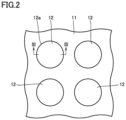
- Fig. 2 is a schematic enlarged view of the surface 11. As illustrated in Fig. 2 , a plurality of recesses 12 are formed on surface 11. Each of the plurality of recesses 12 is disposed apart from each other. In plan view, recess 12 is, for example, circular. Recess 12 may not be circular in plan view.
- the equivalent circle diameter of recess 12 is, for example, less than or equal to 100 ⁇ m.
- the equivalent circle diameter of recess 12 is, for example, greater than or equal to 1 ⁇ m.
- the equivalent circle diameter of recess 12 is preferably greater than or equal to 1 ⁇ m and less than or equal to 71 ⁇ m.
- the equivalent circle diameter of recess 12 is a square root of a value obtained by dividing an area of recess 12 in plan view by ⁇ /4.
- a ratio of a total area of the plurality of recesses 12 to an area of surface 11 (hereinafter referred to as an "area ratio of recesses 12") is, for example, greater than or equal to 1%.
- the area ratio of recesses 12 is preferably greater than or equal to 1% and less than or equal to 80%.
- the area ratio of recesses 12 is, for example, less than or equal to 85%.
- the ratio of the total area of the plurality of recesses 12 to the area of surface 11 is measured by the following method. First, an SEM image of surface 11 is taken. At this time, the size of the measurement visual field is 200 ⁇ m ⁇ 200 ⁇ m, and the magnification is 500 times. The five SEM images are taken at different positions. Secondly, the ratio of the total area of the plurality of recesses 12 to the area of surface 11 is calculated for each of the five SEMs. The average value of the total ratios of the areas of the plurality of recesses 12 to the area of surface 11 obtained from the five SEM images is taken as the area ratio of recesses 12.
- Fig. 3 is a cross-sectional view taken along line III-III in Fig. 2 .
- Recess 12 has an opening edge 12a and a side surface 12b continuous with opening edge 12a. Opening edge 12a constitutes a cutting edge of cutting tool 100. That is, opening edge 12a is a sharp edge.
- a depth of recess 12 is defined as a depth D.
- Depth D is a distance between opening edge 12a and the bottom of recess 12 in a cross-sectional view passing through the center of recess 12 in a plan view and orthogonal to surface 11.
- Recess 12 is measured by an optical measuring device or a non-contact three-dimensional measuring device.
- Depth D is, for example, less than or equal to 25 ⁇ m.
- Depth D is preferably greater than or equal to 1 ⁇ m and less than or equal to 25 ⁇ m.
- Depth D is, for example, greater than or equal to 0.1 ⁇ m.
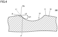
- Fig. 4 is a schematic diagram illustrating a method of measuring angle ⁇ .
- Angle ⁇ is measured by the method illustrated in Fig. 4 .
- the coordinates of measurement points P are measured by an optical measuring device or a non-contact three-dimensional measuring device.
- the plurality of measurement points P are sequentially arranged at equal intervals (0.2 ⁇ m intervals) from opening edge 12a to positions where the distance from opening edge 12a is 1 ⁇ m.
- a curved line representing side surface 12b is determined based on the coordinates of each of the plurality of measurement points P.
- Tangent line L1 is a tangent line at opening edge 12a of the curved line representing side surface 12b.
- Tangent line L2 is a tangent line at opening edge 12a of a curved line indicating a portion of surface 11 continuous with opening edge 12a.
- An angle formed by tangent line L1 and tangent line L2 is angle ⁇ .
- Angle ⁇ is, for example, less than or equal to 170°. Angle ⁇ is preferably greater than or equal to 80° and less than or equal to 160° in recesses greater than or equal to 80% of the plurality of recesses 12. Note that angle ⁇ is measured for arbitrary 10 of the plurality of recesses 12, and if angle ⁇ falls within the range of greater than or equal to 80° and less than or equal to 160° for 8 or more of the recesses, it is considered that "angle ⁇ is greater than or equal to 80° and less than or equal to 160° in the recesses greater than or equal to 80% of the plurality of recesses 12".
- Fig. 5 is a schematic view of tip end portion 10 illustrating the arrangement of recesses 12.
- the plurality of recesses 12 are arranged in a plurality of rows extending from a central portion of surface 11, for example.
- Each of the plurality of columns includes a plurality of recesses 12.
- One of the plurality of columns is defined as a first column.
- Another one of the plurality of columns adjacent to the first column is defined as a second column.
- Recesses 12 belonging to the first row are referred to as recesses 12A.
- Recesses 12 belonging to the second row are referred to as recesses 12B.
- recess 12B is disposed between two adjacent recesses 12A, for example.
- the equivalent circle diameter of recess 12B is larger than, for example, an interval between two adjacent recesses 12A (an interval between two adjacent recesses 12B). Therefore, trajectories of the plurality of recesses 12A and recesses 12B cover all of surface 11 when cutting tool 100 is rotated about rotation axis A.
- Recesses 12 are formed, for example, by irradiating surface 11 with a laser.
- the laser is, for example, a YAG laser.
- the shape of recesses 12 (equivalent circle diameter, angle ⁇ , and depth D) changes depending on laser irradiation conditions.
- the laser irradiation conditions include, for example, an average power (unit: W), a repetition frequency (unit: Hz), and a laser scanning speed (unit: mm/min). Table 1 shows the shape of recesses 12 when the laser irradiation condition is changed.
- Fig. 6 is a perspective view of cutting tool 100 according to a modified example. As illustrated in Fig. 6 , a plurality of flutes 13 may be provided on surface 11. Flutes 13 extend radially from the central portion of surface 11. Although not shown, the plurality of recesses 12 are located between adjacent flutes 13. Edges of flutes 13 function as cutting edges of cutting tool 100 together with opening edges 12a.
- cutting tool 200 effects of cutting tool 100 will be described in comparison with a cutting tool according to a comparative example (hereinafter referred to as a "cutting tool 200").
- Fig. 7 is a schematic cross-sectional view of cutting tool 200.
- Fig. 7 illustrates a cross section of cutting tool 200 passing through the center of recess 12 in plan view and orthogonal to surface 11.
- recess 12 is formed to reduce contact resistance with the workpiece.
- opening edge 12a passes through the center of recess 12 in a plan view and has an R shape in a cross-sectional view orthogonal to surface 11.
- opening edge 12a does not function as a cutting edge.
- opening edge 12a is a sharp edge
- opening edge 12a can function as a cutting edge.
- cutting tool 100 can perform cutting on the workpiece.
- the plurality of recesses 12 are arranged such that the trajectories of the plurality of recesses 12 cover all of surface 11 when cutting tool 100 is rotated about rotation axis A, the all of surface 11 can be subjected to cutting on the workpiece, and the cutting efficiency of cutting tool 100 is improved. In this case, it is possible to improve the processing quality of the workpiece after the cutting (glossiness and surface roughness of the workpiece after the cutting).
- a cutting test was performed.
- a first cutting condition, a second cutting condition, a third cutting condition, a fourth cutting condition, a fifth cutting condition, a sixth cutting condition, a seventh cutting condition, and an eighth cutting condition were applied.
- the first to eighth cutting conditions are shown in Table 2.
- the rotation speed, the feed amount, the cutting width, and the cutting method of cutting tool 100 were respectively 40,000 rotations/min, 300 mm/min, 0.002 mm, and down cutting.
- the rotation speed, the feed amount, the cut width, and the cutting method of cutting tool 100 were respectively set to 40,000 rotations/min, 800 mm/min, 0.005 mm, and down cutting.
- the workpiece was made of cemented carbide.
- the workpiece was made of quartz glass.
- the workpiece was made of hardened steel. Under the first to eighth cutting conditions, a plane of 5 mm ⁇ 5 mm was cut.
- the cut depth was 0.005 mm. Under the second cutting condition to the fourth cutting condition and the seventh cutting condition, the cut depth was 0.003 m. Under the fifth cutting condition and the sixth cutting condition, the cut depth was 0.004 mm. Under the first cutting condition and the third cutting condition to the eighth cutting condition, cutting was performed while mist-like oil was supplied as a coolant. Under the second cutting condition, the cutting was performed by dry machining (that is, no coolant is supplied).
- a dimensional error from a target shape of the workpiece after cutting of each sample (hereinafter, referred to as a "dimensional error"), a glossiness of the workpiece after cutting (hereinafter, referred to as a “glossiness”), and an arithmetic average roughness of the workpiece after cutting (hereinafter, referred to as a "surface roughness”) were evaluated.
- a dimensional error from a target shape of the workpiece after cutting of each sample
- glossiness a glossiness of the workpiece after cutting
- a surface roughness an arithmetic average roughness of the workpiece after cutting
- the glossiness was measured using a gloss meter.
- the specular reflectivity at an incident angle of 60° of a black mirror glass plate having a refractive index of 1.567 was defined as a case where the glossiness was 100 (specular glossiness).
- samples 1 to 30 were provided as samples of cutting tool 100.
- the presence or absence of recess 12, depth D, the equivalent circle diameter of recess 12, the area ratio of recess 12, angle ⁇ , and the material of tip end portion 10 were changed.
- NPD means nano polycrystalline diamond
- B-NPD means nano polycrystalline diamond doped with boron
- BL-CBN means a binderless cubic boron nitride.
- the plurality of recesses 12 were not arranged such that trajectories of the plurality of recesses 12 cover all of surface 11 when rotated about rotation axis A.
- the plurality of recesses 12 were arranged such that trajectories of the plurality of recesses 12 cover all of surface 11 when rotated about rotation axis A.
- the plurality of flutes 13 were provided on surface 11.
- a condition A is that depth D is greater than or equal to 1 ⁇ m.
- a condition B is that the equivalent circle diameter of recess 12 is greater than or equal to 1 ⁇ m.
- a condition C is that the area ratio of recess 12 is greater than or equal to 1%.
- sample 1 and sample 2 As the dimensional error of sample 1 and sample 2 was greater than or equal to 4 ⁇ m, and sample 1 and sample 2 could not be evaluated as functioning as a cutting tool. On the other hand, as the dimensional error of samples 3 to 30 was less than 4 ⁇ m, samples 3 to 30 functioned as a cutting tool. From this comparison, it was experimentally revealed that opening edge 12a functions as a cutting edge when recess 12 satisfies two or more of conditions A to C.
- the equivalent circle diameter of recess 12 was in a range of 50 ⁇ m ⁇ 2 ⁇ m.
- the area ratio of recess 12 was within a range of 20% ⁇ 4%, and the angle ⁇ was within a range of 90° ⁇ 1°.
- depth D was sequentially increased.
- depth D was in a range greater than or equal to 1 ⁇ m and less than or equal to 25 ⁇ m, and high glossiness and low surface roughness were obtained. From this, it has been experimentally found that, by setting depth D to be greater than or equal to 1 ⁇ m and less than or equal to 25 ⁇ m, the processing quality when cutting is performed using cutting tool 100 is improved.
- depth D was in a range of 5 ⁇ m ⁇ 0.2 ⁇ m.
- the area ratio of recess 12 was within a range of 20% ⁇ 2%, and angle ⁇ was within a range of 90° ⁇ 1°.
- the equivalent circle diameter of recess 12 was sequentially increased.
- the equivalent circle diameter of recess 12 was in a range greater than or equal to 1 ⁇ m and less than or equal to 71 ⁇ m, and high glossiness and low surface roughness were obtained. From this, it has been experimentally found that, by setting the equivalent circle diameter of recess 12 to be greater than or equal to 1 ⁇ m and less than or equal to 71 ⁇ m, the processing quality when cutting is performed using cutting tool 100 is improved.
- depth D was in a range of 5 ⁇ m ⁇ 0.4 ⁇ m.
- the equivalent circle diameter of recess 12 was within a range of 48 ⁇ m ⁇ 2 ⁇ m, and angle ⁇ was within a range of 90° ⁇ 2°.
- the area ratio of recess 12 was sequentially increased.
- the area ratio of recess 12 was in a range of greater than or equal to 1% and less than or equal to 80%, and high glossiness and low surface roughness were obtained. From this, it has been experimentally found that by setting the area ratio of recesses 12 to be greater than or equal to 1% and less than or equal to 80%, the processing quality when cutting is performed using cutting tool 100 is improved.
- depth D was in a range of 5 ⁇ m ⁇ 0.5 ⁇ m.
- the equivalent circle diameter of recess 12 was within a range of 50 ⁇ m ⁇ 1 ⁇ m, and the area ratio of recess 12 was within a range of 18% ⁇ 2%.
- angle ⁇ was sequentially increased.
- angle ⁇ was in a range greater than or equal to 80° and less than or equal to 160°, and high glossiness and low surface roughness were obtained. From this, it has been experimentally found that by setting angle ⁇ to be greater than or equal to 80° and less than or equal to 160°, the processing quality when cutting is performed using cutting tool 100 is improved.
- sample 28 high glossiness and low surface roughness were obtained as compared with sample 27. From this, it has been experimentally found that by providing the plurality of recesses 12 such that the trajectories of the plurality of recesses 12 cover all of surface 11 when rotated about rotation axis A, processing quality when cutting processing is performed using cutting tool 100 is improved.
Landscapes
- Engineering & Computer Science (AREA)
- Mechanical Engineering (AREA)
- Milling Processes (AREA)
- Cutting Tools, Boring Holders, And Turrets (AREA)
Abstract
Description
- The present disclosure relates to a cutting tool.
- The present application claims priority based on
PCT/JP2020/024454 PCT/JP2020/024455 PCT/JP2020/024456, which are international applications filed on June 22, 2020 -
WO 2018/116524 A (PTL 1) andJapanese Patent Laying-Open No. 2013-212572 - The cutting tool described in PTL 1 has a flat negative land and a flat flank face, and a cutting edge contiguous with the negative land and the flank face. A plurality of recessed portions are formed in at least one of the negative land and the flank face.
- The cutting tool described in PTL 2 has a cutting edge and a rake face contiguous with the cutting edge, and the rake face has a plurality of recessed portions.
-
- PTL 1:
WO 2018/116524 A - PTL 2:
Japanese Patent Laying-Open No. 2013-212572 - A cutting tool of the present disclosure rotates about a rotation axis and includes a tip end portion. The tip end portion includes a partially spherical surface that is brought into contact with a workpiece. The surface is provided with a plurality of recesses disposed apart from each other. An opening edge of each of the plurality of recesses constitutes a cutting edge.
-
-
Fig. 1 is a perspective view of acutting tool 100. -
Fig. 2 is a schematic enlarged view of asurface 11. -
Fig. 3 is a cross-sectional view taken along line III-III inFig. 2 . -
Fig. 4 is a schematic diagram illustrating a method of measuring an angle θ. -
Fig. 5 is a schematic view of atip end portion 10 illustrating arrangement ofrecesses 12. -
Fig. 6 is a perspective view of thecutting tool 100 according to a modified example. -
Fig. 7 is a schematic cross-sectional view of acutting tool 200. - In the cutting tool described in PTL 1, a workpiece is cut by a cutting edge, and recessed portions on a negative land and a flank face are provided in order to reduce contact resistance with the workpiece. Also in the cutting tool described in PTL 2, a workpiece is cut by a cutting edge, and a recessed portion of a rake face is provided in order to reduce contact resistance with the workpiece.
- The present disclosure provides a cutting tool that performs cutting by an opening edge of a recessed portion provided on a partially spherical surface.
- According to the cutting tool of the present disclosure, cutting can be performed by an opening edge of a recessed portion provided on a partially spherical surface.
- Hereinafter, an embodiment of the present disclosure will be listed and described.
- (1) The cutting tool according to the embodiment rotates about a rotation axis and includes a tip end portion. The tip end portion includes a partially spherical surface that is brought into contact with a workpiece. The surface is provided with a plurality of recesses disposed apart from each other. An opening edge of each of the plurality of recesses constitutes a cutting edge.
According to the cutting tool of (1), cutting can be performed by the opening edges of the recessed portions provided on the partially spherical surface. - (2) In the cutting tool of (1), the tip end portion may be formed of binderless cubic boron nitride or nano polycrystalline diamond.
- (3) In the cutting tool of (2), to the nano polycrystalline diamond, atoms belonging to the
group 13 or 15 of the long form of the periodic table may be added. - (4) In the cutting tool of (1) to (3), each of the plurality of recesses may have a side surface continuous with the opening edge. For recesses greater than or equal to 80% of the plurality of recesses, an angle between the side surface and a portion of the surface continuous with the opening edge may be greater than or equal to 80° and less than or equal to 160°.
- (5) In the cutting tool of the above (1) to (4), the plurality of recesses may be arranged such that trajectories of the plurality of recesses cover all of the surface when the cutting tool is rotated about the rotation axis.
- (6) In the cutting tool of (1) to (5), the surface may be provided with a plurality of flutes extending radially from a central portion of the surface. The plurality of recesses may be disposed at portions of the surface between the plurality of flutes.
- (7) The cutting tool of (1) to (6) may be used with a cut depth of less than or equal to 10 µm.
- Details of the embodiment according to the present disclosure will be described with reference to the drawings. In the following drawings, the same or corresponding parts are denoted by the same reference numerals, and redundant description will not be repeated. The cutting tool according to the embodiment is referred to as a
cutting tool 100. - Hereinafter, the configuration of
cutting tool 100 will be described. -
Fig. 1 is a perspective view ofcutting tool 100. As illustrated inFig. 1 ,cutting tool 100 is, for example, a ball end mill.Cutting tool 100 is rotated about a rotation axis A to perform cutting on a workpiece.Cutting tool 100 is used for cutting a workpiece with a cut depth of less than or equal to 10 µm, for example.Cutting tool 100 includes atip end portion 10, amain body 20, and aconnection layer 30. -
Tip end portion 10 is located at the tip ofcutting tool 100 in the direction along the rotation axis A.Tip end portion 10 has asurface 11.Surface 11 is partially spherical.Surface 11 has a hemispherical shape, for example.Surface 11 is brought into contact with the workpiece.Tip end portion 10 is formed of binderless cubic boron nitride (cBN), for example. - The binderless cubic boron nitride includes a plurality of cubic boron nitride grains. The rest of the binderless cubic boron nitride may contain boron nitride having a crystal structure other than a cubic crystal such as hexagonal boron nitride (hBN) or wurtzite boron nitride (wBN), as well as inevitable impurities, but does not contain a binder. That is, in the binderless cubic boron nitride, the cubic boron nitride grains are directly bonded to each other without a binder. The amount of the inevitable impurities is preferably as small as possible, but may be several percent with respect to the total mass.
- In the binderless cubic boron nitride, a median size of the cubic boron nitride crystal grains is less than 1 µm, for example. In the binderless cubic boron nitride, the median size of the cubic boron nitride crystal grains is preferably less than or equal to 0.05 µm. In the binderless cubic boron nitride, the median size of the cubic boron nitride crystal grains is greater than or equal to 0.01 µm, for example.
- The median size of the cubic boron nitride crystal grains is measured, for example, by the following method. First, a scanning electron microscope (SEM) image in a cross section of
tip end portion 10 is taken. The size of the measurement visual field is 12 µm × 15 µm, and the observation magnification is 10,000 times. The five SEM images are taken at different positions. - Secondly, distributions of equivalent circle diameters of the cubic boron nitride crystal grains are calculated by performing image analysis on each of the five SEM images using image processing software (Win Roof Ver. 7.4.5). The median size of the cubic boron nitride crystal grains is calculated based on the distribution of the equivalent circle diameters. The average value of the median sizes obtained from the five SEM images is defined as the median size of the cubic boron nitride crystal grains.
-
Tip end portion 10 may be formed of nano polycrystalline diamond. The nano polycrystalline diamond contains a plurality of diamond crystal grains. The rest of the nano polycrystalline diamond may contain inevitable impurities, but does not contain a binder. That is, in the nano polycrystalline diamond, the plurality of diamond crystal grains are directly bonded to each other. The inevitable impurities are hydrogen and oxygen, for example. - In the nano polycrystalline diamond, the median size of diamond crystal grains is less than 1 µm, for example. Preferably, in the nano polycrystalline diamond, the median size of diamond crystal grains is less than or equal to 0.5 µm, for example. In the nano polycrystalline diamond, the median size of diamond crystal grains is greater than or equal to 0.01 µm, for example. The median size of the diamond crystal grains is measured by the same method as the median size of the cubic boron nitride crystal grains.
- Atoms belonging to
group 13 or 15 of the long form of the periodic table may be added to the nano polycrystalline diamond. The atoms belonging to Group 13 of the long form of the periodic table are boron (B), aluminum (Al), and gallium (Ga), for example. The atoms belonging to Group 15 of the long form of the periodic table are nitrogen (N), phosphorus (P), and arsenic (As), for example. - In the nano polycrystalline diamond to which the atoms are added, a part of carbon atoms in the diamond crystal structure may be substituted with the atoms described above, or the atoms described above may be inserted between carbon and carbon. The concentration of the atoms to be added is, for example, greater than or equal to 1 ppm and less than or equal to 10,000 ppm. The concentration of the atoms added to the nano polycrystalline diamond can be measured by secondary ion mass spectrometry (SIMS) analysis, for example.
-
Main body 20 is, for example, a shank.Main body 20 is made of, for example, cemented carbide.Main body 20 extends along the rotation axisA. Main body 20 has, for example, a circular shape in a cross-sectional view orthogonal to rotation axis A.Tip end portion 10 is attached to a tip end ofmain body 20 in the direction along rotation axis A.Tip end portion 10 is attached tomain body 20 viaconnection layer 30.Tip end portion 10 is attached tomain body 20 by, for example, brazing. That is,connection layer 30 is, for example, a brazing material. -
Fig. 2 is a schematic enlarged view of thesurface 11. As illustrated inFig. 2 , a plurality ofrecesses 12 are formed onsurface 11. Each of the plurality ofrecesses 12 is disposed apart from each other. In plan view,recess 12 is, for example, circular.Recess 12 may not be circular in plan view. - The equivalent circle diameter of
recess 12 is, for example, less than or equal to 100 µm. The equivalent circle diameter ofrecess 12 is, for example, greater than or equal to 1 µm. The equivalent circle diameter ofrecess 12 is preferably greater than or equal to 1 µm and less than or equal to 71 µm. The equivalent circle diameter ofrecess 12 is a square root of a value obtained by dividing an area ofrecess 12 in plan view by π/4. - A ratio of a total area of the plurality of
recesses 12 to an area of surface 11 (hereinafter referred to as an "area ratio ofrecesses 12") is, for example, greater than or equal to 1%. The area ratio ofrecesses 12 is preferably greater than or equal to 1% and less than or equal to 80%. The area ratio ofrecesses 12 is, for example, less than or equal to 85%. - The ratio of the total area of the plurality of
recesses 12 to the area ofsurface 11 is measured by the following method. First, an SEM image ofsurface 11 is taken. At this time, the size of the measurement visual field is 200 µm × 200 µm, and the magnification is 500 times. The five SEM images are taken at different positions. Secondly, the ratio of the total area of the plurality ofrecesses 12 to the area ofsurface 11 is calculated for each of the five SEMs. The average value of the total ratios of the areas of the plurality ofrecesses 12 to the area ofsurface 11 obtained from the five SEM images is taken as the area ratio ofrecesses 12. -
Fig. 3 is a cross-sectional view taken along line III-III inFig. 2 .Recess 12 has anopening edge 12a and aside surface 12b continuous with openingedge 12a. Openingedge 12a constitutes a cutting edge of cuttingtool 100. That is, openingedge 12a is a sharp edge. A depth ofrecess 12 is defined as a depth D. Depth D is a distance between openingedge 12a and the bottom ofrecess 12 in a cross-sectional view passing through the center ofrecess 12 in a plan view and orthogonal to surface 11.Recess 12 is measured by an optical measuring device or a non-contact three-dimensional measuring device. Depth D is, for example, less than or equal to 25 µm. Depth D is preferably greater than or equal to 1 µm and less than or equal to 25 µm. Depth D is, for example, greater than or equal to 0.1 µm. -
Surface 11 continuous with openingedge 12a andside surface 12b makes an angle θ.Fig. 4 is a schematic diagram illustrating a method of measuring angle θ. Angle θ is measured by the method illustrated inFig. 4 . First, in a cross-sectional view passing through the center ofrecess 12 in a plan view, coordinates of a plurality of measurement points P onside surface 12b are measured. The coordinates of measurement points P are measured by an optical measuring device or a non-contact three-dimensional measuring device. The plurality of measurement points P are sequentially arranged at equal intervals (0.2 µm intervals) from openingedge 12a to positions where the distance from openingedge 12a is 1 µm. Secondly, a curved line representingside surface 12b is determined based on the coordinates of each of the plurality of measurement points P. - Thirdly, an angle formed by a tangent line L1 and a tangent line L2 is calculated. Tangent line L1 is a tangent line at opening
edge 12a of the curved line representingside surface 12b. Tangent line L2 is a tangent line at openingedge 12a of a curved line indicating a portion ofsurface 11 continuous with openingedge 12a. An angle formed by tangent line L1 and tangent line L2 is angle θ. - Angle θ is, for example, less than or equal to 170°. Angle θ is preferably greater than or equal to 80° and less than or equal to 160° in recesses greater than or equal to 80% of the plurality of
recesses 12. Note that angle θ is measured for arbitrary 10 of the plurality ofrecesses 12, and if angle θ falls within the range of greater than or equal to 80° and less than or equal to 160° for 8 or more of the recesses, it is considered that "angle θ is greater than or equal to 80° and less than or equal to 160° in the recesses greater than or equal to 80% of the plurality ofrecesses 12". -
Fig. 5 is a schematic view oftip end portion 10 illustrating the arrangement ofrecesses 12. As illustrated inFig. 5 , the plurality ofrecesses 12 are arranged in a plurality of rows extending from a central portion ofsurface 11, for example. InFig. 5 , only two columns adjacent to each other among the plurality of columns are illustrated. Each of the plurality of columns includes a plurality ofrecesses 12. One of the plurality of columns is defined as a first column. Another one of the plurality of columns adjacent to the first column is defined as a second column.Recesses 12 belonging to the first row are referred to asrecesses 12A.Recesses 12 belonging to the second row are referred to as recesses 12B. - In the direction along rotation axis A, recess 12B is disposed between two
adjacent recesses 12A, for example. The equivalent circle diameter of recess 12B (recess 12A) is larger than, for example, an interval between twoadjacent recesses 12A (an interval between two adjacent recesses 12B). Therefore, trajectories of the plurality ofrecesses 12A and recesses 12B cover all ofsurface 11 when cuttingtool 100 is rotated about rotation axis A. -
Recesses 12 are formed, for example, by irradiatingsurface 11 with a laser. The laser is, for example, a YAG laser. The shape of recesses 12 (equivalent circle diameter, angle θ, and depth D) changes depending on laser irradiation conditions. The laser irradiation conditions include, for example, an average power (unit: W), a repetition frequency (unit: Hz), and a laser scanning speed (unit: mm/min). Table 1 shows the shape ofrecesses 12 when the laser irradiation condition is changed. -
Table 1 Average power (W) Repetition frequency (Hz) Laser scanning speed (mm/min) Angle θ (°) Depth D (mm) 1 50 100 138 0.004 3 50 100 115 0.009 5 50 100 91 0.019 -
Fig. 6 is a perspective view of cuttingtool 100 according to a modified example. As illustrated inFig. 6 , a plurality offlutes 13 may be provided onsurface 11.Flutes 13 extend radially from the central portion ofsurface 11. Although not shown, the plurality ofrecesses 12 are located betweenadjacent flutes 13. Edges offlutes 13 function as cutting edges of cuttingtool 100 together with openingedges 12a. - Hereinafter, effects of cutting
tool 100 will be described in comparison with a cutting tool according to a comparative example (hereinafter referred to as a "cuttingtool 200"). -
Fig. 7 is a schematic cross-sectional view of cuttingtool 200.Fig. 7 illustrates a cross section of cuttingtool 200 passing through the center ofrecess 12 in plan view and orthogonal to surface 11. In cuttingtool 200,recess 12 is formed to reduce contact resistance with the workpiece. As illustrated inFig. 7 , in cuttingtool 200, in order to prevent a breakage of openingedge 12a, openingedge 12a passes through the center ofrecess 12 in a plan view and has an R shape in a cross-sectional view orthogonal to surface 11. As a result, in cuttingtool 200, openingedge 12a does not function as a cutting edge. - On the other hand, in cutting
tool 100, since openingedge 12a is a sharp edge, openingedge 12a can function as a cutting edge. As described above, by rotatingcutting tool 100 about rotation axis A whilesurface 11 is in contact with the workpiece, cuttingtool 100 can perform cutting on the workpiece. - In a case where the plurality of
recesses 12 are arranged such that the trajectories of the plurality ofrecesses 12 cover all ofsurface 11 when cuttingtool 100 is rotated about rotation axis A, the all ofsurface 11 can be subjected to cutting on the workpiece, and the cutting efficiency of cuttingtool 100 is improved. In this case, it is possible to improve the processing quality of the workpiece after the cutting (glossiness and surface roughness of the workpiece after the cutting). - When the plurality of
flutes 13 are provided onsurface 11, not only openingedge 12a but also the edges offlutes 13 functions as a cutting edge, and the cutting efficiency of cuttingtool 100 is improved. - In order to confirm the effect of cutting
tool 100, a cutting test was performed. For the cutting test, a first cutting condition, a second cutting condition, a third cutting condition, a fourth cutting condition, a fifth cutting condition, a sixth cutting condition, a seventh cutting condition, and an eighth cutting condition were applied. The first to eighth cutting conditions are shown in Table 2. -
Table 2 Rotation speed Feed amount Cut depth Cut width Coolant Cutting method Workpiece Workpiece hardness (HRA) First cutting condition 40,000 rotations/min 300 mm/min 0.005mm 0.002mm Oil mist Down cutting Cemented carbide 91 Second cutting condition 40,000 rotations/min 300 mm/min 0.003mm 0.002mm Dry processing Down cutting Quartz glass - Third cutting condition 40,000 rotations/min 300 mm/min 0.003mm 0.002mm Oil mist Down cutting Cemented carbide 91 Fourth cutting condition 40,000 rotations/min 300 mm/min 0.003mm 0.002mm Oil mist Down cutting Cemented carbide 71 Fifth cutting condition 40,000 rotations/min 300 mm/min 0.004mm 0.002mm Oil mist Down cutting Cemented carbide 71 Sixth cutting condition 40,000 rotations/min 300 mm/min 0.004mm 0.002mm Oil mist Down cutting Cemented carbide 91 Seventh cutting condition 40,000 rotations/min 300 mm/min 0.003mm 0.002mm Oil mist Down cutting Cemented carbide 67 Eighth cutting condition 40,000 rotations/min 800 mm/min 0.005mm 0.005mm Oil mist Down cutting Hardened steel 77.4 - Under the first cutting condition to the seventh cutting condition, the rotation speed, the feed amount, the cutting width, and the cutting method of cutting
tool 100 were respectively 40,000 rotations/min, 300 mm/min, 0.002 mm, and down cutting. In the eighth cutting condition, the rotation speed, the feed amount, the cut width, and the cutting method of cuttingtool 100 were respectively set to 40,000 rotations/min, 800 mm/min, 0.005 mm, and down cutting. Under the first cutting condition and the third cutting condition to the seventh cutting condition, the workpiece was made of cemented carbide. In the second cutting condition, the workpiece was made of quartz glass. In the eighth cutting condition, the workpiece was made of hardened steel. Under the first to eighth cutting conditions, a plane of 5 mm × 5 mm was cut. - Under the first cutting condition and the eighth cutting condition, the cut depth was 0.005 mm. Under the second cutting condition to the fourth cutting condition and the seventh cutting condition, the cut depth was 0.003 m. Under the fifth cutting condition and the sixth cutting condition, the cut depth was 0.004 mm. Under the first cutting condition and the third cutting condition to the eighth cutting condition, cutting was performed while mist-like oil was supplied as a coolant. Under the second cutting condition, the cutting was performed by dry machining (that is, no coolant is supplied).
- In the cutting test, a dimensional error from a target shape of the workpiece after cutting of each sample (hereinafter, referred to as a "dimensional error"), a glossiness of the workpiece after cutting (hereinafter, referred to as a "glossiness"), and an arithmetic average roughness of the workpiece after cutting (hereinafter, referred to as a "surface roughness") were evaluated. When the absolute value of the dimensional error was less than 4 µm, each sample was evaluated as functioning as a cutting tool. When the absolute value of the dimensional error was greater than or equal to 4 µm, it was evaluated that each sample did not function as a cutting tool.
- The glossiness was measured using a gloss meter. The specular reflectivity at an incident angle of 60° of a black mirror glass plate having a refractive index of 1.567 was defined as a case where the glossiness was 100 (specular glossiness).
- In the cutting test, samples 1 to 30 were provided as samples of cutting
tool 100. In each of samples 1 to 30, the presence or absence ofrecess 12, depth D, the equivalent circle diameter ofrecess 12, the area ratio ofrecess 12, angle θ, and the material oftip end portion 10 were changed. In Table 3, "NPD" means nano polycrystalline diamond, "B-NPD" means nano polycrystalline diamond doped with boron, and "BL-CBN" means a binderless cubic boron nitride. - In sample 27, the plurality of
recesses 12 were not arranged such that trajectories of the plurality ofrecesses 12 cover all ofsurface 11 when rotated about rotation axis A. In sample 28, the plurality ofrecesses 12 were arranged such that trajectories of the plurality ofrecesses 12 cover all ofsurface 11 when rotated about rotation axis A. In sample 29, the plurality offlutes 13 were provided onsurface 11. - A condition A is that depth D is greater than or equal to 1 µm. A condition B is that the equivalent circle diameter of
recess 12 is greater than or equal to 1 µm. A condition C is that the area ratio ofrecess 12 is greater than or equal to 1%.[Table 3] Table 3 (1/2) Cutting conditions Depth D Equivalent circle diameter Area ratio Angle θ Material of tip end portion 10 Glossiness Surface roughness Dimensional error (mm) (mm) (%) (°) (nm) (mm) Sample 1 First cutting condition - - - - NPD 350 8 -4 Sample 2 First cutting condition 0.1 0.5 1 169.8 NPD 353 8.1 -4 Sample 3 First cutting condition 3 1 10 90.4 NPD 452 5.8 -0.05 Sample 4 Second cutting condition 2.9 1 18 91 NPD Glossy 8 ±0.05 Sample 5 Second cutting condition 3 1.2 19 89 B-NPD Glossy 6 ±0.05 Sample 6 Third cutting condition 0.1 48 21 89 NPD 349 7 -2.5 Sample 7 Third cutting condition 0.3 49.9 20.1 90 NPD 359 7.1 -2 Sample 8 Third cutting condition 1 51 20 90 NPD 441 6.2 -1 Sample 9 Third cutting condition 5 51.1 19 91 NPD 460 4 ±0.05 Sample 10 Third cutting condition 22 50 16 89 NPD 453 6 ±0.05 Sample 11 Fourth cutting condition 4.8 0.5 19 91 NPD 451 6.3 -1 Sample 12 Fourth cutting condition 4.9 10 19 90 NPD 458 6.2 ±0.05 Sample 13 Fourth cutting condition 4.8 46 22 89 NPD 460 5 ±0.05 Sample 14 Fourth cutting condition 4.9 71 21 91 NPD 429 6 ±0.05 Sample 15 Fourth cutting condition 5.1 98 18 91 NPD 350 7.8 ±0.05 Table 3 (2/2) Cutting conditions Depth D Equivalent circle diameter Area ratio Angle θ Material of tip end portion 10 Glossiness Surface roughness Dimensional error (mm) (mm) (%) (°) (nm) (mm) Sample 16 Fifth cutting condition 4.6 46 1 89 NPD 438 6.1 -2 Sample 17 Fifth cutting condition 5.2 48 3 90 NPD 441 6 -2 Sample 18 Fifth cutting condition 5 50 10 90 NPD 453 5 -1 Sample 19 Fifth cutting condition 4.9 44 21 90 NPD 460 4.3 ±0.05 Sample 20 Fifth cutting condition 5 48 38 91 NPD 452 5.1 ±0.05 Sample 21 Fifth cutting condition 5.1 49 80 89 NPD 428 6.8 ±0.05 Sample 22 Fifth cutting condition 4.7 49 85 88 NPD 410 7 ±0.05 Sample 23 Sixth cutting condition 4.5 49 19 91 NPD 453 4.3 ±0.05 Sample 24 Sixth cutting condition 4.9 50 17 112 NPD 451 5.2 ±0.05 Sample 25 Sixth cutting condition 5.2 51 18 159 NPD 438 6 ±0.05 Sample 26 Sixth cutting condition 4.8 51 20 170 NPD 420 8.2 ±0.05 Sample 27 Seventh cutting condition 4.6 45 17 92 NPD 362 8.2 -2.1 Sample 28 Seventh cutting condition 5.3 51 23 90 NPD 438 5.1 ±0.05 Sample 29 Seventh cutting condition 4.9 50 21 89 NPD 390 8.1 ±0.05 Sample 30 Eighth cutting condition 3 1 20 90 BL-CBN 519 15 ±0.05 - As shown in Table 3, no
recess 12 was provided in sample 1. In sample 2,recess 12 was provided. However, in sample 2, condition C was satisfied, but condition A and condition B were not satisfied. On the other hand, in samples 3 to 30, two or more of conditions A to C were satisfied. - As the dimensional error of sample 1 and sample 2 was greater than or equal to 4 µm, and sample 1 and sample 2 could not be evaluated as functioning as a cutting tool. On the other hand, as the dimensional error of samples 3 to 30 was less than 4 µm, samples 3 to 30 functioned as a cutting tool. From this comparison, it was experimentally revealed that opening
edge 12a functions as a cutting edge whenrecess 12 satisfies two or more of conditions A to C. - In samples 4 and 5, depth D, the equivalent circle diameter of
recess 12, and the area ratio ofrecess 12 were about the same. In sample 4,tip end portion 10 was formed of nano polycrystalline diamond, whereas in sample 5, the tip end portion was formed of nano polycrystalline diamond doped with boron. In sample 5, a lower surface roughness was obtained as compared with sample 4. From this comparison, it has been experimentally found that the processing quality when cutting processing is performed on glass is improved by providingtip end portion 10 made of nano polycrystalline diamond doped with boron. - In samples 6 to 10, the equivalent circle diameter of
recess 12 was in a range of 50 µm ± 2 µm. In samples 6 to 10, the area ratio ofrecess 12 was within a range of 20% ± 4%, and the angle θ was within a range of 90° ± 1°. In samples 6 to 10, depth D was sequentially increased. - In samples 8 to 10, depth D was in a range greater than or equal to 1 µm and less than or equal to 25 µm, and high glossiness and low surface roughness were obtained. From this, it has been experimentally found that, by setting depth D to be greater than or equal to 1 µm and less than or equal to 25 µm, the processing quality when cutting is performed using
cutting tool 100 is improved. - In
samples 11 to 15, depth D was in a range of 5 µm ± 0.2 µm. Insamples 11 to 15, the area ratio ofrecess 12 was within a range of 20% ± 2%, and angle θ was within a range of 90° ± 1°. Insamples 11 to 15, the equivalent circle diameter ofrecess 12 was sequentially increased. - In
samples 12 to 14, the equivalent circle diameter ofrecess 12 was in a range greater than or equal to 1 µm and less than or equal to 71 µm, and high glossiness and low surface roughness were obtained. From this, it has been experimentally found that, by setting the equivalent circle diameter ofrecess 12 to be greater than or equal to 1 µm and less than or equal to 71 µm, the processing quality when cutting is performed usingcutting tool 100 is improved. - In samples 16 to 22, depth D was in a range of 5 µm ± 0.4 µm. In samples 16 to 22, the equivalent circle diameter of
recess 12 was within a range of 48 µm ± 2 µm, and angle θ was within a range of 90° ± 2°. In samples 16 to 22, the area ratio ofrecess 12 was sequentially increased. - In samples 16 to 21, the area ratio of
recess 12 was in a range of greater than or equal to 1% and less than or equal to 80%, and high glossiness and low surface roughness were obtained. From this, it has been experimentally found that by setting the area ratio ofrecesses 12 to be greater than or equal to 1% and less than or equal to 80%, the processing quality when cutting is performed usingcutting tool 100 is improved. - In samples 23 to 26, depth D was in a range of 5 µm ± 0.5 µm. In samples 23 to 26, the equivalent circle diameter of
recess 12 was within a range of 50 µm ± 1 µm, and the area ratio ofrecess 12 was within a range of 18% ± 2%. In samples 23 to 26, angle θ was sequentially increased. In samples 23 to 25, angle θ was in a range greater than or equal to 80° and less than or equal to 160°, and high glossiness and low surface roughness were obtained. From this, it has been experimentally found that by setting angle θ to be greater than or equal to 80° and less than or equal to 160°, the processing quality when cutting is performed usingcutting tool 100 is improved. - In sample 28, high glossiness and low surface roughness were obtained as compared with sample 27. From this, it has been experimentally found that by providing the plurality of
recesses 12 such that the trajectories of the plurality ofrecesses 12 cover all ofsurface 11 when rotated about rotation axis A, processing quality when cutting processing is performed usingcutting tool 100 is improved. - In
sample 30, high glossiness and surface roughness were obtained. From this, it has been experimentally found that by providingtip end portion 10 made of binderless cubic boron nitride, the processing quality when cutting processing is performed to hardened steel usingcutting tool 100 is improved. - The embodiment disclosed herein should be considered to be illustrative in all respects and not restrictive. The scope of the present invention is defined by the claims, instead of the embodiment stated above, and it is intended that meanings equivalent to the claims and all modifications within the scope are included.
- 10: tip end portion, 11: surface, 12: recess, 12a: opening edge, 12b: side surface, 13: flute, 20: main body, 30: connection layer, 100: cutting tool, 200: cutting tool, θ: angle, A: rotation axis, D: depth, L1, L2: tangent line, P: measurement point.
Claims (7)
- A cutting tool that rotates about a rotation axis, the cutting tool comprising:a tip end portion, whereinthe tip end portion includes a partially spherical surface that is brought into contact with a workpiece,the surface is provided with a plurality of recesses disposed apart from each other, andan opening edge of each of the plurality of recesses constitutes a cutting edge.
- The cutting tool according to claim 1, wherein the tip end portion is formed of binderless cubic boron nitride or nano polycrystalline diamond.
- The cutting tool according to claim 2, wherein to the nano polycrystalline diamond, atoms belonging to the group 13 or 15 of the long form of the periodic table are added.
- The cutting tool according to any one of claims 1 to 3, whereineach of the plurality of recesses has a side surface continuous with the opening edge, andfor recesses greater than or equal to 80% of the plurality of recesses, an angle between the side surface and a portion of the surface continuous with the opening edge is greater than or equal to 80° and less than or equal to 160°.
- The cutting tool according to any one of claims 1 to 4, wherein the plurality of recesses are arranged such that trajectories of the plurality of recesses cover all of the surface when the cutting tool is rotated about the rotation axis.
- The cutting tool according to any one of claims 1 to 5, whereinthe surface is provided with a plurality of flutes extending radially from a central portion of the surface, andthe plurality of recesses are disposed at portions of the surface between the plurality of flutes.
- The cutting tool according to any one of claims 1 to 6, wherein the cutting tool is used with a cut depth of less than or equal to 10 µm.
Applications Claiming Priority (4)
| Application Number | Priority Date | Filing Date | Title |
|---|---|---|---|
| JP2020024456 | 2020-06-22 | ||
| JP2020024455 | 2020-06-22 | ||
| JP2020024454 | 2020-06-22 | ||
| PCT/JP2021/023085 WO2021261380A1 (en) | 2020-06-22 | 2021-06-17 | Cutting tool |
Publications (2)
| Publication Number | Publication Date |
|---|---|
| EP4169645A1 true EP4169645A1 (en) | 2023-04-26 |
| EP4169645A4 EP4169645A4 (en) | 2023-12-13 |
Family
ID=79281360
Family Applications (1)
| Application Number | Title | Priority Date | Filing Date |
|---|---|---|---|
| EP21829827.1A Pending EP4169645A4 (en) | 2020-06-22 | 2021-06-17 | CUTTING TOOL |
Country Status (6)
| Country | Link |
|---|---|
| US (1) | US12186815B2 (en) |
| EP (1) | EP4169645A4 (en) |
| JP (1) | JP7133118B2 (en) |
| CN (1) | CN115702053B (en) |
| TW (1) | TWI893142B (en) |
| WO (1) | WO2021261380A1 (en) |
Family Cites Families (63)
| Publication number | Priority date | Publication date | Assignee | Title |
|---|---|---|---|---|
| US960526A (en) * | 1907-12-21 | 1910-06-07 | Julius Erlandsen | Rotary cutter. |
| US3548476A (en) * | 1969-04-25 | 1970-12-22 | Dixie Tool Ind Inc | Milling cutter construction |
| BE759406R (en) * | 1970-04-24 | 1971-04-30 | Weldon Tool Co | CUTTING TOOL |
| US4285618A (en) * | 1979-10-12 | 1981-08-25 | Shanley Stephen E Jr | Rotary milling cutter |
| DE8021563U1 (en) | 1980-08-12 | 1984-03-15 | Walter Kieninger KG, 7630 Lahr | MILLING TOOL FOR MILLING GROOVES, IN PARTICULAR BALL PATHS OF HOMOKINETIC JOINTS |
| JPS5990566U (en) | 1982-12-07 | 1984-06-19 | ジ−エヌツ−ル株式会社 | Spherical cutter |
| US4593777A (en) * | 1983-02-22 | 1986-06-10 | Nl Industries, Inc. | Drag bit and cutters |
| US4770567A (en) * | 1983-06-20 | 1988-09-13 | Colt Industries Operating Corp. | Roughing cutter |
| US4796709A (en) * | 1986-01-06 | 1989-01-10 | Tri-State Oil Tool Industries, Inc. | Milling tool for cutting well casing |
| JPH0674524B2 (en) * | 1986-07-30 | 1994-09-21 | 小林テキスタイルエンジニヤリング株式会社 | Flying fineness prevention device of automatic reeling machine |
| JPH0325862Y2 (en) | 1987-04-28 | 1991-06-05 | ||
| JPH0445616U (en) | 1990-08-22 | 1992-04-17 | ||
| JP3416197B2 (en) * | 1993-05-27 | 2003-06-16 | 日進工具株式会社 | End mill |
| US5984005A (en) * | 1995-09-22 | 1999-11-16 | Weatherford/Lamb, Inc. | Wellbore milling inserts and mills |
| JP4035184B2 (en) * | 1996-10-11 | 2008-01-16 | 日立ツール株式会社 | Polygonal end mill |
| US6951563B2 (en) * | 2002-03-22 | 2005-10-04 | Symmetry Medical, Inc. | Orthopaedic reamer with flat cutting teeth |
| US7232311B1 (en) * | 2002-04-19 | 2007-06-19 | Greggs Thomas S | Bur for preparing metal substrates |
| US20050133277A1 (en) * | 2003-08-28 | 2005-06-23 | Diamicron, Inc. | Superhard mill cutters and related methods |
| JP2006255814A (en) * | 2005-03-16 | 2006-09-28 | Micro Diamond Corp | Micro rotating tool |
| JP4746339B2 (en) | 2005-03-31 | 2011-08-10 | 一般財団法人機械振興協会 | Cutting tool manufacturing method |
| JP2006315088A (en) | 2005-05-10 | 2006-11-24 | Okamoto Machine Tool Works Ltd | Pcd pellet grinding wheel and method of grinding work made of cemented carbide using it |
| US7399147B1 (en) * | 2005-08-09 | 2008-07-15 | Vandyke Jr Daryl C | End mill bit with notched teeth |
| JP2008056542A (en) * | 2006-09-01 | 2008-03-13 | Hitachi Tool Engineering Ltd | Rotary cutting tool for processing glass |
| JP2008122370A (en) | 2006-10-18 | 2008-05-29 | Fukuoka Prefecture | Shape-measuring device and shape-measuring method |
| JP5336095B2 (en) | 2007-02-21 | 2013-11-06 | サイバーレーザー株式会社 | Laser diamond cutting tool and manufacturing method thereof |
| DE102009002738A1 (en) * | 2009-03-07 | 2010-09-23 | Gühring Ohg | End mills |
| US8827600B2 (en) * | 2009-05-25 | 2014-09-09 | Hitachi Tool Engineering, Ltd. | Carbide end mill and cutting method using the end mill |
| IL200742A (en) * | 2009-09-03 | 2016-11-30 | Kennametal Inc | Rotary cutting tool having a cutting edge formed of veined pcd |
| JP5426319B2 (en) * | 2009-10-26 | 2014-02-26 | 住友電気工業株式会社 | Diamond cutting tool and manufacturing method thereof |
| JP3161423U (en) | 2010-05-19 | 2010-07-29 | 有限会社三井刻印 | Grinding tool |
| EP2680992A1 (en) * | 2011-02-28 | 2014-01-08 | CeramTec GmbH | Milling cutter for hard machining |
| JP5891639B2 (en) * | 2011-07-28 | 2016-03-23 | 住友電気工業株式会社 | Polycrystalline diamond and manufacturing method thereof, scribe tool, scribe wheel, dresser, rotary tool, water jet orifice, wire drawing die, and cutting tool |
| EP2738140B1 (en) | 2011-07-28 | 2020-12-23 | Sumitomo Electric Industries, Ltd. | Polycrystalline diamond, manufacturing method therefor, scribe tool, scribe wheel, dresser, rotary tool, water-jet orifice, wire drawing die, cutting tool, and electron source |
| CN102328126B (en) * | 2011-09-22 | 2013-01-23 | 山东理工大学 | Small helix-edge ball-end milling cutter |
| US9144845B1 (en) * | 2012-03-01 | 2015-09-29 | The Boeing Company | Cutting tools with textured surfaces |
| JP5780248B2 (en) | 2012-03-07 | 2015-09-16 | 株式会社豊田中央研究所 | Cutting tool, method for manufacturing the same, and method for manufacturing a cut product |
| JP5468100B2 (en) | 2012-03-26 | 2014-04-09 | オグラ宝石精機工業株式会社 | stylus |
| WO2013145286A1 (en) * | 2012-03-30 | 2013-10-03 | 株式会社牧野フライス製作所 | Workpiece machining method, machine tool, tool path-generating device and tool path-generating program |
| JP5878086B2 (en) * | 2012-06-21 | 2016-03-08 | 住友電工ハードメタル株式会社 | Cutting tool manufacturing method |
| JP5567622B2 (en) | 2012-06-28 | 2014-08-06 | オグラ宝石精機工業株式会社 | stylus |
| JP2014083642A (en) * | 2012-10-24 | 2014-05-12 | Yasuda Kogyo Kk | Ball end mill |
| US20180036810A1 (en) * | 2012-11-16 | 2018-02-08 | Stojan Stojanovski | Rotary cutting tool |
| EP2776194B1 (en) * | 2013-01-09 | 2015-10-28 | August Rüggeberg GmbH & Co. KG | Shank milling tool |
| JP6098440B2 (en) * | 2013-08-29 | 2017-03-22 | 三菱マテリアル株式会社 | Ball end mill |
| US10010332B2 (en) * | 2014-01-29 | 2018-07-03 | Pratt & Whitney Canada Corp. | Cutting tool and corresponding assembly |
| WO2016068064A1 (en) * | 2014-10-28 | 2016-05-06 | 三菱日立ツール株式会社 | Multi flute ball end mill |
| CN204248056U (en) * | 2014-11-23 | 2015-04-08 | 上海工程技术大学 | A kind of ball end mill |
| CN104526040A (en) * | 2014-12-15 | 2015-04-22 | 安徽汇联机械工业有限公司 | Wheel hub cutter |
| CN104741673A (en) * | 2015-03-16 | 2015-07-01 | 哈尔滨理工大学 | Self-lubricating ball end mill and processing method thereof |
| JP5969106B1 (en) * | 2015-12-28 | 2016-08-10 | 日進工具株式会社 | End mill and manufacturing method thereof |
| KR102217842B1 (en) * | 2016-03-31 | 2021-02-19 | 가부시끼가이샤 후지세이사쿠쇼 | The structure of the blade part of the machine tool and its surface treatment method |
| JP7067828B2 (en) | 2016-06-29 | 2022-05-16 | 住友電工ハードメタル株式会社 | Cutting tools |
| WO2018005406A1 (en) | 2016-06-29 | 2018-01-04 | Smith International, Inc. | Binderless cbn sintering with cubic press |
| CN106424883B (en) * | 2016-11-09 | 2019-03-22 | 哈尔滨理工大学 | Multi-functional micro- rose cutter for knitting structure is had in a kind of titanic alloy machining |
| EP3542952A4 (en) * | 2016-11-16 | 2020-07-29 | Sumitomo Electric Hardmetal Corp. | METHOD FOR MACHINING MATERIAL TO BE MACHINED, MACHINE TOOL AND METHOD FOR PRODUCING AN ELEMENT USING A DIAMOND TOOL WITH NANOPOLYCRYSTALLINE DIAMOND OR DIAMETER DIAMONDED IN THE STEAM PHASE |
| JP6788032B2 (en) * | 2016-12-15 | 2020-11-18 | 京セラ株式会社 | Rotating tool |
| KR20180088637A (en) * | 2016-12-20 | 2018-08-06 | 스미또모 덴꼬오 하드메탈 가부시끼가이샤 | Cutting tool and manufacturing method thereof |
| EP3646976B1 (en) | 2017-06-30 | 2024-04-10 | Union Tool Co. | Ball end mill |
| CN207900316U (en) * | 2017-10-24 | 2018-09-25 | 国宏工具系统(无锡)股份有限公司 | A kind of hard alloy processing rose cutter |
| WO2019180873A1 (en) * | 2018-03-22 | 2019-09-26 | 住友電工ハードメタル株式会社 | End mill |
| WO2020139945A1 (en) * | 2018-12-28 | 2020-07-02 | Kyocera Sgs Precision Tools, Inc. | Gapless chipbreaker |
| CN112399898A (en) | 2019-06-13 | 2021-02-23 | 住友电工硬质合金株式会社 | Cutting tool |
| EP3885066B1 (en) | 2019-10-16 | 2023-02-22 | Sumitomo Electric Hardmetal Corp. | Cutting insert |
-
2021
- 2021-06-17 US US18/011,441 patent/US12186815B2/en active Active
- 2021-06-17 CN CN202180044429.9A patent/CN115702053B/en active Active
- 2021-06-17 WO PCT/JP2021/023085 patent/WO2021261380A1/en not_active Ceased
- 2021-06-17 JP JP2022510162A patent/JP7133118B2/en active Active
- 2021-06-17 EP EP21829827.1A patent/EP4169645A4/en active Pending
- 2021-06-21 TW TW110122550A patent/TWI893142B/en active
Also Published As
| Publication number | Publication date |
|---|---|
| WO2021261380A1 (en) | 2021-12-30 |
| US20230182218A1 (en) | 2023-06-15 |
| TW202206203A (en) | 2022-02-16 |
| JP7133118B2 (en) | 2022-09-07 |
| CN115702053B (en) | 2025-07-04 |
| JPWO2021261380A1 (en) | 2021-12-30 |
| EP4169645A4 (en) | 2023-12-13 |
| TWI893142B (en) | 2025-08-11 |
| US12186815B2 (en) | 2025-01-07 |
| CN115702053A (en) | 2023-02-14 |
Similar Documents
| Publication | Publication Date | Title |
|---|---|---|
| EP3689521A1 (en) | Diamond-coated rotation cutting tool | |
| EP3323538B1 (en) | Surface-coated cutting tool | |
| KR20180020853A (en) | Surface-coated cutting tool | |
| EP3323539B1 (en) | Surface-coated cutting tool | |
| JP7695035B2 (en) | Turning Tools | |
| JP6439200B2 (en) | Method for manufacturing surface-coated cutting tool | |
| EP3323537B1 (en) | Surface-coated cutting tool | |
| CN118524901A (en) | Cutting Tools | |
| EP3825293A1 (en) | Diamond polycrystal and tool provided with same | |
| EP4169643A1 (en) | Tool and tool production method | |
| US12186815B2 (en) | Cutting tool | |
| EP3825294A1 (en) | Diamond polycrystal and tool provided with same | |
| JP7666740B1 (en) | Cutting Tools | |
| JP2017019096A (en) | Surface coated cutting tool | |
| JP6439201B2 (en) | Method for manufacturing surface-coated cutting tool |
Legal Events
| Date | Code | Title | Description |
|---|---|---|---|
| STAA | Information on the status of an ep patent application or granted ep patent |
Free format text: STATUS: THE INTERNATIONAL PUBLICATION HAS BEEN MADE |
|
| PUAI | Public reference made under article 153(3) epc to a published international application that has entered the european phase |
Free format text: ORIGINAL CODE: 0009012 |
|
| STAA | Information on the status of an ep patent application or granted ep patent |
Free format text: STATUS: REQUEST FOR EXAMINATION WAS MADE |
|
| 17P | Request for examination filed |
Effective date: 20221219 |
|
| AK | Designated contracting states |
Kind code of ref document: A1 Designated state(s): AL AT BE BG CH CY CZ DE DK EE ES FI FR GB GR HR HU IE IS IT LI LT LU LV MC MK MT NL NO PL PT RO RS SE SI SK SM TR |
|
| DAV | Request for validation of the european patent (deleted) | ||
| DAX | Request for extension of the european patent (deleted) | ||
| A4 | Supplementary search report drawn up and despatched |
Effective date: 20231113 |
|
| RIC1 | Information provided on ipc code assigned before grant |
Ipc: B23D 71/00 20060101ALI20231107BHEP Ipc: B23C 5/10 20060101AFI20231107BHEP |