EP4169642A1 - Coolant supply mechanism - Google Patents
Coolant supply mechanism Download PDFInfo
- Publication number
- EP4169642A1 EP4169642A1 EP20940809.5A EP20940809A EP4169642A1 EP 4169642 A1 EP4169642 A1 EP 4169642A1 EP 20940809 A EP20940809 A EP 20940809A EP 4169642 A1 EP4169642 A1 EP 4169642A1
- Authority
- EP
- European Patent Office
- Prior art keywords
- coolant
- hole
- supply mechanism
- cutting insert
- coolant supply
- Prior art date
- Legal status (The legal status is an assumption and is not a legal conclusion. Google has not performed a legal analysis and makes no representation as to the accuracy of the status listed.)
- Withdrawn
Links
- 239000002826 coolant Substances 0.000 title claims abstract description 135
- 230000000994 depressogenic effect Effects 0.000 claims abstract description 6
- 101100109978 Arabidopsis thaliana ARP3 gene Proteins 0.000 description 6
- 101100163122 Arabidopsis thaliana ARPC2A gene Proteins 0.000 description 6
- 101100191082 Saccharomyces cerevisiae (strain ATCC 204508 / S288c) GLC7 gene Proteins 0.000 description 6
- 101100427547 Saccharomyces cerevisiae (strain ATCC 204508 / S288c) ULS1 gene Proteins 0.000 description 6
- 101100030351 Schizosaccharomyces pombe (strain 972 / ATCC 24843) dis2 gene Proteins 0.000 description 6
- 101150117607 dis1 gene Proteins 0.000 description 6
- 102100024359 Exosome complex exonuclease RRP44 Human genes 0.000 description 5
- 101000627103 Homo sapiens Exosome complex exonuclease RRP44 Proteins 0.000 description 5
- 239000000463 material Substances 0.000 description 5
- 230000000694 effects Effects 0.000 description 4
- 238000001816 cooling Methods 0.000 description 3
- 230000004048 modification Effects 0.000 description 3
- 238000012986 modification Methods 0.000 description 3
- 239000000758 substrate Substances 0.000 description 3
- 229910052582 BN Inorganic materials 0.000 description 2
- PZNSFCLAULLKQX-UHFFFAOYSA-N Boron nitride Chemical compound N#B PZNSFCLAULLKQX-UHFFFAOYSA-N 0.000 description 2
- 239000011230 binding agent Substances 0.000 description 2
- 229910003460 diamond Inorganic materials 0.000 description 2
- 239000010432 diamond Substances 0.000 description 2
- 239000007769 metal material Substances 0.000 description 1
Images



Classifications
-
- B—PERFORMING OPERATIONS; TRANSPORTING
- B23—MACHINE TOOLS; METAL-WORKING NOT OTHERWISE PROVIDED FOR
- B23B—TURNING; BORING
- B23B27/00—Tools for turning or boring machines; Tools of a similar kind in general; Accessories therefor
- B23B27/10—Cutting tools with special provision for cooling
-
- B—PERFORMING OPERATIONS; TRANSPORTING
- B23—MACHINE TOOLS; METAL-WORKING NOT OTHERWISE PROVIDED FOR
- B23B—TURNING; BORING
- B23B27/00—Tools for turning or boring machines; Tools of a similar kind in general; Accessories therefor
- B23B27/14—Cutting tools of which the bits or tips or cutting inserts are of special material
- B23B27/141—Specially shaped plate-like cutting inserts, i.e. length greater or equal to width, width greater than or equal to thickness
- B23B27/145—Specially shaped plate-like cutting inserts, i.e. length greater or equal to width, width greater than or equal to thickness characterised by having a special shape
-
- B—PERFORMING OPERATIONS; TRANSPORTING
- B23—MACHINE TOOLS; METAL-WORKING NOT OTHERWISE PROVIDED FOR
- B23B—TURNING; BORING
- B23B27/00—Tools for turning or boring machines; Tools of a similar kind in general; Accessories therefor
- B23B27/14—Cutting tools of which the bits or tips or cutting inserts are of special material
- B23B27/16—Cutting tools of which the bits or tips or cutting inserts are of special material with exchangeable cutting bits or cutting inserts, e.g. able to be clamped
- B23B27/1603—Cutting tools of which the bits or tips or cutting inserts are of special material with exchangeable cutting bits or cutting inserts, e.g. able to be clamped with specially shaped plate-like exchangeable cutting inserts, e.g. chip-breaking groove
- B23B27/1611—Cutting tools of which the bits or tips or cutting inserts are of special material with exchangeable cutting bits or cutting inserts, e.g. able to be clamped with specially shaped plate-like exchangeable cutting inserts, e.g. chip-breaking groove characterised by having a special shape
-
- B—PERFORMING OPERATIONS; TRANSPORTING
- B23—MACHINE TOOLS; METAL-WORKING NOT OTHERWISE PROVIDED FOR
- B23B—TURNING; BORING
- B23B2200/00—Details of cutting inserts
- B23B2200/04—Overall shape
- B23B2200/0428—Lozenge
- B23B2200/0433—Lozenge rounded
-
- B—PERFORMING OPERATIONS; TRANSPORTING
- B23—MACHINE TOOLS; METAL-WORKING NOT OTHERWISE PROVIDED FOR
- B23B—TURNING; BORING
- B23B2200/00—Details of cutting inserts
- B23B2200/04—Overall shape
- B23B2200/0447—Parallelogram
- B23B2200/0452—Parallelogram rounded
-
- B—PERFORMING OPERATIONS; TRANSPORTING
- B23—MACHINE TOOLS; METAL-WORKING NOT OTHERWISE PROVIDED FOR
- B23B—TURNING; BORING
- B23B2200/00—Details of cutting inserts
- B23B2200/16—Supporting or bottom surfaces
- B23B2200/163—Supporting or bottom surfaces discontinuous
-
- B—PERFORMING OPERATIONS; TRANSPORTING
- B23—MACHINE TOOLS; METAL-WORKING NOT OTHERWISE PROVIDED FOR
- B23B—TURNING; BORING
- B23B2205/00—Fixation of cutting inserts in holders
- B23B2205/12—Seats for cutting inserts
-
- B—PERFORMING OPERATIONS; TRANSPORTING
- B23—MACHINE TOOLS; METAL-WORKING NOT OTHERWISE PROVIDED FOR
- B23B—TURNING; BORING
- B23B2226/00—Materials of tools or workpieces not comprising a metal
- B23B2226/12—Boron nitride
- B23B2226/125—Boron nitride cubic [CBN]
-
- B—PERFORMING OPERATIONS; TRANSPORTING
- B23—MACHINE TOOLS; METAL-WORKING NOT OTHERWISE PROVIDED FOR
- B23B—TURNING; BORING
- B23B2226/00—Materials of tools or workpieces not comprising a metal
- B23B2226/31—Diamond
- B23B2226/315—Diamond polycrystalline [PCD]
-
- B—PERFORMING OPERATIONS; TRANSPORTING
- B23—MACHINE TOOLS; METAL-WORKING NOT OTHERWISE PROVIDED FOR
- B23B—TURNING; BORING
- B23B2260/00—Details of constructional elements
- B23B2260/134—Spacers or shims
Definitions
- the present disclosure relates to a coolant supply mechanism.
- the cutting tool described in PTL 1 has a holder, a cutting insert, and a clamping member.
- the cutting insert is disposed on a pocket of the holder.
- the clamping member is attached to the holder by a screw.
- a flow path through which coolant flows is formed inside the clamping member.
- the flow path formed inside the clamping member is opened at the tip of the clamping member, thereby forming a flow outlet via which the coolant is ejected.
- the tip side of the clamping member is in contact with the cutting insert, thus fixing the cutting insert to the holder.
- a coolant supply mechanism of the present disclosure is a coolant supply mechanism attachable to a cutting insert.
- the cutting insert has a first bottom surface, a first upper surface opposite to the first bottom surface, and a first side surface contiguous to the first bottom surface and the first upper surface.
- the first upper surface includes a corner portion that is located at a corner of the first upper surface when viewed in a plan view and that is contiguous to the first side surface so as to form a cutting edge, and a center portion located adjacent to the corner portion on a side opposite to the cutting edge when viewed in a plan view.
- the first upper surface is depressed toward the first bottom surface side at the center portion.
- the coolant supply mechanism includes a main body portion having a second bottom surface that is in contact with the center portion when attached to the cutting insert, a second upper surface opposite to the second bottom surface, and a second side surface contiguous to the second bottom surface and the second upper surface.
- the second side surface has a first surface including a first portion that is in contact with a stepped surface between the corner portion and the center portion when attached to the cutting insert, and a second portion that is located on the second upper surface side with respect to the first portion.
- the second portion is provided with a first coolant hole to eject coolant toward the cutting edge.
- the present disclosure has been made in view of the above problem of the conventional art. More specifically, the present disclosure provides a coolant supply mechanism by which coolant can be precisely supplied to a cutting edge of a cutting insert.
- coolant can be precisely supplied to a cutting edge of a cutting insert.
- cutting tool 100 a configuration of a cutting tool (hereinafter, referred to as "cutting tool 100") according to an embodiment will be described.
- Fig. 1 is a perspective view of a cutting tool 100. As shown in Fig. 1 , cutting tool 100 has a cutting insert 10, a coolant supply mechanism 20, a holder 30, and a fixing member 40.
- Cutting insert 10 is composed of, for example, a cemented carbide.
- Fig. 2 is a plan view of cutting insert 10.
- Fig. 3 is a bottom view of cutting insert 10.
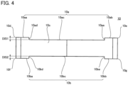
- Fig. 4 is a side view of cutting insert 10.
- cutting insert 10 has an upper surface 10a, a bottom surface 10b, and a side surface 10c.
- Upper surface 10a is a surface opposite to bottom surface 10b.
- Side surface 10c is contiguous to upper surface 10a and bottom surface 10b.
- Upper surface 10a has a corner portion 10aa, a corner portion 10ab, and a center portion 10ac when viewed in a plan view. Corner portion 10aa and corner portion 10ab are located at the corners of upper surface 10a when viewed in a plan view. Corner portion 10aa and corner portion 10ab are located at diagonal positions when viewed in a plan view. A ridgeline between corner portion 10aa and side surface 10c forms a cutting edge 10d, and a ridgeline between corner portion 10ab and side surface 10c forms a cutting edge 10e.
- Center portion 10ac is located adjacent to corner portion 10aa on a side opposite to cutting edge 10d when viewed in a plan view. From another viewpoint, it can be said that center portion 10ac is located adjacent to corner portion 10ab on a side opposite to cutting edge 10e. Upper surface 10a is depressed toward the bottom surface 10b side at center portion 10ac. As a result, a stepped surface 10ad exists between center portion 10ac and corner portion 10aa, and a stepped surface 10ae exists between center portion 10ac and corner portion 10ab.
- Bottom surface 10b has a corner portion 10ba, a corner portion 10bb, and a center portion 10bc when viewed in a plan view. Corner portion 10ba and corner portion 10bb are located at the corners of bottom surface 10b when viewed in a plan view. Corner portion 10ba and corner portion 10bb are located at diagonal positions when viewed in a plan view. A ridgeline between corner portion 10ba and side surface 10c forms a cutting edge 10f, and a ridgeline between corner portion 10bb and side surface 10c forms a cutting edge 10g.
- Center portion 10bc is located adjacent to corner portion 10ba on a side opposite to cutting edge 10f when viewed in a plan view. From another viewpoint, it can be said that center portion 10bc is located adjacent to corner portion 10bb on a side opposite to cutting edge 10g. Bottom surface 10b is depressed toward the upper surface 10a side at center portion 10bc. As a result, a stepped surface 10bd exists between center portion 10bc and corner portion 10ba, and a stepped surface 10be exists between center portion 10bc and corner portion 10bb.
- a distance between corner portion 10aa (corner portion 10ab) and center portion 10ac is defined as a distance DIS1.
- a distance between corner portion 10ba (corner portion 10bb) and center portion 10bc is defined as a distance DIS2.
- Distance DIS1 is equal to distance DIS2, for example.
- a through hole 10h, a through hole 10i, and a through hole 10j are formed in cutting insert 10.
- Each of through hole 10h, through hole 10i, and through hole 10j extends through cutting insert 10 along a direction from upper surface 10a toward bottom surface 10b (along the thickness direction of cutting insert 10).
- Each of through hole 10h, through hole 10i, and through hole 10j is formed in center portion 10ac (center portion 10bc).
- Through hole 10j is located at the center of cutting insert 10 when viewed in a plan view.
- Through hole 10h, through hole 10i, and through hole 10j are located on a diagonal line that connects the corner on the corner portion 10aa side to the corner on the corner portion 10ab side when viewed in a plan view.
- Through hole 10j exists between through hole 10h and through hole 10i when viewed in a plan view.
- Through hole 10h is located close to the corner on the corner portion 10aa side with respect to through hole 10j when viewed in a plan view.
- Through hole 10i is located close to the corner on the corner portion 10ab side with respect to through hole 10j when viewed in a plan view.
- the inner diameter of through hole 10j is larger than each of the inner diameter of through hole 10h and the inner diameter of through hole 10i.
- the inner diameter of through hole 10h is equal to the inner diameter of through hole 10i, for example.
- Fig. 5 is a perspective view of a cutting insert 10 according to a modification.
- cutting insert 10 may be constituted of a substrate 11, a cutting edge tip 12, a cutting edge tip 13, a cutting edge tip 14, and a cutting edge tip 15.
- a cutting edge 10d, a cutting edge 10e, a cutting edge 10f, and a cutting edge 10g are formed in cutting edge tip 12, cutting edge tip 13, cutting edge tip 14, and cutting edge tip 15, respectively.
- Substrate 11 is composed of, for example, a cemented carbide.
- Each of cutting edge tip 12, cutting edge tip 13, cutting edge tip 14, and cutting edge tip 15 is composed of, for example, a cubic boron nitride sintered material (a sintered material including cubic boron nitride grains and a binder).
- Each of cutting edge tip 12, cutting edge tip 13, cutting edge tip 14, and cutting edge tip 15 may be composed of a polycrystalline diamond sintered material (sintered material including diamond grains and a binder).
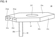
- Fig. 6 is a perspective view of coolant supply mechanism 20.
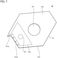
- Fig. 7 is a plan view of coolant supply mechanism 20.
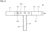
- Fig. 8 is a side view of coolant supply mechanism 20.
- coolant supply mechanism 20 has a main body portion 21 and a columnar portion 22.
- main body portion 21 and columnar portion 22 is preferably composed of a material having excellent thermal conductivity.
- main body portion 21 and columnar portion 22 is composed of, for example, a metal material.
- Main body portion 21 has an upper surface 21a, a bottom surface 21b, and a side surface 21c.
- Upper surface 21a is a surface opposite to bottom surface 21b.
- a distance between upper surface 21a and bottom surface 21b is defined as a distance DIS3.
- Distance DIS3 is larger than each of distance DIS1 and distance DIS2.
- a difference between distance DIS3 and distance DIS1 (distance DIS2) is, for example, less than 5 mm.
- the difference between distance DIS3 and distance DIS1 (distance DIS2) may be 1.5 mm or less.
- Side surface 21c is contiguous to upper surface 21a and bottom surface 21b.
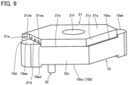
- Fig. 9 is a perspective view of coolant supply mechanism 20 when attached to cutting insert 10. As shown in Fig. 9 , when attached to cutting insert 10, bottom surface 21b is in contact with center portion 10ac. It should be noted that although not shown, bottom surface 21b may be in contact with center portion 10bc when attached to cutting insert 10.
- Side surface 21c has a first surface 21ca.
- First surface 21ca is in contact with stepped surface 10ad when attached to cutting insert 10.
- a portion of first surface 21ca in contact with stepped surface 10ad when attached to cutting insert 10 is defined as a first portion, and a portion of first surface 21ca not in contact with stepped surface 10ad when attached to cutting insert 10 is defined as a second portion.
- the second portion of first surface 21ca is located on the upper surface 21a side with respect to the first portion of first surface 21ca.
- first surface 21ca may be in contact with stepped surface 10ae when attached to cutting insert 10. It should be also noted that although not shown, in the case where bottom surface 21b is in contact with center portion 10bc when attached to cutting insert 10, first surface 21ca is in contact with one of stepped surface 10bd and stepped surface 10be.
- a coolant hole 21d is formed in the second portion of first surface 21ca.
- a plurality of coolant holes 21d may be formed. Since center portion 10ac is located adjacent to corner portion 10aa on the side opposite to cutting edge 10d and stepped surface 10ad is contiguous to center portion 10ac and corner portion 10aa, the first portion of first surface 21ca is in contact with stepped surface 10ad, with the result that coolant hole 21d faces cutting edge 10d and the coolant ejected from coolant hole 21d is supplied from the corner portion 10aa side (i.e., the rake surface side contiguous to cutting edge 10d) to cutting edge 10d.
- Side surface 21c further has a second surface 21cb.
- Second surface 21cb faces side surface 10c with a space being interposed therebetween.
- Second surface 21cb is contiguous to first surface 21ca.
- Coolant hole 21e is formed in second surface 21cb. Since second surface 21cb faces side surface 10c with a space being interposed therebetween, the coolant ejected from coolant hole 21e is supplied to side surface 10c (i.e., the flank face contiguous to cutting edge 10d).
- the number of coolant holes 21e is smaller than the number of coolant holes 21d, for example.
- the inner diameter of coolant hole 21e is preferably larger than the inner diameter of coolant hole 21d. It should be noted that when the shape of each of coolant hole 21d and coolant hole 21d is not a circular shape, each of the inner diameter of coolant hole 21d and the inner diameter of coolant hole 21e is measured along the direction from upper surface 21a toward bottom surface 21b. Further, the center position of coolant hole 21e is preferably located close to bottom surface 21b with respect to the center position of coolant hole 21d.
- a through hole 21f is formed in main body portion 21.
- Through hole 21f extends through main body portion 21 along the direction from upper surface 21a toward bottom surface 21b (along the thickness direction of main body portion 21).
- Through hole 21f is located at a position overlapping with through hole 10j when attached to cutting insert 10.
- Columnar portion 22 extends from bottom surface 21b along a direction intersecting bottom surface 21b (preferably, a direction orthogonal to bottom surface 21b). When attached to cutting insert 10, columnar portion 22 is inserted in through hole 10h. From another viewpoint, it can be said that columnar portion 22 is located between first surface 21ca and through hole 21f when viewed in a plan view. The tip of columnar portion 22 protrudes from bottom surface 10b (center portion 10bc) when attached to cutting insert 10.
- columnar portion 22 is inserted in through hole 10i. Further, in the case where bottom surface 21b is in contact with center portion 10bc, columnar portion 22 is inserted in through hole 10h when the first portion of first surface 21ca is in contact with stepped surface 10bd, and is inserted in through hole 10i when stepped surface 10be is in contact with the first portion of first surface 21ca.
- the inside of columnar portion 22 is preferably hollow. That is, a flow path 22a (indicated by a dotted line in Figs. 6 and 8 ) through which the coolant flows is formed inside columnar portion 22. A hollow portion 21g (indicated by a dotted line in Fig. 7 ) is formed inside main body portion 21. Flow path 22a is connected to hollow portion 21g. Coolant hole 21d and coolant hole 21e communicate with hollow portion 21g. Therefore, the coolant flowing through flow path 22a is ejected from coolant hole 21d and coolant hole 21e via hollow portion 21g.
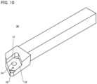
- Fig. 10 is a perspective view of holder 30.
- holder 30 has a pocket 31 at its tip.
- a protrusion 32 is formed on the bottom surface of pocket 31.
- Protrusion 32 has a shape conforming to a recess defined by center portion 10bc, stepped surface 10bd, and stepped surface 10be. Protrusion 32 is fitted in this recess when cutting insert 10 is attached to holder 30.
- a flow path 33 is formed inside holder 30. Coolant flows through flow path 33. One end of flow path 33 is opened at the bottom surface of pocket 31. Although not shown, the other end of flow path 33 is connected to a coolant supply pipe. When cutting insert 10 to which coolant supply mechanism 20 is attached is attached to holder 30, the tip of columnar portion 22 is connected to one end of flow path 33.
- Fixing member 40 is, for example, a screw. Fixing member 40 is inserted into through hole 10j and through hole 21f, and is screwed into screw hole 34. Thus, cutting insert 10 and coolant supply mechanism 20 are fastened and fixed to holder 30 (pocket 31).
- coolant supply mechanism 20 is attached to the recess defined by center portion 10ac, stepped surface 10ad, and stepped surface 10ae, an amount of protrusion of upper surface 21a from corner portion 10aa can be made small. As a result, according to cutting tool 100 using coolant supply mechanism 20, coolant supply mechanism 20 is less likely to interfere with a workpiece when performing inner-diameter processing.
- the coolant can also be supplied to the flank face side of cutting edge 10d.
- the coolant can be further readily supplied to the flank face side of cutting edge 10d.
Landscapes
- Engineering & Computer Science (AREA)
- Mechanical Engineering (AREA)
- Cutting Tools, Boring Holders, And Turrets (AREA)
Abstract
Description
- The present disclosure relates to a coolant supply mechanism.
- The cutting tool described in PTL 1 (
WO 2018/143089 ) has a holder, a cutting insert, and a clamping member. The cutting insert is disposed on a pocket of the holder. The clamping member is attached to the holder by a screw. A flow path through which coolant flows is formed inside the clamping member. The flow path formed inside the clamping member is opened at the tip of the clamping member, thereby forming a flow outlet via which the coolant is ejected. The tip side of the clamping member is in contact with the cutting insert, thus fixing the cutting insert to the holder. - PTL 1:
WO 2018/143089 - A coolant supply mechanism of the present disclosure is a coolant supply mechanism attachable to a cutting insert. The cutting insert has a first bottom surface, a first upper surface opposite to the first bottom surface, and a first side surface contiguous to the first bottom surface and the first upper surface. The first upper surface includes a corner portion that is located at a corner of the first upper surface when viewed in a plan view and that is contiguous to the first side surface so as to form a cutting edge, and a center portion located adjacent to the corner portion on a side opposite to the cutting edge when viewed in a plan view. The first upper surface is depressed toward the first bottom surface side at the center portion. The coolant supply mechanism includes a main body portion having a second bottom surface that is in contact with the center portion when attached to the cutting insert, a second upper surface opposite to the second bottom surface, and a second side surface contiguous to the second bottom surface and the second upper surface. The second side surface has a first surface including a first portion that is in contact with a stepped surface between the corner portion and the center portion when attached to the cutting insert, and a second portion that is located on the second upper surface side with respect to the first portion. The second portion is provided with a first coolant hole to eject coolant toward the cutting edge.
-
-
Fig. 1 is a perspective view of acutting tool 100. -
Fig. 2 is a plan view of acutting insert 10. -
Fig. 3 is a bottom view ofcutting insert 10. -
Fig. 4 is a side view ofcutting insert 10. -
Fig. 5 is a perspective view of a cutting insert 10 according to a modification. -
Fig. 6 is a perspective view of acoolant supply mechanism 20. -
Fig. 7 is a plan view ofcoolant supply mechanism 20. -
Fig. 8 is a side view ofcoolant supply mechanism 20. -
Fig. 9 is a perspective view ofcoolant supply mechanism 20 when attached to cuttinginsert 10. -
Fig. 10 is a perspective view of aholder 30. - In the cutting tool described in PTL 1, when the attachment position of the clamping member is deviated, a relative positional relation of the flow outlet of the clamping member with respect to the cutting edge of the cutting insert is also deviated. As a result, in the cutting tool described in PTL 1, the coolant cannot be precisely supplied to the cutting edge of the cutting insert.
- The present disclosure has been made in view of the above problem of the conventional art. More specifically, the present disclosure provides a coolant supply mechanism by which coolant can be precisely supplied to a cutting edge of a cutting insert.
- According to the coolant supply mechanism of the present disclosure, coolant can be precisely supplied to a cutting edge of a cutting insert.
- First, embodiments of the present disclosure are listed and described.
- (1) A coolant supply mechanism according to an embodiment is a coolant supply mechanism attachable to a cutting insert. The cutting insert has a first bottom surface, a first upper surface opposite to the first bottom surface, and a first side surface contiguous to the first bottom surface and the first upper surface. The first upper surface includes a corner portion that is located at a corner of the first upper surface when viewed in a plan view and that is contiguous to the first side surface so as to form a cutting edge, and a center portion located adjacent to the corner portion on a side opposite to the cutting edge when viewed in a plan view. The first upper surface is depressed toward the first bottom surface side at the center portion. The coolant supply mechanism includes a main body portion having a second bottom surface that is in contact with the center portion when attached to the cutting insert, a second upper surface opposite to the second bottom surface, and a second side surface contiguous to the second bottom surface and the second upper surface. The second side surface has a first surface including a first portion that is in contact with a stepped surface between the corner portion and the center portion when attached to the cutting insert, and a second portion that is located on the second upper surface side with respect to the first portion. The second portion is provided with a first coolant hole to eject coolant toward the cutting edge.
In the coolant supply mechanism of (1), the first coolant hole is positioned with respect to the cutting edge by the first surface being in contact with the stepped surface when attached to the cutting insert. Therefore, according to the coolant supply mechanism of (1), the coolant can be precisely supplied to the cutting edge of the cutting insert. - (2) The coolant supply mechanism of (1) may further include a columnar portion that extends from the second bottom surface along a direction intersecting the second bottom surface and that is inserted into a first through hole formed in the center portion so as to extend through the cutting insert along a direction from the first upper surface toward the second upper surface when attached to the cutting insert.
According to the coolant supply mechanism of (2), by inserting the columnar portion into the first through hole, positioning with respect to the cutting insert can be more readily performed. - (3) In the coolant supply mechanism of (2), inside of the columnar portion may be hollow. The coolant may be ejected from the first coolant hole through the inside of the columnar portion.
According to the coolant supply mechanism of (3), the coolant flows inside the columnar portion, thereby cooling the cutting insert. - (4) In the coolant supply mechanism of (3), the main body portion may be provided with a third through hole extending through the main body portion along a direction from the second upper surface toward the second bottom surface, the third through hole being located at a position overlapping with a second through hole formed in the center portion so as to extend through the cutting insert along a direction from the first upper surface toward the first bottom surface when attached to the cutting insert. The columnar portion may be located between the first surface and the third through hole when viewed in a plan view.
In the coolant supply mechanism of (4), when the coolant flows inside the columnar portion, the coolant can cool a portion of the cutting insert located closer to the cutting edge. Therefore, according to the coolant supply mechanism of (4), the effect of cooling the cutting insert can be further increased. - (5) In the coolant supply mechanism of (1) to (3), the second side surface may be provided with a second coolant hole to eject the coolant toward the first side surface.
According to the coolant supply mechanism of (5), the coolant can also be supplied to the flank face side of the cutting edge. - (6) In the coolant supply mechanism of (5), the second side surface may include a second surface facing the first side surface with a space being interpose between the second surface and the first side surface. The second coolant hole may be formed in the second surface.
- (7) In the coolant supply mechanism of (6), an inner diameter of the second coolant hole may be larger than an inner diameter of the first coolant hole.
- (8) In the coolant supply mechanism of (6), a center position of the second coolant hole may be located close to the second bottom surface with respect to a center position of the first coolant hole.
- Next, details of embodiments of the present disclosure will be described with reference to figures. In the figures described below, the same or corresponding components are denoted by the same reference characters, and the same explanation will not be made repeatedly.
- Hereinafter, a configuration of a cutting tool (hereinafter, referred to as "cutting
tool 100") according to an embodiment will be described. -
Fig. 1 is a perspective view of acutting tool 100. As shown inFig. 1 , cuttingtool 100 has a cuttinginsert 10, acoolant supply mechanism 20, aholder 30, and a fixingmember 40. - Cutting
insert 10 is composed of, for example, a cemented carbide.Fig. 2 is a plan view of cuttinginsert 10.Fig. 3 is a bottom view of cuttinginsert 10.Fig. 4 is a side view of cuttinginsert 10. As shown inFigs. 2 to 4 , cuttinginsert 10 has anupper surface 10a, abottom surface 10b, and aside surface 10c.Upper surface 10a is a surface opposite tobottom surface 10b.Side surface 10c is contiguous toupper surface 10a andbottom surface 10b. -
Upper surface 10a has a corner portion 10aa, a corner portion 10ab, and a center portion 10ac when viewed in a plan view. Corner portion 10aa and corner portion 10ab are located at the corners ofupper surface 10a when viewed in a plan view. Corner portion 10aa and corner portion 10ab are located at diagonal positions when viewed in a plan view. A ridgeline between corner portion 10aa andside surface 10c forms acutting edge 10d, and a ridgeline between corner portion 10ab andside surface 10c forms acutting edge 10e. - Center portion 10ac is located adjacent to corner portion 10aa on a side opposite to cutting
edge 10d when viewed in a plan view. From another viewpoint, it can be said that center portion 10ac is located adjacent to corner portion 10ab on a side opposite to cuttingedge 10e.Upper surface 10a is depressed toward thebottom surface 10b side at center portion 10ac. As a result, a stepped surface 10ad exists between center portion 10ac and corner portion 10aa, and a stepped surface 10ae exists between center portion 10ac and corner portion 10ab. -
Bottom surface 10b has a corner portion 10ba, a corner portion 10bb, and a center portion 10bc when viewed in a plan view. Corner portion 10ba and corner portion 10bb are located at the corners ofbottom surface 10b when viewed in a plan view. Corner portion 10ba and corner portion 10bb are located at diagonal positions when viewed in a plan view. A ridgeline between corner portion 10ba andside surface 10c forms acutting edge 10f, and a ridgeline between corner portion 10bb andside surface 10c forms acutting edge 10g. - Center portion 10bc is located adjacent to corner portion 10ba on a side opposite to cutting
edge 10f when viewed in a plan view. From another viewpoint, it can be said that center portion 10bc is located adjacent to corner portion 10bb on a side opposite to cuttingedge 10g.Bottom surface 10b is depressed toward theupper surface 10a side at center portion 10bc. As a result, a stepped surface 10bd exists between center portion 10bc and corner portion 10ba, and a stepped surface 10be exists between center portion 10bc and corner portion 10bb. - A distance between corner portion 10aa (corner portion 10ab) and center portion 10ac is defined as a distance DIS1. A distance between corner portion 10ba (corner portion 10bb) and center portion 10bc is defined as a distance DIS2. Distance DIS1 is equal to distance DIS2, for example.
- A through
hole 10h, a throughhole 10i, and a throughhole 10j are formed in cuttinginsert 10. Each of throughhole 10h, throughhole 10i, and throughhole 10j extends through cuttinginsert 10 along a direction fromupper surface 10a towardbottom surface 10b (along the thickness direction of cutting insert 10). Each of throughhole 10h, throughhole 10i, and throughhole 10j is formed in center portion 10ac (center portion 10bc). - Through
hole 10j is located at the center of cuttinginsert 10 when viewed in a plan view. Throughhole 10h, throughhole 10i, and throughhole 10j are located on a diagonal line that connects the corner on the corner portion 10aa side to the corner on the corner portion 10ab side when viewed in a plan view. Throughhole 10j exists between throughhole 10h and throughhole 10i when viewed in a plan view. - Through
hole 10h is located close to the corner on the corner portion 10aa side with respect to throughhole 10j when viewed in a plan view. Throughhole 10i is located close to the corner on the corner portion 10ab side with respect to throughhole 10j when viewed in a plan view. The inner diameter of throughhole 10j is larger than each of the inner diameter of throughhole 10h and the inner diameter of throughhole 10i. The inner diameter of throughhole 10h is equal to the inner diameter of throughhole 10i, for example. -
Fig. 5 is a perspective view of a cuttinginsert 10 according to a modification. As shown inFig. 5 , cuttinginsert 10 may be constituted of asubstrate 11, acutting edge tip 12, acutting edge tip 13, acutting edge tip 14, and acutting edge tip 15. Acutting edge 10d, acutting edge 10e, acutting edge 10f, and acutting edge 10g are formed in cuttingedge tip 12, cuttingedge tip 13, cuttingedge tip 14, and cuttingedge tip 15, respectively. -
Substrate 11 is composed of, for example, a cemented carbide. Each of cuttingedge tip 12, cuttingedge tip 13, cuttingedge tip 14, and cuttingedge tip 15 is composed of, for example, a cubic boron nitride sintered material (a sintered material including cubic boron nitride grains and a binder). Each of cuttingedge tip 12, cuttingedge tip 13, cuttingedge tip 14, and cuttingedge tip 15 may be composed of a polycrystalline diamond sintered material (sintered material including diamond grains and a binder). -
Fig. 6 is a perspective view ofcoolant supply mechanism 20.Fig. 7 is a plan view ofcoolant supply mechanism 20.Fig. 8 is a side view ofcoolant supply mechanism 20. As shown inFigs. 6 to 8 ,coolant supply mechanism 20 has amain body portion 21 and acolumnar portion 22. Each ofmain body portion 21 andcolumnar portion 22 is preferably composed of a material having excellent thermal conductivity. Each ofmain body portion 21 andcolumnar portion 22 is composed of, for example, a metal material. -
Main body portion 21 has anupper surface 21a, abottom surface 21b, and aside surface 21c.Upper surface 21a is a surface opposite tobottom surface 21b. A distance betweenupper surface 21a andbottom surface 21b is defined as a distance DIS3. Distance DIS3 is larger than each of distance DIS1 and distance DIS2. A difference between distance DIS3 and distance DIS1 (distance DIS2) is, for example, less than 5 mm. The difference between distance DIS3 and distance DIS1 (distance DIS2) may be 1.5 mm or less.Side surface 21c is contiguous toupper surface 21a andbottom surface 21b. -
Fig. 9 is a perspective view ofcoolant supply mechanism 20 when attached to cuttinginsert 10. As shown inFig. 9 , when attached to cuttinginsert 10,bottom surface 21b is in contact with center portion 10ac. It should be noted that although not shown,bottom surface 21b may be in contact with center portion 10bc when attached to cuttinginsert 10. -
Side surface 21c has a first surface 21ca. First surface 21ca is in contact with stepped surface 10ad when attached to cuttinginsert 10. A portion of first surface 21ca in contact with stepped surface 10ad when attached to cuttinginsert 10 is defined as a first portion, and a portion of first surface 21ca not in contact with stepped surface 10ad when attached to cuttinginsert 10 is defined as a second portion. The second portion of first surface 21ca is located on theupper surface 21a side with respect to the first portion of first surface 21ca. - It should be noted that although not shown, first surface 21ca may be in contact with stepped surface 10ae when attached to cutting
insert 10. It should be also noted that although not shown, in the case wherebottom surface 21b is in contact with center portion 10bc when attached to cuttinginsert 10, first surface 21ca is in contact with one of stepped surface 10bd and stepped surface 10be. - A
coolant hole 21d is formed in the second portion of first surface 21ca. A plurality ofcoolant holes 21d may be formed. Since center portion 10ac is located adjacent to corner portion 10aa on the side opposite to cuttingedge 10d and stepped surface 10ad is contiguous to center portion 10ac and corner portion 10aa, the first portion of first surface 21ca is in contact with stepped surface 10ad, with the result thatcoolant hole 21d faces cuttingedge 10d and the coolant ejected fromcoolant hole 21d is supplied from the corner portion 10aa side (i.e., the rake surface side contiguous to cuttingedge 10d) to cuttingedge 10d. -
Side surface 21c further has a second surface 21cb. Second surface 21cb facesside surface 10c with a space being interposed therebetween. Second surface 21cb is contiguous to first surface 21ca.Coolant hole 21e is formed in second surface 21cb. Since second surface 21cb facesside surface 10c with a space being interposed therebetween, the coolant ejected fromcoolant hole 21e is supplied toside surface 10c (i.e., the flank face contiguous to cuttingedge 10d). - The number of
coolant holes 21e is smaller than the number ofcoolant holes 21d, for example. The inner diameter ofcoolant hole 21e is preferably larger than the inner diameter ofcoolant hole 21d. It should be noted that when the shape of each ofcoolant hole 21d andcoolant hole 21d is not a circular shape, each of the inner diameter ofcoolant hole 21d and the inner diameter ofcoolant hole 21e is measured along the direction fromupper surface 21a towardbottom surface 21b. Further, the center position ofcoolant hole 21e is preferably located close tobottom surface 21b with respect to the center position ofcoolant hole 21d. - A through
hole 21f is formed inmain body portion 21. Throughhole 21f extends throughmain body portion 21 along the direction fromupper surface 21a towardbottom surface 21b (along the thickness direction of main body portion 21). Throughhole 21f is located at a position overlapping with throughhole 10j when attached to cuttinginsert 10. -
Columnar portion 22 extends frombottom surface 21b along a direction intersectingbottom surface 21b (preferably, a direction orthogonal tobottom surface 21b). When attached to cuttinginsert 10,columnar portion 22 is inserted in throughhole 10h. From another viewpoint, it can be said thatcolumnar portion 22 is located between first surface 21ca and throughhole 21f when viewed in a plan view. The tip ofcolumnar portion 22 protrudes frombottom surface 10b (center portion 10bc) when attached to cuttinginsert 10. - It should be noted that when the first portion of first surface 21ca is in contact with stepped surface 10ae,
columnar portion 22 is inserted in throughhole 10i. Further, in the case wherebottom surface 21b is in contact with center portion 10bc,columnar portion 22 is inserted in throughhole 10h when the first portion of first surface 21ca is in contact with stepped surface 10bd, and is inserted in throughhole 10i when stepped surface 10be is in contact with the first portion of first surface 21ca. - The inside of
columnar portion 22 is preferably hollow. That is, aflow path 22a (indicated by a dotted line inFigs. 6 and8 ) through which the coolant flows is formed insidecolumnar portion 22. Ahollow portion 21g (indicated by a dotted line inFig. 7 ) is formed insidemain body portion 21. Flowpath 22a is connected tohollow portion 21g.Coolant hole 21d andcoolant hole 21e communicate withhollow portion 21g. Therefore, the coolant flowing throughflow path 22a is ejected fromcoolant hole 21d andcoolant hole 21e viahollow portion 21g. -
Fig. 10 is a perspective view ofholder 30. As shown inFig. 10 ,holder 30 has apocket 31 at its tip. Aprotrusion 32 is formed on the bottom surface ofpocket 31.Protrusion 32 has a shape conforming to a recess defined by center portion 10bc, stepped surface 10bd, and stepped surface 10be.Protrusion 32 is fitted in this recess when cuttinginsert 10 is attached toholder 30. - A
flow path 33 is formed insideholder 30. Coolant flows throughflow path 33. One end offlow path 33 is opened at the bottom surface ofpocket 31. Although not shown, the other end offlow path 33 is connected to a coolant supply pipe. When cuttinginsert 10 to whichcoolant supply mechanism 20 is attached is attached toholder 30, the tip ofcolumnar portion 22 is connected to one end offlow path 33. - A
screw hole 34 is formed in the bottom surface ofpocket 31. Fixingmember 40 is, for example, a screw. Fixingmember 40 is inserted into throughhole 10j and throughhole 21f, and is screwed intoscrew hole 34. Thus, cuttinginsert 10 andcoolant supply mechanism 20 are fastened and fixed to holder 30 (pocket 31). - Hereinafter, effects of cutting
tool 100 will be described. - In cutting
tool 100, whencoolant supply mechanism 20 is attached to cuttinginsert 10, the first portion of first surface 21ca is in contact with stepped surface 10ad, with the result thatcoolant hole 21d formed in the second portion of first surface 21ca is positioned with respect to cuttingedge 10d. Therefore, according to cuttingtool 100 usingcoolant supply mechanism 20, coolant can be precisely supplied to cuttingedge 10d. - In cutting
tool 100, sincecoolant supply mechanism 20 is attached to the recess defined by center portion 10ac, stepped surface 10ad, and stepped surface 10ae, an amount of protrusion ofupper surface 21a from corner portion 10aa can be made small. As a result, according to cuttingtool 100 usingcoolant supply mechanism 20,coolant supply mechanism 20 is less likely to interfere with a workpiece when performing inner-diameter processing. - In cutting
tool 100, whencoolant supply mechanism 20 is attached to cuttinginsert 10,columnar portion 22 is inserted in throughhole 10h. Therefore, according to cuttingtool 100 usingcoolant supply mechanism 20, positioning is performed further readily when attachingcoolant supply mechanism 20 to cuttinginsert 10. - In cutting
tool 100, the coolant flowing through the inside of columnar portion 22 (flowpath 22a) cools cuttinginsert 10. Therefore, according to cuttingtool 100 usingcoolant supply mechanism 20, cooling of cuttinginsert 10 can be facilitated. Further, in cuttingtool 100,columnar portion 22 is inserted in throughhole 10h, with the result that the coolant flowing throughflow path 22a passes through a position close to cuttingedge 10d. Therefore, according to cuttingtool 100 usingcoolant supply mechanism 20, cuttinginsert 10 can be cooled at a portion close to cuttingedge 10d. - In cutting
tool 100, since the coolant is ejected fromcoolant hole 21e, the coolant can also be supplied to the flank face side of cuttingedge 10d. When the inner diameter ofcoolant hole 21e is larger than the inner diameter ofcoolant hole 21d or when the center position ofcoolant hole 21e is located close tobottom surface 21b with respect to the center position ofcoolant hole 21d, the coolant can be further readily supplied to the flank face side of cuttingedge 10d. - In cutting
tool 100, when cuttinginsert 10 is attached toholder 30,protrusion 32 is fitted in the recess defined by center portion 10bc, stepped surface 10bd, and stepped surface 10be, with the result that restraint strength for cuttinginsert 10 byholder 30 can be increased and precision in positioning of cuttinginsert 10 with respect toholder 30 can be increased. - The embodiments disclosed herein are illustrative and non-restrictive in any respect. The scope of the present invention is defined by the terms of the claims, rather than the embodiments described above, and is intended to include any modifications within the scope and meaning equivalent to the terms of the claims.
- 100: cutting tool; 10: cutting insert; 10a: upper surface; 10aa, 10ab: corner portion; 10ac: center portion; 10ad, 10ae: stepped surface; 10b: bottom surface; 10ba, 10bb: corner portion; 10bc: center portion; 10bd, 10be: stepped surface; 10bc: center portion; 10c: side surface; 10d, 10e, 10f, 10g: cutting edge; 10h, 10i, 10j: through hole; 11: substrate; 12, 13, 14, 15: cutting edge tip; 20: coolant supply mechanism; 21: main body portion; 21a: upper surface; 21b: bottom surface; 21c: side surface; 21ca: first surface; 21cb: second surface; 21d, 21e: coolant hole; 21f: through hole; 21g: hollow portion; 22: columnar portion; 22a: flow path; 30: holder; 31: pocket; 32: protrusion; 33: flow path; 34: screw hole; 40: fixing member; DIS1, DIS2, DIS3: distance.
Claims (8)
- A coolant supply mechanism attachable to a cutting insert, whereinthe cutting insert has a first bottom surface, a first upper surface opposite to the first bottom surface, and a first side surface contiguous to the first bottom surface and the first upper surface,the first upper surface includes a corner portion that is located at a corner of the first upper surface when viewed in a plan view and that is contiguous to the first side surface so as to form a cutting edge, and a center portion located adjacent to the corner portion on a side opposite to the cutting edge when viewed in a plan view, andthe first upper surface is depressed toward the first bottom surface side at the center portion,the coolant supply mechanism comprising a main body portion having a second bottom surface that is in contact with the center portion when attached to the cutting insert, a second upper surface opposite to the second bottom surface, and a second side surface contiguous to the second bottom surface and the second upper surface, whereinthe second side surface has a first surface including a first portion that is in contact with a stepped surface between the corner portion and the center portion when attached to the cutting insert, and a second portion that is located on the second upper surface side with respect to the first portion, andthe second portion is provided with a first coolant hole to eject coolant toward the cutting edge.
- The coolant supply mechanism according to claim 1, further comprising a columnar portion that extends from the second bottom surface along a direction intersecting the second bottom surface and that is inserted into a first through hole formed in the center portion so as to extend through the cutting insert along a direction from the first upper surface toward the second upper surface when attached to the cutting insert.
- The coolant supply mechanism according to claim 2, whereininside of the columnar portion is hollow, andthe coolant is ejected from the first coolant hole through the inside of the columnar portion.
- The coolant supply mechanism according to claim 3, whereinthe main body portion is provided with a third through hole extending through the main body portion along a direction from the second upper surface toward the second bottom surface, the third through hole being located at a position overlapping with a second through hole formed in the center portion so as to extend through the cutting insert along a direction from the first upper surface toward the first bottom surface when attached to the cutting insert, andthe columnar portion is located between the first surface and the third through hole when viewed in a plan view.
- The coolant supply mechanism according to any one of claims 1 to 4, wherein the second side surface is provided with a second coolant hole to eject the coolant toward the first side surface.
- The coolant supply mechanism according to claim 5, whereinthe second side surface further has a second surface facing the first side surface with a space being interposed between the second surface and the first side surface, andthe second coolant hole is formed in the second surface.
- The coolant supply mechanism according to claim 6, wherein an inner diameter of the second coolant hole is larger than an inner diameter of the first coolant hole.
- The coolant supply mechanism according to claim 6, wherein a center position of the second coolant hole is located close to the second bottom surface with respect to a center position of the first coolant hole.
Applications Claiming Priority (1)
| Application Number | Priority Date | Filing Date | Title |
|---|---|---|---|
| PCT/JP2020/023733 WO2021255851A1 (en) | 2020-06-17 | 2020-06-17 | Coolant supply mechanism |
Publications (2)
| Publication Number | Publication Date |
|---|---|
| EP4169642A1 true EP4169642A1 (en) | 2023-04-26 |
| EP4169642A4 EP4169642A4 (en) | 2023-08-02 |
Family
ID=79268701
Family Applications (1)
| Application Number | Title | Priority Date | Filing Date |
|---|---|---|---|
| EP20940809.5A Withdrawn EP4169642A4 (en) | 2020-06-17 | 2020-06-17 | COOLANT SUPPLY MECHANISM |
Country Status (5)
| Country | Link |
|---|---|
| US (1) | US20230219143A1 (en) |
| EP (1) | EP4169642A4 (en) |
| JP (1) | JPWO2021255851A1 (en) |
| CN (1) | CN115916436A (en) |
| WO (1) | WO2021255851A1 (en) |
Families Citing this family (2)
| Publication number | Priority date | Publication date | Assignee | Title |
|---|---|---|---|---|
| JP7185864B1 (en) * | 2022-07-22 | 2022-12-08 | 株式会社タンガロイ | Cutting tools |
| JP7449504B1 (en) | 2023-11-02 | 2024-03-14 | 株式会社タンガロイ | Cutting tool and its body |
Family Cites Families (46)
| Publication number | Priority date | Publication date | Assignee | Title |
|---|---|---|---|---|
| JPS5465084U (en) * | 1977-10-18 | 1979-05-09 | ||
| US4535216A (en) * | 1983-10-14 | 1985-08-13 | Rockwell International Corporation | Metal-working tool using electrical heating |
| SE504431C2 (en) * | 1994-06-29 | 1997-02-10 | Iggesund Tools Ab | Knife device |
| AU3323695A (en) * | 1994-08-09 | 1996-03-07 | Edison Materials Technology Center, The | Cryogenic machining |
| JPH09155604A (en) * | 1995-12-07 | 1997-06-17 | Sumitomo Electric Ind Ltd | Internal oiling type clamp bite |
| DE10208266A1 (en) * | 2001-07-26 | 2003-02-13 | Ceram Tec Ag Innovative Cerami | Stock-removing cutting tool has circular clamping trough with centre protrusion on cutting plate associated with matching circular ring on cam of pressure member which engages round protrusion |
| DE10239451A1 (en) * | 2002-08-28 | 2004-03-11 | Ceramtec Ag Innovative Ceramic Engineering | Cutting plate for mounting in a cutting tool for cutting cast material, especially cast iron, comprises a cutting plate upper side, a cutting edge |
| JP2006055917A (en) * | 2004-08-17 | 2006-03-02 | Tungaloy Corp | Throw-away cutter |
| SE528615C2 (en) * | 2005-05-02 | 2006-12-27 | Sandvik Intellectual Property | Threaded inserts with a downwardly open channel in the underside of the inserts |
| US7883299B2 (en) * | 2007-01-18 | 2011-02-08 | Kennametal Inc. | Metal cutting system for effective coolant delivery |
| US9101985B2 (en) * | 2007-01-18 | 2015-08-11 | Kennametal Inc. | Cutting insert assembly and components thereof |
| US8454274B2 (en) * | 2007-01-18 | 2013-06-04 | Kennametal Inc. | Cutting inserts |
| US7955032B2 (en) * | 2009-01-06 | 2011-06-07 | Kennametal Inc. | Cutting insert with coolant delivery and method of making the cutting insert |
| IL196439A (en) * | 2009-01-11 | 2013-04-30 | Iscar Ltd | A method for cutting alloys and cutting for them |
| SE0950092A1 (en) * | 2009-02-20 | 2010-06-08 | Seco Tools Ab | Cutting tools and cutters with fluid flow structures |
| JP5064476B2 (en) * | 2009-12-07 | 2012-10-31 | 株式会社菱興社 | Tool holder |
| US8734062B2 (en) * | 2010-09-02 | 2014-05-27 | Kennametal Inc. | Cutting insert assembly and components thereof |
| US9180650B2 (en) * | 2010-10-08 | 2015-11-10 | Kennametal Inc. | Cutting tool including an internal coolant system and fastener for a cutting tool including an internal coolant system |
| JP6006588B2 (en) * | 2012-09-04 | 2016-10-12 | 日本特殊陶業株式会社 | Cutting tool holder and cutting tool |
| EP2789415B1 (en) * | 2013-04-09 | 2022-06-08 | Seco Tools Ab | Toolholder with clamp having fluid flow passages, and tool including such a toolholder |
| US9427807B2 (en) * | 2013-05-13 | 2016-08-30 | Dennis P. Flolo | Clamp to hold a cutting insert on a tool holder |
| US9511421B2 (en) * | 2013-06-14 | 2016-12-06 | Kennametal Inc. | Cutting tool assembly having clamp assembly comprising a clamp and a coolant plate |
| US9895755B2 (en) * | 2014-12-09 | 2018-02-20 | Kennametal Inc. | Cutting insert with internal coolant passages and method of making same |
| DE102014119295B4 (en) * | 2014-12-19 | 2023-08-10 | Kennametal Inc. | Tool holder for a cutting insert and method for manufacturing the tool holder |
| RS62973B1 (en) * | 2015-01-09 | 2022-03-31 | Ceram Gmbh | Carrier tool |
| US10596634B2 (en) * | 2015-06-30 | 2020-03-24 | Seco Tools Ab | Cutting tool with a nozzle with a coolant channel |
| WO2017129413A1 (en) * | 2016-01-29 | 2017-08-03 | Seco Tools Ab | A cutting tool |
| JP2018012172A (en) * | 2016-07-21 | 2018-01-25 | 三菱マテリアル株式会社 | Tool bit |
| US10710166B2 (en) * | 2016-08-22 | 2020-07-14 | Kyocera Corporation | Cutting tool holder, cutting tool, and method of manufacturing machined product using them |
| US11890684B2 (en) * | 2016-12-01 | 2024-02-06 | Seco Tools Ab | Anvil with curved passage for cutting tool |
| DE112018000612B4 (en) | 2017-01-31 | 2025-04-03 | Kyocera Corporation | Cutting tool and method of manufacturing a machined product |
| AT15967U1 (en) * | 2017-05-19 | 2018-10-15 | Ceratizit Austria Gmbh | Clamping block for receiving a piercing blade |
| TWI640376B (en) * | 2017-06-30 | 2018-11-11 | Hsien-Jen Huang | Improved structure of the tool holder |
| KR20200020867A (en) * | 2017-07-27 | 2020-02-26 | 스미또모 덴꼬오 하드메탈 가부시끼가이샤 | Holder for cutting tool |
| JP6651136B2 (en) * | 2017-10-25 | 2020-02-19 | 株式会社タンガロイ | Cutting inserts, deposits and holders |
| DE202018100594U1 (en) * | 2018-02-02 | 2018-03-05 | Zcc Cutting Tools Europe Gmbh | Tool for machining |
| KR102393186B1 (en) * | 2018-03-28 | 2022-05-02 | 대구텍 유한책임회사 | Insert and cutting tool assembly comprising same |
| WO2019211043A1 (en) * | 2018-04-30 | 2019-11-07 | Hartmetall-Werkzeugfabrik Paul Horn Gmbh | Tool for machining a workpiece |
| DE202018006125U1 (en) * | 2018-04-30 | 2019-07-31 | Hartmetall-Werkzeugfabrik Paul Horn Gmbh | Tool for machining a workpiece |
| RS64015B1 (en) * | 2018-05-29 | 2023-03-31 | Ceram Gmbh | TOOL SYSTEM |
| EP3623083B1 (en) * | 2018-09-11 | 2022-11-09 | Walter Ag | Turning tool |
| EP3867001A1 (en) * | 2018-10-17 | 2021-08-25 | Hartmetall-Werkzeugfabrik Paul Horn GmbH | Tool holder and tool having a tool holder of this kind |
| JP7418960B2 (en) * | 2019-02-08 | 2024-01-22 | 国立大学法人東海国立大学機構 | Cutting inserts and cutting tools |
| JP6726395B2 (en) * | 2019-12-17 | 2020-07-22 | 株式会社タンガロイ | Cutting tools |
| US12202050B2 (en) * | 2021-12-29 | 2025-01-21 | Kennametal Inc. | Turning toolholder with enhanced coolant delivery system |
| JP7276980B1 (en) * | 2022-07-21 | 2023-05-18 | 住友電工ハードメタル株式会社 | Cutting tools |
-
2020
- 2020-06-17 EP EP20940809.5A patent/EP4169642A4/en not_active Withdrawn
- 2020-06-17 JP JP2022531163A patent/JPWO2021255851A1/ja not_active Ceased
- 2020-06-17 US US18/009,995 patent/US20230219143A1/en not_active Abandoned
- 2020-06-17 CN CN202080102126.3A patent/CN115916436A/en active Pending
- 2020-06-17 WO PCT/JP2020/023733 patent/WO2021255851A1/en not_active Ceased
Also Published As
| Publication number | Publication date |
|---|---|
| EP4169642A4 (en) | 2023-08-02 |
| WO2021255851A1 (en) | 2021-12-23 |
| JPWO2021255851A1 (en) | 2021-12-23 |
| CN115916436A (en) | 2023-04-04 |
| US20230219143A1 (en) | 2023-07-13 |
Similar Documents
| Publication | Publication Date | Title |
|---|---|---|
| EP3248721B1 (en) | Tool comprising a tool holder | |
| US11554427B2 (en) | Cutting insert and method for manufacturing cutting insert | |
| US10654116B2 (en) | Cutting insert, metal spacer and holder | |
| US9925596B2 (en) | Turning tool holder and cutting tool insert | |
| EP3408048B1 (en) | A cutting tool | |
| JP7091583B2 (en) | Cutting tool holder | |
| EP1722973B1 (en) | Cutting tool and associated tool head | |
| US20080003072A1 (en) | Indexable Type Cutting Tool | |
| EP2962795A1 (en) | Cutting insert, cutting tool, and method for manufacturing cut workpiece | |
| EP3593929B1 (en) | Cutting insert and milling tool | |
| JPWO2018143089A1 (en) | CUTTING TOOL AND PROCESS FOR PRODUCING CUT WORK | |
| JP2014018891A (en) | Cutting insert | |
| CN116133779B (en) | Grooving tools | |
| US20230219143A1 (en) | Coolant supply mechanism | |
| TW202202269A (en) | Light-weight tool holder with coolant cavity having varying cross-sectional area and cutting tool | |
| JP2006055916A (en) | Throw away type bite | |
| US11904393B1 (en) | External grooving insert holder having upper and lower jaws connected by angled hinge portion with cooling channel extending through hinge portion, and cutting tool | |
| CN103764324A (en) | Tool holders and cutting tools | |
| JP2006055917A (en) | Throw-away cutter | |
| EP3199273A1 (en) | A cutting tool | |
| US8641334B2 (en) | Insert | |
| JP2022155847A (en) | Boring bar | |
| US20180304387A1 (en) | Cutting tool and cutting insert | |
| JP2022154329A (en) | Coolant discharge member and tip-replaceable cutting tool | |
| JP2022154328A (en) | Coolant discharge member and tip-replaceable cutting tool |
Legal Events
| Date | Code | Title | Description |
|---|---|---|---|
| STAA | Information on the status of an ep patent application or granted ep patent |
Free format text: STATUS: THE INTERNATIONAL PUBLICATION HAS BEEN MADE |
|
| PUAI | Public reference made under article 153(3) epc to a published international application that has entered the european phase |
Free format text: ORIGINAL CODE: 0009012 |
|
| STAA | Information on the status of an ep patent application or granted ep patent |
Free format text: STATUS: REQUEST FOR EXAMINATION WAS MADE |
|
| 17P | Request for examination filed |
Effective date: 20221214 |
|
| AK | Designated contracting states |
Kind code of ref document: A1 Designated state(s): AL AT BE BG CH CY CZ DE DK EE ES FI FR GB GR HR HU IE IS IT LI LT LU LV MC MK MT NL NO PL PT RO RS SE SI SK SM TR |
|
| A4 | Supplementary search report drawn up and despatched |
Effective date: 20230630 |
|
| RIC1 | Information provided on ipc code assigned before grant |
Ipc: B23B 27/14 20060101ALI20230626BHEP Ipc: B23B 27/10 20060101AFI20230626BHEP |
|
| DAV | Request for validation of the european patent (deleted) | ||
| DAX | Request for extension of the european patent (deleted) | ||
| STAA | Information on the status of an ep patent application or granted ep patent |
Free format text: STATUS: THE APPLICATION HAS BEEN WITHDRAWN |
|
| 18W | Application withdrawn |
Effective date: 20241120 |