EP4169622B1 - Applicateur de produit de revêtement, installation d'application comprenant un tel applicateur et procédé d'application au moyen d'un tel applicateur - Google Patents
Applicateur de produit de revêtement, installation d'application comprenant un tel applicateur et procédé d'application au moyen d'un tel applicateur Download PDFInfo
- Publication number
- EP4169622B1 EP4169622B1 EP22213986.7A EP22213986A EP4169622B1 EP 4169622 B1 EP4169622 B1 EP 4169622B1 EP 22213986 A EP22213986 A EP 22213986A EP 4169622 B1 EP4169622 B1 EP 4169622B1
- Authority
- EP
- European Patent Office
- Prior art keywords
- applicator
- nozzles
- face
- faces
- printing nozzles
- Prior art date
- Legal status (The legal status is an assumption and is not a legal conclusion. Google has not performed a legal analysis and makes no representation as to the accuracy of the status listed.)
- Active
Links
Images

Classifications
-
- B—PERFORMING OPERATIONS; TRANSPORTING
- B05—SPRAYING OR ATOMISING IN GENERAL; APPLYING FLUENT MATERIALS TO SURFACES, IN GENERAL
- B05C—APPARATUS FOR APPLYING FLUENT MATERIALS TO SURFACES, IN GENERAL
- B05C5/00—Apparatus in which liquid or other fluent material is projected, poured or allowed to flow on to the surface of the work
- B05C5/02—Apparatus in which liquid or other fluent material is projected, poured or allowed to flow on to the surface of the work the liquid or other fluent material being discharged through an outlet orifice by pressure, e.g. from an outlet device in contact or almost in contact, with the work
- B05C5/027—Coating heads with several outlets, e.g. aligned transversally to the moving direction of a web to be coated
-
- B—PERFORMING OPERATIONS; TRANSPORTING
- B05—SPRAYING OR ATOMISING IN GENERAL; APPLYING FLUENT MATERIALS TO SURFACES, IN GENERAL
- B05C—APPARATUS FOR APPLYING FLUENT MATERIALS TO SURFACES, IN GENERAL
- B05C5/00—Apparatus in which liquid or other fluent material is projected, poured or allowed to flow on to the surface of the work
- B05C5/02—Apparatus in which liquid or other fluent material is projected, poured or allowed to flow on to the surface of the work the liquid or other fluent material being discharged through an outlet orifice by pressure, e.g. from an outlet device in contact or almost in contact, with the work
- B05C5/0291—Apparatus in which liquid or other fluent material is projected, poured or allowed to flow on to the surface of the work the liquid or other fluent material being discharged through an outlet orifice by pressure, e.g. from an outlet device in contact or almost in contact, with the work the material being discharged on the work through discrete orifices as discrete droplets, beads or strips that coalesce on the work or are spread on the work so as to form a continuous coating
-
- B—PERFORMING OPERATIONS; TRANSPORTING
- B41—PRINTING; LINING MACHINES; TYPEWRITERS; STAMPS
- B41J—TYPEWRITERS; SELECTIVE PRINTING MECHANISMS, i.e. MECHANISMS PRINTING OTHERWISE THAN FROM A FORME; CORRECTION OF TYPOGRAPHICAL ERRORS
- B41J2/00—Typewriters or selective printing mechanisms characterised by the printing or marking process for which they are designed
- B41J2/005—Typewriters or selective printing mechanisms characterised by the printing or marking process for which they are designed characterised by bringing liquid or particles selectively into contact with a printing material
- B41J2/01—Ink jet
- B41J2/135—Nozzles
- B41J2/14—Structure thereof only for on-demand ink jet heads
-
- B—PERFORMING OPERATIONS; TRANSPORTING
- B41—PRINTING; LINING MACHINES; TYPEWRITERS; STAMPS
- B41J—TYPEWRITERS; SELECTIVE PRINTING MECHANISMS, i.e. MECHANISMS PRINTING OTHERWISE THAN FROM A FORME; CORRECTION OF TYPOGRAPHICAL ERRORS
- B41J3/00—Typewriters or selective printing or marking mechanisms characterised by the purpose for which they are constructed
- B41J3/407—Typewriters or selective printing or marking mechanisms characterised by the purpose for which they are constructed for marking on special material
- B41J3/4073—Printing on three-dimensional objects not being in sheet or web form, e.g. spherical or cubic objects
-
- B—PERFORMING OPERATIONS; TRANSPORTING
- B05—SPRAYING OR ATOMISING IN GENERAL; APPLYING FLUENT MATERIALS TO SURFACES, IN GENERAL
- B05B—SPRAYING APPARATUS; ATOMISING APPARATUS; NOZZLES
- B05B13/00—Machines or plants for applying liquids or other fluent materials to surfaces of objects or other work by spraying, not covered by groups B05B1/00 - B05B11/00
- B05B13/02—Means for supporting work; Arrangement or mounting of spray heads; Adaptation or arrangement of means for feeding work
- B05B13/04—Means for supporting work; Arrangement or mounting of spray heads; Adaptation or arrangement of means for feeding work the spray heads being moved during spraying operation
- B05B13/0431—Means for supporting work; Arrangement or mounting of spray heads; Adaptation or arrangement of means for feeding work the spray heads being moved during spraying operation with spray heads moved by robots or articulated arms, e.g. for applying liquid or other fluent material to three-dimensional [3D] surfaces
-
- B—PERFORMING OPERATIONS; TRANSPORTING
- B05—SPRAYING OR ATOMISING IN GENERAL; APPLYING FLUENT MATERIALS TO SURFACES, IN GENERAL
- B05D—PROCESSES FOR APPLYING FLUENT MATERIALS TO SURFACES, IN GENERAL
- B05D1/00—Processes for applying liquids or other fluent materials
- B05D1/02—Processes for applying liquids or other fluent materials performed by spraying
-
- B—PERFORMING OPERATIONS; TRANSPORTING
- B25—HAND TOOLS; PORTABLE POWER-DRIVEN TOOLS; MANIPULATORS
- B25J—MANIPULATORS; CHAMBERS PROVIDED WITH MANIPULATION DEVICES
- B25J11/00—Manipulators not otherwise provided for
- B25J11/0075—Manipulators for painting or coating
-
- B—PERFORMING OPERATIONS; TRANSPORTING
- B25—HAND TOOLS; PORTABLE POWER-DRIVEN TOOLS; MANIPULATORS
- B25J—MANIPULATORS; CHAMBERS PROVIDED WITH MANIPULATION DEVICES
- B25J15/00—Gripping heads and other end effectors
- B25J15/0019—End effectors other than grippers
-
- B—PERFORMING OPERATIONS; TRANSPORTING
- B41—PRINTING; LINING MACHINES; TYPEWRITERS; STAMPS
- B41J—TYPEWRITERS; SELECTIVE PRINTING MECHANISMS, i.e. MECHANISMS PRINTING OTHERWISE THAN FROM A FORME; CORRECTION OF TYPOGRAPHICAL ERRORS
- B41J3/00—Typewriters or selective printing or marking mechanisms characterised by the purpose for which they are constructed
- B41J3/407—Typewriters or selective printing or marking mechanisms characterised by the purpose for which they are constructed for marking on special material
-
- B—PERFORMING OPERATIONS; TRANSPORTING
- B05—SPRAYING OR ATOMISING IN GENERAL; APPLYING FLUENT MATERIALS TO SURFACES, IN GENERAL
- B05B—SPRAYING APPARATUS; ATOMISING APPARATUS; NOZZLES
- B05B1/00—Nozzles, spray heads or other outlets, with or without auxiliary devices such as valves, heating means
- B05B1/02—Nozzles, spray heads or other outlets, with or without auxiliary devices such as valves, heating means designed to produce a jet, spray, or other discharge of particular shape or nature, e.g. in single drops, or having an outlet of particular shape
- B05B1/08—Nozzles, spray heads or other outlets, with or without auxiliary devices such as valves, heating means designed to produce a jet, spray, or other discharge of particular shape or nature, e.g. in single drops, or having an outlet of particular shape of pulsating nature, e.g. delivering liquid in successive separate quantities
- B05B1/083—Nozzles, spray heads or other outlets, with or without auxiliary devices such as valves, heating means designed to produce a jet, spray, or other discharge of particular shape or nature, e.g. in single drops, or having an outlet of particular shape of pulsating nature, e.g. delivering liquid in successive separate quantities the pulsating mechanism comprising movable parts
-
- B—PERFORMING OPERATIONS; TRANSPORTING
- B05—SPRAYING OR ATOMISING IN GENERAL; APPLYING FLUENT MATERIALS TO SURFACES, IN GENERAL
- B05B—SPRAYING APPARATUS; ATOMISING APPARATUS; NOZZLES
- B05B12/00—Arrangements for controlling delivery; Arrangements for controlling the spray area
- B05B12/02—Arrangements for controlling delivery; Arrangements for controlling the spray area for controlling time, or sequence, of delivery
- B05B12/04—Arrangements for controlling delivery; Arrangements for controlling the spray area for controlling time, or sequence, of delivery for sequential operation or multiple outlets
-
- B—PERFORMING OPERATIONS; TRANSPORTING
- B05—SPRAYING OR ATOMISING IN GENERAL; APPLYING FLUENT MATERIALS TO SURFACES, IN GENERAL
- B05B—SPRAYING APPARATUS; ATOMISING APPARATUS; NOZZLES
- B05B12/00—Arrangements for controlling delivery; Arrangements for controlling the spray area
- B05B12/16—Arrangements for controlling delivery; Arrangements for controlling the spray area for controlling the spray area
- B05B12/18—Arrangements for controlling delivery; Arrangements for controlling the spray area for controlling the spray area using fluids, e.g. gas streams
-
- B—PERFORMING OPERATIONS; TRANSPORTING
- B05—SPRAYING OR ATOMISING IN GENERAL; APPLYING FLUENT MATERIALS TO SURFACES, IN GENERAL
- B05B—SPRAYING APPARATUS; ATOMISING APPARATUS; NOZZLES
- B05B13/00—Machines or plants for applying liquids or other fluent materials to surfaces of objects or other work by spraying, not covered by groups B05B1/00 - B05B11/00
- B05B13/02—Means for supporting work; Arrangement or mounting of spray heads; Adaptation or arrangement of means for feeding work
- B05B13/04—Means for supporting work; Arrangement or mounting of spray heads; Adaptation or arrangement of means for feeding work the spray heads being moved during spraying operation
- B05B13/0447—Installation or apparatus for applying liquid or other fluent material to conveyed separate articles
- B05B13/0452—Installation or apparatus for applying liquid or other fluent material to conveyed separate articles the objects being vehicle components, e.g. vehicle bodies
-
- B—PERFORMING OPERATIONS; TRANSPORTING
- B05—SPRAYING OR ATOMISING IN GENERAL; APPLYING FLUENT MATERIALS TO SURFACES, IN GENERAL
- B05B—SPRAYING APPARATUS; ATOMISING APPARATUS; NOZZLES
- B05B15/00—Details of spraying plant or spraying apparatus not otherwise provided for; Accessories
- B05B15/60—Arrangements for mounting, supporting or holding spraying apparatus
- B05B15/65—Mounting arrangements for fluid connection of the spraying apparatus or its outlets to flow conduits
-
- B—PERFORMING OPERATIONS; TRANSPORTING
- B05—SPRAYING OR ATOMISING IN GENERAL; APPLYING FLUENT MATERIALS TO SURFACES, IN GENERAL
- B05B—SPRAYING APPARATUS; ATOMISING APPARATUS; NOZZLES
- B05B7/00—Spraying apparatus for discharge of liquids or other fluent materials from two or more sources, e.g. of liquid and air, of powder and gas
- B05B7/02—Spray pistols; Apparatus for discharge
- B05B7/04—Spray pistols; Apparatus for discharge with arrangements for mixing liquids or other fluent materials before discharge
- B05B7/0408—Spray pistols; Apparatus for discharge with arrangements for mixing liquids or other fluent materials before discharge with arrangements for mixing two or more liquids
-
- B—PERFORMING OPERATIONS; TRANSPORTING
- B41—PRINTING; LINING MACHINES; TYPEWRITERS; STAMPS
- B41J—TYPEWRITERS; SELECTIVE PRINTING MECHANISMS, i.e. MECHANISMS PRINTING OTHERWISE THAN FROM A FORME; CORRECTION OF TYPOGRAPHICAL ERRORS
- B41J2/00—Typewriters or selective printing mechanisms characterised by the printing or marking process for which they are designed
- B41J2/005—Typewriters or selective printing mechanisms characterised by the printing or marking process for which they are designed characterised by bringing liquid or particles selectively into contact with a printing material
- B41J2/01—Ink jet
- B41J2/135—Nozzles
- B41J2/14—Structure thereof only for on-demand ink jet heads
- B41J2002/14475—Structure thereof only for on-demand ink jet heads characterised by nozzle shapes or number of orifices per chamber
-
- B—PERFORMING OPERATIONS; TRANSPORTING
- B62—LAND VEHICLES FOR TRAVELLING OTHERWISE THAN ON RAILS
- B62D—MOTOR VEHICLES; TRAILERS
- B62D65/00—Designing, manufacturing, e.g. assembling, facilitating disassembly, or structurally modifying motor vehicles or trailers, not otherwise provided for
Definitions
- the present invention relates to a coating product applicator which comprises one of the printing nozzles each comprising an outlet channel opening downstream through a coating product ejection orifice.
- Paint application by means of print heads including print nozzles makes it possible to achieve a certain paint application precision.
- print heads can be mounted side-by-side and articulated or mounted adjustably relative to each other to follow the geometry of a surface to be coated.
- an applicator can carry several nozzles oriented differently and activated simultaneously to coat an internal surface of a concave object.
- He is also known to US-A-2011/0012961 to use a gantry placed above a conveyor transporting parts to be coated and equipped with plates which define product ejection orifices towards these parts.
- a nozzle is provided on an upper crosspiece and on each upright of the gantry. This equipment is bulky and could not be mounted on a vehicle body coating robot.
- a strip of paint applied to a body has clear edges along the axis of movement of the applicator but not at its ends.
- the start line of the application which corresponds to the activation zone of the print nozzles
- the finish line of the paint strip which corresponds to the stopping or deactivation of these nozzles, are jagged, that is to say they have irregularities.
- the robot can access the front part of the vehicle and then, after a period of time, the rear part.
- This mode of operation is not really compatible with the precise application of paint, to the extent that we wish to produce precisely defined strips along the conveyor axis.
- the vehicle's position over time is not defined precisely enough to create completely clear start and finish lines.
- the speed of the conveyor is not known very precisely, in particular because of the undulations due to the regulation and the movement of the conveyor drive motor.
- the multi-axis robot supporting the applicator must be equipped with a seventh robotic axis, in practice constituted by a rail for moving the robot along the axis of movement of the conveyor.
- This solution is also not precise enough with regard to the expected result. It is also expensive in terms of cycle time, as it requires positioning the robot on the front windshield area, before painting, and then repositioning the robot on the rear windshield area, also before painting.
- the present invention aims to solve these problems by proposing a new coating product applicator which allows both precise application of coating product, including at the starting and finishing lines of a strip or a another reason, while presenting a reduced cycle time compared to known solutions.
- the invention relates to a coating product applicator comprising printing nozzles each comprising an outlet channel opening downstream through a coating product ejection orifice.
- the printing nozzles are distributed over at least two faces of a body of the applicator, each nozzle belongs to a print head and the ejection orifices of these nozzles extend along at least two non-parallel planes .
- the print nozzles are controlled within the print heads such that the print nozzles mounted on a first face of the rigid body are activated independently of the print nozzles mounted on a second face of the rigid body, when the applicator is in operation
- the printing nozzles arranged on one side of the body of the applicator can be used for certain phases of application of coating product, for example parallel to the largest dimension of a strip of paint to be applied. apply to the roof of the bodywork of a motor vehicle, while the printing nozzles distributed on a second face of the same ejection nozzle applicator can be used to produce the start and finish lines of such tape, with great precision.
- the invention relates to an installation for applying a coating product to objects to be coated, which comprises at least one applicator as mentioned above, preferably mounted on the arm of a multi-axis robot designed to move it in relation to the objects to be coated.
- This process allows a coating product to be applied with great precision and quickly.
- the application distance between the ejection orifices of the active printing nozzles and the surface of an object being coated is between 5 and 50 mm. .
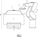
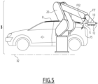
- Installation I shown in figures 1 , 4 And 5 is intended for the application of paint on objects O which, in the example of the figures, are motor vehicle bodies. More precisely, in this example, the installation I aims to allow the creation of a band B of contrasting color, for example black, on the roof of such a bodywork.
- the objects to be coated may be parts of motor vehicle bodies, for example bumpers or, more generally, any object that can be coated, for example a part of an aircraft cabin or a body of a household appliance. , these examples being not limiting.
- the installation I comprises a conveyor 2 designed to move the objects O along a conveyor axis X2 perpendicular to the plane of the figure 1 and parallel to the plans of figures 4 And 5 .
- Installation I also includes an applicator 10 mounted at the end of arm 22 of a multi-axis robot 20 placed in the vicinity of conveyor 2.
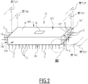
- the applicator 10 comprises several nozzles 12 which are identical to each other and which each belong to a print head 13.
- the applicator 10 comprises a body 14 which supports the nozzles 12 and which constitutes a rigid structural element allowing the nozzles 12 to be positioned in space.
- the body 14 is in one piece.
- the body 14 is parallelepiped 14 and defines a front face 142, a rear face 143 parallel to the front face 142, two longitudinal faces 144 and 145 parallel to each other and two transverse faces 146 and 147 parallel to each other.
- the front and rear faces 142 and 143 are perpendicular to the longitudinal faces 144 and 145, on the one hand, and to the transverse faces 146 and 147 on the other hand.
- the longitudinal faces 144 and 145 are, moreover, perpendicular to the transverse faces 146 and 147.
- the faces 144 to 147 are adjacent to the face 142.
- the front face 142 of the body 14 is turned towards an object to be coated when the applicator 10 works, to create the main part of a pattern, by applying a coating product to an object O.
- the nozzles 12 are rigidly mounted on the body 14. More precisely, four rows of sixteen nozzles 12 are arranged on the front face 142 of the body 14, these nozzles projecting from this front face which is flat.
- each nozzle 12 belongs to a print head 13 which further comprises a control member 132, for example of the piezoelectric component type, and a rod 134.
- Each nozzle 12 comprises a needle 122 controlled by the control member 132 of the print head 13 to which the nozzle belongs. Needle 122 is connected to component 132 by rod 134.
- the paint to be applied flows into a channel 16 provided in the body 14 and circulates, from one nozzle 12 to the other, in the direction of arrows F2.
- Channel 16 constitutes a common supply means for different nozzles 12 located on face 142 of applicator 10.
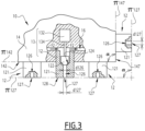
- 121 the part of a nozzle 12 which projects from one face of the body 14. Inside the part 121 of a nozzle, a seat 124 is provided against which the needle 122 of the nozzle comes selectively in support, being controlled by component 132.
- An outlet channel 126 is provided in each nozzle 12, downstream of its needle 122 and its seat 124. This outlet channel opens outwards, at opposite the needle 122, through an ejection orifice 127 provided in a front face 128 of the nozzle 12, more precisely in the front face 128 of its part 121.
- each nozzle 12 constitutes a printing nozzle intended to selectively eject paint through its ejection orifice 127.
- d126 the diameter of the outlet channel 126 of a nozzle 126 and d127 as the diameter of the ejection orifice 127 of this nozzle.
- d26 and d27 are equal.
- the diameter d127 is between 50 micrometers ( ⁇ m) and 500 ⁇ m, preferably between 100 and 200 ⁇ m, more preferably of the order of 150 ⁇ m.
- each nozzle 12 is capable of discharging from its ejection orifice 127, a succession of droplets G.
- these droplets G are represented as all emerging at the same time from the printing nozzles 12, which does not correspond to the process described below but makes it possible to identify the flow paths of these nozzles.
- ⁇ 142 the main plane of the front face 142 which is flat.
- ⁇ 127 the plane in which the ejection orifices 127 of the nozzles 12 arranged on the front face 142 are arranged.
- the planes ⁇ 142 and ⁇ 127 are parallel and the orifices 127 are themselves distributed on the front face 142, in the vicinity of this one.
- the transverse surface 147 is equipped with four nozzles 12 identical to those mounted on the front face 142, which constitute a row of printing nozzles and which also project relative to this surface 147, which is flat and of which we note ⁇ 147 the main plan.
- the ejection orifices 127 of the nozzles 12 mounted on the surface 147 extend in a plane ⁇ '127 parallel to the plane ⁇ 147 and can be considered as equally distributed on the surface 147, in the vicinity thereof.
- ⁇ 146 the transverse surface 146 which is flat and of which we denote ⁇ 146 as the main plane.
- the ejection orifices of these nozzles 12 extend in a plane ⁇ "127 parallel to the plane ⁇ 146. These orifices can be considered as equally distributed on the surface 146, in the vicinity of it
- the planes ⁇ 142 and ⁇ 147, on the one hand, ⁇ 142 and ⁇ 146, on the other hand, are not parallel to each other.
- the outlet orifices 127 of the nozzles respectively provided on the faces 142, 146 and 147 extend in at least two non-parallel dimensions.
- the applicator 10 can be described as a multi-nozzle-multi-dimension (MBMD) head. It constitutes a coating product applicator which allows to apply such a product with a high degree of precision, as emerges from the explanations which follow.
- MBMD multi-nozzle-multi-dimension
- ⁇ a defined angle, inside the body 14.10 between the planes ⁇ 142 and ⁇ 147.
- this angle ⁇ is equal to 90°.
- this angle ⁇ can be between 30° and 150°, preferably between 60 and 90°. Preferential values of this angle are 60°, 90° and 120°.
- the angle ⁇ is also the angle between the planes ⁇ 127 and ⁇ '127, measured on the side of these planes facing the body 14.
- the nozzles arranged 12 on the faces 142 and 147 which respectively eject paint perpendicular to the planes ⁇ 127 and ⁇ '127, make it possible to eject paint in two directions not parallel.
- the situation is the same for the printing nozzles 12 respectively located on the faces 142 and 146.
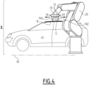
- the applicator 10 When it is necessary to create a strip B by forming patterns on the roof of a motor vehicle bodywork O, the applicator 10 is brought by the multi-axis robot 20 above the area of the roof to be coated, then the applicator 10 is moved parallel to the longitudinal axis of the bodywork, which is in practice parallel to the axis X2, as represented by arrows F4 and F4' at the Figure 4 .
- the nozzles 12 arranged on the front face 142 of the body 14 are activated.
- the needles 122 of these nozzles 12 are spaced from their seats 124 by the actuators 132 and the rods 134 of the corresponding print heads 13.
- the outlet channels 126 of these nozzles are supplied with paint and paint is ejected through their respective ejection orifices 127, which are in the plane ⁇ 127, towards the roof of the bodywork O, as represented by the droplets G which flow in the direction of arrows F42 at the Figure 4 .
- This printing technique makes it possible to constitute, on the roof of the vehicle, a strip B whose longitudinal edges, parallel to the direction of movement of the applicator according to arrows F4 and F4', are well defined and rectilinear.
- a first step consists of making the strip B by moving the applicator 10 in the direction of arrows F4 and F4' at the figure 4 , while supplying the nozzles 12 whose ejection orifices 127 are located in the plane ⁇ 127.
- the robot 20 brings the transverse face 147 of the applicator 10 facing the rear edge of the roof of the bodywork and moves this applicator 10 perpendicular to the axis X2, in the arrows F5 and F5' at the Figure 5 , while activating the nozzles 12 mounted on this transverse face 147, which has the effect of discharging droplets G of paint towards the edge of the roof from the ejection orifices 127 of these nozzles located in the plane ⁇ '127 , in the direction of arrow F52 at the Figure 5 .
- This makes it possible to form, at the rear end of strip B, a clean transverse border without serrations.
- An operation of the same type is then carried out, in the same second step of the process, at the level of the front edge of the border B, by activating the four nozzles 12 arranged on the transverse face 146 of the body 14, which eject paint through their ejection orifices 127 located in the plane ⁇ "127.
- the production of a transverse border can be carried out only at the front or only at the rear of the strip B.
- the application distance that is to say the distance measured between the ejection orifices 127 of the active printing nozzles 12 and the surface of the roof of the object O being coated, is advantageously between 5 and 50mm.
- This increases the paint transfer rate and reduces the distance of the overspray, i.e. the diffuse cloud of paint, from the footprint of the main spray, i.e. i.e. the cloud of paint directed directly onto the bodywork. This ensures that the uncontrolled drops G of paint are deposited as close as possible to the coverage zone of the main spray, therefore drops under control, intended to constitute band B.
- the nozzles 12 are completely integrated inside the body 14 of the applicator 10.
- the front surfaces 128 of the nozzles 12, in which the ejection orifices 127 are provided are related to the lateral faces of the body 14, in particular the front faces 142 and transverse faces 147 represented in the Figure 6 .
- the ⁇ 142 and ⁇ 127 planes are confused, as are the ⁇ 147 and ⁇ '127 planes.
- the planes ⁇ 142 and ⁇ 147 are not parallel, as are the planes ⁇ 127, ⁇ '127.
- the nozzles 12 respectively arranged on the surfaces 142 and 147 make it possible to eject paint in two non-parallel directions.
- the angle ⁇ defined as in the first embodiment is worth 120°.
- the printing nozzles 12 arranged on the face 142 are identical to each other and the printing nozzles 12 arranged on the face 147 are identical to each other, but the diameter d127 of the ejection orifices 127 of the nozzles printing 12 arranged on the surface 142 have a first value, while the diameter 127 of the orifices 127 of the nozzles 12 arranged on the surface 147 has a second value, less than the first value.
- ejection orifices 127 of the nozzles 12 arranged on the transverse face 147 are thinner than the ejection orifices 127 of the nozzles 12 arranged on the front face 142.
- the printing nozzles 12 arranged on the different faces of the body 14 are used at different times during the implementation of a coating product application process. This is why it is expected that the printing nozzles whose ejection orifices are distributed on two distinct faces of the body 14 are activated independently of each other, when the applicator 10 is in operation.
- a channel or channels common paint circulation(s) 16 is provided to supply the nozzles 12 mounted on the surface 142, while another comparable channel is provided to supply the nozzles 12 provided on the face 146 and yet another comparable channel is provided designed to supply the nozzles 12 provided on the face 147.
- the paint supply to these different channels is regulated by valves, preferably integrated into the body 14, controlled independently of each other.
- the different actuators 132 of the print heads 13 including the different nozzles 12 can be controlled independently of each other.
- a decorative hood strip can be made with a width of 100mm over a length of 1m, which corresponds to an area of 0.1m 2 , while covering an entire roof amounts to covering an area of approximately 2mx2m, or 4m 2 .
- the applicator 10 could therefore be selected according to the intended use.
- the applicator 10 is equipped with an interface 18 provided on its rear face 143 and allowing its rapid assembly/disassembly at the end of the arm 22 of the robot 20.
- This interface makes it possible to make a connection fluidic and electrical of the applicator 10 with the robot 20.
- the interface 10 can operate with a magnetic clipping system or by any other appropriate method.
- each applicator 10 is intended to apply paint with a flow rate belonging to a range of flow rates, therefore intended to coat a surface area included in a range of areas, during the time allocated to implement the method of the invention .
- This allows the robot 20 to load the applicator 10 best suited to the pattern to be produced on the vehicle body entering its work area.
- the applicator 10 is described in the case where printing nozzles 12 are provided on three faces of the body 14, namely the faces 142, 146 and 147.
- the nozzles 12 can be provided on only two of these faces or, on the contrary, on four, five or six of these faces, it being specified here that, preferably, the rear face 143 is not equipped with nozzles 12.
- the invention is described above in the case of the application of paint to a motor vehicle body. It is particularly suitable for the application of “base coat” type paint, that is to say a layer of color with or without effect, as well as the application of one- or two-component varnish. The application of a primer is also possible.
- the applicator 10 can be used to apply ink or any other coating product.
- a static mixer is integrated into the installation I, more precisely inside the body 14, on the path of the channel 16 , just upstream of nozzles 12.
- additional guide air can be brought to the level of the front face 128 of each nozzle 12 in order to contain the drops G leaving the ejection orifices 127.
- This additional guide air can be ejected in the form of an air blade, i.e. an air curtain acting as a boundary that G droplets cannot cross, an air ring or several air jets shaped with a vortex shape, converging or diverging in the direction of the axis of the outlet channel 126 of each nozzle.
- This additional guide air can be brought to the vicinity of nozzles 12 individually or for a group of nozzles, for example, a line of nozzles, a column of nozzles or a matrix of nozzles, or even in a grouped manner for all the nozzles arranged on one face of the body 14 the applicator 10.
- an electrostatic charging system for the applied coating product can be provided, this system being with internal charge and/or external charge, which makes it possible to accelerate the drops G leaving the ejection orifices 127 and deposit them on the surface to be coated which is connected to the mass.
- Such an electrostatic system can be provided individually for each nozzle 12, for a group of nozzles, for example by row, by column or for a matrix of nozzles or in the form of a single electrostatic system provided for all the nozzles of the applicator 10.
- nozzles 12 are indicative. Alternatively, they may be different.
- several printing nozzles 12 are provided on a first face of the body 14, for example the face 142, to be used during the first step of the process. These nozzles are preferably arranged in rows and columns.
- One or more nozzles are provided on another face, for example face 146 or 147, for the second stage.
- the number of nozzles provided on the first face of the body 14 is different, in practice greater, than the number of nozzles provided on the other face.
- the body 14 of the applicator 10 can be supported by a device other than a multi-axis robot, provided that this device makes it possible to implement the two stages of the method of the invention.
- a cross table can be used for an application on parallelepiped objects
- the installation I comprises several applicators 10.
- the body 14 may have a shape other than parallelepiped.
- the body 14 can be formed of several parts assembled rigidly, that is to say without the possibility of relative movement between them.
- the main planes ⁇ 142, ⁇ 146 and ⁇ 147 are defined as average planes of these faces, as are the planes ⁇ 127, ⁇ '127 and ⁇ "127. This is particularly the case if the applicator is used to apply paint or varnish to door frames or surrounds, which may have a section having several sides connected by rays which can be painted at the same time.
- the invention is described above during its implementation for the creation of a band. However, it is applicable for the creation of other patterns on any object to be coated.
Landscapes
- Engineering & Computer Science (AREA)
- Robotics (AREA)
- Mechanical Engineering (AREA)
- Manufacturing & Machinery (AREA)
- Coating Apparatus (AREA)
- Application Of Or Painting With Fluid Materials (AREA)
- Spray Control Apparatus (AREA)
Applications Claiming Priority (2)
| Application Number | Priority Date | Filing Date | Title |
|---|---|---|---|
| FR1904218A FR3095132B1 (fr) | 2019-04-19 | 2019-04-19 | Applicateur de produit de revêtement, installation d’application comprenant un tel applicateur et procédé d’application au moyen d’un tel applicateur |
| EP20170084.6A EP3725419B1 (fr) | 2019-04-19 | 2020-04-17 | Applicateur de produit de revêtement, installation d'application comprenant un tel applicateur et procédé d'application au moyen d'un tel applicateur |
Related Parent Applications (2)
| Application Number | Title | Priority Date | Filing Date |
|---|---|---|---|
| EP20170084.6A Division EP3725419B1 (fr) | 2019-04-19 | 2020-04-17 | Applicateur de produit de revêtement, installation d'application comprenant un tel applicateur et procédé d'application au moyen d'un tel applicateur |
| EP20170084.6A Division-Into EP3725419B1 (fr) | 2019-04-19 | 2020-04-17 | Applicateur de produit de revêtement, installation d'application comprenant un tel applicateur et procédé d'application au moyen d'un tel applicateur |
Publications (2)
| Publication Number | Publication Date |
|---|---|
| EP4169622A1 EP4169622A1 (fr) | 2023-04-26 |
| EP4169622B1 true EP4169622B1 (fr) | 2024-03-13 |
Family
ID=67810827
Family Applications (2)
| Application Number | Title | Priority Date | Filing Date |
|---|---|---|---|
| EP22213986.7A Active EP4169622B1 (fr) | 2019-04-19 | 2020-04-17 | Applicateur de produit de revêtement, installation d'application comprenant un tel applicateur et procédé d'application au moyen d'un tel applicateur |
| EP20170084.6A Active EP3725419B1 (fr) | 2019-04-19 | 2020-04-17 | Applicateur de produit de revêtement, installation d'application comprenant un tel applicateur et procédé d'application au moyen d'un tel applicateur |
Family Applications After (1)
| Application Number | Title | Priority Date | Filing Date |
|---|---|---|---|
| EP20170084.6A Active EP3725419B1 (fr) | 2019-04-19 | 2020-04-17 | Applicateur de produit de revêtement, installation d'application comprenant un tel applicateur et procédé d'application au moyen d'un tel applicateur |
Country Status (8)
| Country | Link |
|---|---|
| US (1) | US11731158B2 (enExample) |
| EP (2) | EP4169622B1 (enExample) |
| JP (2) | JP2020175384A (enExample) |
| KR (1) | KR102881703B1 (enExample) |
| CN (1) | CN111822233B (enExample) |
| ES (2) | ES2985228T3 (enExample) |
| FR (1) | FR3095132B1 (enExample) |
| RU (1) | RU2020113771A (enExample) |
Families Citing this family (8)
| Publication number | Priority date | Publication date | Assignee | Title |
|---|---|---|---|---|
| EP4023344B1 (en) * | 2019-08-30 | 2025-11-12 | Kyocera Corporation | Painting device, painted film, and painting method |
| FR3115716B1 (fr) * | 2020-11-05 | 2023-12-22 | Exel Ind | Procede et installation d’application d’un produit de revetement sur une surface |
| CN113070191B (zh) * | 2021-05-12 | 2021-09-28 | 广州信邦智能装备股份有限公司 | 一种汽车前后挡风玻璃自动涂胶机 |
| CN113510054B (zh) * | 2021-06-22 | 2022-12-02 | 机械工业第九设计研究院股份有限公司 | 一种多胶品集成涂胶机器人系统 |
| CN113492082A (zh) * | 2021-06-30 | 2021-10-12 | 镭德杰标识科技武汉有限公司 | 喷涂装置、赋码系统及涂层喷涂方法 |
| DE102021121060A1 (de) | 2021-08-13 | 2023-02-16 | Bayerische Motoren Werke Aktiengesellschaft | Applikationskopf, Applikationsvorrichtung sowie Fahrzeugteil |
| CA3241524A1 (en) * | 2021-12-23 | 2023-06-29 | Robert K. ROOP | Method and system for painting an object |
| JP2023140457A (ja) * | 2022-03-23 | 2023-10-05 | 株式会社リコー | 液体吐出システム |
Family Cites Families (15)
| Publication number | Priority date | Publication date | Assignee | Title |
|---|---|---|---|---|
| JP3754632B2 (ja) * | 2000-06-26 | 2006-03-15 | Abb株式会社 | ツートーン塗装方法 |
| US6582766B2 (en) * | 2000-06-26 | 2003-06-24 | Abb K.K. | Two-tone coating method |
| JP2003251813A (ja) * | 2002-03-06 | 2003-09-09 | Ricoh Co Ltd | インクジェットヘッド、インクジェット記録装置及び積層型圧電素子 |
| JP2007230849A (ja) * | 2006-03-03 | 2007-09-13 | Nippon Sheet Glass Co Ltd | ガラス板端部の塗布方法、ガラス板端部の塗布装置、及びそのガラス板端部の塗布方法により端部が被覆されたガラス板 |
| EP1884365A1 (en) * | 2006-07-28 | 2008-02-06 | Abb Research Ltd. | Paint applicator and coating method |
| ITMO20070134A1 (it) * | 2007-04-17 | 2008-10-18 | Gruppo Barbieri & Tarozzi S P A | "metodo ed impianto di decoro per decorare manufatti ceramici" |
| CN101939171A (zh) * | 2007-12-31 | 2011-01-05 | 埃克阿泰克有限责任公司 | 用于打印三维物品的装置和方法 |
| DE102008053178A1 (de) * | 2008-10-24 | 2010-05-12 | Dürr Systems GmbH | Beschichtungseinrichtung und zugehöriges Beschichtungsverfahren |
| WO2010141699A2 (en) | 2009-06-04 | 2010-12-09 | E. I. Du Pont De Nemours And Company | Multicolor electronic devices and processes of forming the same by printing |
| CN101954327A (zh) * | 2009-07-14 | 2011-01-26 | 鸿富锦精密工业(深圳)有限公司 | 立体喷墨头 |
| ES2582727T3 (es) * | 2013-09-12 | 2016-09-14 | Agfa Graphics Nv | Impresión por inyección de tintas sobre un objeto con forma de cuboide y de gran tamaño |
| PL3047003T3 (pl) | 2013-09-16 | 2021-05-04 | Basf Se | Zastosowanie zmodyfikowanych kwasów poliasparaginowych w środkach do zmywania |
| US10220408B2 (en) * | 2016-09-12 | 2019-03-05 | The Boeing Company | Variable radius print head end effector |
| FR3060420B1 (fr) | 2016-12-15 | 2024-01-05 | Exel Ind | Tete d'application d'un produit de revetement sur une surface a revetir et systeme d'application comprenant cette tete d'application |
| DE102019102088A1 (de) * | 2018-01-30 | 2019-08-01 | Ford Global Technologies, Llc | Verbundstoffultraschallmaterialapplikatoren mit einzeln ansteuerbaren mikroapplikatoren und verfahren der verwendung von diesen |
-
2019
- 2019-04-19 FR FR1904218A patent/FR3095132B1/fr active Active
-
2020
- 2020-04-13 JP JP2020071510A patent/JP2020175384A/ja active Pending
- 2020-04-13 CN CN202010286889.XA patent/CN111822233B/zh active Active
- 2020-04-14 KR KR1020200045266A patent/KR102881703B1/ko active Active
- 2020-04-17 EP EP22213986.7A patent/EP4169622B1/fr active Active
- 2020-04-17 ES ES22213986T patent/ES2985228T3/es active Active
- 2020-04-17 RU RU2020113771A patent/RU2020113771A/ru unknown
- 2020-04-17 EP EP20170084.6A patent/EP3725419B1/fr active Active
- 2020-04-17 US US16/851,927 patent/US11731158B2/en active Active
- 2020-04-17 ES ES20170084T patent/ES2977904T3/es active Active
-
2024
- 2024-12-03 JP JP2024210740A patent/JP2025026501A/ja active Pending
Also Published As
| Publication number | Publication date |
|---|---|
| ES2985228T3 (es) | 2024-11-04 |
| US11731158B2 (en) | 2023-08-22 |
| US20200331023A1 (en) | 2020-10-22 |
| EP4169622A1 (fr) | 2023-04-26 |
| EP3725419A1 (fr) | 2020-10-21 |
| CN111822233A (zh) | 2020-10-27 |
| KR102881703B1 (ko) | 2025-11-05 |
| JP2025026501A (ja) | 2025-02-21 |
| RU2020113771A (ru) | 2021-10-18 |
| KR20200123012A (ko) | 2020-10-28 |
| CN111822233B (zh) | 2023-07-28 |
| JP2020175384A (ja) | 2020-10-29 |
| EP3725419B1 (fr) | 2024-03-13 |
| FR3095132B1 (fr) | 2021-05-07 |
| ES2977904T3 (es) | 2024-09-02 |
| FR3095132A1 (fr) | 2020-10-23 |
Similar Documents
| Publication | Publication Date | Title |
|---|---|---|
| EP4169622B1 (fr) | Applicateur de produit de revêtement, installation d'application comprenant un tel applicateur et procédé d'application au moyen d'un tel applicateur | |
| EP3213823B1 (fr) | Applicateur de produit de revetement, robot multiaxes comprenant un tel applicateur et procede d'application d'un produit de revetement | |
| EP3335801B1 (fr) | Tête d'application d'un produit de revêtement sur une surface à revêtir et système d'application comprenant cette tête d'application | |
| EP1303359B1 (fr) | Procede et station de changement de produit dans une installation de projection de produit de revetement | |
| EP2429716B1 (fr) | Projecteur et organe de pulverisation de produit de revetement et procede de projection mettant en oeuvre un tel projecteur | |
| EP3725421B1 (fr) | Installation d'application de produit de revêtement et procédé de nettoyage d'une telle installation | |
| EP3643409A1 (fr) | Procédé d'application d'un produit de revêtement suivant la technologie de goutte à la demande et robot applicateur pour la mise en oeuvre du procédé | |
| EP3995315B1 (fr) | Procédé et installation d'application d'un produit de revêtement sur une surface | |
| EP3774368A1 (fr) | Méthode et dispositif pour former un motif de matière | |
| EP3269454B2 (fr) | Jupe comprenant au moins trois séries de buses d'éjection d'air distinctes, projecteur rotatif de produit de revêtement avec une telle jupe et son procédé d'utilisation | |
| WO2020089242A1 (fr) | Bol de pulvérisation de produit de revêtement, projecteur rotatif incluant un tel bol et procédé de nettoyage d'un tel projecteur | |
| FR3085619A1 (fr) | Procede d'impression par jet d'encre d'un motif sur une surface en matiere plastique | |
| FR3008004A1 (fr) | Procede et installation de traitement d'une surface d'un objet en polymere | |
| EP3012109A1 (fr) | Ensemble d'un objet à anse et d'une machine à jet d'encre pour imprimer l'objet | |
| EP4261042B1 (fr) | Tête d'impression comprenant un circuit de maintenance et installation de revêtement | |
| FR3062595A1 (fr) | Procede d'impression d'une piece transparente ou translucide et piece obtenue |
Legal Events
| Date | Code | Title | Description |
|---|---|---|---|
| PUAI | Public reference made under article 153(3) epc to a published international application that has entered the european phase |
Free format text: ORIGINAL CODE: 0009012 |
|
| STAA | Information on the status of an ep patent application or granted ep patent |
Free format text: STATUS: REQUEST FOR EXAMINATION WAS MADE |
|
| 17P | Request for examination filed |
Effective date: 20221215 |
|
| AC | Divisional application: reference to earlier application |
Ref document number: 3725419 Country of ref document: EP Kind code of ref document: P |
|
| AK | Designated contracting states |
Kind code of ref document: A1 Designated state(s): AL AT BE BG CH CY CZ DE DK EE ES FI FR GB GR HR HU IE IS IT LI LT LU LV MC MK MT NL NO PL PT RO RS SE SI SK SM TR |
|
| GRAP | Despatch of communication of intention to grant a patent |
Free format text: ORIGINAL CODE: EPIDOSNIGR1 |
|
| STAA | Information on the status of an ep patent application or granted ep patent |
Free format text: STATUS: GRANT OF PATENT IS INTENDED |
|
| RIC1 | Information provided on ipc code assigned before grant |
Ipc: B05B 13/04 20060101ALN20230914BHEP Ipc: B05B 15/65 20180101ALN20230914BHEP Ipc: B05B 1/08 20060101ALN20230914BHEP Ipc: B05B 7/04 20060101ALN20230914BHEP Ipc: B05B 12/18 20180101ALN20230914BHEP Ipc: B25J 9/00 20060101ALI20230914BHEP Ipc: B41J 3/407 20060101ALI20230914BHEP Ipc: B05B 12/04 20060101AFI20230914BHEP |
|
| INTG | Intention to grant announced |
Effective date: 20231018 |
|
| GRAS | Grant fee paid |
Free format text: ORIGINAL CODE: EPIDOSNIGR3 |
|
| GRAA | (expected) grant |
Free format text: ORIGINAL CODE: 0009210 |
|
| STAA | Information on the status of an ep patent application or granted ep patent |
Free format text: STATUS: THE PATENT HAS BEEN GRANTED |
|
| AC | Divisional application: reference to earlier application |
Ref document number: 3725419 Country of ref document: EP Kind code of ref document: P |
|
| AK | Designated contracting states |
Kind code of ref document: B1 Designated state(s): AL AT BE BG CH CY CZ DE DK EE ES FI FR GB GR HR HU IE IS IT LI LT LU LV MC MK MT NL NO PL PT RO RS SE SI SK SM TR |
|
| REG | Reference to a national code |
Ref country code: GB Ref legal event code: FG4D Free format text: NOT ENGLISH |
|
| REG | Reference to a national code |
Ref country code: CH Ref legal event code: EP |
|
| REG | Reference to a national code |
Ref country code: DE Ref legal event code: R096 Ref document number: 602020027375 Country of ref document: DE |
|
| REG | Reference to a national code |
Ref country code: IE Ref legal event code: FG4D Free format text: LANGUAGE OF EP DOCUMENT: FRENCH |
|
| PG25 | Lapsed in a contracting state [announced via postgrant information from national office to epo] |
Ref country code: LT Free format text: LAPSE BECAUSE OF FAILURE TO SUBMIT A TRANSLATION OF THE DESCRIPTION OR TO PAY THE FEE WITHIN THE PRESCRIBED TIME-LIMIT Effective date: 20240313 |
|
| REG | Reference to a national code |
Ref country code: LT Ref legal event code: MG9D |
|
| PG25 | Lapsed in a contracting state [announced via postgrant information from national office to epo] |
Ref country code: GR Free format text: LAPSE BECAUSE OF FAILURE TO SUBMIT A TRANSLATION OF THE DESCRIPTION OR TO PAY THE FEE WITHIN THE PRESCRIBED TIME-LIMIT Effective date: 20240614 |
|
| REG | Reference to a national code |
Ref country code: NL Ref legal event code: MP Effective date: 20240313 |
|
| PG25 | Lapsed in a contracting state [announced via postgrant information from national office to epo] |
Ref country code: RS Free format text: LAPSE BECAUSE OF FAILURE TO SUBMIT A TRANSLATION OF THE DESCRIPTION OR TO PAY THE FEE WITHIN THE PRESCRIBED TIME-LIMIT Effective date: 20240613 Ref country code: HR Free format text: LAPSE BECAUSE OF FAILURE TO SUBMIT A TRANSLATION OF THE DESCRIPTION OR TO PAY THE FEE WITHIN THE PRESCRIBED TIME-LIMIT Effective date: 20240313 |
|
| PG25 | Lapsed in a contracting state [announced via postgrant information from national office to epo] |
Ref country code: RS Free format text: LAPSE BECAUSE OF FAILURE TO SUBMIT A TRANSLATION OF THE DESCRIPTION OR TO PAY THE FEE WITHIN THE PRESCRIBED TIME-LIMIT Effective date: 20240613 Ref country code: NO Free format text: LAPSE BECAUSE OF FAILURE TO SUBMIT A TRANSLATION OF THE DESCRIPTION OR TO PAY THE FEE WITHIN THE PRESCRIBED TIME-LIMIT Effective date: 20240613 Ref country code: LT Free format text: LAPSE BECAUSE OF FAILURE TO SUBMIT A TRANSLATION OF THE DESCRIPTION OR TO PAY THE FEE WITHIN THE PRESCRIBED TIME-LIMIT Effective date: 20240313 Ref country code: HR Free format text: LAPSE BECAUSE OF FAILURE TO SUBMIT A TRANSLATION OF THE DESCRIPTION OR TO PAY THE FEE WITHIN THE PRESCRIBED TIME-LIMIT Effective date: 20240313 Ref country code: GR Free format text: LAPSE BECAUSE OF FAILURE TO SUBMIT A TRANSLATION OF THE DESCRIPTION OR TO PAY THE FEE WITHIN THE PRESCRIBED TIME-LIMIT Effective date: 20240614 Ref country code: FI Free format text: LAPSE BECAUSE OF FAILURE TO SUBMIT A TRANSLATION OF THE DESCRIPTION OR TO PAY THE FEE WITHIN THE PRESCRIBED TIME-LIMIT Effective date: 20240313 Ref country code: BG Free format text: LAPSE BECAUSE OF FAILURE TO SUBMIT A TRANSLATION OF THE DESCRIPTION OR TO PAY THE FEE WITHIN THE PRESCRIBED TIME-LIMIT Effective date: 20240313 |
|
| REG | Reference to a national code |
Ref country code: AT Ref legal event code: MK05 Ref document number: 1665255 Country of ref document: AT Kind code of ref document: T Effective date: 20240313 |
|
| PG25 | Lapsed in a contracting state [announced via postgrant information from national office to epo] |
Ref country code: SE Free format text: LAPSE BECAUSE OF FAILURE TO SUBMIT A TRANSLATION OF THE DESCRIPTION OR TO PAY THE FEE WITHIN THE PRESCRIBED TIME-LIMIT Effective date: 20240313 Ref country code: LV Free format text: LAPSE BECAUSE OF FAILURE TO SUBMIT A TRANSLATION OF THE DESCRIPTION OR TO PAY THE FEE WITHIN THE PRESCRIBED TIME-LIMIT Effective date: 20240313 |
|
| PG25 | Lapsed in a contracting state [announced via postgrant information from national office to epo] |
Ref country code: NL Free format text: LAPSE BECAUSE OF FAILURE TO SUBMIT A TRANSLATION OF THE DESCRIPTION OR TO PAY THE FEE WITHIN THE PRESCRIBED TIME-LIMIT Effective date: 20240313 |
|
| PG25 | Lapsed in a contracting state [announced via postgrant information from national office to epo] |
Ref country code: NL Free format text: LAPSE BECAUSE OF FAILURE TO SUBMIT A TRANSLATION OF THE DESCRIPTION OR TO PAY THE FEE WITHIN THE PRESCRIBED TIME-LIMIT Effective date: 20240313 |
|
| PG25 | Lapsed in a contracting state [announced via postgrant information from national office to epo] |
Ref country code: IS Free format text: LAPSE BECAUSE OF FAILURE TO SUBMIT A TRANSLATION OF THE DESCRIPTION OR TO PAY THE FEE WITHIN THE PRESCRIBED TIME-LIMIT Effective date: 20240713 |
|
| PG25 | Lapsed in a contracting state [announced via postgrant information from national office to epo] |
Ref country code: PT Free format text: LAPSE BECAUSE OF FAILURE TO SUBMIT A TRANSLATION OF THE DESCRIPTION OR TO PAY THE FEE WITHIN THE PRESCRIBED TIME-LIMIT Effective date: 20240715 Ref country code: SM Free format text: LAPSE BECAUSE OF FAILURE TO SUBMIT A TRANSLATION OF THE DESCRIPTION OR TO PAY THE FEE WITHIN THE PRESCRIBED TIME-LIMIT Effective date: 20240313 |
|
| PG25 | Lapsed in a contracting state [announced via postgrant information from national office to epo] |
Ref country code: EE Free format text: LAPSE BECAUSE OF FAILURE TO SUBMIT A TRANSLATION OF THE DESCRIPTION OR TO PAY THE FEE WITHIN THE PRESCRIBED TIME-LIMIT Effective date: 20240313 Ref country code: CZ Free format text: LAPSE BECAUSE OF FAILURE TO SUBMIT A TRANSLATION OF THE DESCRIPTION OR TO PAY THE FEE WITHIN THE PRESCRIBED TIME-LIMIT Effective date: 20240313 |
|
| PG25 | Lapsed in a contracting state [announced via postgrant information from national office to epo] |
Ref country code: AT Free format text: LAPSE BECAUSE OF FAILURE TO SUBMIT A TRANSLATION OF THE DESCRIPTION OR TO PAY THE FEE WITHIN THE PRESCRIBED TIME-LIMIT Effective date: 20240313 |
|
| PG25 | Lapsed in a contracting state [announced via postgrant information from national office to epo] |
Ref country code: PL Free format text: LAPSE BECAUSE OF FAILURE TO SUBMIT A TRANSLATION OF THE DESCRIPTION OR TO PAY THE FEE WITHIN THE PRESCRIBED TIME-LIMIT Effective date: 20240313 |
|
| PG25 | Lapsed in a contracting state [announced via postgrant information from national office to epo] |
Ref country code: SK Free format text: LAPSE BECAUSE OF FAILURE TO SUBMIT A TRANSLATION OF THE DESCRIPTION OR TO PAY THE FEE WITHIN THE PRESCRIBED TIME-LIMIT Effective date: 20240313 |
|
| PG25 | Lapsed in a contracting state [announced via postgrant information from national office to epo] |
Ref country code: SM Free format text: LAPSE BECAUSE OF FAILURE TO SUBMIT A TRANSLATION OF THE DESCRIPTION OR TO PAY THE FEE WITHIN THE PRESCRIBED TIME-LIMIT Effective date: 20240313 Ref country code: SK Free format text: LAPSE BECAUSE OF FAILURE TO SUBMIT A TRANSLATION OF THE DESCRIPTION OR TO PAY THE FEE WITHIN THE PRESCRIBED TIME-LIMIT Effective date: 20240313 Ref country code: RO Free format text: LAPSE BECAUSE OF FAILURE TO SUBMIT A TRANSLATION OF THE DESCRIPTION OR TO PAY THE FEE WITHIN THE PRESCRIBED TIME-LIMIT Effective date: 20240313 Ref country code: PT Free format text: LAPSE BECAUSE OF FAILURE TO SUBMIT A TRANSLATION OF THE DESCRIPTION OR TO PAY THE FEE WITHIN THE PRESCRIBED TIME-LIMIT Effective date: 20240715 Ref country code: PL Free format text: LAPSE BECAUSE OF FAILURE TO SUBMIT A TRANSLATION OF THE DESCRIPTION OR TO PAY THE FEE WITHIN THE PRESCRIBED TIME-LIMIT Effective date: 20240313 Ref country code: IS Free format text: LAPSE BECAUSE OF FAILURE TO SUBMIT A TRANSLATION OF THE DESCRIPTION OR TO PAY THE FEE WITHIN THE PRESCRIBED TIME-LIMIT Effective date: 20240713 Ref country code: EE Free format text: LAPSE BECAUSE OF FAILURE TO SUBMIT A TRANSLATION OF THE DESCRIPTION OR TO PAY THE FEE WITHIN THE PRESCRIBED TIME-LIMIT Effective date: 20240313 Ref country code: CZ Free format text: LAPSE BECAUSE OF FAILURE TO SUBMIT A TRANSLATION OF THE DESCRIPTION OR TO PAY THE FEE WITHIN THE PRESCRIBED TIME-LIMIT Effective date: 20240313 Ref country code: AT Free format text: LAPSE BECAUSE OF FAILURE TO SUBMIT A TRANSLATION OF THE DESCRIPTION OR TO PAY THE FEE WITHIN THE PRESCRIBED TIME-LIMIT Effective date: 20240313 |
|
| REG | Reference to a national code |
Ref country code: ES Ref legal event code: FG2A Ref document number: 2985228 Country of ref document: ES Kind code of ref document: T3 Effective date: 20241104 |
|
| PG25 | Lapsed in a contracting state [announced via postgrant information from national office to epo] |
Ref country code: LU Free format text: LAPSE BECAUSE OF NON-PAYMENT OF DUE FEES Effective date: 20240417 |
|
| REG | Reference to a national code |
Ref country code: DE Ref legal event code: R097 Ref document number: 602020027375 Country of ref document: DE |
|
| REG | Reference to a national code |
Ref country code: BE Ref legal event code: MM Effective date: 20240430 |
|
| PG25 | Lapsed in a contracting state [announced via postgrant information from national office to epo] |
Ref country code: LU Free format text: LAPSE BECAUSE OF NON-PAYMENT OF DUE FEES Effective date: 20240417 |
|
| PG25 | Lapsed in a contracting state [announced via postgrant information from national office to epo] |
Ref country code: MC Free format text: LAPSE BECAUSE OF FAILURE TO SUBMIT A TRANSLATION OF THE DESCRIPTION OR TO PAY THE FEE WITHIN THE PRESCRIBED TIME-LIMIT Effective date: 20240313 |
|
| PG25 | Lapsed in a contracting state [announced via postgrant information from national office to epo] |
Ref country code: DK Free format text: LAPSE BECAUSE OF FAILURE TO SUBMIT A TRANSLATION OF THE DESCRIPTION OR TO PAY THE FEE WITHIN THE PRESCRIBED TIME-LIMIT Effective date: 20240313 |
|
| PG25 | Lapsed in a contracting state [announced via postgrant information from national office to epo] |
Ref country code: BE Free format text: LAPSE BECAUSE OF NON-PAYMENT OF DUE FEES Effective date: 20240430 |
|
| PLBE | No opposition filed within time limit |
Free format text: ORIGINAL CODE: 0009261 |
|
| STAA | Information on the status of an ep patent application or granted ep patent |
Free format text: STATUS: NO OPPOSITION FILED WITHIN TIME LIMIT |
|
| PG25 | Lapsed in a contracting state [announced via postgrant information from national office to epo] |
Ref country code: MC Free format text: LAPSE BECAUSE OF FAILURE TO SUBMIT A TRANSLATION OF THE DESCRIPTION OR TO PAY THE FEE WITHIN THE PRESCRIBED TIME-LIMIT Effective date: 20240313 Ref country code: DK Free format text: LAPSE BECAUSE OF FAILURE TO SUBMIT A TRANSLATION OF THE DESCRIPTION OR TO PAY THE FEE WITHIN THE PRESCRIBED TIME-LIMIT Effective date: 20240313 Ref country code: BE Free format text: LAPSE BECAUSE OF NON-PAYMENT OF DUE FEES Effective date: 20240430 |
|
| 26N | No opposition filed |
Effective date: 20241216 |
|
| PG25 | Lapsed in a contracting state [announced via postgrant information from national office to epo] |
Ref country code: IE Free format text: LAPSE BECAUSE OF NON-PAYMENT OF DUE FEES Effective date: 20240417 |
|
| PG25 | Lapsed in a contracting state [announced via postgrant information from national office to epo] |
Ref country code: SI Free format text: LAPSE BECAUSE OF FAILURE TO SUBMIT A TRANSLATION OF THE DESCRIPTION OR TO PAY THE FEE WITHIN THE PRESCRIBED TIME-LIMIT Effective date: 20240313 |
|
| PGFP | Annual fee paid to national office [announced via postgrant information from national office to epo] |
Ref country code: DE Payment date: 20250411 Year of fee payment: 6 |
|
| PGFP | Annual fee paid to national office [announced via postgrant information from national office to epo] |
Ref country code: GB Payment date: 20250417 Year of fee payment: 6 Ref country code: ES Payment date: 20250512 Year of fee payment: 6 |
|
| PGFP | Annual fee paid to national office [announced via postgrant information from national office to epo] |
Ref country code: IT Payment date: 20250409 Year of fee payment: 6 |
|
| PGFP | Annual fee paid to national office [announced via postgrant information from national office to epo] |
Ref country code: FR Payment date: 20250429 Year of fee payment: 6 |
|
| PGFP | Annual fee paid to national office [announced via postgrant information from national office to epo] |
Ref country code: CH Payment date: 20250501 Year of fee payment: 6 |
|
| PGFP | Annual fee paid to national office [announced via postgrant information from national office to epo] |
Ref country code: TR Payment date: 20250407 Year of fee payment: 6 |
|
| PG25 | Lapsed in a contracting state [announced via postgrant information from national office to epo] |
Ref country code: CY Free format text: LAPSE BECAUSE OF FAILURE TO SUBMIT A TRANSLATION OF THE DESCRIPTION OR TO PAY THE FEE WITHIN THE PRESCRIBED TIME-LIMIT; INVALID AB INITIO Effective date: 20200417 |
|
| PG25 | Lapsed in a contracting state [announced via postgrant information from national office to epo] |
Ref country code: HU Free format text: LAPSE BECAUSE OF FAILURE TO SUBMIT A TRANSLATION OF THE DESCRIPTION OR TO PAY THE FEE WITHIN THE PRESCRIBED TIME-LIMIT; INVALID AB INITIO Effective date: 20200417 |