EP4168696B1 - Fire truck valve checker system and method - Google Patents
Fire truck valve checker system and method Download PDFInfo
- Publication number
- EP4168696B1 EP4168696B1 EP21745487.5A EP21745487A EP4168696B1 EP 4168696 B1 EP4168696 B1 EP 4168696B1 EP 21745487 A EP21745487 A EP 21745487A EP 4168696 B1 EP4168696 B1 EP 4168696B1
- Authority
- EP
- European Patent Office
- Prior art keywords
- valve
- valve element
- closed position
- controller
- motor
- Prior art date
- Legal status (The legal status is an assumption and is not a legal conclusion. Google has not performed a legal analysis and makes no representation as to the accuracy of the status listed.)
- Active
Links
Images



Classifications
-
- F—MECHANICAL ENGINEERING; LIGHTING; HEATING; WEAPONS; BLASTING
- F16—ENGINEERING ELEMENTS AND UNITS; GENERAL MEASURES FOR PRODUCING AND MAINTAINING EFFECTIVE FUNCTIONING OF MACHINES OR INSTALLATIONS; THERMAL INSULATION IN GENERAL
- F16K—VALVES; TAPS; COCKS; ACTUATING-FLOATS; DEVICES FOR VENTING OR AERATING
- F16K31/00—Actuating devices; Operating means; Releasing devices
- F16K31/02—Actuating devices; Operating means; Releasing devices electric; magnetic
- F16K31/04—Actuating devices; Operating means; Releasing devices electric; magnetic using a motor
- F16K31/041—Actuating devices; Operating means; Releasing devices electric; magnetic using a motor for rotating valves
-
- A—HUMAN NECESSITIES
- A62—LIFE-SAVING; FIRE-FIGHTING
- A62C—FIRE-FIGHTING
- A62C31/00—Delivery of fire-extinguishing material
-
- F—MECHANICAL ENGINEERING; LIGHTING; HEATING; WEAPONS; BLASTING
- F16—ENGINEERING ELEMENTS AND UNITS; GENERAL MEASURES FOR PRODUCING AND MAINTAINING EFFECTIVE FUNCTIONING OF MACHINES OR INSTALLATIONS; THERMAL INSULATION IN GENERAL
- F16K—VALVES; TAPS; COCKS; ACTUATING-FLOATS; DEVICES FOR VENTING OR AERATING
- F16K1/00—Lift valves or globe valves, i.e. cut-off apparatus with closure members having at least a component of their opening and closing motion perpendicular to the closing faces
- F16K1/16—Lift valves or globe valves, i.e. cut-off apparatus with closure members having at least a component of their opening and closing motion perpendicular to the closing faces with pivoted closure-members
- F16K1/18—Lift valves or globe valves, i.e. cut-off apparatus with closure members having at least a component of their opening and closing motion perpendicular to the closing faces with pivoted closure-members with pivoted discs or flaps
- F16K1/22—Lift valves or globe valves, i.e. cut-off apparatus with closure members having at least a component of their opening and closing motion perpendicular to the closing faces with pivoted closure-members with pivoted discs or flaps with axis of rotation crossing the valve member, e.g. butterfly valves
- F16K1/221—Lift valves or globe valves, i.e. cut-off apparatus with closure members having at least a component of their opening and closing motion perpendicular to the closing faces with pivoted closure-members with pivoted discs or flaps with axis of rotation crossing the valve member, e.g. butterfly valves specially adapted operating means therefor
-
- F—MECHANICAL ENGINEERING; LIGHTING; HEATING; WEAPONS; BLASTING
- F16—ENGINEERING ELEMENTS AND UNITS; GENERAL MEASURES FOR PRODUCING AND MAINTAINING EFFECTIVE FUNCTIONING OF MACHINES OR INSTALLATIONS; THERMAL INSULATION IN GENERAL
- F16K—VALVES; TAPS; COCKS; ACTUATING-FLOATS; DEVICES FOR VENTING OR AERATING
- F16K29/00—Arrangements for movement of valve members other than for opening and closing the valve, e.g. for grinding-in, for preventing sticking
-
- F—MECHANICAL ENGINEERING; LIGHTING; HEATING; WEAPONS; BLASTING
- F16—ENGINEERING ELEMENTS AND UNITS; GENERAL MEASURES FOR PRODUCING AND MAINTAINING EFFECTIVE FUNCTIONING OF MACHINES OR INSTALLATIONS; THERMAL INSULATION IN GENERAL
- F16K—VALVES; TAPS; COCKS; ACTUATING-FLOATS; DEVICES FOR VENTING OR AERATING
- F16K37/00—Special means in or on valves or other cut-off apparatus for indicating or recording operation thereof, or for enabling an alarm to be given
- F16K37/0025—Electrical or magnetic means
-
- F—MECHANICAL ENGINEERING; LIGHTING; HEATING; WEAPONS; BLASTING
- F16—ENGINEERING ELEMENTS AND UNITS; GENERAL MEASURES FOR PRODUCING AND MAINTAINING EFFECTIVE FUNCTIONING OF MACHINES OR INSTALLATIONS; THERMAL INSULATION IN GENERAL
- F16K—VALVES; TAPS; COCKS; ACTUATING-FLOATS; DEVICES FOR VENTING OR AERATING
- F16K37/00—Special means in or on valves or other cut-off apparatus for indicating or recording operation thereof, or for enabling an alarm to be given
- F16K37/0075—For recording or indicating the functioning of a valve in combination with test equipment
- F16K37/0083—For recording or indicating the functioning of a valve in combination with test equipment by measuring valve parameters
-
- A—HUMAN NECESSITIES
- A62—LIFE-SAVING; FIRE-FIGHTING
- A62C—FIRE-FIGHTING
- A62C35/00—Permanently-installed equipment
- A62C35/58—Pipe-line systems
- A62C35/68—Details, e.g. of pipes or valve systems
-
- A—HUMAN NECESSITIES
- A62—LIFE-SAVING; FIRE-FIGHTING
- A62C—FIRE-FIGHTING
- A62C37/00—Control of fire-fighting equipment
- A62C37/50—Testing or indicating devices for determining the state of readiness of the equipment
Definitions
- the present invention relates to a system according to claim 1 and methods for checking the operability of fire truck valves according to claims 11, respectively 15. More particularly, the present invention relates to a fire truck valve checker system and methods of using the fire truck valve checker to validate the operability of one or more fire truck valves.
- Valves of various types experience sticking when they have been sitting for a while without operating, which subsequently makes them hard to operate, as known, for example, from DE 40 09 560 A1 and EP 1 229 418 A2 .
- This is particularly concerning in Fire Apparatus pumps and valves where individual valves may not be actuated for a considerable period of time between uses.
- This is characteristic of power and mechanically operated ball valves and butterfly valves used in a pumper type fire apparatus where the valve sits for long periods of time in between use.
- Pumper truck valves typically have a softer sealing element that can stick to a harder valve element. Different materials are used to minimize this phenomenon; nonetheless valves can still stick and not operate when needed. Should this be the case of a power operated valve, the stuck valve might trip a breaker or stall a motor. Stuck manually operated valves can be so difficult to operate that the valve fails to open under pressure. The longer a valve sits without being used, the more the materials tend to stick to each other, sometimes thru 'plastic creep' of the two adjacent materials. The materials can flow into the pores of the mating part binding them together. Lubrication is used to prevent sticking, but lubrication is difficult to achieve in a mobile fire apparatus that has limitations on size and weight.
- valve mechanical actuator and/or its electrical connections whether they be via J1939 CAN network or individual hardwired connection are subject to wear and damage like any other component. Accordingly, a mechanical or electrical issue can contribute to a stuck valve. For instance, a weak ground connection that has been subject to corrosion from road salt or other means, may reduce the effective power available to the motor which decreases the motor output torque and makes it more likely that the valve will be unable to move when needed after sitting a long time. Similar risk of issues applies to all the mechanical interconnects, couplings, gears and electrical interconnects, switches, wires, etc.
- valves can remain untested and possibly stuck or otherwise non-functioning over time and may not be detected until the fire department operator needs to use them in an emergency situation.
- one aspect of the present disclosure is directed to a fire truck valve checker system including a pump and a fire truck pumper valve having a valve housing with an inlet side connectable to a water source, an outlet side, and a valve element positioned therebetween.
- the valve element is selectively and repeatably rotatable between (i) a first closed position, wherein a seal is formed between the valve element and the valve housing, thereby substantially preventing fluid flow between the inlet side and the outlet side, and (ii) an open position, wherein the seal is broken such that fluid flow is permissible between the inlet side and the outlet side.
- the valve element is also selectively and repeatably rotatable within a discrete angle in a direction toward the open position, from the first closed position into a second closed position in which the seal is maintained between the valve element and the valve housing.
- a controller is operatively coupled to the valve element and configured to periodically rotate the valve element between the first closed position and the second closed position when the pump is not engaged and is not pressurized, that is when the pump is not connected with said water source.
- a valve seat may be mounted within the valve housing, and the valve element may be a ball having a peripheral surface and a port extending through the ball, wherein the seal is formed between the peripheral surface of the ball and the valve seat such that the port is fluidly disconnected from the inlet side and the outlet side of the valve housing in both the first closed position and the second closed position, and the port is in fluid communication with the inlet side and the outside in the open position, such that fluid flow is permissible between the inlet side and the outlet side through the port.
- the discrete angle may be between approximately 4 degrees and approximately 9 degrees.
- the valve may be a butterfly valve, and the valve element may be a disc.
- the disc may be coated with a polymeric coating configured to form the seal between the disc and the valve housing.
- the polymeric coating may include a nitrile rubber coating.
- the disc may be a double flanged disc, having upper end and lower end peripheral flanges forming the seal between the disc and the valve housing.
- the valve checker system may further include a motor operatively coupled to the controller and to the valve element, the motor being configured to rotate the valve element.
- the valve checker system may further include a position sensor operatively coupled to the controller and the valve element, the position sensor being configured to detect position information of the valve element and transmit the position information to the controller, the controller being further configured to determine valve malfunction when power is supplied to the motor and the position information remains unchanged.
- the controller may be further configured to determine valve malfunction when a current drawn by the motor exceeds a predetermined threshold current.
- valve checker system may further include a limit switch operatively coupled to the controller and the valve element, the limit switch configured to change states when the valve element is rotated from the first closed position, the controller being further configured to determine valve malfunction when power is supplied to the motor with the valve element in the first closed position and the state of the limit switch remains unchanged.
- Another aspect of the present disclosure is directed to a method of preventing valve stiction of the valve system of any of the previous configurations, the method including the steps of rotating the valve element of the valve from the first closed position thereof to the second closed position thereof; and rotating the valve element from the second closed position thereof to the first closed position thereof.
- the method may further include the step of periodically repeating both rotating steps.
- a motor and a position sensor may each be operatively coupled to the controller and to the valve element, the motor being configured to rotate the valve element, wherein each of the rotating steps comprises supplying power to the motor to rotate the valve element, and the method may further include the steps of: detecting position information of the valve element via the position sensor; transmitting the position information to the controller; and determining valve malfunction, via the controller, if the position information remains unchanged.
- a motor may be operatively coupled to the controller and to the valve element, the motor being configured to rotate the valve element, wherein each of the rotating steps comprises supplying power to the motor to rotate the valve element, and the method may further include the step of determining valve malfunction, via the controller, if a current drawn by the motor exceeds a predetermined threshold current.
- a motor and a limit switch may each be operatively coupled to the controller and to the valve element, the motor being configured to rotate the valve element and the limit switch being configured to change states when the valve element is rotated from the first closed position, wherein the step of rotating the valve element from the first closed position thereof to the second closed position thereof includes supplying power to the motor to rotate the valve element, and the method may further include the step of determining valve malfunction, via the controller, if the state of the limit switch remains unchanged.
- Another aspect of the present disclosure is directed to a method of preventing valve stiction of a network of fire truck pumper valves including a plurality of the valve systems of any of the previous configurations, the method including the steps of rotating the respective valve element of each valve from the first closed position thereof to the second closed position thereof; and rotating the respective valve element of each valve from the second closed position thereof to the first closed position thereof.
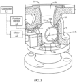
- valve checker system including at least one industrial ball valve 10 and an accompanying operatively connected controller 13 configured to check, validate and maintain the operability of the valve 10, in accordance with a first embodiment of the present disclosure.
- the valve 10 is suitable for use as pumper fire valve of a fire truck (not shown).
- a generic floating industrial ball valve 10 is shown in Figs. 1 and 2 .
- the ball valve 10 includes a valve housing 9, having an inlet 9a and an outlet 9b.
- the valve housing 9 houses a bored out, or otherwise hollow, and rotating/pivoting ball 16 therein.
- a valve seat 18, i.e., an annular seat ring, underlies the ball 16 on an inlet side 20 thereof and an opposing valve seat 18 is positioned upon the ball 16 on an outlet side 22 thereof.
- the rotatable ball 16 defines a port or channel 14 therethrough (or may be otherwise hollow).
- the valve seats 18 on each of the upstream/inlet 20 and downstream/outlet 22 sides of the ball 16 are effectively stationary with respect to the valve housing 9.
- valve seats 18 may be formed of metal(s), polymer(s), combinations thereof, or the like. As also should be understood, the valve seats 18 are configured to seal off and substantially prevent fluid from flowing around the ball 16 between an upstream side 20 and a downstream side 22 thereof, thereby limiting fluid to travel through the ball port 14 in order to travel between the upstream side 20 and the downstream side 22 thereof.
- the ball 16 is rotatable between an open position thereof (not shown) and a fully closed position, i.e., a first closed position, thereof ( Fig. 1 ) in a manner well understood by those of ordinary skill in the art.
- the ball port 14 In the open position, the ball port 14 is in fluid communication with both the upstream inlet 9a and the downstream outlet 9b, such that fluid may flow between the upstream and downstream inlets and outlets 9a, 9b through the ball 16. In the first closed position, the ball port 14 is fluidly disconnected from the upstream and downstream inlet and outlet 9a, 9b.
- the valve 10 may be electrically power actuated.
- the valve may be air power operated, e.g., by using a three-position air cylinder that allows the valve 10 to move as needed, e.g., a small amount for valve checking (as described in further detail below) or the full operational valve movement.
- the controller 13 is employed to power the necessary components in a manner well understood by those of ordinary skill in the art and further described below.
- the valve 10 may also be manually operated, e.g., by adding a short stroke air actuator (not shown) that can move the valve 10 through the small rotation needed to check the valve operation and prevent sticking (as described below).
- actuation may be built into the valve 10 or the manual actuator and incorporates a lost motion mechanical linkage to allow full travel of the valve to be operated manually through the full range of motion.
- valves employed in fire trucks have mechanical clearances between the interrelated components that form the valve. That is, for example, the valve 10 may be designed so that the ball 16 can move a certain/discrete angle of rotation relative to the valve seat(s) 18, i.e., to a second closed position ( Fig. 3 ), with the valve 10 remaining closed, i.e., with the seal remaining intact before the seal is un-ported and fluid begins to flow.
- valve element e.g., the ball 16 (or disc as described below)
- a discrete angular amount from the first closed position to the second closed position
- the ball valve 10 has a measurable displacement 12 between the ball port 14 and an inner peripheral edge18b of each valve seat 18 within the valve housing 9. That is, the ball 16 can move a discrete angle of rotation (from the first closed position to the second closed position) while remaining closed, i.e., before the port (or hole) 14 in the ball 16 breaches the inner peripheral edge 18b of the valve seat 18 and permits flow between the inlet 9a and the outlet 9b of the valve housing 9, through the ball port 14.
- the displacement 12 translates to the permissible angle of rotation of the ball 16 about a rotational axis A, while maintaining the seal between the ball 16 and the valve seat 18, before flow may begin.
- the angle of rotation between the first and second closed positions may be different for different types or designs of valves.
- the valve 10 can be designed to permit more or less movement of the ball 16 while remaining closed, before the seal is un-ported and flow begins.
- a Model 8825, two-and-a-half-inch Generation II Heavy Duty "Self Locking" Swing-Out Ball Valve sold by Akron ® Brass Company (the Model 8825 valve) is designed to permit the rotatable ball of the valve to rotate nine degrees before the valve opens and allows fluid flow through the valve. That is, the valve remains closed until the ball is rotated past nine degrees.
- the controller 13 operatively connected with the valve 10 may actuate, e.g., electrically, the valve 10 to move a predetermined amount between the open and closed positions thereof.
- the controller 13 may act on the ball 16 by activating a motor 11, e.g., a DC motor, coupled to the ball 16 for effecting rotation thereof about the rotational axis A.
- the controller 13 may take the form of a SAM TM Control System sold by Hale Products Inc. integrated into the fire pump, which is configured to manage a fire truck's pump, tank, intakes and discharges.
- the controller 13 may take the form of a Class 1 Sentry Pressure Governor System sold by Hale Products Inc. or a Total Pressure Governor (TPG) sold by Hale Products Inc.
- the controller 13 may periodically, e.g., during times when the pump(s) (not shown) is not engaged and is not pressurized, actuate the valve 10 between the first ( Fig. 1 ) and second ( Fig. 3 ) closed positions thereof, i.e., move the ball 16, a discrete, incremental amount less than the measurable displacement 12 between the ball port 14 and the interior periphery 18b of each valve seat 18, to take up the clearance in the valve 10.
- the pump(s) is not pressurized when not connected with a water source, such as when the truck is sitting idle or driving down the road. Accordingly, residual pressure behind the valve(s) is minor head pressure of any residual water that might be in the pump(s).
- the valve 10 may also be configured to have position feedback.
- a position sensor 15 may be employed in a conventional manner to detect change in position of the ball 16 (the movable valve element) and transmit the information to the controller 13 (in a manner well understood by those of ordinary skill in the art).
- the controller 13 may determine whether, and how much, the ball 16 has moved.
- the controller 13 may be configured to move the ball 16 a certain amount based on the feedback provided by the position sensor 15. For example, in the Akron Brass Co. Model 8825 valve, the controller 13 may be configured to move the ball 16 less than 9 degrees, e.g., 5-6 degrees, toward the open position (which will still prevent fluid from flowing through the valve 10) and then move the ball 16 back to the fully closed position.
- valve 10 may employ a limit switch, as described further below.
- the control system to check and/or actuate the valves can be deployed to a networked arrangement of valves (not shown) to command the valves to operate through the valve checker routine or can be applied to the valves individually as part of a standalone valve routine.
- the controller 13 may cycle through the valves 10 in series in the valve-check mode, so that the electrical load on the electrical system of the vehicle/apparatus does not encounter an excessive load. Different valves have different dwell times that determine how long they can be unactuated before they begin to stick. Accordingly, the controller 13 may be configured to conduct the valve-check on the valves periodically according to the particular valves employed and before stiction occurs.
- one valve-check per valve per day is an average frequency, but the disclosure is not so limited. For example, smaller valves with more rigid seats can last longer times between being moved. Different valves also may require a different amount of valve movement to prevent sticking. Accordingly, the controller 13 may also be configured to move the valve(s) a discrete amount, respectively, corresponding to the design of the particular valve(s).
- the combination of powered operation/actuation of a valve i.e., via the controller 13, and position sensing feedback, enables detection of valve malfunction prior to actual, necessary use. That is, for example, if the controller 13 commands the motor 11 to move the ball 16 and the position sensor 15 detects that the ball 16 does not move, the feedback of the position sensor 15 to the controller 13 will indicate a malfunction, e.g., electrical or mechanical, because the expected position change from the valve 10 was not obtained. Accordingly, defects, such as, for example, without limitation, a broken motor or a number of other mechanical failures or malfunctioning electronics can be detected.
- such action on each valve 10 can be accomplished while the pumper truck/vehicle is sitting idle or on the road, without impacting other activity.
- electronics hardware may additionally or alternatively be employed to detect valve actuation motor current, thereby providing electrical feedback.
- electric actuator Model No. 8615-8635 sold by Akron ® Brass Company
- a valve actuator/controller that measures current draw of the motor as part of the controller design in order to set valve stop positions (as known to those skilled in the art)
- Excessive motor current detection indicates valve malfunction and may be reported (as described above). For example, if the maximum motor current for a valve 10 is approximately 10 amps, the current draw to actuate the valve 10 without pressure on the valve, i.e., when not connected with a water source (as the valve 10 would be when checked), is much less at 4 amps.
- the electronics hardware detects that valve actuation is requiring more than 4 amps at nominal voltage, a malfunction is identified by the controller 13. Whether the issue is mechanical malfunction or electrical, the problem may be reported to avoid malfunction during an emergency situation.
- the controller 13 may also be configured to adjust for current draw and position feedback to learn or self-calibrate how much current each valve needs to move to its checking position, and then when a valve needs more current it can identify a deteriorating problem over time. By measuring the voltage in the power supply and the current required to move the valve a map of known good ranges can be developed so when a valve needs more current to move over a number of automatic checks, a future need for maintenance can be extrapolated.
- employing the position sensor 15 assists with malfunction detection. For example, if power is supplied to the motor 11 and the position sensor 15 detects no position change of the valve 10, then there is a functional, i.e., mechanical or electrical, problem. Further advantageously, combining the position feedback with the electrical feedback may assist in also identifying the type of functional malfunction present. For example, if power is applied to the motor 11 and the electronics hardware detects substantially zero current draw and no position change of the valve 10, then the malfunction is likely an electrical malfunction. Alternatively, if power is applied to the motor 11 and the electronics hardware detects high current draw but there is no position change of the valve, then the malfunction is likely a mechanical malfunction.
- valve checker system of the present disclosure provides multiple advantages. That is, the system operates valves, e.g., powered valves or manually actuated valves having a small motion actuator, a discrete amount that exercises each valve to help make sure it is not stuck but rather is fully operational when needed.
- the system is configured to move the valve(s) without opening the valve(s), i.e., without moving the valve to a position which permits any upstream water to flow therethrough. This is achieved by making sure a downstream pump is not spinning and that there is no pressure on the pump and also by moving the valve element only a small amount.
- the system is configured to automatically operate each valve on a regular, periodic basis when the pump is not being used.
- Such configuration includes exercising different size and type valves on different schedules to prevent sticking, as well as moving each valve a tailored, potentially different amount from other valves, to meet the requirements of each particular valve design. Accordingly, the system may be applied, i.e., customized, to individual valves or applied to a networked arrangement of valve.
- Figs. 4 and 5 illustrate a second embodiment of the valve checker system of the present disclosure.
- the reference numerals of the present embodiment are distinguishable from those of the above-described embodiment by a factor of one-hundred (100), but otherwise indicate the same elements as indicated above, except as otherwise specified.
- the description of certain similarities between the embodiments may be omitted herein for the sake of brevity and convenience, and, therefore, is not limiting.
- the valve 110 takes the form of a butterfly valve, such as, for example, without limitation, a Master Intake Valve sold by Hale Products Inc. That is, and as should be understood by those of ordinary skill in the art, the valve 110 includes a valve housing 109 and a butterfly valve disc 116.
- valve is sufficiently broad to cover any valve having a generally disc-shaped closure that is selectively pivotable, i.e., irrespective of pressure differential across the disc-shaped closure, about an axis along a cross-section of a pipe, i.e., perpendicular to the direction of fluid flow, between a fully closed position ( Fig. 4 ) and an open position (as should be understood by those of ordinary skill in the art), to regulate fluid flow.
- valve seal 118 is formed as a component of the movable valve element rather than being a stationary component of, or mounted to, the valve housing 109.
- the radial periphery of the valve disc 116 forms a valve seal 118.
- the disc 116 may be coated with a sealant, e.g., a polymeric coating, such as, but not limited to, nitrile rubber, to enhance the sealing properties of the disc 116.
- the disc 116 takes the form of a double flanged disc, having upper end and lower end peripheral flanges forming the valve seals 118, but the disclosure is not so limited.
- the movable element i.e., the disc 116 of the valve 110 can move a small, incremental angle of rotation (between the first and second closed positions thereof) while the valve remains closed and, therefore, before the seal between the disc 116 and the valve housing 109 is broken and permits flow between the inlet side 120 and the outlet side 122 of the valve housing 109. That is, in the illustrated embodiment, the disc 116 requires sufficient rotation to break both top and bottom seals 118 before the valve 110 opens.
- the controller 113 operatively connected with the valve 110 to actuate the valve 110 between the open and closed positions thereof may periodically, e.g., at times when the pump is not engaged and is not pressurized, actuate the valve 110 between the first and second closed positions thereof, i.e., rotate the disc 116, a discrete angle less than the angle required to open the valve, i.e., break the seal(s) between the disc 116 and the valve body 109 to avoid and/or break stiction.
- the valve 110 may also employ at least one limit switch 117 operatively connected with the valve 110 and the controller 113 (in a manner well understood by those of ordinary skill in the art).
- the limit switch 117 e.g., on the valve actuator/stem, indicates when the valve 110 is fully closed, i.e., in the first closed position.
- the limit switch 117 changes state (in a manner well understood) according to the make-or-break dimensions of the electrical connection thereof.
- the limit switch 117 may be configured such that the electrical connection is broken when the disc 116 reaches the second, closed position thereof. Accordingly, the controller 113 may cut power to the motor 111 upon breaking of the limit switch 117, thereby ceasing disc 116 rotation.
- the limit switch 117 may be configured to change state (from make to break) when the disc 116 rotates between about 4 degrees and about 7 degrees from the fully closed position, which is sufficient rotation to break stiction between the disc 116 and the valve body 109 and verify that the valve actuation components are properly functioning. The motor 111, therefore, stops further rotation, and then the disc 110 can be returned to the fully (first) closed position in the reverse manner.
- the limit switch 117 may be configured such that the electrical connection is broken prior to the disc 116 reaching the second, closed position thereof, i.e., the valve actuating components and the movable valve components are designed such that insufficient movement is attained when the limit switch changes state.
- the controller 113 may be configured to continue powering the motor 111 for a predetermined, short period of time, e.g., between about one second and about two seconds, after breaking the limit switch 117 to allow the disc 116 to rotate between the about 4 degrees and about 7 degrees from the fully closed position.
- a predetermined, short period of time e.g., between about one second and about two seconds
- One factor affecting the predetermined period of time may be, for example, supply voltage to the motor 111.
- the motor 111 turns more slowly and the number of rotations per second are reduced relative to higher supply voltage. To compensate, the timing of the power to the motor 111 is increased proportionally.
- the combination of powered operation/actuation of a valve i.e., via the controller 113, and the limit switch 117, enables detection of valve malfunction prior to actual, necessary use. For example, if the controller 113 commands the motor 111 to move the disc 116 and the limit switch 117 does not change states, the feedback of the limit switch 117 to the controller 113 will indicate a malfunction, e.g., electrical or mechanical, because the expected change of state of the limit switch 117 was not obtained.
- the valve 110 may employ a position sensor 15 as previously described.
Landscapes
- Engineering & Computer Science (AREA)
- General Engineering & Computer Science (AREA)
- Mechanical Engineering (AREA)
- Health & Medical Sciences (AREA)
- Public Health (AREA)
- Business, Economics & Management (AREA)
- Emergency Management (AREA)
- Indication Of The Valve Opening Or Closing Status (AREA)
- Taps Or Cocks (AREA)
- Fire-Extinguishing By Fire Departments, And Fire-Extinguishing Equipment And Control Thereof (AREA)
- Lift Valve (AREA)
Applications Claiming Priority (3)
| Application Number | Priority Date | Filing Date | Title |
|---|---|---|---|
| US202063041448P | 2020-06-19 | 2020-06-19 | |
| PCT/US2020/057678 WO2021086923A1 (en) | 2019-10-28 | 2020-10-28 | Systems and methods for use in operation of a firefighting vehicle |
| PCT/US2021/037905 WO2021257882A1 (en) | 2020-06-19 | 2021-06-17 | Fire truck valve checker system and method |
Publications (3)
| Publication Number | Publication Date |
|---|---|
| EP4168696A1 EP4168696A1 (en) | 2023-04-26 |
| EP4168696B1 true EP4168696B1 (en) | 2025-05-28 |
| EP4168696C0 EP4168696C0 (en) | 2025-05-28 |
Family
ID=79022829
Family Applications (1)
| Application Number | Title | Priority Date | Filing Date |
|---|---|---|---|
| EP21745487.5A Active EP4168696B1 (en) | 2020-06-19 | 2021-06-17 | Fire truck valve checker system and method |
Country Status (4)
| Country | Link |
|---|---|
| US (1) | US12138500B2 (https=) |
| EP (1) | EP4168696B1 (https=) |
| JP (1) | JP7670740B2 (https=) |
| WO (1) | WO2021257882A1 (https=) |
Families Citing this family (1)
| Publication number | Priority date | Publication date | Assignee | Title |
|---|---|---|---|---|
| FR3135123A1 (fr) | 2022-04-29 | 2023-11-03 | Sagemcom Energy & Telecom Sas | Surveillance d’une électrovanne |
Citations (2)
| Publication number | Priority date | Publication date | Assignee | Title |
|---|---|---|---|---|
| JPH02150581A (ja) * | 1988-11-29 | 1990-06-08 | Toto Ltd | 自動水栓 |
| EP1229418A2 (en) * | 2001-01-30 | 2002-08-07 | Aqualisa Products Limited | Water mixing valve apparatus |
Family Cites Families (68)
| Publication number | Priority date | Publication date | Assignee | Title |
|---|---|---|---|---|
| US2275500A (en) | 1942-03-10 | Priming system for centkifugal | ||
| US615689A (en) | 1898-12-13 | eastes | ||
| US2275501A (en) | 1939-03-08 | 1942-03-10 | Laval Steam Turbine Co | Priming system for centrifugal pumps |
| US2275502A (en) | 1939-12-06 | 1942-03-10 | Laval Steam Turbine Co | Priming system for centrifugal pumps |
| US2961968A (en) | 1956-02-02 | 1960-11-29 | Waterous Co | Centrifugal pump and priming pump assembly |
| JPS5932148B2 (ja) * | 1974-10-31 | 1984-08-07 | モリタポンプ カブシキガイシヤ | 消防車による消火方法 |
| US4337830A (en) | 1978-05-03 | 1982-07-06 | Hale Fire Pump Company | Pump assembly |
| JPS5911747U (ja) * | 1982-07-14 | 1984-01-25 | 日本ドライケミカル株式会社 | 消防自動車用自動揚水制御装置 |
| US4914371A (en) | 1986-12-09 | 1990-04-03 | Matsushita Electric Industrial Co., Ltd. | Apparatus for controlling AC servo motor |
| DE4009560C2 (de) * | 1990-03-24 | 1995-11-02 | Bayer Ag | Vorrichtung zur Absperrung bzw. Umlenkung heterogener Gemenge |
| US5423192A (en) | 1993-08-18 | 1995-06-13 | General Electric Company | Electronically commutated motor for driving a compressor |
| US5797421A (en) | 1994-01-12 | 1998-08-25 | Schlumberger Industries, Inc. | Dry hydrant siphon assembly |
| US5536147A (en) | 1994-08-26 | 1996-07-16 | Paco Pumps, Inc. | Vacuum priming system for centrifugal pumps |
| JP3396114B2 (ja) | 1995-06-26 | 2003-04-14 | サンデン株式会社 | ブラシレスモータの制御装置 |
| JP3397007B2 (ja) | 1995-06-30 | 2003-04-14 | 松下電器産業株式会社 | ブラシレスモータ |
| DE19781894T1 (de) | 1996-07-26 | 1999-09-02 | Yokota Mfg | Selbstansaugende Kreiselpumpe |
| DK0972332T3 (da) | 1997-02-05 | 2004-07-26 | Fisher & Paykel Appliances Ltd | Styring af börstelös jævnströmsmotor |
| US5847530A (en) | 1997-08-28 | 1998-12-08 | Barber Colman | Systems and methods for torque control of actuator and brushless DC motor therein |
| US5872434A (en) | 1997-08-28 | 1999-02-16 | Barber Colman Company | Systems and methods for actuator power failure response |
| US5838124A (en) | 1997-08-28 | 1998-11-17 | Barber Colman | Systems and methods for braking of actuator and brushless DC motor therein |
| US6170412B1 (en) | 1998-05-01 | 2001-01-09 | Flexi-Coil Ltd. | Hydraulic system having boost pump in parallel with a primary pump and a boost pump drive therefor |
| US6182588B1 (en) | 1998-05-01 | 2001-02-06 | Flexi-Coil Ltd. | Hydraulic system having boost pump in series with a primary pump and a boost pump drive therefor |
| US6239564B1 (en) | 1998-10-06 | 2001-05-29 | H.R. Textron, Inc. | State advance controller commutation loop for brushless D.C. motors |
| GB9901547D0 (en) | 1999-01-26 | 1999-03-17 | H J Godwin Limited | Improvements in or relating to pumps |
| US6682313B1 (en) | 2000-12-04 | 2004-01-27 | Trident Emergency Products, Llc | Compressed air powered pump priming system |
| US6586898B2 (en) | 2001-05-01 | 2003-07-01 | Magnon Engineering, Inc. | Systems and methods of electric motor control |
| EP1413044B1 (de) | 2001-10-10 | 2010-03-17 | ebm-papst St. Georgen GmbH & Co. KG | Verfahren zum betreiben eines elektronisch kommutierten motors, und motor zur durchführung eines solchen verfahrens |
| DE10308859A1 (de) | 2003-02-27 | 2004-09-16 | Melexis Gmbh | Verfahren zur leistungsoptimalen Ansteuerung von BLDC-Motoren |
| US6991041B2 (en) | 2003-02-28 | 2006-01-31 | Hale Products, Inc. | Compressed air foam pumping system |
| KR100702913B1 (ko) | 2003-03-17 | 2007-04-03 | 마쯔시다덴기산교 가부시키가이샤 | 브러시리스 dc 모터의 구동 방법 및 그 장치 |
| US7287963B2 (en) | 2003-09-30 | 2007-10-30 | Dimension One Spas | Fast pump priming |
| WO2005034329A2 (en) | 2003-10-01 | 2005-04-14 | J. L. Behmer Corporation | Phase angle control for synchronous machine control |
| US20050077057A1 (en) | 2003-10-10 | 2005-04-14 | Hale Products, Inc. | Fire truck booster pump |
| US7205738B2 (en) | 2004-03-24 | 2007-04-17 | Lexmark International, Inc. | Method and apparatus for time-based dc motor commutation |
| US20050271518A1 (en) | 2004-06-04 | 2005-12-08 | Smith & Loveless, Inc. | Pumping method and system |
| BRPI0513022A (pt) | 2004-07-07 | 2008-04-22 | Kidde Fire Fighting Inc | sistema de bombas incluindo bombas hospedeiras e satélites |
| US7331769B2 (en) | 2004-08-06 | 2008-02-19 | Smith & Loveless, Inc. | Pumping system |
| US7514894B2 (en) | 2005-08-09 | 2009-04-07 | Nxp B.V. | Driver for a brushless motor and data reading/writing device comprising a brushless motor controlled by such a driver |
| US7573224B2 (en) | 2005-08-26 | 2009-08-11 | Delphi Technologies, Inc. | Electronic commutation method and related apparatus |
| US7609016B2 (en) | 2006-02-23 | 2009-10-27 | Infineon Technologies Ag | Systems and methods for driving a motor |
| US8376719B2 (en) | 2006-05-23 | 2013-02-19 | Pierce Manufacturing Company | Fire pump for firefighting vehicle |
| US7530404B2 (en) | 2006-07-20 | 2009-05-12 | Hme, Inc. | Compressed fluid system and related method |
| US7874373B2 (en) | 2006-10-19 | 2011-01-25 | Oshkosh Corporation | Pump system for a firefighting vehicle |
| US7845914B2 (en) | 2007-02-15 | 2010-12-07 | Deere & Company | Self-priming fast fill sprayer pump system |
| US8789614B2 (en) | 2008-04-21 | 2014-07-29 | Fire Research Corp. | Ultra-high pressure fire-fighting system |
| JP5021571B2 (ja) | 2008-06-13 | 2012-09-12 | 矢崎総業株式会社 | ガス遮断弁ユニット |
| US8237385B2 (en) | 2008-09-15 | 2012-08-07 | Texas Instruments Incorporated | Systems and methods for detecting position for a brushless DC motor |
| US8159171B2 (en) | 2008-11-13 | 2012-04-17 | Padauk Technology Co., Ltd., R.O.C. | Controller and method for adaptively adjusting motor driving current waveforms |
| JP5195444B2 (ja) | 2009-01-14 | 2013-05-08 | パナソニック株式会社 | ブラシレスdcモータの駆動装置並びにこれを用いた冷蔵庫及び空気調和機 |
| CN102282755B (zh) | 2009-01-14 | 2014-08-27 | 松下电器产业株式会社 | 电动机驱动装置 |
| US8075282B2 (en) | 2009-02-27 | 2011-12-13 | Deere & Company | Sprayer pump primed by using venturi |
| US8339077B2 (en) | 2009-10-08 | 2012-12-25 | Microchip Technology Incorporated | Slow speed operation of brushless direct current motors by gating pulse width modulation drive |
| WO2011054074A1 (en) | 2009-11-06 | 2011-05-12 | Bosch Security Systems Bv | Brushless motor speed control system |
| JP5772029B2 (ja) | 2011-02-08 | 2015-09-02 | アイシン精機株式会社 | センサレスブラシレスモータの駆動装置 |
| US9175686B2 (en) | 2011-09-02 | 2015-11-03 | Waterous Company | Priming valve system for pre-priming centrifugal pump intakes |
| CN102611370B (zh) | 2012-03-19 | 2014-09-03 | 矽力杰半导体技术(杭州)有限公司 | 一种永磁同步电机的正弦调制控制方法及其控制电路 |
| EP2836723A1 (en) | 2012-04-11 | 2015-02-18 | Waterous Company | Integrated reciprocating primer drive arrangement |
| US9413276B2 (en) | 2014-09-24 | 2016-08-09 | Process Control Corporation | DC motor control over wide dynamic range |
| AU2016302065B2 (en) * | 2015-08-05 | 2019-03-14 | Flowserve Pte. Ltd. | Axial-seal butterfly valves |
| US10056852B2 (en) | 2016-01-22 | 2018-08-21 | Canarm Ltd. | Controller for EC motor and method thereof |
| US10970147B2 (en) | 2016-05-24 | 2021-04-06 | Mitsubishi Electric Corporation | Electronic control device and operation control method therefor |
| JP6285523B2 (ja) | 2016-10-24 | 2018-02-28 | 株式会社キッツ | バルブ用電動アクチュエータと緊急遮断弁・緊急開放弁並びにバルブ用電動アクチュエータの異常診断方法 |
| US10711440B2 (en) * | 2018-03-12 | 2020-07-14 | Hale Products, Inc. | Automatic fire hydrant water supplying system |
| CA3115709A1 (en) * | 2018-10-12 | 2020-04-16 | Bray International, Inc. | Smart valve with integrated electronics |
| JP7000297B2 (ja) | 2018-10-31 | 2022-01-19 | 株式会社栗本鐵工所 | バタフライ弁 |
| US10632489B1 (en) * | 2018-11-08 | 2020-04-28 | Cheng-Yu Wang | Sticking elimination method for and structure of the water control valve of a water spraying timer |
| CN109296546A (zh) | 2018-11-19 | 2019-02-01 | 安徽阿莫斯流体技术有限公司 | 一种惰性真空辅助自吸泵 |
| CN110743120A (zh) | 2019-11-18 | 2020-02-04 | 安徽阿莫斯流体技术有限公司 | 一种集成式模块化多功能并具备自吸能力的应急消防车 |
-
2021
- 2021-06-17 EP EP21745487.5A patent/EP4168696B1/en active Active
- 2021-06-17 JP JP2022578673A patent/JP7670740B2/ja active Active
- 2021-06-17 WO PCT/US2021/037905 patent/WO2021257882A1/en not_active Ceased
- 2021-06-17 US US17/350,595 patent/US12138500B2/en active Active
Patent Citations (2)
| Publication number | Priority date | Publication date | Assignee | Title |
|---|---|---|---|---|
| JPH02150581A (ja) * | 1988-11-29 | 1990-06-08 | Toto Ltd | 自動水栓 |
| EP1229418A2 (en) * | 2001-01-30 | 2002-08-07 | Aqualisa Products Limited | Water mixing valve apparatus |
Also Published As
| Publication number | Publication date |
|---|---|
| EP4168696A1 (en) | 2023-04-26 |
| WO2021257882A1 (en) | 2021-12-23 |
| EP4168696C0 (en) | 2025-05-28 |
| JP2023537191A (ja) | 2023-08-31 |
| US12138500B2 (en) | 2024-11-12 |
| US20210394002A1 (en) | 2021-12-23 |
| JP7670740B2 (ja) | 2025-04-30 |
Similar Documents
| Publication | Publication Date | Title |
|---|---|---|
| US6343615B1 (en) | Butterfly valve | |
| EP4168696B1 (en) | Fire truck valve checker system and method | |
| RU2558487C2 (ru) | Устройство для увеличения усиления привода с блокирующим устройством | |
| JP5745591B2 (ja) | 閉塞及び放出バルブアセンブリ | |
| CN114838158B (zh) | 一种球阀阀座密封的自动切换方法 | |
| CN101784827A (zh) | 动力阀的故障检测装置和方法 | |
| US20050279955A1 (en) | Valve, actuator and control system therefor | |
| EP3864330B1 (en) | Slam-shut safety assembly for providing redundant safety shutoff | |
| CA3151291A1 (en) | Ball valve assembly | |
| CN114635980A (zh) | 一种具有自动补偿密封功能的三偏心蝶阀 | |
| CN117515206A (zh) | 一种化工管道用密封面自动检测式球阀 | |
| JP5112088B2 (ja) | 減速機付油圧駆動装置の検査兼用潤滑油供給装置 | |
| WO2013126099A1 (en) | Air valve and method for refurbishing an air valve | |
| CN114593105A (zh) | 一种活塞缸及其控制方法、换挡系统及摘挡控制方法 | |
| US20230286476A1 (en) | Monitoring of landing gear servo valve assembly | |
| KR100408800B1 (ko) | 유체 밀폐성이 우수한 게이트 밸브 | |
| JP2023537191A5 (https=) | ||
| US5540413A (en) | Aircraft pressure-fueling nozzle | |
| US20050284525A1 (en) | Manually-operated piloted control-reliable lockout valve | |
| EP4484660A1 (en) | Flush valve | |
| EP1948984A2 (en) | Valve, actuator and control system therefor | |
| CN217056361U (zh) | 一种电动蝶阀 | |
| CN118346140B (zh) | 一种智能化车库门控系统 | |
| CN219866364U (zh) | 一种复合密封阀 | |
| EP4242077B1 (en) | Monitoring of landing gear servo valve assembly |
Legal Events
| Date | Code | Title | Description |
|---|---|---|---|
| STAA | Information on the status of an ep patent application or granted ep patent |
Free format text: STATUS: UNKNOWN |
|
| STAA | Information on the status of an ep patent application or granted ep patent |
Free format text: STATUS: THE INTERNATIONAL PUBLICATION HAS BEEN MADE |
|
| PUAI | Public reference made under article 153(3) epc to a published international application that has entered the european phase |
Free format text: ORIGINAL CODE: 0009012 |
|
| STAA | Information on the status of an ep patent application or granted ep patent |
Free format text: STATUS: REQUEST FOR EXAMINATION WAS MADE |
|
| 17P | Request for examination filed |
Effective date: 20221227 |
|
| AK | Designated contracting states |
Kind code of ref document: A1 Designated state(s): AL AT BE BG CH CY CZ DE DK EE ES FI FR GB GR HR HU IE IS IT LI LT LU LV MC MK MT NL NO PL PT RO RS SE SI SK SM TR |
|
| DAV | Request for validation of the european patent (deleted) | ||
| DAX | Request for extension of the european patent (deleted) | ||
| GRAP | Despatch of communication of intention to grant a patent |
Free format text: ORIGINAL CODE: EPIDOSNIGR1 |
|
| STAA | Information on the status of an ep patent application or granted ep patent |
Free format text: STATUS: GRANT OF PATENT IS INTENDED |
|
| INTG | Intention to grant announced |
Effective date: 20241218 |
|
| GRAS | Grant fee paid |
Free format text: ORIGINAL CODE: EPIDOSNIGR3 |
|
| GRAA | (expected) grant |
Free format text: ORIGINAL CODE: 0009210 |
|
| STAA | Information on the status of an ep patent application or granted ep patent |
Free format text: STATUS: THE PATENT HAS BEEN GRANTED |
|
| AK | Designated contracting states |
Kind code of ref document: B1 Designated state(s): AL AT BE BG CH CY CZ DE DK EE ES FI FR GB GR HR HU IE IS IT LI LT LU LV MC MK MT NL NO PL PT RO RS SE SI SK SM TR |
|
| REG | Reference to a national code |
Ref country code: GB Ref legal event code: FG4D |
|
| REG | Reference to a national code |
Ref country code: CH Ref legal event code: EP |
|
| REG | Reference to a national code |
Ref country code: IE Ref legal event code: FG4D Ref country code: DE Ref legal event code: R096 Ref document number: 602021031448 Country of ref document: DE |
|
| PGFP | Annual fee paid to national office [announced via postgrant information from national office to epo] |
Ref country code: GB Payment date: 20250618 Year of fee payment: 5 |
|
| PGFP | Annual fee paid to national office [announced via postgrant information from national office to epo] |
Ref country code: AT Payment date: 20250721 Year of fee payment: 5 |
|
| U01 | Request for unitary effect filed |
Effective date: 20250623 |
|
| U07 | Unitary effect registered |
Designated state(s): AT BE BG DE DK EE FI FR IT LT LU LV MT NL PT RO SE SI Effective date: 20250701 |
|
| U20 | Renewal fee for the european patent with unitary effect paid |
Year of fee payment: 5 Effective date: 20250728 |
|
| PG25 | Lapsed in a contracting state [announced via postgrant information from national office to epo] |
Ref country code: ES Free format text: LAPSE BECAUSE OF FAILURE TO SUBMIT A TRANSLATION OF THE DESCRIPTION OR TO PAY THE FEE WITHIN THE PRESCRIBED TIME-LIMIT Effective date: 20250528 |
|
| PG25 | Lapsed in a contracting state [announced via postgrant information from national office to epo] |
Ref country code: NO Free format text: LAPSE BECAUSE OF FAILURE TO SUBMIT A TRANSLATION OF THE DESCRIPTION OR TO PAY THE FEE WITHIN THE PRESCRIBED TIME-LIMIT Effective date: 20250828 Ref country code: GR Free format text: LAPSE BECAUSE OF FAILURE TO SUBMIT A TRANSLATION OF THE DESCRIPTION OR TO PAY THE FEE WITHIN THE PRESCRIBED TIME-LIMIT Effective date: 20250829 |
|
| PG25 | Lapsed in a contracting state [announced via postgrant information from national office to epo] |
Ref country code: PL Free format text: LAPSE BECAUSE OF FAILURE TO SUBMIT A TRANSLATION OF THE DESCRIPTION OR TO PAY THE FEE WITHIN THE PRESCRIBED TIME-LIMIT Effective date: 20250528 |
|
| PG25 | Lapsed in a contracting state [announced via postgrant information from national office to epo] |
Ref country code: HR Free format text: LAPSE BECAUSE OF FAILURE TO SUBMIT A TRANSLATION OF THE DESCRIPTION OR TO PAY THE FEE WITHIN THE PRESCRIBED TIME-LIMIT Effective date: 20250528 |
|
| PG25 | Lapsed in a contracting state [announced via postgrant information from national office to epo] |
Ref country code: RS Free format text: LAPSE BECAUSE OF FAILURE TO SUBMIT A TRANSLATION OF THE DESCRIPTION OR TO PAY THE FEE WITHIN THE PRESCRIBED TIME-LIMIT Effective date: 20250828 |
|
| PG25 | Lapsed in a contracting state [announced via postgrant information from national office to epo] |
Ref country code: IS Free format text: LAPSE BECAUSE OF FAILURE TO SUBMIT A TRANSLATION OF THE DESCRIPTION OR TO PAY THE FEE WITHIN THE PRESCRIBED TIME-LIMIT Effective date: 20250928 |
|
| PG25 | Lapsed in a contracting state [announced via postgrant information from national office to epo] |
Ref country code: SM Free format text: LAPSE BECAUSE OF FAILURE TO SUBMIT A TRANSLATION OF THE DESCRIPTION OR TO PAY THE FEE WITHIN THE PRESCRIBED TIME-LIMIT Effective date: 20250528 |
|
| PG25 | Lapsed in a contracting state [announced via postgrant information from national office to epo] |
Ref country code: CZ Free format text: LAPSE BECAUSE OF FAILURE TO SUBMIT A TRANSLATION OF THE DESCRIPTION OR TO PAY THE FEE WITHIN THE PRESCRIBED TIME-LIMIT Effective date: 20250528 |
|
| PG25 | Lapsed in a contracting state [announced via postgrant information from national office to epo] |
Ref country code: SK Free format text: LAPSE BECAUSE OF FAILURE TO SUBMIT A TRANSLATION OF THE DESCRIPTION OR TO PAY THE FEE WITHIN THE PRESCRIBED TIME-LIMIT Effective date: 20250528 |
|
| REG | Reference to a national code |
Ref country code: CH Ref legal event code: H13 Free format text: ST27 STATUS EVENT CODE: U-0-0-H10-H13 (AS PROVIDED BY THE NATIONAL OFFICE) Effective date: 20260127 |
|
| PG25 | Lapsed in a contracting state [announced via postgrant information from national office to epo] |
Ref country code: MC Free format text: LAPSE BECAUSE OF FAILURE TO SUBMIT A TRANSLATION OF THE DESCRIPTION OR TO PAY THE FEE WITHIN THE PRESCRIBED TIME-LIMIT Effective date: 20250528 |
|
| PLBE | No opposition filed within time limit |
Free format text: ORIGINAL CODE: 0009261 |
|
| STAA | Information on the status of an ep patent application or granted ep patent |
Free format text: STATUS: NO OPPOSITION FILED WITHIN TIME LIMIT |
|
| REG | Reference to a national code |
Ref country code: CH Ref legal event code: L10 Free format text: ST27 STATUS EVENT CODE: U-0-0-L10-L00 (AS PROVIDED BY THE NATIONAL OFFICE) Effective date: 20260409 |
|
| PG25 | Lapsed in a contracting state [announced via postgrant information from national office to epo] |
Ref country code: IE Free format text: LAPSE BECAUSE OF NON-PAYMENT OF DUE FEES Effective date: 20250617 |
|
| PG25 | Lapsed in a contracting state [announced via postgrant information from national office to epo] |
Ref country code: CH Free format text: LAPSE BECAUSE OF NON-PAYMENT OF DUE FEES Effective date: 20250630 |