EP4168651B1 - Vorrichtung und verfahren zum vortreiben eines tunnels - Google Patents
Vorrichtung und verfahren zum vortreiben eines tunnels Download PDFInfo
- Publication number
- EP4168651B1 EP4168651B1 EP21835196.3A EP21835196A EP4168651B1 EP 4168651 B1 EP4168651 B1 EP 4168651B1 EP 21835196 A EP21835196 A EP 21835196A EP 4168651 B1 EP4168651 B1 EP 4168651B1
- Authority
- EP
- European Patent Office
- Prior art keywords
- cutting wheel
- measured values
- face
- tunnel
- front face
- Prior art date
- Legal status (The legal status is an assumption and is not a legal conclusion. Google has not performed a legal analysis and makes no representation as to the accuracy of the status listed.)
- Active
Links
Images




Classifications
-
- E—FIXED CONSTRUCTIONS
- E21—EARTH OR ROCK DRILLING; MINING
- E21D—SHAFTS; TUNNELS; GALLERIES; LARGE UNDERGROUND CHAMBERS
- E21D9/00—Tunnels or galleries, with or without linings; Methods or apparatus for making thereof; Layout of tunnels or galleries
- E21D9/003—Arrangement of measuring or indicating devices for use during driving of tunnels, e.g. for guiding machines
-
- E—FIXED CONSTRUCTIONS
- E21—EARTH OR ROCK DRILLING; MINING
- E21B—EARTH OR ROCK DRILLING; OBTAINING OIL, GAS, WATER, SOLUBLE OR MELTABLE MATERIALS OR A SLURRY OF MINERALS FROM WELLS
- E21B49/00—Testing the nature of borehole walls; Formation testing; Methods or apparatus for obtaining samples of soil or well fluids, specially adapted to earth drilling or wells
- E21B49/005—Testing the nature of borehole walls or the formation by using drilling mud or cutting data
-
- E—FIXED CONSTRUCTIONS
- E21—EARTH OR ROCK DRILLING; MINING
- E21C—MINING OR QUARRYING
- E21C39/00—Devices for testing in situ the hardness or other properties of minerals, e.g. for giving information as to the selection of suitable mining tools
-
- E—FIXED CONSTRUCTIONS
- E21—EARTH OR ROCK DRILLING; MINING
- E21D—SHAFTS; TUNNELS; GALLERIES; LARGE UNDERGROUND CHAMBERS
- E21D9/00—Tunnels or galleries, with or without linings; Methods or apparatus for making thereof; Layout of tunnels or galleries
- E21D9/06—Making by using a driving shield, i.e. advanced by pushing means bearing against the already placed lining
-
- E—FIXED CONSTRUCTIONS
- E21—EARTH OR ROCK DRILLING; MINING
- E21D—SHAFTS; TUNNELS; GALLERIES; LARGE UNDERGROUND CHAMBERS
- E21D9/00—Tunnels or galleries, with or without linings; Methods or apparatus for making thereof; Layout of tunnels or galleries
- E21D9/06—Making by using a driving shield, i.e. advanced by pushing means bearing against the already placed lining
- E21D9/0642—Making by using a driving shield, i.e. advanced by pushing means bearing against the already placed lining the shield having means for additional processing at the front end
- E21D9/0678—Adding additives, e.g. chemical compositions, to the slurry or the cuttings
-
- E—FIXED CONSTRUCTIONS
- E21—EARTH OR ROCK DRILLING; MINING
- E21D—SHAFTS; TUNNELS; GALLERIES; LARGE UNDERGROUND CHAMBERS
- E21D9/00—Tunnels or galleries, with or without linings; Methods or apparatus for making thereof; Layout of tunnels or galleries
- E21D9/10—Making by using boring or cutting machines
- E21D9/11—Making by using boring or cutting machines with a rotary drilling-head cutting simultaneously the whole cross-section, i.e. full-face machines
- E21D9/112—Making by using boring or cutting machines with a rotary drilling-head cutting simultaneously the whole cross-section, i.e. full-face machines by means of one single rotary head or of concentric rotary heads
-
- E—FIXED CONSTRUCTIONS
- E21—EARTH OR ROCK DRILLING; MINING
- E21D—SHAFTS; TUNNELS; GALLERIES; LARGE UNDERGROUND CHAMBERS
- E21D9/00—Tunnels or galleries, with or without linings; Methods or apparatus for making thereof; Layout of tunnels or galleries
- E21D9/12—Devices for removing or hauling away excavated material or spoil; Working or loading platforms
Definitions
- the invention relates to a device for driving a tunnel according to the preamble of claim 1.
- the invention further relates to a method for driving a tunnel.
- Such a device is out US 5,106,163 A known.
- the previously known device has a rotatable cutting wheel with which geology can be mined in a forward direction on the front side of a face with mining tools arranged on the front side of the cutting wheel. Material mined from the face can be conveyed into a mining chamber located on the back of the front of the cutting wheel.
- sensor means are provided which are arranged on the front of the cutting wheel and which are set up for optically examining the condition of mining tools or their surrounding area in the direction of advance in front of the front of the cutting wheel.
- a tunnel can be driven using the previously known device.
- JP 2015 212476 A is a method for recording the properties of mined material in a tunnel boring machine Mining chamber and a device for testing the plastic fluidity of earth and sand are known, in which additives introduced into a chamber on the back of a cutting wheel can be mixed with the mined material by means of mutually movable mixing organs and the resulting mixture can be tested for certain fluidity properties.
- HERRENKNECHT MARTIN ET AL "The development of earth pressure shields: from the beginning to the present / Development of earth pressure shields: From the beginning to the present"
- GEOMECHANICS AND TUNNELING GEOMECHANICS AND TUNNELING, Vol. 4, No. 1, 1. February 2011 (2011-02-01), pages 11-35, XP055902975,DE ISSN: 1865-7362, DOI: 10.1002/geot.201100003
- a tunnel boring machine is known that is set up to optically monitor mined soil material in a mining chamber with a camera.
- JP 2016 003 430 A a tunnel boring machine is known which is aligned with acceleration sensors in order to obtain measured values for a distribution of soil at predetermined rotation angles.
- a tunnel boring machine which is designed to obtain information about the soil in the area of the front of the cutting wheel by means of sound sensors arranged on the front of the cutting wheel.
- a tunnel boring machine which is set up to obtain information about the face using a three-dimensional image acquisition device.
- JP H02 43493 A tunnel boring machine is known in which the condition of mined material introduced into a mining chamber arranged on the back of a cutting wheel can be detected via the discharge path by means of pressure sensors in order to ensure reliable conveyance of the mined material.
- a device which has a rotatable cutting wheel with which geology present on the front side of a face in a forward direction can be mined with mining tools arranged on the front side of the cutting wheel. Material mined from the face can be conveyed into a mining chamber located on the back of the front of the cutting wheel in the mining direction. There is also a removal unit with which material present in the excavation chamber can be removed. Furthermore, sensor means are provided which interact with the material present in the excavation chamber to record measured values characteristic of the consistency of material mined at the face. A tunnel can be driven using the previously known device.
- a position determination system for a drive-on machine which has conductor loops and at least one magnetic field detector, which can be moved relative to one another in order to calculate the position of the drive-on machine relative to a reference position using a position computer.
- a device for examining the sticking of sample material to predict mining conditions in tunneling which is integrated in a test stand and has a rotatable cutting wheel arranged in a material receiving tube.
- the cutting wheel is intended to come into contact with sample material introduced into the material receiving tube and is equipped for this purpose with sensors which are set up to measure at least one measurement variable.
- the measured variables include cutting wheel deformation, cutting wheel torque, electrical conductivity on the cutting wheel, wear on the cutting wheel and pressure on the cutting wheel.
- the invention is based on the object of providing a device of the type mentioned at the outset, with which the consistency of the material present between the front of the cutting wheel and the face can be adjusted, in particular to relatively reliably avoid undesirable sticking and excess Wear and tear as well as for operationally reliable support of the face can be reliably determined.
- measuring modules of the sensor means are arranged on the front of the cutting wheel and the measuring modules arranged there are set up to record different types of measured values that are characteristic of the consistency of material mined at the face
- the consistency of between the front of the cutting wheel and the face of the material present can be determined very directly and relatively precisely by linking the measured values of different types, so that the consistency of this material can be influenced directly, for example via a control loop unit with conditioning agents. This makes it possible to avoid unwanted adhesions and excessive wear on mining tools and to provide reliable support for the face.
- Fig. 1 shows, in a schematic, simplified side view, an exemplary embodiment of a device for driving a tunnel according to the invention in the form of a tunnel boring machine 103 set up for earth pressure-assisted (EPB) tunnel driving.
- the tunnel boring machine 103 has a cutting wheel 109 which can be rotated via a cutting wheel drive unit 106 and has a cutting wheel 112 on the front side of the cutting wheel Number of mining tools 115 are arranged.
- material can be mined on a face 118 located in front of the cutting wheel 109 in the direction of advance.
- Material mined at the face 118 can be conveyed into a mining chamber 121 located on the back of the front side of the cutting wheel 112 in the mining direction.
- the mined material can be conveyed from the mining chamber 121 to a discharge opening 133 via a discharge unit with a discharge screw unit 124, which has a helical screw 130 that can rotate in a cladding tube 127.
- one end of a discharge belt 136 of the discharge unit is arranged, with which the discharged material can be conveyed away through a tunnel space 139.
- the tunnel space 139 is lined with segments 142 on the back of the cutting wheel 109, with advancing presses 145 supporting the cutting wheel drive unit 106 on the end faces of the last installed segments 142 facing the cutting wheel 109 Machine frame 148 and thus the cutting wheel 109 can be pressed against the face 118.
- the tunnel boring machine 103 shown is equipped on the cutting wheel front 112 in addition to the mining tools 115 with at least two measuring modules of sensor means for detecting different types of measured values, which in one embodiment in at least one pairwise combination at least one multi-measuring module 151, at least one spindle measuring module 154, at least one ram measuring module 157, at least one earth pressure measurement module 160 or at least one temperature measurement module 163.
- the measuring modules 151, 154, 157, 160, 163 of the sensor means are, as explained in more detail below, set up to record measured values with a stationary cutting wheel 109 or with a rotating cutting wheel 109, from which characteristic, overall for the consistency of the between the front side of the cutting wheel 112 and the material present on the face 118 are characteristic measurement variables for a control loop unit for the controlled, largely automated conditioning of the material present between the front side of the cutting wheel 112 and the face 118 via in Fig. 1 Conditioning agents added to conditioning organs, not shown, can be adjusted.
- At least some plunger measuring modules 157 are expediently dimensioned so that they can Need for positions of mining tools 115 can be installed.
- the earth pressure acting on the front of the cutting wheel 112 can be determined, which is related to the consistency of the material in question. For example, when there is an opportunity for relaxation such as by draining, flowable material exerts lower pressures and more pasty material exerts higher pressures on the earth pressure measurement module 160, which is reflected in the measured values output by the earth pressure measurement module 160.
- the temperature of the material present between the front of the cutting wheel 112 and the face 118 in the vicinity of the temperature measuring module 163 can be determined, the temperature being related to the consistency of the material.
- a relatively high temperature is characteristic for high friction and thus for a relatively viscous to pasty consistency of the material
- a relatively low temperature is characteristic for a more flowable consistency of the material that generates little frictional heat.
- the measured value output by the temperature measurement module 163 is therefore also characteristic of the consistency of the material.
- Conditioning elements arranged on the face 118 are set up to produce at least two zones of different consistencies by appropriate addition of conditioning agent.
- Each of these zones can be sampled by at least one measuring module 151, 154, 157, 160, 163 in order to obtain measured values characteristic of the respective consistency.
- Fig. 1 can be seen that on the machine frame 148 on its side adjacent to the excavation chamber 121 there are further measuring modules of sensor means, in particular in the form of spindle measuring modules 154, which are each connected to the cladding tube 127 via a bypass line 155, a plunger measuring module 157 arranged approximately in the middle, earth pressure measuring modules 160 and temperature measurement modules 163 are arranged.
- sensor means in particular in the form of spindle measuring modules 154, which are each connected to the cladding tube 127 via a bypass line 155, a plunger measuring module 157 arranged approximately in the middle, earth pressure measuring modules 160 and temperature measurement modules 163 are arranged.
- sensor means different types of measured values characteristic of the consistency of the material present in the excavation chamber 121 can also be recorded, in particular by adding conditioning agent into the excavation chamber 121 by means of Fig. 1 Conditioning elements, not shown, to ensure proper operation of the screw conveyor unit 124.
- the consistencies of the material between the front of the cutting wheel 112 and the face 118 on the one hand, and there, as explained in more detail below, preferably in the radial direction also in zones, and in the excavation chamber 121 on the other hand, are optionally adjustable and If necessary, in particular also noticeably different, for example in order to obtain a relatively solid consistency for the material thrown onto the discharge belt 136.
- the conveyor screw unit 124 is also equipped with at least one sensor means, here in the form of at least one plunger measuring module 157, in order to record measured values characteristic of the consistency of the material conveyed away.
- the tunnel boring machine 103 has a further measuring module of the sensor means Fig. 1 via an image recording module 166, with which images of the material discharged at the discharge opening 133 and removed from the excavation chamber 121 can be recorded.
- the tunnel boring machine 103 is also equipped with an operating data acquisition module 169 and a visualization module 172.
- the operating data acquisition module 169 the different types of measured values recorded by the measuring modules 151, 154, 157, 160, 163 as well as the images of the image recording module 166 can be stored in order to obtain further measured values based on automated image analysis and can be used as input variables for a control loop unit for, if necessary, separately conditioning the material the front of the cutting wheel 112 and the face 118 and can be processed in the excavation chamber 121.
- the visualization module 172 is used for display typical operating parameter for operating personnel to be able to intervene manually to condition the material if necessary.
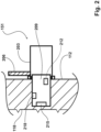
- Fig. 2 shows a schematic side view of a multi-measuring module 151 based on Fig. 1 explained tunnel boring machine 103.
- the multi-measuring module 151 in this embodiment has a stamp receiving pot 203 that is closed at the back and can be closed via a locking slide 206 in the area of the front side of the cutting wheel 112 against the material between the front side of the cutting wheel 112 and the face 118.
- the multi-measuring module 151 is also equipped with a sensor carrier stamp 209, which comes out of the stamp receiving pot 203 when the locking slide 206 is open Fig. 2 Displacement elements, not shown, can be moved.
- the sensor carrier stamp 209 is equipped with at least one bending sensor 212, for example in the form of a strain gauge, with at least one facing the face 118, with at least one earth pressure sensor 215 arranged on the front side and with at least one temperature sensor 218, with which the deformation of the sensor carrier stamp is recorded when the cutting wheel 109 rotates 209, the pressure exerted on the sensor carrier stamp 209 by the material or in the area of the sensor carrier stamp 209 in the material prevailing temperature can be recorded as measured values.
- at least one bending sensor 212 for example in the form of a strain gauge, with at least one facing the face 118, with at least one earth pressure sensor 215 arranged on the front side and with at least one temperature sensor 218, with which the deformation of the sensor carrier stamp is recorded when the cutting wheel 109 rotates 209, the pressure exerted on the sensor carrier stamp 209 by the material or in the area of the sensor carrier stamp 209 in the material prevailing temperature can be recorded as measured values.
- Fig. 3 shows a schematic side view of a spindle measuring module 154 based on Fig. 1 explained tunnel boring machine 103.
- the spindle measuring module 154 has a rotatable sampling screw 303, which is mounted in a guide tube 306 arranged on the back of the front side of the cutting wheel 112 in the direction of advance.
- the guide tube 306 can be closed on its side facing the front of the cutting wheel 112 via an inlet slide 309 against the material on the face 118, while on its side facing away from the front of the cutting wheel 112 a sampling tube 312 is flanged, into which when the sampling screw 303 is rotated after opening the inlet slide 309 material standing on the front of the cutting wheel 112 can be fed in.
- Moisture sensors 315 and a sound transmission unit with a sound generator 318 and a sound sensor 321 are attached to the sampling tube 312. With the moisture sensors 315, the moisture can be determined as a measured value as well as transmission parameters as further measured values that are characteristic of the consistency of the sampled material.
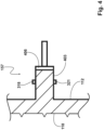
- Fig. 4 shows a schematic side view of a ram measuring module 157 of the tunnel boring machine 103 according to Fig. 1 .
- the plunger measuring module 157 is equipped with a material receiving pot 403, which is open on the front of the cutting wheel 112 and is closed on the back by an ejection plunger 406 that can be displaced in the longitudinal direction of the material receiving pot 403.
- a sound transmission unit with a sound generator 318 and a sound sensor 321 is arranged on the material receiving pot 403, with which measured values characteristic of the consistency of the material present in the material receiving pot 403 can be recorded.
- the ejection plunger 406 can expediently be moved at least flush with the front of the cutting wheel 112 in order to allow new material to enter the material receiving pot 403 after a certain time after being pushed back and then to provide measured values characteristic of its consistency to be recorded again.
- the plunger measuring module 157 is set up to provide distance-force measurement values both when extending and beyond the front of the cutting wheel 112 into the existing material and when retracting, i.e. those for covering a certain distance when extending and / or when Force to be exerted when retracting, which is characteristic of the consistency of the material in question.
- Fig. 5 shows a simplified side view of a moisture measuring module 503 as a further measuring module of the sensor means, which is equipped with a material receiving pot 506 that is open on the front of the cutting wheel 112.
- a number of moisture sensors 315 are arranged on the side walls of the material receiving pot 506, with which the moisture of the material present in the material receiving pot 506 can be determined as measured values.
- the moisture measuring module 503 has a flow meter 512, with which a volume flow of liquid pressed out of the material present in the material receiving pot 506 due to the existing pressure can be recorded as a further measured value characteristic of the consistency of the material.
- Fig. 6 shows a schematic side view of a further development of a helical screw 130 of a screw conveyor unit 124, which is based on Fig. 1
- Guided conveyor screw unit 124 is formed with a helical screw 130 rotatably arranged in a cladding tube 127.
- the spiral screw 130 When executed in accordance with Fig. 6 is the spiral screw 130 with a first spiral section 603 and with a second Helical section 606 is formed, which are arranged at a distance from one another, so that a helical-free space 609 is formed between them.
- At least one moisture sensor 315 and a sound transmission unit with a sound generator 318 and with a sound sensor 321 are arranged, with which the material transported through the cladding tube when the spiral screw 130 rotates can be sampled.
- Fig. 7 shows a front view of a cutting wheel front side 112 of a cutting wheel 109 of a tunnel boring machine 103, shown hatched with main arms 703 and with side arms 706 and with intermediate openings, with a number of measuring modules, here in the form of multi-measuring modules 151, spindle measuring modules 154, ram measuring modules 157, earth pressure measuring modules 160 and temperature measuring module en 163 and if necessary from in Fig. 7 Moisture measuring modules 503, not shown, which are arranged at different distances from a center 709 of the cutting wheel 109 and thus on radially different circumferential paths when the cutting wheel 109 rotates.
- measuring modules here in the form of multi-measuring modules 151, spindle measuring modules 154, ram measuring modules 157, earth pressure measuring modules 160 and temperature measuring module en 163 and if necessary from in Fig. 7
- Moisture measuring modules 503, not shown which are arranged at different distances from a center 709 of the cutting wheel 109
- This arrangement of the measuring modules 151, 154, 157, 160, 163, 503 makes it possible, as already explained above, to sample radially differently located zones separately and to specifically condition the consistencies of the material between the front side of the cutting wheel 112 and the face 118 with appropriately arranged conditioning elements .
- Fig. 8 shows a block diagram of an exemplary embodiment of a control loop for setting consistencies in an area between the front of the cutting wheel 112 and the face 118 with existing geology 803.
- the measuring modules 151, 154, 157, 160, 163, 503 record different types of measured values from the area with existing geology 803 and feed them to the operating data acquisition module 169.
- the images from the image capture module 166 are transferred to the operating data acquisition module 169 for evaluation.
- the operating data acquisition module 169 On the basis of the data fed to the operating data acquisition module 169 and displayed visually via the visualization module 172 in the form of measured values and images, the operating data acquisition module 169 generates output data that can be fed to a conditioning system 806, which includes the aforementioned conditioning elements and conditioning means.
- the initial data are set up in such a way that the consistency or consistencies in the area between the front of the cutting wheel 112 and the face 118 with the existing geology 803 can be optionally adjusted with the conditioning system 806 to obtain the desired consistency or consist
Landscapes
- Engineering & Computer Science (AREA)
- Mining & Mineral Resources (AREA)
- Geology (AREA)
- Life Sciences & Earth Sciences (AREA)
- General Life Sciences & Earth Sciences (AREA)
- Geochemistry & Mineralogy (AREA)
- Environmental & Geological Engineering (AREA)
- Physics & Mathematics (AREA)
- Fluid Mechanics (AREA)
- Chemical & Material Sciences (AREA)
- Chemical Kinetics & Catalysis (AREA)
- General Chemical & Material Sciences (AREA)
- Excavating Of Shafts Or Tunnels (AREA)
- Sampling And Sample Adjustment (AREA)
Description
- Die Erfindung betrifft eine Vorrichtung zum Vortreiben eines Tunnels gemäß dem Oberbegriff des Anspruchs 1.
- Die Erfindung betrifft weiterhin ein Verfahren zum Vortreiben eines Tunnels.
- Eine derartige Vorrichtung ist aus
US 5 106 163 A bekannt. Die vorbekannte Vorrichtung verfügt über ein drehbares Schneidrad, mit dem in einer Vortriebsrichtung vorderseitig an einer Ortsbrust mit an einer Schneidradvorderseite angeordneten Abbauwerkzeugen anstehende Geologie abbaubar ist. Von der Ortsbrust abgebautes Material ist in eine Abbaurichtung rückseitig der Schneidradvorderseite gelegene Abbaukammer einförderbar. Weiterhin ist eine Abfördereinheit vorhanden, mit der in der Abbaukammer vorhandenes Material abförderbar ist. Weiterhin sind Sensormittel vorgesehen, die an der Schneidradvorderseite angeordnet sind und die zum optischen Untersuchen des Zustands von Abbauwerkzeugen oder deren Umgebungsbereichs in Vortriebsrichtung vor der Schneidradvorderseite eingerichtet sind. Mit der vorbekannten Vorrichtung lässt sich ein Tunnel vortreiben. - Aus
JP 2015 212476 A - Aus dem Artikel HERRENKNECHT MARTIN ET AL: "The development of earth pressure shields: from the beginning to the present / Entwicklung der Erddruckschilde: Von den Anfängen bis zur Gegenwart", GEOMECHANIK UND TUNNELBAU: GEOMECHANICS AND TUNNELING, Bd. 4, Nr. 1, 1. Februar 2011 (2011-02-01), Seiten 11-35, XP055902975,DE ISSN: 1865-7362, DOI: 10.1002/geot.201100003, ist eine Tunnelbohrmaschine bekannt, die dazu eingerichtet ist, abgebautes Bodenmaterial in einer Abbaukammer mit einer Kamera optisch zu überwachen.
- Aus
DE 10 2018 113 788 A1 ist eine Tunnelbohrmaschine mit einem mit Abbauwerkzeugen bestückten Schneidrad bekannt, die dazu eingerichtet ist, bestimmte Betriebsparameter von Abbauwerkzeugen zu erfassen und für eine Vortriebsplanung zu verwenden. - Aus
DE 38 19 818 A1 ist eine Tunnelvortriebsmaschine bekannt, die für eine Vorauserkundung des in Vortriebsrichtung vor der Ortsbrust liegenden Bereichs eingerichtet ist. - Aus Kneib ET AL: "Automatic seismic prediction ahead of the tunnel boring machine", 31. Juli 2000 (2000-07-31), Seiten 1-8, XP055902151, gefunden im Internet: URL:https://onlinelibrary.wiley.com/doi/epdf/10.10 46/j.1365-2397.2000.00079.x [gefunden am 2022-03-16], ist eine Tunnelvortriebsmaschine bekannt, die für eine automatisierte seismische Vorhersage für eine Vorauserkundung des in Vortriebsrichtung vor einer Ortsbrust liegenden Bereichs eingerichtet ist.
- Aus
JP 2016 003 430 A - Aus
JP 2004 027702 A - Aus
CN 110 187 401 A ist eine Tunnelvortriebsmaschine bekannt, die dazu eingerichtet ist, mittels einer dreidimensional arbeitenden Bildgewinnungseinrichtung Informationen über die Ortsbrust zu gewinnen. - Aus
JP H02 43493 A - Aus
EP 3 428 388 A1 ist eine Tunnelvortriebsmaschine bekannt, die zum Überwachen des Verschleißzustands von an einem Schneidrad angebrachten Abbauwerkzeugen eingerichtet ist. - Aus
JP 2010-13895 A - Aus
DE 691 22 010 T2 ist eine Positionsbestimmungsanlage für eine Auffahrmaschine bekannt, die über Leiterschleifen und wenigstens einen Magnetfelddetektor verfügt, die relativ zueinander bewegbar sind, um mittels eines Positionsrechners die Position der Auffahrmaschine gegenüber einer Bezugsposition zu berechnen. - Aus
DE 20 2019 100 821 U1 ist eine Vorrichtung zum Untersuchen des Verklebens von Probenmaterial zur Vorhersage von Abbaubedingungen im Tunnelvortrieb bekannt, die in einem Versuchsstand integriert ist und ein in einem Materialaufnahmerohr angeordnetes drehbares Schneidrad aufweist. Das Schneidrad ist dazu vorgesehen, mit in dem Materialaufnahmerohr eingebrachtem Probenmaterial in Kontakt zu kommen und ist hierfür mit Sensoren ausgestattet, die zum Messen wenigstens einer Messgröße eingerichtet sind. Zu den Messgrößen gehören Verformung des Schneidrads, Drehmoment des Schneidrads, elektrische Leitfähigkeit am Schneidrad, Verschleiß am Schneidrad und Druck am Schneidrad. - Der Erfindung liegt die Aufgabe zugrunde, eine Vorrichtung der eingangs genannten Art anzugeben, mit der sich die Konsistenz von zwischen der Schneidradvorderseite und der Ortsbrust vorhandenem Material insbesondere zum verhältnismäßig zuverlässigen Vermeiden von unerwünschten Verklebungen und überhöhtem Verschleiß sowie zum betriebssicheren Stützen der Ortsbrust verlässlich bestimmen lässt.
- Diese Aufgabe wird bei einer Vorrichtung der eingangs genannten Art erfindungsgemäß mit den kennzeichnenden Merkmalen des Anspruchs 1 gelöst.
- Diese Aufgabe wird bei einem Verfahren zum Vortreiben eines Tunnels erfindungsgemäß mit den Merkmalen des Anspruchs 7 gelöst.
- Dadurch, dass gemäß der Erfindung Messmodule der Sensormittel an der Vorderseite des Schneidrads angeordnet sind und die dort angeordneten Messmodule zum Erfassen von unterschiedlichen Typen von Messwerten, die für die Konsistenz von an der Ortsbrust abgebautem Material charakteristisch sind, eingerichtet sind, lässt sich die Konsistenz von zwischen der Schneidradvorderseite und der Ortsbrust vorhandenem Material sehr direkt und durch Verknüpfen der Messwerte unterschiedlichen Typs verhältnismäßig genau bestimmen, so dass sich beispielsweise über eine Regelkreiseinheit mit Konditioniermitteln die Konsistenz dieses Materials unmittelbar beeinflussen lässt. Dadurch lassen sich unerwünschte Verklebungen sowie ein übermäßiger Verschleiß von Abbauwerkzeugen vermeiden sowie die Ortsbrust betriebssicher stützen.
- Weitere zweckmäßige Ausgestaltungen der Erfindung sind Gegenstand der abhängigen Ansprüche.
- Weitere zweckmäßige Ausgestaltungen und Vorteile der Erfindung ergeben sich aus der nachfolgenden Beschreibung eines Ausführungsbeispiels der Erfindung mit Bezug auf die Figuren der Zeichnung.
- Es zeigen:
- Fig. 1
- in einer schematischen Seitenansicht eine Vorrichtung zum Vortreiben eines Tunnels in Gestalt einer für einen erddruckgestützten Vortrieb eingerichteten Tunnelbohrmaschine,
- Fig. 2
- in einer schematischen Seitenansicht ein Multimessmodul von Sensormitteln,
- Fig. 3
- in einer schematischen Seitenansicht ein Spindelmessmodul von Sensormitteln,
- Fig. 4
- in einer schematischen Seitenansicht ein Stößelmessmodul von Sensormitteln,
- Fig. 5
- in einer schematischen Seitenansicht ein Feuchtigkeitsmessmodul von Sensormitteln,
- Fig. 6
- in einer schematischen Seitenansicht eine Weiterbildung einer Wendelschnecke einer Abförderschneckeneinheit,
- Fig. 7
- in einer Stirnansicht eine Schneidradvorderseite mit einer Anzahl von Messmodulen und
- Fig. 8
- in einem Blockschaubild ein Ausführungsbeispiel eines Regelkreises zum Einstellen von Konsistenzen.
-
Fig. 1 zeigt in einer schematischen vereinfachten Seitenansicht ein Ausführungsbeispiel einer Vorrichtung zum Vortreiben eines Tunnels gemäß der Erfindung in Gestalt einer zum erddruckgestützten (EPB-) Tunnelvortrieb eingerichteten Tunnelbohrmaschine 103. Die Tunnelbohrmaschine 103 verfügt über ein über eine Schneidradantriebseinheit 106 drehbares Schneidrad 109, an dessen Schneidradvorderseite 112 eine Anzahl von Abbauwerkzeugen 115 angeordnet sind. - Mit den Abbauwerkzeugen 115 ist an einer in Vortriebsrichtung vor dem Schneidrad 109 liegenden Ortsbrust 118 Material abbaubar. An der Ortsbrust 118 abgebautes Material ist in eine in Abbaurichtung rückseitig der Schneidradvorderseite 112 gelegene Abbaukammer 121 einförderbar. Aus der Abbaukammer 121 ist das abgebaute Material über eine Abfördereinheit mit einer Abförderschneckeneinheit 124, die eine sich in einem Hüllrohr 127 drehbaren Wendelschnecke 130 aufweist, zu einer Abwurföffnung 133 abförderbar.
- An der Abwurföffnung 133 ist ein Ende eines Abförderbandes 136 der Abfördereinheit angeordnet, mit dem das abgeworfene Material durch einen Tunnelraum 139 abförderbar ist.
- Der Tunnelraum 139 ist rückseitig des Schneidrads 109 mit Tübbingen 142 ausgekleidet, wobei sich an den dem Schneidrad 109 zugewandten Stirnseiten der zuletzt verbauten Tübbinge 142 Vortriebspressen 145 abstützen, mit denen ein die Schneidradantriebseinheit 106 tragender Maschinenrahmen 148 und damit das Schneidrad 109 gegen die Ortsbrust 118 andrückbar ist.
- Die in
Fig. 1 dargestellte Tunnelbohrmaschine 103 ist an der Schneidradvorderseite 112 zusätzlich zu den Abbauwerkzeugen 115 mit wenigstens zwei Messmodulen von Sensormitteln zum Erfassen von unterschiedlichen Typen von Messwerten ausgestattet, die bei einem Ausführungsbeispiel in wenigstens einer paarweisen Kombination wenigstens ein Multimessmodul 151, wenigstens ein Spindelmessmodul 154, wenigstens ein Stößelmessmodul 157, wenigstens ein Erddruckmessmodul 160 oder wenigstens ein Temperaturmessmodul 163 umfassen. Die Messmodule 151, 154, 157, 160, 163 der Sensormittel sind, wie weiter unten näher erläutert, zum Erfassen von Messwerten bei einem stillstehenden Schneidrad 109 oder bei einem sich drehenden Schneidrad 109 eingerichtet, aus denen sich charakteristische, insgesamt für die Konsistenz des zwischen der Schneidradvorderseite 112 und an der Ortsbrust 118 vorhandenen Materials kennzeichnende Messgrößen für eine Regelkreiseinheit zum geregelten, weitgehend automatisierten Konditionieren des zwischen der Schneidradvorderseite 112 und der Ortsbrust 118 vorhandenen Materials über inFig. 1 nicht dargestellte Konditionierungsorgane zugegebene Konditioniermittel einstellen lässt. - Dabei sind wenigstens einige Stößelmessmodule 157 zweckmäßigerweise so dimensioniert, dass sie bei Bedarf an Positionen von Abbauwerkzeugen 115 verbaubar sind.
- Mit dem oder jedem Erdruckmessmodul 160 lässt sich der auf die Schneidradvorderseite 112 einwirkende Erddruck bestimmen, der mit der Konsistenz des anstehenden Materials in Beziehung steht. So übt beispielsweise bei einer Möglichkeit zur Entspannung wie durch Abfließen eher fließfähiges Material niedrigere Drücke und eher pastöses Material höhere Drücke auf das Erddruckmessmodul 160 aus, was sich in den von dem Erddruckmessmodul 160 ausgegebenen Messwerten widerspiegelt.
- Mit dem Temperaturmessmodul 163 wiederum ist die Temperatur des zwischen der Schneidradvorderseite 112 und der Ortsbrust 118 vorhandenen Materials in der Umgebung des Temperaturmessmoduls 163 bestimmbar, wobei die Temperatur mit der Konsistenz des Materials in Beziehung steht. So ist typischerweise eine verhältnismäßig hohe Temperatur für eine hohe Reibung und damit für eine verhältnismäßig zähflüssige bis pastöse Konsistenz des Materials und eine verhältnismäßig niedrige Temperatur für eine eher fließfähige sowie wenig Reibungswärme erzeugende Konsistenz des Materials charakteristisch. Der von dem Temperaturmessmodul 163 ausgegebene Messwert ist somit ebenfalls für die Konsistenz des Materials charakteristisch.
- Vorteilhafterweise ist vorgesehen, dass in dem Bereich zwischen der Schneidradvorderseite 112 und der Ortsbrust 118 angeordnete Konditionierorgane durch entsprechende Zugabe von Konditioniermittel dazu eingerichtet sind, wenigstens zwei Zonen unterschiedlicher Konsistenzen zu erzeugen. Jede dieser Zonen ist durch jeweils wenigstens ein Messmodul 151, 154, 157, 160, 163 beprobbar, um für die jeweilige Konsistenz charakteristische Messwerte zu erhalten.
- Weiterhin lässt sich der Darstellung gemäß
Fig. 1 entnehmen, dass an dem Maschinenrahmen 148 auf seiner an die Abbaukammer 121 angrenzenden Seite weitere Messmodule von Sensormitteln insbesondere in Gestalt von Spindelmessmodulen 154, die jeweils über eine Bypassleitung 155 mit dem Hüllrohr 127 in Verbindung sind, einem in etwa mittig angeordneten Stößelmessmodul 157, Erddruckmessmodulen 160 und Temperaturmessmodulen 163 angeordnet sind. Mit diesen Sensormitteln sind ebenfalls verschiedene Typen von für die Konsistenz des in der Abbaukammer 121 vorhandenen Materials charakteristische Messwerte erfassbar, um insbesondere über eine Zugabe von Konditioniermittel in die Abbaukammer 121 mittels inFig. 1 nicht dargestellten Konditionierorganen einen ordnungsgemäßen Betrieb der Abförderschneckeneinheit 124 zu gewährleisten. Dabei sind die Konsistenzen des Materials zwischen der Schneidradvorderseite 112 sowie der Ortsbrust 118 einerseits, und dort, wie weiter unten näher erläutert, vorzugsweise in radialer Richtung auch zonenweise, und in der Abbaukammer 121 andererseits wahlweise einstellbar und bedarfsweise insbesondere auch merklich unterschiedlich, um beispielsweise für das auf das Abförderband 136 abgeworfene Material eine relativ feste Konsistenz zu erhalten. - Auch die Abförderschneckeneinheit 124 ist mit wenigstens einem Sensormittel, hier in Gestalt wenigstens eines Stößelmessmoduls 157, ausgestattet, um für die Konsistenz des abgeförderten Materials charakteristische Messwerte aufzunehmen.
- Als weiteres Messmodul der Sensormittel verfügt die Tunnelbohrmaschine 103 gemäß
Fig. 1 über ein Bildaufnahmemodul 166, mit dem Bilder des an der Abwurföffnung 133 ausgegebenen, aus der Abbaukammer 121 abgeförderten Materials aufnehmbar sind. - Die Tunnelbohrmaschine 103 ist weiterhin mit einem Betriebsdatenerfassungsmodul 169 und mit einem Visualisierungsmodul 172 ausgestattet. Mit dem Betriebsdatenerfassungsmodul 169 sind die von den Messmodulen 151, 154, 157, 160, 163 erfassten unterschiedlichen Typen von Messwerten sowie die Bilder des Bildaufnahmemoduls 166 zum Gewinnen weiterer Messwerte aufgrund automatisierter Bildanalyse einspeicherbar und als Eingangsgrößen für eine Regelkreiseinheit zum gegebenenfalls getrennten Konditionieren des Materials zwischen der Schneidradvorderseite 112 sowie der Ortsbrust 118 und in der Abbaukammer 121 verarbeitbar. Das Visualisierungsmodul 172 dient dem Anzeigen typischer Betriebsparameter für Bedienpersonal, um bei Bedarf händisch zum Konditionieren des Materials eingreifen zu können.
-
Fig. 2 zeigt in einer schematischen Seitenansicht ein Multimessmodul 151 der anhandFig. 1 erläuterten Tunnelbohrmaschine 103. AufFig. 2 ist ersichtlich, dass das Multimessmodul 151 in dieser Ausgestaltung über einen rückseitig geschlossenen Stempelaufnahmetopf 203 verfügt, der über einen Verschlussschieber 206 im Bereich der Schneidradvorderseite 112 gegen das zwischen der Schneidradvorderseite 112 und der Ortsbrust 118 anstehende Material verschließbar ist. Das Multimessmodul 151 ist weiterhin mit einem Sensorträgerstempel 209 ausgestattet, der bei geöffnetem Verschlussschieber 206 aus dem Stempelaufnahmetopf 203 über inFig. 2 nicht dargestellte Verschiebeorgane verschiebbar ist. - Der Sensorträgerstempel 209 ist mit wenigstens einem Biegesensor 212 beispielsweise in Gestalt eines Dehnungsmessstreifens, mit wenigstens einem der Ortsbrust 118 zugewandten, mit wenigstens einem stirnseitig angeordneten Erddrucksensor 215 und mit wenigstens einem Temperatursensor 218 ausgestattet, mit denen bei einem sich drehenden Schneidrad 109 die Verformung des Sensorträgerstempels 209, der auf dem Sensorträgerstempel 209 durch das Material ausgeübte Druck beziehungsweise die im Bereich des Sensorträgerstempels 209 in dem Material herrschende Temperatur als Messwerte erfassbar sind.
-
Fig. 3 zeigt in einer schematischen Seitenansicht ein Spindelmessmodul 154 der anhandFig. 1 erläuterten Tunnelbohrmaschine 103. Das Spindelmessmodul 154 verfügt über eine drehbare Beprobungsschnecke 303, die in einem in Vortriebsrichtung rückseitig der Schneidradvorderseite 112 angeordneten Führungsrohr 306 gelagert ist. Das Führungsrohr 306 ist an seiner der Schneidradvorderseite 112 zugewandten Seite über einen Einlassschieber 309 gegen das an der Ortsbrust 118 anstehende Material verschließbar, während an seinem der Schneidradvorderseite 112 abgewandten Seite ein Beprobungsrohr 312 angeflanscht ist, in das bei Drehen der Beprobungsschnecke 303 nach Öffnen des Einlassschieber 309 an der Schneidradvorderseite 112 anstehendes Material einförderbar ist. An dem Beprobungsrohr 312 sind Feuchtigkeitssensoren 315 und eine Durchschallungseinheit mit einem Schallgenerator 318 sowie mit einem Schallsensor 321 angebracht. Mit den Feuchtigkeitssensoren 315 ist die Feuchtigkeit als Messwert sowie Durchschallungsparameter als weitere, für die Konsistenz des beprobten Materials charakteristische Messwerte bestimmbar. - An der dem Führungsrohr 306 abgewandten Seite des Beprobungsrohres 312 ist ein Auslassschieber 324 vorhanden, nach dessen Öffnen in dem Beprobungsrohr 312 vorhandenes Material in die Abbaukammer 121 ausförderbar ist.
-
Fig. 4 zeigt in einer schematischen Seitenansicht ein Stößelmessmodul 157 der Tunnelbohrmaschine 103 gemäßFig. 1 . Das Stößelmessmodul 157 ist mit einem an der Schneidradvorderseite 112 offenen Materialaufnahmetopf 403 ausgestattet, der rückseitig durch einen in Längsrichtung des Materialaufnahmetopfs 403 verschiebbaren Ausstoßstößels 406 verschlossen ist. An dem Materialaufnahmetopf 403 ist eine Durchschallungseinheit mit einem Schallgenerator 318 und mit einem Schallsensor 321 angeordnet, mit denen für die Konsistenz des in dem Materialaufnahmetopf 403 vorhandenen Materials charakteristische Messwerte erfassbar sind. Zum Ausstoßen von in dem Materialaufnahmetopf 403 vorhandenen Materials ist der Ausstoßstößel 406 in Richtung der Schneidradvorderseite 112 zweckmäßigerweise wenigstens bündig mit dieser abschließend verschiebbar, um nach einer gewissen Zeit nach Zurückschieben neues Material in den Materialaufnahmetopf 403 eintreten zu lassen und dann für dessen Konsistenz charakteristische Messwerte mit erneuter Durchschallung zu erfassen. - Des Weiteren ist das Stößelmessmodul 157 dazu eingerichtet, sowohl beim Ausfahren auch über die Schneidradvorderseite 112 hinaus in das anstehende Material hinein als auch beim Einfahren Weg-Kraft-Messwerte, also die zum Zurücklegen eines bestimmten Wegs beim Ausfahren und/oder beim Einfahren auszuübende Kraft, aufzunehmen, die für die Konsistenz des anstehenden Materials charakteristisch sind.
-
Fig. 5 zeigt in einer vereinfachten Seitenansicht ein Feuchtigkeitsmessmodul 503 als weiteres Messmodul der Sensormittel, das mit einem an der Schneidradvorderseite 112 offenen Materialaufnahmetopf 506 ausgestattet ist. An den Seitenwänden des Materialaufnahmetopfs 506 sind eine Anzahl von Feuchtigkeitssensoren 315 angeordnet, mit denen als Messwerte die Feuchtigkeit des in dem Materialaufnahmetopf 506 vorhandenen Materials bestimmbar ist. An dem der Schneidradvorderseite 112 abgewandten Ende des Materialaufnahmetopfs 506 verfügt das Feuchtigkeitsmessmodul 503 über einen Durchflussmesser 512, mit dem ein Volumenstrom von aufgrund des anstehenden Drucks aus dem in dem Materialaufnahmetopf 506 vorhandenen Materials ausgepressten Flüssigkeit als weiterer für die Konsistenz des Materials charakteristischer Messwert erfassbar ist. -
Fig. 6 zeigt in einer schematischen Seitenansicht eine Weiterbildung einer Wendelschnecke 130 einer Abförderschneckeneinheit 124, die entsprechend der anhandFig. 1 erläuterten Abförderschneckeneinheit 124 mit einer in einem Hüllrohr 127 drehbar angeordneten Wendelschnecke 130 ausgebildet ist. Bei der Ausführung gemäßFig. 6 ist die Wendelschnecke 130 mit einem ersten Wendelabschnitt 603 und mit einem zweiten Wendelabschnitt 606 ausgebildet, die in einem Abstand voneinander angeordnet sind, so dass zwischen ihnen ein wendelfreier Freiraum 609 ausgebildet ist. Im Bereich des Freiraums 609 sind wenigstens ein Feuchtigkeitssensor 315 und eine Durchschallungseinheit mit einem Schallgenerator 318 sowie mit einem Schallsensor 321 angeordnet, mit denen das durch das bei Drehen der Wendelschnecke 130 durch das Hüllrohr transportierte Material beprobbar ist. -
Fig. 7 zeigt in einer Stirnansicht eine Schneidradvorderseite 112 eines mit Hauptarmen 703 und mit Nebenarmen 706 sowie mit zwischenliegenden Öffnungen schraffiert dargestellten Schneidrads 109 einer Tunnelbohrmaschine 103 mit einer Anzahl von Messmodulen, hier in Gestalt von Multimessmodulen 151, Spindelmessmodulen 154, Stößelmessmodulen 157, Erddruckmessmodulen 160 und Temperaturmessmodulen 163 sowie bei Bedarf von inFig. 7 nicht dargestellten Feuchtigkeitsmessmodulen 503, die in unterschiedlichen Abständen von einem Zentrum 709 des Schneidrads 109 und damit bei Drehen des Schneidrads 109 auf radial unterschiedlich gelegenen Umfangsbahnen angeordnet sind. Durch diese Anordnung der Messmodule 151, 154, 157, 160, 163, 503 lassen sich, wie weiter oben bereits erläutert, radial unterschiedlich gelegene Zonen separat beproben und die Konsistenzen das Material zwischen der Schneidradvorderseite 112 sowie der Ortsbrust 118 mit entsprechend angeordneten Konditionierorganen gezielt konditionieren. -
Fig. 8 zeigt in einem Blockschaubild ein Ausführungsbeispiel eines Regelkreises zum Einstellen von Konsistenzen in einem zwischen der Schneidradvorderseite 112 und der Ortsbrust 118 gelegenen Bereich mit anstehender Geologie 803. AusFig. 8 ist ersichtlich, dass die Messmodule 151, 154, 157, 160, 163, 503 unterschiedliche Typen von Messwerten aus dem Bereich mit anstehender Geologie 803 erfassen und dem Betriebsdatenerfassungsmodul 169 einspeisen. Weiterhin werden die Bilder aus dem Bildaufnahmemodul 166 zur Auswertung an das Betriebsdatenerfassungsmodul 169 übergeben. Auf der Grundlage der dem Betriebsdatenerfassungsmodul 169 eingespeisten und visuell aufbereitet über das Visualisierungsmodul 172 anzeigbaren Daten in Gestalt von Messwerten und Bildern erzeugt das Betriebsdatenerfassungsmodul 169 Ausgangsdaten, die einer Konditionieranlage 806, die die vorgenannten Konditionierorgane und Konditioniermittel umfasst, einspeisbar sind. Dabei sind die Ausgangsdaten derart eingerichtet, dass mit der Konditionieranlage 806 die Konsistenz oder Konsistenzen in dem zwischen der Schneidradvorderseite 112 und der Ortsbrust 118 gelegenen Bereich mit anstehender Geologie 803 wahlweise zum Erhalt der gewünschten Konsistenz oder Konsistenzen einstellbar sind.
Claims (11)
- Vorrichtung zum Vortreiben eines Tunnels mit einem drehbaren Schneidrad (109), mit dem in einer Vortriebsrichtung vorderseitig an einer Ortsbrust (118) mit an einer Schneidradvorderseite (112) angeordneten Abbauwerkzeugen (115) anstehende Geologie abbaubar ist, mit einer in Abbaurichtung rückseitig der Schneidradvorderseite (112) gelegenen Abbaukammer (121), in die an der Ortsbrust (118) abgebautes Material einförderbar ist, mit einer Abfördereinheit (127, 136), mit der in der Abbaukammer (121) vorhandenes Material abförderbar ist, und mit an der Schneidradvorderseite (112) angeordneten Sensormitteln, dadurch gekennzeichnet, dass wenigstens zwei Messmodule (151, 154, 157, 160, 163, 503) der Sensormittel zum Erfassen von für die Konsistenz von an der Ortsbrust (118) abgebautem Material charakteristischen Messwerten eingerichtet sind und dass an der Schneidradvorderseite (112) angeordnete Messmodule (151, 154, 157, 160, 163, 503) zum Erfassen von unterschiedlichen Typen von Messwerten eingerichtet sind.
- Vorrichtung nach Anspruch 1, dadurch gekennzeichnet, dass die an der Schneidradvorderseite (112) angeordneten Messmodule paarweise ein Multimessmodul (151), ein Spindelmessmodul (154), ein Stößelmessmodul (157), ein Erddruckmessmodul (160) ein Temperaturmessmodul (163) und ein Feuchtigkeitsmessmodul (503) oder Kombinationen mit drei oder mehr Messmodulen (151, 154, 157, 160, 163, 503) aufweisen.
- Vorrichtung nach Anspruch 1 oder Anspruch 2, dadurch gekennzeichnet, dass die Sensormittel Messmodule (151, 154, 157, 160, 163, 503) zum Erfassen von unterschiedlichen Typen von Messwerten für die Konsistenz von Material in der Abbaukammer (121) umfassen.
- Vorrichtung nach einem der Ansprüche 1 bis 3, dadurch gekennzeichnet, dass die Sensormittel mit einem Betriebsdatenerfassungsmodul (169) verbunden sind.
- Vorrichtung nach Anspruch 4, dadurch gekennzeichnet, dass ein mit dem Betriebsdatenerfassungsmodul (169) verbundenes Bildaufnahmemodul (166) vorhanden ist, mit dem aus der Abbaukammer (121) abgefördertes Material bildlich erfassbar ist.
- Vorrichtung nach Anspruch 4 oder Anspruch 5, dadurch gekennzeichnet, dass ein das Betriebsdatenerfassungsmodul (169) umfassender Regelkreis vorhanden ist, mit dem auf der Grundlage der Typen von Messwerten über Konditionierorgane zur Zugabe von Konditionierungsmittel die Konsistenzen des zwischen der Schneidradvorderseite (112) sowie der Ortsbrust (118) einerseits und in der Abbaukammer (121) andererseits vorhandenes Material wahlweise einstellbar sind.
- Verfahren zum Vortreiben eines Tunnels mit den Schritten- Bereitstellen einer Vorrichtung nach einem der Ansprüche 1 bis 6,- Erfassen von Messwerten durch an der Schneidradvorderseite (112) angeordnete Messmodule (151, 154, 157, 160, 163, 503) und- Konditionieren des zwischen der Schneidradvorderseite (112) sowie der Ortsbrust (118) vorhandenen Materials auf der Grundlage von unterschiedlichen Typen von Messwerten durch Zugabe von Konditioniermittel.
- Verfahren nach Anspruch 7, dadurch gekennzeichnet, dass in dem Bereich zwischen der Schneidradvorderseite (112) und der Ortsbrust (118) angeordnete Konditionierorgane durch entsprechende Zugabe von Konditioniermittel dazu eingerichtet sind, wenigstens zwei Zonen unterschiedlicher Konsistenzen zu erzeugen, und dass diese Zonen mit jeweils wenigstens einem Messmodul (151, 154, 157, 160, 163, 503) beprobt werden.
- Verfahren nach Anspruch 7 oder Anspruch 8, dadurch gekennzeichnet, dass Messwerte durch in der Abbaukammer (121) angeordnete Messmodule (151, 154, 157, 160, 163, 503) erfasst werden und dass Konditionierungsmittel zum wahlweisen Einstellen der Konsistenzen des zwischen der Schneidradvorderseite (112) sowie der Ortsbrust (118) einerseits und in der Abbaukammer (121) andererseits vorhandenen Materials zugegeben werden.
- Verfahren nach einem der Ansprüche 7 bis 9, dadurch gekennzeichnet, dass Messwerte bei einem stillstehenden Schneidrad (109) erfasst werden.
- Verfahren nach einem der Ansprüche 7 bis 9, dadurch gekennzeichnet, dass Messwerte bei einem sich drehenden Schneidrad (109) erfasst werden.
Applications Claiming Priority (2)
| Application Number | Priority Date | Filing Date | Title |
|---|---|---|---|
| DE102020133386.2A DE102020133386A1 (de) | 2020-12-14 | 2020-12-14 | Vorrichtung und Verfahren zum Vortreiben eines Tunnels |
| PCT/EP2021/084156 WO2022128532A1 (de) | 2020-12-14 | 2021-12-03 | Vorrichtung und verfahren zum vortreiben eines tunnels |
Publications (3)
| Publication Number | Publication Date |
|---|---|
| EP4168651A1 EP4168651A1 (de) | 2023-04-26 |
| EP4168651C0 EP4168651C0 (de) | 2024-01-24 |
| EP4168651B1 true EP4168651B1 (de) | 2024-01-24 |
Family
ID=79170911
Family Applications (1)
| Application Number | Title | Priority Date | Filing Date |
|---|---|---|---|
| EP21835196.3A Active EP4168651B1 (de) | 2020-12-14 | 2021-12-03 | Vorrichtung und verfahren zum vortreiben eines tunnels |
Country Status (9)
| Country | Link |
|---|---|
| US (1) | US12359566B2 (de) |
| EP (1) | EP4168651B1 (de) |
| JP (1) | JP7717787B2 (de) |
| CN (1) | CN115768965A (de) |
| AU (1) | AU2021399680A1 (de) |
| CA (1) | CA3191054A1 (de) |
| DE (1) | DE102020133386A1 (de) |
| ES (1) | ES2974168T3 (de) |
| WO (1) | WO2022128532A1 (de) |
Families Citing this family (2)
| Publication number | Priority date | Publication date | Assignee | Title |
|---|---|---|---|---|
| DE102020105345A1 (de) * | 2020-02-28 | 2021-09-02 | Herrenknecht Aktiengesellschaft | Vorrichtung zum Erfassen eines Gehalts an kritischem Gas in einem Hohlraum und Tunnelbohrmaschine mit einer derartigen Vorrichtung |
| CN118670353B (zh) * | 2024-08-26 | 2024-10-25 | 四川省亚通工程咨询有限公司 | 一种桥梁工程勘测系统及方法 |
Family Cites Families (25)
| Publication number | Priority date | Publication date | Assignee | Title |
|---|---|---|---|---|
| DE3819818A1 (de) | 1988-06-10 | 1989-12-14 | Egmond Nicolaas Wilh J Van Dip | Messverfahren zur vorfelderkundung im erdreich beim unterirdischen auffahren von tunnelquerschnitten |
| JPH0694782B2 (ja) | 1988-08-03 | 1994-11-24 | 株式会社大林組 | 高吸水性樹脂を用いた土圧シールド工法 |
| US5106163A (en) * | 1989-10-17 | 1992-04-21 | Obayashi Corporation | Method and apparatus for inspecting a forward end portion in a tunneling machine |
| JP2819042B2 (ja) | 1990-03-08 | 1998-10-30 | 株式会社小松製作所 | 地中掘削機の位置検出装置 |
| JP4024504B2 (ja) | 2001-09-21 | 2007-12-19 | 大豊建設株式会社 | 泥土の塑性流動化測定方法およびその塑性流動化測定装置を備えたシールド機 |
| JP2004027702A (ja) | 2002-06-27 | 2004-01-29 | Jfe Engineering Kk | 地盤状況監視方法および装置 |
| WO2009155110A2 (en) * | 2008-05-30 | 2009-12-23 | The Robbins Company | Apparatus and method for monitoring tunnel boring efficiency |
| JP2010013895A (ja) | 2008-07-07 | 2010-01-21 | Ihi Corp | チャンバ内土砂性状計測装置及びシールド掘進機 |
| JP6265463B2 (ja) * | 2013-07-22 | 2018-01-24 | 株式会社奥村組 | シールド掘進機 |
| JP6416496B2 (ja) | 2014-05-02 | 2018-10-31 | 株式会社安藤・間 | 土圧シールド工法に用いるチャンバー内掘削土の性状測定評価方法、シールド掘進機及び土砂の塑性流動性試験装置 |
| JP6251128B2 (ja) * | 2014-06-13 | 2017-12-20 | 株式会社奥村組 | シールド掘進機による土質分布の判定方法 |
| JP6618685B2 (ja) * | 2015-01-13 | 2019-12-11 | 日立造船株式会社 | トンネル掘進機 |
| CN104832167B (zh) * | 2015-05-08 | 2017-11-24 | 上海城建市政工程(集团)有限公司 | 盾构地层适应性测试方法 |
| JP6678438B2 (ja) | 2015-11-27 | 2020-04-08 | 株式会社安藤・間 | 各種の掘削工法に用いるチャンバー内の掘削土砂の性状評価判定方法、及びカッターヘッド前方の切羽の土質評価判定方法 |
| JP6590368B2 (ja) * | 2015-12-01 | 2019-10-16 | 株式会社安藤・間 | 土水圧力・せん断力測定センサ |
| JP6654504B2 (ja) | 2016-05-17 | 2020-02-26 | 株式会社小松製作所 | トンネル掘進機 |
| CN106194202B (zh) | 2016-08-30 | 2018-11-30 | 中国铁建重工集团有限公司 | 螺旋输送机及具有其的盾构机及控制方法 |
| WO2018132979A1 (zh) * | 2017-01-18 | 2018-07-26 | 大连理工大学 | 一种激光辅助隧道掘进机及其破岩的方法 |
| JP2019143383A (ja) * | 2018-02-21 | 2019-08-29 | 清水建設株式会社 | 操作推定装置 |
| DE102018113788A1 (de) | 2018-06-08 | 2019-12-12 | Herrenknecht Aktiengesellschaft | Tunnelbohrmaschine |
| DE202019100821U1 (de) | 2019-02-13 | 2020-05-19 | Herrenknecht Aktiengesellschaft | Vorrichtung zum Untersuchen des Verklebens von Probenmaterial zur Vorhersage von Abbaubedingungen im Tunnelvortrieb |
| CN110552705A (zh) * | 2019-05-27 | 2019-12-10 | 中铁十八局集团第四工程有限公司 | 一种土压平衡盾构隧道掘进渣土自动改良方法 |
| CN110187401B (zh) | 2019-06-20 | 2023-12-01 | 中国电建集团成都勘测设计研究院有限公司 | 双护盾tbm隧道掌子面岩体三维影像成像装置 |
| CN111255470B (zh) * | 2020-02-06 | 2021-10-01 | 中交第二航务工程局有限公司 | 泥水土压双模式盾构系统及控制方法 |
| CN111681525B (zh) * | 2020-06-04 | 2024-08-27 | 同济大学 | 用于盾构土仓渣土流动和掘进系统受荷测试的装置及方法 |
-
2020
- 2020-12-14 DE DE102020133386.2A patent/DE102020133386A1/de not_active Withdrawn
-
2021
- 2021-12-03 EP EP21835196.3A patent/EP4168651B1/de active Active
- 2021-12-03 US US18/020,114 patent/US12359566B2/en active Active
- 2021-12-03 CN CN202180048109.0A patent/CN115768965A/zh active Pending
- 2021-12-03 WO PCT/EP2021/084156 patent/WO2022128532A1/de not_active Ceased
- 2021-12-03 CA CA3191054A patent/CA3191054A1/en active Pending
- 2021-12-03 JP JP2023500409A patent/JP7717787B2/ja active Active
- 2021-12-03 AU AU2021399680A patent/AU2021399680A1/en active Pending
- 2021-12-03 ES ES21835196T patent/ES2974168T3/es active Active
Also Published As
| Publication number | Publication date |
|---|---|
| US12359566B2 (en) | 2025-07-15 |
| EP4168651A1 (de) | 2023-04-26 |
| CN115768965A (zh) | 2023-03-07 |
| CA3191054A1 (en) | 2022-06-23 |
| ES2974168T3 (es) | 2024-06-26 |
| WO2022128532A1 (de) | 2022-06-23 |
| US20230258084A1 (en) | 2023-08-17 |
| AU2021399680A1 (en) | 2023-03-23 |
| EP4168651C0 (de) | 2024-01-24 |
| JP2024502515A (ja) | 2024-01-22 |
| DE102020133386A1 (de) | 2022-06-15 |
| JP7717787B2 (ja) | 2025-08-04 |
Similar Documents
| Publication | Publication Date | Title |
|---|---|---|
| EP2352983B1 (de) | Rheometer für dickstoffe | |
| EP2699364B1 (de) | Verfahren sowie vorrichtung zur bestimmung einer dicke eines walzguts | |
| DE69303838T2 (de) | Werkzeug zur Untersuchung von Erdformationen | |
| EP4168651A1 (de) | Vorrichtung und verfahren zum vortreiben eines tunnels | |
| DE3236604A1 (de) | Vorrichtung und verfahren zur bestimmung der fluiddichte und stroemungsgeschwindigkeiten in vielphasigen stroemungssystemen | |
| DE19520191A1 (de) | Verfahren zur On-Line-Gewichtskontrolle von Kapseln | |
| DE3324206A1 (de) | Verfahren und vorrichtung zur bestimmung der stroemungseigenschaften innerhalb einer quelle | |
| DE102013108367A1 (de) | Vorrichtung und Verfahren zur Aufnahme von Durchstrahlungsbildern bei einer Computertomografie | |
| DE102015122372A1 (de) | Zerkleinerungsmaschine mit radargestützter Verschleißmessung | |
| Entacher et al. | Development of a disc cutter force and face monitoring system for mechanized tunnelling/Ortsbrustmonitoring und Leistungsprognose bei TBM‐Vortrieben | |
| EP0695929A1 (de) | Verfahren und Vorrichtung zum Bestimmen des Gewichts stabförmiger Artikel der tabakverarbeitenden Industrie | |
| DD296153A5 (de) | Vorrichtung zur automatischen ultraschallpruefung der endbereiche von rohren | |
| EP1530714A1 (de) | Röntgenfluoreszenzanalyse mittels einem an die quelle und an den detektor angeschlossenen hohlleiter | |
| EP1319946B1 (de) | Vorrichtung und Verfahren zur Wirbelstromprüfung eines Prüflings mit einer planaren Oberfläche | |
| DE4001949A1 (de) | Verfahren und vorrichtung zur ueberwachung des fuelldrucks bei konsolidierungsinjektionen im tunnelbau | |
| EP0956368B1 (de) | Vorrichtung zum direkten beobachten des beschickungsvorgangs im innern eines schachtofens | |
| DE10063645B4 (de) | Präzisionszuführvorrichtung für dispergierte Pulver | |
| DE202019100821U1 (de) | Vorrichtung zum Untersuchen des Verklebens von Probenmaterial zur Vorhersage von Abbaubedingungen im Tunnelvortrieb | |
| EP1942247B1 (de) | Verfahren und Vorrichtung zum Erstellen einer Bohrung im Boden durch Verdrängerbohren | |
| DE4442172C2 (de) | Vorrichtung und Verfahren zum Ermitteln von viskoelastischen Kennwerten an viskosen Meßproben | |
| Singer et al. | Monitoring the deformation of a temporary top heading invert using time domain reflectometry | |
| WO2013131198A1 (de) | Messkopf zur prüfung von garn | |
| DE19644681A1 (de) | Knetvorrichtung und Verfahren zur rheometrischen Untersuchung in einer Knetvorrichtung | |
| DE3128940A1 (de) | Verfahren zur ueberwachung des gebirgsdruckes und pruefeinrichtung zur durchfuehrung des verfahrens | |
| DE2941776A1 (de) | Pruefeinrichtung |
Legal Events
| Date | Code | Title | Description |
|---|---|---|---|
| STAA | Information on the status of an ep patent application or granted ep patent |
Free format text: STATUS: UNKNOWN |
|
| STAA | Information on the status of an ep patent application or granted ep patent |
Free format text: STATUS: THE INTERNATIONAL PUBLICATION HAS BEEN MADE |
|
| PUAI | Public reference made under article 153(3) epc to a published international application that has entered the european phase |
Free format text: ORIGINAL CODE: 0009012 |
|
| STAA | Information on the status of an ep patent application or granted ep patent |
Free format text: STATUS: REQUEST FOR EXAMINATION WAS MADE |
|
| 17P | Request for examination filed |
Effective date: 20230118 |
|
| AK | Designated contracting states |
Kind code of ref document: A1 Designated state(s): AL AT BE BG CH CY CZ DE DK EE ES FI FR GB GR HR HU IE IS IT LI LT LU LV MC MK MT NL NO PL PT RO RS SE SI SK SM TR |
|
| GRAP | Despatch of communication of intention to grant a patent |
Free format text: ORIGINAL CODE: EPIDOSNIGR1 |
|
| STAA | Information on the status of an ep patent application or granted ep patent |
Free format text: STATUS: GRANT OF PATENT IS INTENDED |
|
| GRAS | Grant fee paid |
Free format text: ORIGINAL CODE: EPIDOSNIGR3 |
|
| DAV | Request for validation of the european patent (deleted) | ||
| DAX | Request for extension of the european patent (deleted) | ||
| INTG | Intention to grant announced |
Effective date: 20231121 |
|
| GRAA | (expected) grant |
Free format text: ORIGINAL CODE: 0009210 |
|
| STAA | Information on the status of an ep patent application or granted ep patent |
Free format text: STATUS: THE PATENT HAS BEEN GRANTED |
|
| AK | Designated contracting states |
Kind code of ref document: B1 Designated state(s): AL AT BE BG CH CY CZ DE DK EE ES FI FR GB GR HR HU IE IS IT LI LT LU LV MC MK MT NL NO PL PT RO RS SE SI SK SM TR |
|
| REG | Reference to a national code |
Ref country code: GB Ref legal event code: FG4D Free format text: NOT ENGLISH |
|
| REG | Reference to a national code |
Ref country code: CH Ref legal event code: EP |
|
| REG | Reference to a national code |
Ref country code: IE Ref legal event code: FG4D Free format text: LANGUAGE OF EP DOCUMENT: GERMAN |
|
| REG | Reference to a national code |
Ref country code: DE Ref legal event code: R096 Ref document number: 502021002518 Country of ref document: DE |
|
| U01 | Request for unitary effect filed |
Effective date: 20240125 |
|
| U07 | Unitary effect registered |
Designated state(s): AT BE BG DE DK EE FI FR IT LT LU LV MT NL PT SE SI Effective date: 20240131 |
|
| REG | Reference to a national code |
Ref country code: ES Ref legal event code: FG2A Ref document number: 2974168 Country of ref document: ES Kind code of ref document: T3 Effective date: 20240626 |
|
| PG25 | Lapsed in a contracting state [announced via postgrant information from national office to epo] |
Ref country code: IS Free format text: LAPSE BECAUSE OF FAILURE TO SUBMIT A TRANSLATION OF THE DESCRIPTION OR TO PAY THE FEE WITHIN THE PRESCRIBED TIME-LIMIT Effective date: 20240524 |
|
| PG25 | Lapsed in a contracting state [announced via postgrant information from national office to epo] |
Ref country code: GR Free format text: LAPSE BECAUSE OF FAILURE TO SUBMIT A TRANSLATION OF THE DESCRIPTION OR TO PAY THE FEE WITHIN THE PRESCRIBED TIME-LIMIT Effective date: 20240425 |
|
| PG25 | Lapsed in a contracting state [announced via postgrant information from national office to epo] |
Ref country code: HR Free format text: LAPSE BECAUSE OF FAILURE TO SUBMIT A TRANSLATION OF THE DESCRIPTION OR TO PAY THE FEE WITHIN THE PRESCRIBED TIME-LIMIT Effective date: 20240124 Ref country code: RS Free format text: LAPSE BECAUSE OF FAILURE TO SUBMIT A TRANSLATION OF THE DESCRIPTION OR TO PAY THE FEE WITHIN THE PRESCRIBED TIME-LIMIT Effective date: 20240424 |
|
| PG25 | Lapsed in a contracting state [announced via postgrant information from national office to epo] |
Ref country code: RS Free format text: LAPSE BECAUSE OF FAILURE TO SUBMIT A TRANSLATION OF THE DESCRIPTION OR TO PAY THE FEE WITHIN THE PRESCRIBED TIME-LIMIT Effective date: 20240424 Ref country code: NO Free format text: LAPSE BECAUSE OF FAILURE TO SUBMIT A TRANSLATION OF THE DESCRIPTION OR TO PAY THE FEE WITHIN THE PRESCRIBED TIME-LIMIT Effective date: 20240424 Ref country code: IS Free format text: LAPSE BECAUSE OF FAILURE TO SUBMIT A TRANSLATION OF THE DESCRIPTION OR TO PAY THE FEE WITHIN THE PRESCRIBED TIME-LIMIT Effective date: 20240524 Ref country code: HR Free format text: LAPSE BECAUSE OF FAILURE TO SUBMIT A TRANSLATION OF THE DESCRIPTION OR TO PAY THE FEE WITHIN THE PRESCRIBED TIME-LIMIT Effective date: 20240124 Ref country code: GR Free format text: LAPSE BECAUSE OF FAILURE TO SUBMIT A TRANSLATION OF THE DESCRIPTION OR TO PAY THE FEE WITHIN THE PRESCRIBED TIME-LIMIT Effective date: 20240425 |
|
| PG25 | Lapsed in a contracting state [announced via postgrant information from national office to epo] |
Ref country code: PL Free format text: LAPSE BECAUSE OF FAILURE TO SUBMIT A TRANSLATION OF THE DESCRIPTION OR TO PAY THE FEE WITHIN THE PRESCRIBED TIME-LIMIT Effective date: 20240124 |
|
| PG25 | Lapsed in a contracting state [announced via postgrant information from national office to epo] |
Ref country code: PL Free format text: LAPSE BECAUSE OF FAILURE TO SUBMIT A TRANSLATION OF THE DESCRIPTION OR TO PAY THE FEE WITHIN THE PRESCRIBED TIME-LIMIT Effective date: 20240124 |
|
| PG25 | Lapsed in a contracting state [announced via postgrant information from national office to epo] |
Ref country code: SM Free format text: LAPSE BECAUSE OF FAILURE TO SUBMIT A TRANSLATION OF THE DESCRIPTION OR TO PAY THE FEE WITHIN THE PRESCRIBED TIME-LIMIT Effective date: 20240124 |
|
| PG25 | Lapsed in a contracting state [announced via postgrant information from national office to epo] |
Ref country code: CZ Free format text: LAPSE BECAUSE OF FAILURE TO SUBMIT A TRANSLATION OF THE DESCRIPTION OR TO PAY THE FEE WITHIN THE PRESCRIBED TIME-LIMIT Effective date: 20240124 |
|
| REG | Reference to a national code |
Ref country code: DE Ref legal event code: R097 Ref document number: 502021002518 Country of ref document: DE |
|
| PG25 | Lapsed in a contracting state [announced via postgrant information from national office to epo] |
Ref country code: SK Free format text: LAPSE BECAUSE OF FAILURE TO SUBMIT A TRANSLATION OF THE DESCRIPTION OR TO PAY THE FEE WITHIN THE PRESCRIBED TIME-LIMIT Effective date: 20240124 |
|
| PG25 | Lapsed in a contracting state [announced via postgrant information from national office to epo] |
Ref country code: SM Free format text: LAPSE BECAUSE OF FAILURE TO SUBMIT A TRANSLATION OF THE DESCRIPTION OR TO PAY THE FEE WITHIN THE PRESCRIBED TIME-LIMIT Effective date: 20240124 Ref country code: SK Free format text: LAPSE BECAUSE OF FAILURE TO SUBMIT A TRANSLATION OF THE DESCRIPTION OR TO PAY THE FEE WITHIN THE PRESCRIBED TIME-LIMIT Effective date: 20240124 Ref country code: CZ Free format text: LAPSE BECAUSE OF FAILURE TO SUBMIT A TRANSLATION OF THE DESCRIPTION OR TO PAY THE FEE WITHIN THE PRESCRIBED TIME-LIMIT Effective date: 20240124 |
|
| PLBE | No opposition filed within time limit |
Free format text: ORIGINAL CODE: 0009261 |
|
| STAA | Information on the status of an ep patent application or granted ep patent |
Free format text: STATUS: NO OPPOSITION FILED WITHIN TIME LIMIT |
|
| U20 | Renewal fee for the european patent with unitary effect paid |
Year of fee payment: 4 Effective date: 20241120 |
|
| 26N | No opposition filed |
Effective date: 20241025 |
|
| PG25 | Lapsed in a contracting state [announced via postgrant information from national office to epo] |
Ref country code: MC Free format text: LAPSE BECAUSE OF FAILURE TO SUBMIT A TRANSLATION OF THE DESCRIPTION OR TO PAY THE FEE WITHIN THE PRESCRIBED TIME-LIMIT Effective date: 20240124 |
|
| REG | Reference to a national code |
Ref country code: CH Ref legal event code: PL |
|
| PG25 | Lapsed in a contracting state [announced via postgrant information from national office to epo] |
Ref country code: CH Free format text: LAPSE BECAUSE OF NON-PAYMENT OF DUE FEES Effective date: 20241231 |
|
| PG25 | Lapsed in a contracting state [announced via postgrant information from national office to epo] |
Ref country code: IE Free format text: LAPSE BECAUSE OF NON-PAYMENT OF DUE FEES Effective date: 20241203 |
|
| PG25 | Lapsed in a contracting state [announced via postgrant information from national office to epo] |
Ref country code: RO Free format text: LAPSE BECAUSE OF FAILURE TO SUBMIT A TRANSLATION OF THE DESCRIPTION OR TO PAY THE FEE WITHIN THE PRESCRIBED TIME-LIMIT Effective date: 20240124 |
|
| U20 | Renewal fee for the european patent with unitary effect paid |
Year of fee payment: 5 Effective date: 20251106 |
|
| PGFP | Annual fee paid to national office [announced via postgrant information from national office to epo] |
Ref country code: GB Payment date: 20251218 Year of fee payment: 5 |
|
| PGFP | Annual fee paid to national office [announced via postgrant information from national office to epo] |
Ref country code: TR Payment date: 20251128 Year of fee payment: 5 |
|
| U1N | Appointed representative for the unitary patent procedure changed after the registration of the unitary effect |
Representative=s name: MAUCHER JENKINSPATENT- UND RECHTSANWAELTE; DE |
|
| PG25 | Lapsed in a contracting state [announced via postgrant information from national office to epo] |
Ref country code: CY Free format text: LAPSE BECAUSE OF FAILURE TO SUBMIT A TRANSLATION OF THE DESCRIPTION OR TO PAY THE FEE WITHIN THE PRESCRIBED TIME-LIMIT; INVALID AB INITIO Effective date: 20211203 |
|
| PGFP | Annual fee paid to national office [announced via postgrant information from national office to epo] |
Ref country code: ES Payment date: 20260119 Year of fee payment: 5 |