EP4168203B1 - Tool adaptor having an insert receiving pocket and a fastening bore, and cutting tool assembly - Google Patents
Tool adaptor having an insert receiving pocket and a fastening bore, and cutting tool assembly Download PDFInfo
- Publication number
- EP4168203B1 EP4168203B1 EP21732585.1A EP21732585A EP4168203B1 EP 4168203 B1 EP4168203 B1 EP 4168203B1 EP 21732585 A EP21732585 A EP 21732585A EP 4168203 B1 EP4168203 B1 EP 4168203B1
- Authority
- EP
- European Patent Office
- Prior art keywords
- bore
- clamping
- adaptor
- tool
- slot
- Prior art date
- Legal status (The legal status is an assumption and is not a legal conclusion. Google has not performed a legal analysis and makes no representation as to the accuracy of the status listed.)
- Active
Links
Images




Classifications
-
- B—PERFORMING OPERATIONS; TRANSPORTING
- B23—MACHINE TOOLS; METAL-WORKING NOT OTHERWISE PROVIDED FOR
- B23B—TURNING; BORING
- B23B27/00—Tools for turning or boring machines; Tools of a similar kind in general; Accessories therefor
- B23B27/10—Cutting tools with special provision for cooling
-
- B—PERFORMING OPERATIONS; TRANSPORTING
- B23—MACHINE TOOLS; METAL-WORKING NOT OTHERWISE PROVIDED FOR
- B23B—TURNING; BORING
- B23B29/00—Holders for non-rotary cutting tools; Boring bars or boring heads; Accessories for tool holders
- B23B29/04—Tool holders for a single cutting tool
- B23B29/043—Tool holders for a single cutting tool with cutting-off, grooving or profile cutting tools, i.e. blade- or disc-like main cutting parts
-
- B—PERFORMING OPERATIONS; TRANSPORTING
- B23—MACHINE TOOLS; METAL-WORKING NOT OTHERWISE PROVIDED FOR
- B23B—TURNING; BORING
- B23B29/00—Holders for non-rotary cutting tools; Boring bars or boring heads; Accessories for tool holders
- B23B29/04—Tool holders for a single cutting tool
- B23B29/046—Tool holders for a single cutting tool with an intermediary toolholder
-
- B—PERFORMING OPERATIONS; TRANSPORTING
- B23—MACHINE TOOLS; METAL-WORKING NOT OTHERWISE PROVIDED FOR
- B23B—TURNING; BORING
- B23B2205/00—Fixation of cutting inserts in holders
- B23B2205/02—Fixation using an elastically deformable clamping member
-
- B—PERFORMING OPERATIONS; TRANSPORTING
- B23—MACHINE TOOLS; METAL-WORKING NOT OTHERWISE PROVIDED FOR
- B23B—TURNING; BORING
- B23B2220/00—Details of turning, boring or drilling processes
- B23B2220/12—Grooving
- B23B2220/123—Producing internal grooves
-
- B—PERFORMING OPERATIONS; TRANSPORTING
- B23—MACHINE TOOLS; METAL-WORKING NOT OTHERWISE PROVIDED FOR
- B23B—TURNING; BORING
- B23B27/00—Tools for turning or boring machines; Tools of a similar kind in general; Accessories therefor
- B23B27/04—Cutting-off tools
Definitions
- the present invention relates to a tool adaptor with an insert receiving pocket and a fastening bore, and a cutting tool assembly having such tool adaptor, for use in metal cutting processes in general, and for turning and grooving operations in particular.
- US 2005/129471 A1 discloses an example of a tool adaptor in accordance with the preamble of claim 1.
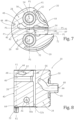
- the adaptor 20 is rotationally oriented about the adaptor axis AA such that the clamping jaw 28 is above the base jaw 26 and the projection of the first plane P1 extends horizontally on the page.
- the pocket axis AP may be parallel to the first plane P1 and extend in a direction coincident with an insertion direction of a cutting insert into the insert receiving pocket 30 .
- the insert receiving pocket 30 may have a stopper surface 36 formed on the base jaw 26 .
- the stopper surface 36 may be transverse to the lower support surface 32 .
- the clamping jaw 28 may be resiliently displaceable relative to the base jaw 26 .
- the tool adaptor 20 is considered to be an "additively manufactured tool adaptor".
- the second plane P2 may intersect the insert receiving pocket's lower support surface 32 and upper clamping surface 34 .
- the second plane P2 may intersect the insert receiving pocket's stopper surface 36 .
- the second plane P2 may be perpendicular to the first plane P1 and the adaptor axis AA .
- the clamping jaw 28 may be resiliently displaceable relative to the rear mounting portion 24 , as well as the base jaw 26 .
- the rear mounting portion 24 may be considered to comprise a first rear sub-portion 24a located axially rearward of (i.e. along the adaptor axis AA ) and spaced apart from the clamping jaw 28 , and a second rear sub-portion 24b located axially rearward of (i.e., along the adaptor axis AA ) and connected to the base jaw 26 .
- configuring the clamping jaw 28 to be resiliently displaceable relative to the rear mounting portion 24 , as well as the base jaw 26 advantageously enables both the first rear sub-portion 24a and the second rear sub-portion 24b to be utilized for mounting the tool adaptor 20 to an interfacing member.
- the rear mounting surface 50 may be at least partially serrated.
- the secondary slot 52 may communicate with the primary slot 42 .
- the resilient axis of rotation AR may intersect the secondary slot 52.
- the rear mounting portion 24 and the clamping jaw 28 may be entirely spaced apart by the secondary slot 52 .
- the rear mounting portion 24 and the clamping jaw 28 may be entirely spaced apart by the secondary slot 52 .
- the secondary slot 52 may have a major secondary slot portion 52a and a minor secondary slot portion 52b , and the minor secondary slot portion 52b may be inclined with respect to the major secondary slot portion 52a .
- a fourth plane P4 perpendicular to the first plane P1 may bisect the major secondary slot portion 52a .
- the slot plane PS may intersect the minor secondary slot portion 52b .
- the base jaw 26 and the rear mounting portion 24 may be configured with an increased level of combined rigidity.
- the secondary slot 52 has an angled configuration
- the rear mounting portion 24 has a first fastening bore 54, and the first fastening bore 54 has a first bore axis A1 which intersects the rear mounting surface 50 and the secondary slot 52 .
- the first bore axis A1 may intersect the clamping jaw 28 .
- the first bore axis A1 may be parallel to the adaptor axis AA .
- the first fastening bore 54 may be a through bore, and the first fastening bore 54 may extend through the rear mounting portion 24 and the clamping jaw 28 .
- the first fastening bore 54 may be a threaded bore, entirely located in the rear mounting portion 24 .
- first fastening bore 54 may be utilized for mounting the tool adaptor 20 to an interfacing member.
- the first fastening bore 54 may include a first front bore portion 54a having a first front diameter FD1 and a first rear bore portion 54b having a first rear diameter RD1.
- first fastening bore 54 may be described as having a stepped configuration.
- the first front bore portion 54a may be coaxial with the first rear bore portion 54b .
- the first rear bore portion 54b may be entirely located in the rear mounting portion 24
- the first front bore portion 54a may be located axially forward of the first rear bore portion 54b (i.e. along the adaptor axis AA )
- the first front diameter FD1 may be greater than the first rear diameter RD1.
- the first rear bore portion 54b may intersect the rear mounting surface 50 .
- the rear mounting portion 24 may have an axially forward-facing first bearing surface 56 , and the first rear bore portion 54b may intersect the first bearing surface 56 .
- first bearing surface 56 may be annular shaped.
- the secondary slot 52 may intersect the first front bore portion 54a .
- the first front bore portion 54a may intersect the clamping jaw front surface 40 .
- the first front bore portion 54a may be circumferentially enclosed by the clamping jaw 28 , and as shown in Fig. 2 , in a front view of the tool adaptor 20 , the entire circumference of the first front bore portion 54a may intersect the clamping jaw front surface 40 .
- first front bore portion 54a may not be circumferentially enclosed by the clamping jaw 28 , and the first front bore portion 54a may circumferentially intersect the clamping jaw peripheral surface 41 .
- the front retaining portion 22 may include a clamping bore 58 extending along a clamping axis AC , and the clamping bore 58 may have first and second clamping bore portions 58a , 58b spaced apart by the primary slot 42 .
- first and second clamping bore portions 58a , 58b may coaxially extend along the clamping axis AC .
- the clamping axis AC may intersect the first plane P1 .
- the front retaining portion 22 may be devoid of a clamping bore 58 , and an external force may be applied to widen the distance between the lower support surface 32 and the upper clamping surface 34 for both insertion and release of a cutting insert, respectively into and from the insert receiving pocket 30 .
- the first clamping bore portion 58a may be a through bore
- the second clamping bore portion 58b may be a threaded bore
- the first clamping bore portion 58a may be formed in the clamping jaw 28
- the second clamping bore portion 58b may be formed in the base jaw 26 .
- the second clamping bore portion 58b may be entirely located axially rearward of the insert receiving pocket 30 (i.e. along the adaptor axis AA ).
- the first clamping bore portion 58a may include a countersunk portion to accommodate a clamping screw head.
- a fifth plane P5 perpendicular to the first plane P1 may contain the first bore axis A1 , and the clamping bore 58 and the insert receiving pocket 30 may be located on the same side of the fifth plane P5 .
- the fifth plane P5 may contain the adaptor axis AA .
- an axial projection of the clamping axis AC may intersect the insert receiving pocket 30 .
- the rear mounting portion 24 may include a second fastening bore 60 , and the second fastening bore 60 may have a second bore axis A2 which intersects the rear mounting surface 50 .
- first fastening bore 54 and the second fastening bore 60 may be located on opposite sides of the slot plane PS .
- the second fastening bore 60 may be a through bore, and the second fastening bore 60 may extend through the rear mounting portion 24 and the base jaw 26 .
- the second bore axis A2 may intersect the base jaw front surface 38 .
- second fastening bore 60 may be utilized for mounting the tool adaptor 20 to an interfacing member.
- the second fastening bore 60 may have a stepped configuration and include a second front bore portion 60a having a second front diameter FD2 and a second rear bore portion 60b having a second rear diameter RD2 .
- the second front bore portion 60a may be located axially forward of the second rear bore portion 60b (i.e. along the adaptor axis AA ), and the second front diameter FD2 may be greater than the second rear diameter RD2 .
- the upper coolant passage 62 may have an upper exit aperture 64 in the clamping jaw peripheral surface 41 adjacent the insert receiving pocket's upper clamping surface 34 .
- the second plane P2 may bisect the upper exit aperture 64 .
- the upper coolant passage 62 may communicate with a central coolant passage 66 extending through the rear mounting portion 24 .
- the central coolant passage 66 may have a rear entry aperture 68 in, or associated with, the rear mounting surface 50 .
- the rear entry aperture 68 may be formed in a rear centering conduit 69 extending rearwardly from the rear mounting surface 50 .
- the rear entry aperture 68 may have a center coincident with the adaptor axis AA .
- the front retaining portion 22 is advantageously configured to provide an efficient route for the upper coolant passage 62 to communicate with the central coolant passage 66 .
- the second plane P2 may bisect the lower exit aperture 72 .
- the first shank bore 82 may be a threaded bore, and the first fastening screw 84 may threadingly engage the first shank bore 82 .
- the sixth plane P6 may be coincident with the second plane P2 .
- the insert peripheral surface 96 may include a rear abutment surface 98 distal from the operative cutting edge 90 .
- the insert receiving pocket's stopper surface 36 may be in abutting contact with the insert's rear abutment surface 98 .
Landscapes
- Engineering & Computer Science (AREA)
- Mechanical Engineering (AREA)
- Cutting Tools, Boring Holders, And Turrets (AREA)
- Turning (AREA)
Applications Claiming Priority (2)
| Application Number | Priority Date | Filing Date | Title |
|---|---|---|---|
| US16/908,796 US11433461B2 (en) | 2020-06-23 | 2020-06-23 | Tool adaptor having an insert receiving pocket and a fastening bore, and cutting tool assembly |
| PCT/IL2021/050631 WO2021260676A1 (en) | 2020-06-23 | 2021-05-27 | Tool adaptor having an insert receiving pocket and a fastening bore, and cutting tool assembly |
Publications (2)
| Publication Number | Publication Date |
|---|---|
| EP4168203A1 EP4168203A1 (en) | 2023-04-26 |
| EP4168203B1 true EP4168203B1 (en) | 2024-07-03 |
Family
ID=76444506
Family Applications (1)
| Application Number | Title | Priority Date | Filing Date |
|---|---|---|---|
| EP21732585.1A Active EP4168203B1 (en) | 2020-06-23 | 2021-05-27 | Tool adaptor having an insert receiving pocket and a fastening bore, and cutting tool assembly |
Country Status (12)
| Country | Link |
|---|---|
| US (1) | US11433461B2 (https=) |
| EP (1) | EP4168203B1 (https=) |
| JP (1) | JP7669392B2 (https=) |
| KR (1) | KR102881989B1 (https=) |
| CN (1) | CN115697598B (https=) |
| CA (1) | CA3178641A1 (https=) |
| ES (1) | ES2991701T3 (https=) |
| IL (1) | IL298339B2 (https=) |
| PL (1) | PL4168203T3 (https=) |
| PT (1) | PT4168203T (https=) |
| TW (1) | TWI884218B (https=) |
| WO (1) | WO2021260676A1 (https=) |
Families Citing this family (7)
| Publication number | Priority date | Publication date | Assignee | Title |
|---|---|---|---|---|
| US11433461B2 (en) * | 2020-06-23 | 2022-09-06 | Iscar, Ltd. | Tool adaptor having an insert receiving pocket and a fastening bore, and cutting tool assembly |
| EP4205889A4 (en) * | 2020-08-31 | 2024-10-09 | Mitsubishi Materials Corporation | GROOVE TOOL |
| US11897038B2 (en) * | 2020-09-30 | 2024-02-13 | Iscar, Ltd. | Curved face grooving blade and face grooving holder therefor |
| US11597019B2 (en) * | 2021-05-03 | 2023-03-07 | Iscar, Ltd. | Slotting tool body having insert receiving slots connected by flexibility recess and rotary slot cutting tool having same |
| WO2023176441A1 (ja) * | 2022-03-14 | 2023-09-21 | 京セラ株式会社 | 切削工具及び切削加工物の製造方法 |
| US11904393B1 (en) * | 2022-08-18 | 2024-02-20 | Iscar, Ltd. | External grooving insert holder having upper and lower jaws connected by angled hinge portion with cooling channel extending through hinge portion, and cutting tool |
| CN115464170B (zh) * | 2022-09-02 | 2023-07-04 | 松德刀具(长兴)科技有限公司 | 用于单刃微调超硬镗刀的滑动刀夹 |
Family Cites Families (31)
| Publication number | Priority date | Publication date | Assignee | Title |
|---|---|---|---|---|
| US5267817A (en) * | 1990-12-18 | 1993-12-07 | Sandvik Ab | Cutting tool |
| SE9004032L (sv) * | 1990-12-18 | 1992-06-19 | Sandvik Ab | Skaerverktyg |
| SE502242C2 (sv) * | 1991-07-31 | 1995-09-25 | Sandvik Ab | Avstickningsverktyg med infästningsdelar orienterade i två mot varandra vinkelräta plan |
| SE505399C2 (sv) * | 1995-11-09 | 1997-08-18 | Sandvik Ab | Fastspänningsförfarande och fastspänningsanordning för skär |
| DE19807498A1 (de) * | 1998-02-21 | 1999-09-02 | Horn P Hartmetall Werkzeugfab | Halter für spanabhebende Werkzeug-Einsätze |
| SE516973C2 (sv) | 1999-02-04 | 2002-03-26 | Sandvik Ab | Verktyg för avstickning och spårsvarvning försett med tandade kopplingsytor |
| US6186704B1 (en) | 1999-03-04 | 2001-02-13 | Kennametal Inc. | Toolholder with detachable blade |
| SE522209C2 (sv) * | 2000-03-02 | 2004-01-20 | Sandvik Ab | Verktyg för spånavskiljande bearbetning med vinklat skärhuvud |
| DE10126043A1 (de) | 2001-05-29 | 2002-12-12 | Horn P Hartmetall Werkzeugfab | Bohrstange |
| SE525462C2 (sv) * | 2002-06-18 | 2005-02-22 | Sandvik Ab | Verktygshuvud för spånavskiljande metallbearbetningsverktyg med spännskruv vilken ingängas i en mutterrulle |
| JP3690675B2 (ja) | 2002-08-13 | 2005-08-31 | 京セラ株式会社 | スローアウェイチップおよびそれを用いた切削工具 |
| SE526767C2 (sv) | 2003-10-16 | 2005-11-01 | Sandvik Intellectual Property | Skärverktyg med tillsatskropp med serrationsyta samt förfarande för tillverkning av skärverktyg |
| SE526536C2 (sv) | 2003-11-19 | 2005-10-04 | Sandvik Intellectual Property | Verktygshuvud med spännanordning i form av en mutterrulle verkande i en slits |
| SE526894C2 (sv) * | 2004-03-03 | 2005-11-15 | Sandvik Intellectual Property | Skärverktyg samt verktygshuvud med rörformig kylmedelskanal |
| SE530579C2 (sv) * | 2006-11-28 | 2008-07-08 | Sandvik Intellectual Property | Verktyg och grundkropp för spånavskiljande bearbetning med flera kanaler |
| SE530581C2 (sv) * | 2006-11-28 | 2008-07-08 | Sandvik Intellectual Property | Verktyg och grundkropp för spånavskiljande innefattande två kanaler för en fluid |
| AT505360B1 (de) * | 2007-05-24 | 2011-09-15 | Boehlerit Gmbh & Co Kg | Schneidwerkzeug mit lösbar befestigten schneidplatten |
| KR100901472B1 (ko) | 2007-07-18 | 2009-06-08 | 대구텍 주식회사 | 모듈형 툴 조립체 |
| JP5309894B2 (ja) * | 2008-10-29 | 2013-10-09 | 三菱マテリアル株式会社 | インサート着脱式切削工具 |
| KR101067161B1 (ko) * | 2010-01-06 | 2011-09-22 | 대구텍 유한회사 | 내경 그루브 가공용 절삭 인서트 및 그를 위한 툴홀더 |
| US8740511B2 (en) * | 2011-12-08 | 2014-06-03 | Iscar, Ltd. | Tool holder and method for clamping a cutting insert therein |
| US20130294854A1 (en) | 2012-05-02 | 2013-11-07 | Taegutec, Ltd. | Cutting tool assembly |
| US9120239B2 (en) * | 2013-02-21 | 2015-09-01 | Iscar, Ltd. | Cutting tool and cutting insert having insert key recesses for extracting and mounting therein |
| JP5660175B2 (ja) | 2013-09-03 | 2015-01-28 | 三菱マテリアル株式会社 | 内径加工工具および内径加工方法 |
| EP2873477A3 (en) * | 2013-11-14 | 2015-12-23 | Sandvik Tooling France | Cartridge for a grooving tool holder, corresponding grooving tool holder, kit and assembly thereof |
| EP3144086B1 (en) * | 2015-09-15 | 2018-05-09 | Sandvik Intellectual Property AB | A tool body and a turning tool for grooving operations |
| DE102016109327A1 (de) * | 2016-05-20 | 2017-11-23 | Hartmetall-Werkzeugfabrik Paul Horn Gmbh | Halter für ein Werkzeug zur spanenden Bearbeitung, insbesondere für ein Langdrehwerkzeug |
| EP3456446B1 (en) * | 2017-09-15 | 2025-11-05 | Sandvik Intellectual Property AB | Cutting tool part assembly |
| DE102018130788A1 (de) * | 2018-12-04 | 2020-06-04 | Hartmetall-Werkzeugfabrik Paul Horn Gmbh | Schneidplatte und Werkzeug zur spanenden Bearbeitung eines Werkstücks |
| DE102019116864A1 (de) * | 2019-06-24 | 2020-12-24 | Zcc Cutting Tools Europe Gmbh | Klemmhalter |
| US11433461B2 (en) * | 2020-06-23 | 2022-09-06 | Iscar, Ltd. | Tool adaptor having an insert receiving pocket and a fastening bore, and cutting tool assembly |
-
2020
- 2020-06-23 US US16/908,796 patent/US11433461B2/en active Active
-
2021
- 2021-02-19 TW TW110105658A patent/TWI884218B/zh active
- 2021-05-27 CA CA3178641A patent/CA3178641A1/en active Pending
- 2021-05-27 IL IL298339A patent/IL298339B2/en unknown
- 2021-05-27 ES ES21732585T patent/ES2991701T3/es active Active
- 2021-05-27 PL PL21732585.1T patent/PL4168203T3/pl unknown
- 2021-05-27 EP EP21732585.1A patent/EP4168203B1/en active Active
- 2021-05-27 CN CN202180044947.0A patent/CN115697598B/zh active Active
- 2021-05-27 PT PT217325851T patent/PT4168203T/pt unknown
- 2021-05-27 WO PCT/IL2021/050631 patent/WO2021260676A1/en not_active Ceased
- 2021-05-27 JP JP2022570221A patent/JP7669392B2/ja active Active
- 2021-05-27 KR KR1020237002148A patent/KR102881989B1/ko active Active
Also Published As
| Publication number | Publication date |
|---|---|
| IL298339A (en) | 2023-01-01 |
| PT4168203T (pt) | 2024-07-24 |
| JP7669392B2 (ja) | 2025-04-28 |
| US20210394278A1 (en) | 2021-12-23 |
| IL298339B1 (en) | 2025-06-01 |
| TWI884218B (zh) | 2025-05-21 |
| ES2991701T3 (es) | 2024-12-04 |
| WO2021260676A1 (en) | 2021-12-30 |
| CN115697598A (zh) | 2023-02-03 |
| TW202200292A (zh) | 2022-01-01 |
| BR112022022639A2 (pt) | 2023-01-03 |
| PL4168203T3 (pl) | 2024-11-04 |
| KR20230028430A (ko) | 2023-02-28 |
| US11433461B2 (en) | 2022-09-06 |
| KR102881989B1 (ko) | 2025-11-10 |
| EP4168203A1 (en) | 2023-04-26 |
| JP2023530587A (ja) | 2023-07-19 |
| CN115697598B (zh) | 2025-10-10 |
| CA3178641A1 (en) | 2021-12-30 |
| IL298339B2 (en) | 2025-10-01 |
Similar Documents
| Publication | Publication Date | Title |
|---|---|---|
| EP4168203B1 (en) | Tool adaptor having an insert receiving pocket and a fastening bore, and cutting tool assembly | |
| EP2428296B1 (en) | Cutting insert | |
| US8479622B2 (en) | Cutting tool assembly and tool holder therefor | |
| EP2229253B1 (en) | Cutting tool | |
| WO2020188555A1 (en) | Insert holder and cutting tool with a resilient insert clamping jaw | |
| US11471953B2 (en) | Double-ended cutting insert having mounting projection with insert upper abutment and insert stopper surfaces | |
| US20230364687A1 (en) | Tool holder having a cylindrical fixation bore extending rearwardly from a front fixation surface and a fastening bore intersecting the front fixation surface | |
| HK40081018A (en) | Tool adaptor having an insert receiving pocket and a fastening bore, and cutting tool assembly | |
| RU2827184C1 (ru) | Адаптер для инструмента, имеющий гнездо для приема режущей пластины и крепежное отверстие, и узел режущего инструмента | |
| WO2009157606A1 (en) | Adjustable double head cutting tool | |
| HK40081018B (zh) | 具有刀片接收凹穴和紧固开孔的工具适配器以及切削工具组件 | |
| BR112022022639B1 (pt) | Adaptador de ferramenta | |
| CN120957826A (zh) | 端铣刀 |
Legal Events
| Date | Code | Title | Description |
|---|---|---|---|
| STAA | Information on the status of an ep patent application or granted ep patent |
Free format text: STATUS: UNKNOWN |
|
| STAA | Information on the status of an ep patent application or granted ep patent |
Free format text: STATUS: THE INTERNATIONAL PUBLICATION HAS BEEN MADE |
|
| PUAI | Public reference made under article 153(3) epc to a published international application that has entered the european phase |
Free format text: ORIGINAL CODE: 0009012 |
|
| STAA | Information on the status of an ep patent application or granted ep patent |
Free format text: STATUS: REQUEST FOR EXAMINATION WAS MADE |
|
| 17P | Request for examination filed |
Effective date: 20230120 |
|
| AK | Designated contracting states |
Kind code of ref document: A1 Designated state(s): AL AT BE BG CH CY CZ DE DK EE ES FI FR GB GR HR HU IE IS IT LI LT LU LV MC MK MT NL NO PL PT RO RS SE SI SK SM TR |
|
| DAV | Request for validation of the european patent (deleted) | ||
| DAX | Request for extension of the european patent (deleted) | ||
| GRAP | Despatch of communication of intention to grant a patent |
Free format text: ORIGINAL CODE: EPIDOSNIGR1 |
|
| STAA | Information on the status of an ep patent application or granted ep patent |
Free format text: STATUS: GRANT OF PATENT IS INTENDED |
|
| INTG | Intention to grant announced |
Effective date: 20240131 |
|
| GRAS | Grant fee paid |
Free format text: ORIGINAL CODE: EPIDOSNIGR3 |
|
| GRAA | (expected) grant |
Free format text: ORIGINAL CODE: 0009210 |
|
| STAA | Information on the status of an ep patent application or granted ep patent |
Free format text: STATUS: THE PATENT HAS BEEN GRANTED |
|
| P01 | Opt-out of the competence of the unified patent court (upc) registered |
Effective date: 20240516 |
|
| AK | Designated contracting states |
Kind code of ref document: B1 Designated state(s): AL AT BE BG CH CY CZ DE DK EE ES FI FR GB GR HR HU IE IS IT LI LT LU LV MC MK MT NL NO PL PT RO RS SE SI SK SM TR |
|
| REG | Reference to a national code |
Ref country code: CH Ref legal event code: EP |
|
| REG | Reference to a national code |
Ref country code: PT Ref legal event code: SC4A Ref document number: 4168203 Country of ref document: PT Date of ref document: 20240724 Kind code of ref document: T Free format text: AVAILABILITY OF NATIONAL TRANSLATION Effective date: 20240718 |
|
| REG | Reference to a national code |
Ref country code: DE Ref legal event code: R096 Ref document number: 602021015204 Country of ref document: DE |
|
| REG | Reference to a national code |
Ref country code: SE Ref legal event code: TRGR |
|
| REG | Reference to a national code |
Ref country code: LT Ref legal event code: MG9D |
|
| REG | Reference to a national code |
Ref country code: NL Ref legal event code: MP Effective date: 20240703 |
|
| REG | Reference to a national code |
Ref country code: ES Ref legal event code: FG2A Ref document number: 2991701 Country of ref document: ES Kind code of ref document: T3 Effective date: 20241204 |
|
| PG25 | Lapsed in a contracting state [announced via postgrant information from national office to epo] |
Ref country code: NL Free format text: LAPSE BECAUSE OF FAILURE TO SUBMIT A TRANSLATION OF THE DESCRIPTION OR TO PAY THE FEE WITHIN THE PRESCRIBED TIME-LIMIT Effective date: 20240703 |
|
| PG25 | Lapsed in a contracting state [announced via postgrant information from national office to epo] |
Ref country code: NL Free format text: LAPSE BECAUSE OF FAILURE TO SUBMIT A TRANSLATION OF THE DESCRIPTION OR TO PAY THE FEE WITHIN THE PRESCRIBED TIME-LIMIT Effective date: 20240703 |
|
| PG25 | Lapsed in a contracting state [announced via postgrant information from national office to epo] |
Ref country code: NO Free format text: LAPSE BECAUSE OF FAILURE TO SUBMIT A TRANSLATION OF THE DESCRIPTION OR TO PAY THE FEE WITHIN THE PRESCRIBED TIME-LIMIT Effective date: 20241003 |
|
| REG | Reference to a national code |
Ref country code: AT Ref legal event code: UEP Ref document number: 1699316 Country of ref document: AT Kind code of ref document: T Effective date: 20240703 |
|
| PG25 | Lapsed in a contracting state [announced via postgrant information from national office to epo] |
Ref country code: FI Free format text: LAPSE BECAUSE OF FAILURE TO SUBMIT A TRANSLATION OF THE DESCRIPTION OR TO PAY THE FEE WITHIN THE PRESCRIBED TIME-LIMIT Effective date: 20240703 Ref country code: GR Free format text: LAPSE BECAUSE OF FAILURE TO SUBMIT A TRANSLATION OF THE DESCRIPTION OR TO PAY THE FEE WITHIN THE PRESCRIBED TIME-LIMIT Effective date: 20241004 |
|
| PG25 | Lapsed in a contracting state [announced via postgrant information from national office to epo] |
Ref country code: BG Free format text: LAPSE BECAUSE OF FAILURE TO SUBMIT A TRANSLATION OF THE DESCRIPTION OR TO PAY THE FEE WITHIN THE PRESCRIBED TIME-LIMIT Effective date: 20240703 |
|
| PG25 | Lapsed in a contracting state [announced via postgrant information from national office to epo] |
Ref country code: LV Free format text: LAPSE BECAUSE OF FAILURE TO SUBMIT A TRANSLATION OF THE DESCRIPTION OR TO PAY THE FEE WITHIN THE PRESCRIBED TIME-LIMIT Effective date: 20240703 |
|
| PG25 | Lapsed in a contracting state [announced via postgrant information from national office to epo] |
Ref country code: IS Free format text: LAPSE BECAUSE OF FAILURE TO SUBMIT A TRANSLATION OF THE DESCRIPTION OR TO PAY THE FEE WITHIN THE PRESCRIBED TIME-LIMIT Effective date: 20241103 |
|
| PG25 | Lapsed in a contracting state [announced via postgrant information from national office to epo] |
Ref country code: HR Free format text: LAPSE BECAUSE OF FAILURE TO SUBMIT A TRANSLATION OF THE DESCRIPTION OR TO PAY THE FEE WITHIN THE PRESCRIBED TIME-LIMIT Effective date: 20240703 |
|
| PG25 | Lapsed in a contracting state [announced via postgrant information from national office to epo] |
Ref country code: RS Free format text: LAPSE BECAUSE OF FAILURE TO SUBMIT A TRANSLATION OF THE DESCRIPTION OR TO PAY THE FEE WITHIN THE PRESCRIBED TIME-LIMIT Effective date: 20241003 |
|
| PG25 | Lapsed in a contracting state [announced via postgrant information from national office to epo] |
Ref country code: RS Free format text: LAPSE BECAUSE OF FAILURE TO SUBMIT A TRANSLATION OF THE DESCRIPTION OR TO PAY THE FEE WITHIN THE PRESCRIBED TIME-LIMIT Effective date: 20241003 Ref country code: NO Free format text: LAPSE BECAUSE OF FAILURE TO SUBMIT A TRANSLATION OF THE DESCRIPTION OR TO PAY THE FEE WITHIN THE PRESCRIBED TIME-LIMIT Effective date: 20241003 Ref country code: LV Free format text: LAPSE BECAUSE OF FAILURE TO SUBMIT A TRANSLATION OF THE DESCRIPTION OR TO PAY THE FEE WITHIN THE PRESCRIBED TIME-LIMIT Effective date: 20240703 Ref country code: IS Free format text: LAPSE BECAUSE OF FAILURE TO SUBMIT A TRANSLATION OF THE DESCRIPTION OR TO PAY THE FEE WITHIN THE PRESCRIBED TIME-LIMIT Effective date: 20241103 Ref country code: HR Free format text: LAPSE BECAUSE OF FAILURE TO SUBMIT A TRANSLATION OF THE DESCRIPTION OR TO PAY THE FEE WITHIN THE PRESCRIBED TIME-LIMIT Effective date: 20240703 Ref country code: GR Free format text: LAPSE BECAUSE OF FAILURE TO SUBMIT A TRANSLATION OF THE DESCRIPTION OR TO PAY THE FEE WITHIN THE PRESCRIBED TIME-LIMIT Effective date: 20241004 Ref country code: FI Free format text: LAPSE BECAUSE OF FAILURE TO SUBMIT A TRANSLATION OF THE DESCRIPTION OR TO PAY THE FEE WITHIN THE PRESCRIBED TIME-LIMIT Effective date: 20240703 Ref country code: BG Free format text: LAPSE BECAUSE OF FAILURE TO SUBMIT A TRANSLATION OF THE DESCRIPTION OR TO PAY THE FEE WITHIN THE PRESCRIBED TIME-LIMIT Effective date: 20240703 |
|
| REG | Reference to a national code |
Ref country code: DE Ref legal event code: R097 Ref document number: 602021015204 Country of ref document: DE |
|
| PGFP | Annual fee paid to national office [announced via postgrant information from national office to epo] |
Ref country code: SE Payment date: 20250314 Year of fee payment: 5 |
|
| PG25 | Lapsed in a contracting state [announced via postgrant information from national office to epo] |
Ref country code: RO Free format text: LAPSE BECAUSE OF FAILURE TO SUBMIT A TRANSLATION OF THE DESCRIPTION OR TO PAY THE FEE WITHIN THE PRESCRIBED TIME-LIMIT Effective date: 20240703 Ref country code: SM Free format text: LAPSE BECAUSE OF FAILURE TO SUBMIT A TRANSLATION OF THE DESCRIPTION OR TO PAY THE FEE WITHIN THE PRESCRIBED TIME-LIMIT Effective date: 20240703 Ref country code: DK Free format text: LAPSE BECAUSE OF FAILURE TO SUBMIT A TRANSLATION OF THE DESCRIPTION OR TO PAY THE FEE WITHIN THE PRESCRIBED TIME-LIMIT Effective date: 20240703 |
|
| PG25 | Lapsed in a contracting state [announced via postgrant information from national office to epo] |
Ref country code: EE Free format text: LAPSE BECAUSE OF FAILURE TO SUBMIT A TRANSLATION OF THE DESCRIPTION OR TO PAY THE FEE WITHIN THE PRESCRIBED TIME-LIMIT Effective date: 20240703 |
|
| PGFP | Annual fee paid to national office [announced via postgrant information from national office to epo] |
Ref country code: CZ Payment date: 20250320 Year of fee payment: 5 |
|
| PG25 | Lapsed in a contracting state [announced via postgrant information from national office to epo] |
Ref country code: SK Free format text: LAPSE BECAUSE OF FAILURE TO SUBMIT A TRANSLATION OF THE DESCRIPTION OR TO PAY THE FEE WITHIN THE PRESCRIBED TIME-LIMIT Effective date: 20240703 |
|
| PGFP | Annual fee paid to national office [announced via postgrant information from national office to epo] |
Ref country code: IT Payment date: 20250321 Year of fee payment: 5 |
|
| PGFP | Annual fee paid to national office [announced via postgrant information from national office to epo] |
Ref country code: TR Payment date: 20250324 Year of fee payment: 5 |
|
| PLBE | No opposition filed within time limit |
Free format text: ORIGINAL CODE: 0009261 |
|
| STAA | Information on the status of an ep patent application or granted ep patent |
Free format text: STATUS: NO OPPOSITION FILED WITHIN TIME LIMIT |
|
| 26N | No opposition filed |
Effective date: 20250404 |
|
| PGFP | Annual fee paid to national office [announced via postgrant information from national office to epo] |
Ref country code: DE Payment date: 20250409 Year of fee payment: 5 |
|
| PGFP | Annual fee paid to national office [announced via postgrant information from national office to epo] |
Ref country code: GB Payment date: 20250411 Year of fee payment: 5 |
|
| PGFP | Annual fee paid to national office [announced via postgrant information from national office to epo] |
Ref country code: FR Payment date: 20250414 Year of fee payment: 5 |
|
| PGFP | Annual fee paid to national office [announced via postgrant information from national office to epo] |
Ref country code: AT Payment date: 20250721 Year of fee payment: 5 |
|
| PGFP | Annual fee paid to national office [announced via postgrant information from national office to epo] |
Ref country code: ES Payment date: 20250708 Year of fee payment: 5 |
|
| REG | Reference to a national code |
Ref country code: CH Ref legal event code: H13 Free format text: ST27 STATUS EVENT CODE: U-0-0-H10-H13 (AS PROVIDED BY THE NATIONAL OFFICE) Effective date: 20251223 |
|
| PG25 | Lapsed in a contracting state [announced via postgrant information from national office to epo] |
Ref country code: LU Free format text: LAPSE BECAUSE OF NON-PAYMENT OF DUE FEES Effective date: 20250527 |
|
| PG25 | Lapsed in a contracting state [announced via postgrant information from national office to epo] |
Ref country code: CH Free format text: LAPSE BECAUSE OF NON-PAYMENT OF DUE FEES Effective date: 20250531 |
|
| REG | Reference to a national code |
Ref country code: BE Ref legal event code: MM Effective date: 20250531 |
|
| PG25 | Lapsed in a contracting state [announced via postgrant information from national office to epo] |
Ref country code: MC Free format text: LAPSE BECAUSE OF FAILURE TO SUBMIT A TRANSLATION OF THE DESCRIPTION OR TO PAY THE FEE WITHIN THE PRESCRIBED TIME-LIMIT Effective date: 20240703 |
|
| PG25 | Lapsed in a contracting state [announced via postgrant information from national office to epo] |
Ref country code: IE Free format text: LAPSE BECAUSE OF NON-PAYMENT OF DUE FEES Effective date: 20250527 |
|
| PG25 | Lapsed in a contracting state [announced via postgrant information from national office to epo] |
Ref country code: BE Free format text: LAPSE BECAUSE OF NON-PAYMENT OF DUE FEES Effective date: 20250531 |
|
| PGFP | Annual fee paid to national office [announced via postgrant information from national office to epo] |
Ref country code: PT Payment date: 20260327 Year of fee payment: 6 |
|
| PGFP | Annual fee paid to national office [announced via postgrant information from national office to epo] |
Ref country code: PL Payment date: 20260327 Year of fee payment: 6 |