EP4166495A2 - Vorrichtung zum erwärmen und flüssigkeitsabgabevorrichtung - Google Patents
Vorrichtung zum erwärmen und flüssigkeitsabgabevorrichtung Download PDFInfo
- Publication number
- EP4166495A2 EP4166495A2 EP22207212.6A EP22207212A EP4166495A2 EP 4166495 A2 EP4166495 A2 EP 4166495A2 EP 22207212 A EP22207212 A EP 22207212A EP 4166495 A2 EP4166495 A2 EP 4166495A2
- Authority
- EP
- European Patent Office
- Prior art keywords
- fluid
- nozzle
- air
- hose
- tube
- Prior art date
- Legal status (The legal status is an assumption and is not a legal conclusion. Google has not performed a legal analysis and makes no representation as to the accuracy of the status listed.)
- Pending
Links
- 239000012530 fluid Substances 0.000 title claims abstract description 333
- 238000010438 heat treatment Methods 0.000 title claims abstract description 281
- 239000000446 fuel Substances 0.000 claims abstract description 183
- 238000012546 transfer Methods 0.000 claims description 23
- 239000003570 air Substances 0.000 description 338
- 230000008878 coupling Effects 0.000 description 50
- 238000010168 coupling process Methods 0.000 description 50
- 238000005859 coupling reaction Methods 0.000 description 50
- 230000007246 mechanism Effects 0.000 description 34
- 238000004891 communication Methods 0.000 description 27
- 230000008014 freezing Effects 0.000 description 26
- 238000007710 freezing Methods 0.000 description 26
- 238000000034 method Methods 0.000 description 24
- 239000000463 material Substances 0.000 description 16
- 239000012080 ambient air Substances 0.000 description 6
- 238000004519 manufacturing process Methods 0.000 description 6
- 230000013011 mating Effects 0.000 description 6
- 230000008439 repair process Effects 0.000 description 6
- XSQUKJJJFZCRTK-UHFFFAOYSA-N Urea Chemical compound NC(N)=O XSQUKJJJFZCRTK-UHFFFAOYSA-N 0.000 description 5
- 230000000712 assembly Effects 0.000 description 5
- 238000000429 assembly Methods 0.000 description 5
- 230000004044 response Effects 0.000 description 5
- 238000007789 sealing Methods 0.000 description 5
- QGZKDVFQNNGYKY-UHFFFAOYSA-N Ammonia Chemical compound N QGZKDVFQNNGYKY-UHFFFAOYSA-N 0.000 description 4
- 239000004202 carbamide Substances 0.000 description 4
- 239000003638 chemical reducing agent Substances 0.000 description 4
- 238000005086 pumping Methods 0.000 description 4
- 230000009471 action Effects 0.000 description 3
- 230000000694 effects Effects 0.000 description 3
- 239000000203 mixture Substances 0.000 description 3
- 238000012545 processing Methods 0.000 description 3
- 238000011144 upstream manufacturing Methods 0.000 description 3
- XLYOFNOQVPJJNP-UHFFFAOYSA-N water Substances O XLYOFNOQVPJJNP-UHFFFAOYSA-N 0.000 description 3
- 239000004593 Epoxy Substances 0.000 description 2
- 239000004809 Teflon Substances 0.000 description 2
- 229920006362 Teflon® Polymers 0.000 description 2
- 239000000853 adhesive Substances 0.000 description 2
- 230000001070 adhesive effect Effects 0.000 description 2
- 229910052782 aluminium Inorganic materials 0.000 description 2
- XAGFODPZIPBFFR-UHFFFAOYSA-N aluminium Chemical compound [Al] XAGFODPZIPBFFR-UHFFFAOYSA-N 0.000 description 2
- 230000004888 barrier function Effects 0.000 description 2
- 230000008901 benefit Effects 0.000 description 2
- 230000008859 change Effects 0.000 description 2
- 229920001940 conductive polymer Polymers 0.000 description 2
- 239000004020 conductor Substances 0.000 description 2
- 239000002828 fuel tank Substances 0.000 description 2
- 230000006870 function Effects 0.000 description 2
- 239000007789 gas Substances 0.000 description 2
- 229910052751 metal Inorganic materials 0.000 description 2
- 239000002184 metal Substances 0.000 description 2
- 230000001681 protective effect Effects 0.000 description 2
- 238000009420 retrofitting Methods 0.000 description 2
- VHUUQVKOLVNVRT-UHFFFAOYSA-N Ammonium hydroxide Chemical compound [NH4+].[OH-] VHUUQVKOLVNVRT-UHFFFAOYSA-N 0.000 description 1
- IJGRMHOSHXDMSA-UHFFFAOYSA-N Atomic nitrogen Chemical compound N#N IJGRMHOSHXDMSA-UHFFFAOYSA-N 0.000 description 1
- RYGMFSIKBFXOCR-UHFFFAOYSA-N Copper Chemical compound [Cu] RYGMFSIKBFXOCR-UHFFFAOYSA-N 0.000 description 1
- 244000007853 Sarothamnus scoparius Species 0.000 description 1
- 230000002411 adverse Effects 0.000 description 1
- 229910021529 ammonia Inorganic materials 0.000 description 1
- 238000013459 approach Methods 0.000 description 1
- 239000003054 catalyst Substances 0.000 description 1
- 230000003197 catalytic effect Effects 0.000 description 1
- 238000010531 catalytic reduction reaction Methods 0.000 description 1
- 238000006243 chemical reaction Methods 0.000 description 1
- 238000004140 cleaning Methods 0.000 description 1
- 229910052802 copper Inorganic materials 0.000 description 1
- 239000010949 copper Substances 0.000 description 1
- 239000013078 crystal Substances 0.000 description 1
- 238000002425 crystallisation Methods 0.000 description 1
- 230000008025 crystallization Effects 0.000 description 1
- 230000007123 defense Effects 0.000 description 1
- 239000002283 diesel fuel Substances 0.000 description 1
- -1 e.g. Substances 0.000 description 1
- 231100001261 hazardous Toxicity 0.000 description 1
- 238000005259 measurement Methods 0.000 description 1
- 150000002739 metals Chemical class 0.000 description 1
- 238000012986 modification Methods 0.000 description 1
- 230000004048 modification Effects 0.000 description 1
- 230000007659 motor function Effects 0.000 description 1
- 230000006903 response to temperature Effects 0.000 description 1
- 238000005096 rolling process Methods 0.000 description 1
- 229910001220 stainless steel Inorganic materials 0.000 description 1
- 239000010935 stainless steel Substances 0.000 description 1
- 238000012360 testing method Methods 0.000 description 1
- 230000007704 transition Effects 0.000 description 1
- 239000002699 waste material Substances 0.000 description 1
- 238000003466 welding Methods 0.000 description 1
Images


Classifications
-
- B—PERFORMING OPERATIONS; TRANSPORTING
- B67—OPENING, CLOSING OR CLEANING BOTTLES, JARS OR SIMILAR CONTAINERS; LIQUID HANDLING
- B67D—DISPENSING, DELIVERING OR TRANSFERRING LIQUIDS, NOT OTHERWISE PROVIDED FOR
- B67D7/00—Apparatus or devices for transferring liquids from bulk storage containers or reservoirs into vehicles or into portable containers, e.g. for retail sale purposes
- B67D7/06—Details or accessories
- B67D7/80—Arrangements of heating or cooling devices for liquids to be transferred
- B67D7/82—Heating only
-
- B—PERFORMING OPERATIONS; TRANSPORTING
- B67—OPENING, CLOSING OR CLEANING BOTTLES, JARS OR SIMILAR CONTAINERS; LIQUID HANDLING
- B67D—DISPENSING, DELIVERING OR TRANSFERRING LIQUIDS, NOT OTHERWISE PROVIDED FOR
- B67D7/00—Apparatus or devices for transferring liquids from bulk storage containers or reservoirs into vehicles or into portable containers, e.g. for retail sale purposes
- B67D7/02—Apparatus or devices for transferring liquids from bulk storage containers or reservoirs into vehicles or into portable containers, e.g. for retail sale purposes for transferring liquids other than fuel or lubricants
-
- B—PERFORMING OPERATIONS; TRANSPORTING
- B67—OPENING, CLOSING OR CLEANING BOTTLES, JARS OR SIMILAR CONTAINERS; LIQUID HANDLING
- B67D—DISPENSING, DELIVERING OR TRANSFERRING LIQUIDS, NOT OTHERWISE PROVIDED FOR
- B67D7/00—Apparatus or devices for transferring liquids from bulk storage containers or reservoirs into vehicles or into portable containers, e.g. for retail sale purposes
- B67D7/04—Apparatus or devices for transferring liquids from bulk storage containers or reservoirs into vehicles or into portable containers, e.g. for retail sale purposes for transferring fuels, lubricants or mixed fuels and lubricants
-
- B—PERFORMING OPERATIONS; TRANSPORTING
- B67—OPENING, CLOSING OR CLEANING BOTTLES, JARS OR SIMILAR CONTAINERS; LIQUID HANDLING
- B67D—DISPENSING, DELIVERING OR TRANSFERRING LIQUIDS, NOT OTHERWISE PROVIDED FOR
- B67D7/00—Apparatus or devices for transferring liquids from bulk storage containers or reservoirs into vehicles or into portable containers, e.g. for retail sale purposes
- B67D7/06—Details or accessories
- B67D7/32—Arrangements of safety or warning devices; Means for preventing unauthorised delivery of liquid
- B67D7/3218—Arrangements of safety or warning devices; Means for preventing unauthorised delivery of liquid relating to emergency shut-off means
-
- B—PERFORMING OPERATIONS; TRANSPORTING
- B67—OPENING, CLOSING OR CLEANING BOTTLES, JARS OR SIMILAR CONTAINERS; LIQUID HANDLING
- B67D—DISPENSING, DELIVERING OR TRANSFERRING LIQUIDS, NOT OTHERWISE PROVIDED FOR
- B67D7/00—Apparatus or devices for transferring liquids from bulk storage containers or reservoirs into vehicles or into portable containers, e.g. for retail sale purposes
- B67D7/06—Details or accessories
- B67D7/42—Filling nozzles
- B67D7/425—Filling nozzles including components powered by electricity or light
-
- F—MECHANICAL ENGINEERING; LIGHTING; HEATING; WEAPONS; BLASTING
- F16—ENGINEERING ELEMENTS AND UNITS; GENERAL MEASURES FOR PRODUCING AND MAINTAINING EFFECTIVE FUNCTIONING OF MACHINES OR INSTALLATIONS; THERMAL INSULATION IN GENERAL
- F16L—PIPES; JOINTS OR FITTINGS FOR PIPES; SUPPORTS FOR PIPES, CABLES OR PROTECTIVE TUBING; MEANS FOR THERMAL INSULATION IN GENERAL
- F16L53/00—Heating of pipes or pipe systems; Cooling of pipes or pipe systems
- F16L53/30—Heating of pipes or pipe systems
- F16L53/32—Heating of pipes or pipe systems using hot fluids
-
- H—ELECTRICITY
- H05—ELECTRIC TECHNIQUES NOT OTHERWISE PROVIDED FOR
- H05B—ELECTRIC HEATING; ELECTRIC LIGHT SOURCES NOT OTHERWISE PROVIDED FOR; CIRCUIT ARRANGEMENTS FOR ELECTRIC LIGHT SOURCES, IN GENERAL
- H05B3/00—Ohmic-resistance heating
- H05B3/40—Heating elements having the shape of rods or tubes
- H05B3/54—Heating elements having the shape of rods or tubes flexible
- H05B3/58—Heating hoses; Heating collars
-
- F—MECHANICAL ENGINEERING; LIGHTING; HEATING; WEAPONS; BLASTING
- F16—ENGINEERING ELEMENTS AND UNITS; GENERAL MEASURES FOR PRODUCING AND MAINTAINING EFFECTIVE FUNCTIONING OF MACHINES OR INSTALLATIONS; THERMAL INSULATION IN GENERAL
- F16L—PIPES; JOINTS OR FITTINGS FOR PIPES; SUPPORTS FOR PIPES, CABLES OR PROTECTIVE TUBING; MEANS FOR THERMAL INSULATION IN GENERAL
- F16L53/00—Heating of pipes or pipe systems; Cooling of pipes or pipe systems
- F16L53/30—Heating of pipes or pipe systems
- F16L53/35—Ohmic-resistance heating
- F16L53/38—Ohmic-resistance heating using elongate electric heating elements, e.g. wires or ribbons
-
- H—ELECTRICITY
- H05—ELECTRIC TECHNIQUES NOT OTHERWISE PROVIDED FOR
- H05B—ELECTRIC HEATING; ELECTRIC LIGHT SOURCES NOT OTHERWISE PROVIDED FOR; CIRCUIT ARRANGEMENTS FOR ELECTRIC LIGHT SOURCES, IN GENERAL
- H05B2203/00—Aspects relating to Ohmic resistive heating covered by group H05B3/00
- H05B2203/021—Heaters specially adapted for heating liquids
-
- Y—GENERAL TAGGING OF NEW TECHNOLOGICAL DEVELOPMENTS; GENERAL TAGGING OF CROSS-SECTIONAL TECHNOLOGIES SPANNING OVER SEVERAL SECTIONS OF THE IPC; TECHNICAL SUBJECTS COVERED BY FORMER USPC CROSS-REFERENCE ART COLLECTIONS [XRACs] AND DIGESTS
- Y02—TECHNOLOGIES OR APPLICATIONS FOR MITIGATION OR ADAPTATION AGAINST CLIMATE CHANGE
- Y02T—CLIMATE CHANGE MITIGATION TECHNOLOGIES RELATED TO TRANSPORTATION
- Y02T10/00—Road transport of goods or passengers
- Y02T10/10—Internal combustion engine [ICE] based vehicles
- Y02T10/12—Improving ICE efficiencies
Definitions
- Heated cabinets for fuel dispensers have been developed to help prevent fluid from freezing outdoors.
- the heated cabinets can be aesthetically unpleasing, can be cumbersome by being large and/or unwieldy, and/or can provide inefficient heating.
- Another approach that has been developed to help prevent fluid from freezing outdoors has been to contain a hose and/or nozzle of the fuel dispenser within a shroud.
- the shroud can be aesthetically unpleasing, can be cumbersome by getting in the way of a user's handling of the fuel dispenser, and/or can provide inefficient heating.
- a fluid dispensing device in one embodiment includes a hose, a heating element, and a nozzle.
- the hose can have first and second passageways extending longitudinally therein.
- the first passageway can be configured to pass fluid therethrough.
- the second passageway can be independent from the first passageway.
- the heating element can extend longitudinally within the second passageway.
- the heating element can be configured to heat fluid within the first passageway.
- the nozzle can be attached to a distal end of the hose.
- the first passageway can extend therein such that fluid is allowed to exit a distal opening of the first passageway to be dispensed from the nozzle.
- a fuel dispensing device in another embodiment, includes a hose, a heat element, and a nozzle.
- the hose can have first and second passageways extending longitudinally therethrough.
- the first passageway can be configured to pass fluid therethrough
- the second passageway can be adjacent to and independent from the first passageway
- the second passageway can be configured to pass air therethrough.
- the heat element can be in communication with the second passageway and can be configured to heat the air passing through the second passageway, thereby heating the fluid within the first passageway that is adjacent the second passageway.
- the nozzle can be attached to a distal end of the hose.
- a fuel dispensing method in one embodiment includes allowing passage of fluid through a first passageway of a fuel dispensing system and out of the fuel dispensing system through a nozzle of the fuel dispensing system, and forcing heated air through a second passageway of the fuel dispensing system.
- the second passageway can be disposed within the first passageway, a sidewall defining the second passageway can prevent the heated air within the second passageway from mixing with the fluid within the first passageway, the heated air can heat the fluid within the first passageway, and the heated air can pass through the fuel dispensing system through the nozzle.
- a fluid dispensing device can include a first passageway configured to pass fluid therethrough and can include a second passageway fluidically isolated from the first passageway and having a heating element disposed therein.
- the heating element can be configured to heat the fluid passing through the first passageway.
- the fluid can be configured to be heated from within the hose and the nozzle, which can allow the fluid to be heated without any external heating components being visible to the user dispensing the fluid, thereby allowing for a more visually appealing fuel dispenser and/or allowing the fluid to be heated without heating-related components being physically in the user's way when the user is dispensing the fluid so as to make using the dispenser cumbersome and/or require user movement of a shroud before dispensing fluid. Because the heat source that heats the fluid can be very close to the fluid, as opposed to various traditional heating techniques such as heated cabinets, lower wattage can be used to heat the fluid, thereby reducing adverse effects of thermodynamic loss, improving efficiency, saving energy, and/or reducing monetary cost.
- the fuel dispensing devices described herein can be configured to dispense any kind of fluid, as will be appreciated by a person skilled in the art.
- the fluid can include a fuel of any type of ammonia/water blend usable in automobiles.
- the fuel dispensing devices described herein can be configured to dispense diesel exhaust fluid (DEF), e.g., AdBlue ® .
- DEF diesel exhaust fluid
- AUS32 is generally sold under the trade mark of AdBlue ®
- the trade name for AUS32 is diesel exhaust fluid or DEF. Accordingly, the terms AUS32, AdBlue ® , and DEF used herein refer to the same material.
- the fuel dispensing device can thus dispense the fluid 104 on demand in accordance with a user's typical expectations of fluid dispensing, e.g., at a gas station, while also providing for heating of the fluid 104 so as to reduce chances of the fluid 104 freezing within the hose 100 and/or within the nozzle 102.
- a gap of space 122 can be defined between an inner surface 123 of the outer tube 120 and an outer surface 125 of the inner tube 124.
- the space 122 also referred to herein as a "fluid cavity” and an “fluid passageway,” can be configured to pass the fluid 104 therethrough.
- the fluid 104 can be configured to be selectively advanced through the space 122 in response to user actuation of the trigger 108, as will be appreciated by a person skilled in the art.
- the air 106 that enters the intake opening 132 can be heated.
- the air entering the intake opening 132 can come from a supply of heated air.
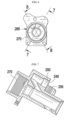
- the manifold in this illustrated embodiment includes a first opening 348 through which air can flow, a first coupling element 350 configured to mate with an air supply, a second opening 354 through which fluid can flow, a second coupling element 356 configured to mate with a fluid supply, a fourth opening 368 through which the air and the fluid can flow and through which a heating element can extend, and a fourth coupling element 370 configured to mate with a hose.
- the first opening 348 can be configured to also have the heating element control cable extend therethrough.
- the first coupling element 350 includes a thread
- the second coupling element 356 includes a thread
- the fourth coupling element 366 includes a tube.
- the manifold in this illustrated embodiment is a non-unitary, multi-piece member.
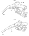
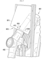
- FIGS. 16-20 illustrate another embodiment of a fuel dispensing device 401 configured to heat fluid (not shown) that can be dispensed therefrom.
- the device 401 can include a hose 400, a nozzle 402, a heating element (not shown), a movable element 414, and a manifold 430.
- the hose 400 can be configured as a coaxial hose and include at least two coaxial tubes, e.g., an outer tube 420 and an inner tube (not shown).
- the nozzle 402 can include a dispensing trigger 408, a fluid exit opening 410, and an air exit opening 412. Like the nozzle 102 of FIG. 1 , the nozzle 402 of FIGS.
- the fuel dispensing device can include a conduit disposed within the fuel dispensing device, e.g., within a housing thereof, that can include the air exit opening located adjacent to a nozzle boot of the fuel dispensing device.
- the heated air that flows through the conduit can include ambient air from within the housing that has already been heated within the housing, such that the conduit can be configured to redirect the heated air toward the nozzle.
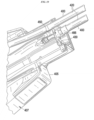
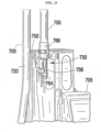
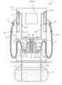
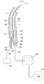
- FIG. 30 illustrates an embodiment of a fuel dispensing device 1 including a first conduit 9 disposed within the fuel dispensing device 1 and having an air exit opening 19 located adjacent to a nozzle boot 12 of the fuel dispensing device 1.
- the device 1 can include a hose 4, a nozzle 5, a fluid supply 14, and a fluid meter 20.
- the device 1 can also include a housing 21 generally divided into an electronics compartment 2 and a hydraulics compartment 3.
- the hose 4 can include coaxial passageways therein to facilitate the heating of the fuel.
- the fuel can circulate in a direction from the inner fluid reservoir 15 toward the nozzle 5 in an inner one of the coaxial passageways, as shown by first circulation arrows 22, and can circulate in a direction toward the inner fluid reservoir 15 in an outer one of the coaxial passageways, as shown by first circulation arrows 23.
- the sensed temperature can be used, e.g., by the electronics in the electronics compartment 2, to control an amount of heat provided by the heating element 6, thereby controlling how much the fuel is heated. For example, if the sensed temperature is within a first predetermined range of temperatures, the heating element 6 can provide a first level of heat, and if the sensed temperature is within a second predetermined range of temperatures that are lower than the first predetermined range, the heating element 6 can provide a second level of heat that is greater than the first level of heat.
- the sensed temperature can be used, e.g., by the electronics in the electronics compartment 2, to control a flow rate of the circulated fuel in the hose 4, e.g., by controlling a power output of the motor 8.
- the fuel dispensing unit 1 can include a proportional valve (not shown) configured to facilitate control of the flow rate.
- the higher the motor's power output the higher the fuel's flow rate within the hose 4 and the more heated the fuel.
- the motor 8 can provide a first amount of power output, and if the sensed temperature is below the predetermined threshold temperature, the motor 8 can provide a second amount of power output that is greater than the first amount of power output.
- the heating element 6, the motor 8, and a fan 7 can be configured to cooperate to provide and transport heated air through the first conduit 9 and out the air exit opening 19.
- the fan 7 and the motor 8 are separate, independent elements, but the fan 7 and the motor 8 can be part of a single unit providing both fan and motor functions.
- the first conduit 9 includes a rigid elongate tube in this illustrated embodiment, but the first conduit 9 can have other configurations, such as a flexible elongate tube.
- the first conduit 9 can be configured to pass heated air from within the housing 21 to the nozzle boot 12 in a direction of conduit arrows 25, thereby facilitating the heating of the nozzle 5 when the nozzle 5 is seated in the nozzle boot 5.
- the motor 8 can be configured to drive the fan 7.
- the motor 8 can thus be configured to drive the circulation of the fuel through the hose 4 and to drive the flow of heated air through the first conduit 9.
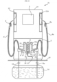
- the heated air passing through the second conduit 10 can be ambient air from within the housing 21, e.g., from within the hydraulics compartment 3. In this way, a separate air supply need not be provided.
- the heating element 6 can be located upstream of the fan 7b, as in this illustrated embodiment, such that air drawn by the fan 7b into the second conduit 10 has been in proximity of the heating element 6 so as to have been heated by the heating element 6 before being drawn into the second conduit 10. In this way, heated air can enter the second conduit 10 through the proximal opening 28 thereof that is in communication with the heating element 6.
- a sensed temperature can be used to control the starting and stopping of the heated air's passing into the second conduit 10 (e.g., by starting and stopping the fan 7b); can be used to control an amount of heat provided by the heating element 6, thereby controlling how much the air in the second conduit 10 is heated; and/or can be used to control a flow rate of the heated air within the second conduit 10 (e.g., by controlling a rotation speed of the fan 7b).
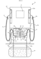
- FIG. 32 illustrates another embodiment of a fuel dispensing device 1c configured to heat a housing 21 thereof.
- the fuel dispensing device 1c of FIG. 32 is similar to the fuel dispensing device 1 of FIG. 30 and has like-named and like-numbered components accordingly.
- the fuel dispensing device 1c includes a third conduit 11 that, in general, can be configured to facilitate the heating of the housing 21 by passing heated air therethrough and out a distal opening 29 thereof that is located within the housing 21, e.g., within the hydraulics compartment 3 of the housing 21.
- a proximal end of the third conduit 11 can be in communication with the heating element 6 such that air adjacent to the heating element 6 can pass into the third conduit 11 through a proximal opening 30 of the third conduit 11.
- the heated air passing through the third conduit 11 can be ambient air from within the housing 21, e.g., from within the hydraulics compartment 3. In this way, a separate air supply need not be provided.
- the heating element 6 can be located upstream of the fan 7c, as in this illustrated embodiment, such that air drawn by the fan 7c into the third conduit 11 has been in proximity of the heating element 6 so as to have been heated by the heating element 6 before being drawn into the third conduit 11. In this way, heated air can enter the third conduit 11 through the proximal opening 30 thereof that is in communication with the heating element 6.
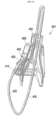
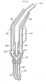
- FIG. 33 illustrates an embodiment of a heating assembly 1100 configured to be included in a fluid dispensing device and to heat fluid dispensable therefrom.
- the heating assembly 1100 has a proximal portion that is configured to be disposed in a hose of the fluid dispensing system and a distal portion that is configured to be disposed in a nozzle coupled to a distal end of the hose, as discussed further below.
- a proximal portion that is configured to be disposed in a hose of the fluid dispensing system and a distal portion that is configured to be disposed in a nozzle coupled to a distal end of the hose, as discussed further below.
- Such a configuration allows the heating assembly 1100 to heat fluid within both the hose and the nozzle.
- the distal-most end of the jacket 1112 can be configured to be rolled or folded into itself and secured around the electrical leads 1114.
- the jacket's distal end can be temporarily heated to facilitate the rolling thereof around the leads 1114.
- the distal ends of the electrical leads 1114 (e.g., about 0.25 in. thereof) can be trimmed or otherwise removed, as shown in FIG. 35 , such that the leads 1114 terminate at a location proximal to the distal folded end of the jacket.
- the folded or rolled end with thus act as an additional barrier, and it can also help provide room for the stopper 1116 to be secured within the distal end of the jacket 1112.
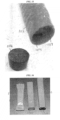
- a heating element 1200 can include a jacket 1202 having a distal end 1202d that is ultrasonically welded to form a seal.
- the jacket's proximal end 1202p is similarly sealed in the illustrated embodiment, but the proximal end 1202p can be left open to facilitate connection of the heating element's electrical leads 1204 to a source of electrical power.
- FIG. 36 also shows the jacket 1202 as a standalone element (pre-seal) to the left of the sealed heating element 1200, and to the left of the standalone element, the jacket 1202 (pre-seal) having the electrical leads 1204 disposed therein.
- the hollowed interior 1118h has an inner diameter that closely conforms to an outer diameter of the heating element 1106 such that the components are in direct contact with one another to facilitate the transfer of heat.
- the heat transfer element can include or be in the form of a heat transfer epoxy or a heat transfer paste that is delivered into the well 1108 around the heating element 1106.
- the well 1108 can have a closed distal end, which can facilitate containment of the epoxy or the paste within the outer extension tube 1102.
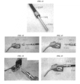
- the nozzle 1304 in this illustrated embodiment includes an OPW 19DEF nozzle, but as mentioned herein, other types of nozzles can be attached to the heating assembly 1100 and to other embodiments of heating assemblies described herein. As shown in FIGS. 45 and 46 , the heating assembly 1100 can be configured to be entirely contained within the nozzle 1304 and the hose 1300.
- FIGS. 47-51 illustrate the hose 1300 and the swivel 1302 of FIGS. 42-46 with another embodiment of an outer extension tube 1400 that is part of a heating assembly (a reminder of which is obscured in FIGS. 47-51 ) and another embodiment of a nozzle 1306 having a proximal end configured to attach to the swivel 1302.
- the nozzle 1306 in the illustrated embodiment is a OPW 21GU nozzle, but as mentioned herein, other types of nozzles can be attached to this heating assembly and to other embodiments of heating assemblies described herein.
- the nozzle 1306 of FIGS. 47-51 has a smaller amount of space available at a proximal end thereof than the nozzle 1304 of FIGS. 42-46 .
- FIG. 52 illustrates a system including the power supply and control 144 of FIG. 2 configured to provide power to a heating element 1502 of a heating assembly that also includes an outer extension tube (not shown), an optional heat transfer element (not shown), and an outer tube 1500 having the heating element 1502 extending longitudinally through an inner passageway 1504 thereof.
- the system of FIG. 52 is similar to the system of FIG. 2 except that it includes the heating assembly and does not include the inner tube 124 of the hose 100, the air supply, or air flowing through the outer tube 120 of hose 100.
- FIG. 53 illustrates another embodiment of a system including another embodiment of a power supply and control 1600 configured to provide power to a heating element 1602 of a heating assembly that also includes an outer extension tube 1604, an optional heat transfer element (not shown), and an outer tube 1606 having the heating element 1602 extending longitudinally through an inner passageway 1608 thereof.
- the system also includes a hose 1610, a nozzle 1612 configured to have the outer extension tube 1604 disposed substantially therein and configured to couple to a distal end of the hose 1610, a swivel 1614 configured to couple the hose 1610 and the nozzle 1612 together, and a fluid meter 1616.
Landscapes
- Engineering & Computer Science (AREA)
- Mechanical Engineering (AREA)
- General Engineering & Computer Science (AREA)
- Loading And Unloading Of Fuel Tanks Or Ships (AREA)
- Fuel-Injection Apparatus (AREA)
- Pipe Accessories (AREA)
Applications Claiming Priority (8)
| Application Number | Priority Date | Filing Date | Title |
|---|---|---|---|
| US201461981577P | 2014-04-18 | 2014-04-18 | |
| US14/286,405 US10597285B2 (en) | 2014-04-18 | 2014-05-23 | Devices and methods for heating fuel hoses and nozzles |
| US201462078220P | 2014-11-11 | 2014-11-11 | |
| US14/568,729 US9637370B2 (en) | 2014-04-18 | 2014-12-12 | Devices and methods for heating fluid dispensers, hoses, and nozzles |
| US14/678,486 US11174148B2 (en) | 2014-04-18 | 2015-04-03 | Devices and methods for heating fluid dispensers, hoses, and nozzles |
| PCT/US2015/025583 WO2015160710A1 (en) | 2014-04-18 | 2015-04-13 | Devices and methods for heating fluid dispensers, hoses, and nozzles |
| EP19179500.4A EP3564183B1 (de) | 2014-04-18 | 2015-04-13 | Vorrichtung zur erwärmung von flüssigkeitsspendern, schläuchen und düsen |
| EP15722297.7A EP3131845B1 (de) | 2014-04-18 | 2015-04-13 | Vorrichtungen und verfahren zur erwärmung von flüssigkeitsspendern, schläuchen und düsen |
Related Parent Applications (2)
| Application Number | Title | Priority Date | Filing Date |
|---|---|---|---|
| EP15722297.7A Division EP3131845B1 (de) | 2014-04-18 | 2015-04-13 | Vorrichtungen und verfahren zur erwärmung von flüssigkeitsspendern, schläuchen und düsen |
| EP19179500.4A Division EP3564183B1 (de) | 2014-04-18 | 2015-04-13 | Vorrichtung zur erwärmung von flüssigkeitsspendern, schläuchen und düsen |
Publications (2)
| Publication Number | Publication Date |
|---|---|
| EP4166495A2 true EP4166495A2 (de) | 2023-04-19 |
| EP4166495A3 EP4166495A3 (de) | 2023-07-12 |
Family
ID=54321387
Family Applications (3)
| Application Number | Title | Priority Date | Filing Date |
|---|---|---|---|
| EP22207212.6A Pending EP4166495A3 (de) | 2014-04-18 | 2015-04-13 | Vorrichtung zum erwärmen und flüssigkeitsabgabevorrichtung |
| EP19179500.4A Active EP3564183B1 (de) | 2014-04-18 | 2015-04-13 | Vorrichtung zur erwärmung von flüssigkeitsspendern, schläuchen und düsen |
| EP15722297.7A Active EP3131845B1 (de) | 2014-04-18 | 2015-04-13 | Vorrichtungen und verfahren zur erwärmung von flüssigkeitsspendern, schläuchen und düsen |
Family Applications After (2)
| Application Number | Title | Priority Date | Filing Date |
|---|---|---|---|
| EP19179500.4A Active EP3564183B1 (de) | 2014-04-18 | 2015-04-13 | Vorrichtung zur erwärmung von flüssigkeitsspendern, schläuchen und düsen |
| EP15722297.7A Active EP3131845B1 (de) | 2014-04-18 | 2015-04-13 | Vorrichtungen und verfahren zur erwärmung von flüssigkeitsspendern, schläuchen und düsen |
Country Status (6)
| Country | Link |
|---|---|
| US (1) | US11174148B2 (de) |
| EP (3) | EP4166495A3 (de) |
| CN (3) | CN106458565B (de) |
| CA (3) | CA2946196C (de) |
| PT (1) | PT3131845T (de) |
| WO (1) | WO2015160710A1 (de) |
Families Citing this family (14)
| Publication number | Priority date | Publication date | Assignee | Title |
|---|---|---|---|---|
| CN102725223B (zh) | 2009-11-09 | 2015-03-18 | 韦恩加油系统瑞典公司 | 具有循环系统的流体分配单元和用于使流体在流体分配单元中循环的方法 |
| US20170022992A1 (en) * | 2014-03-07 | 2017-01-26 | Daniel Jutras | Pump shelter |
| US10597285B2 (en) | 2014-04-18 | 2020-03-24 | Wayne Fueling Systems Llc | Devices and methods for heating fuel hoses and nozzles |
| CN106884700A (zh) * | 2015-12-15 | 2017-06-23 | 珠海格力智能装备有限公司 | 车用尿素溶液的供液设备及包含其的车用尿素的生产系统 |
| KR101767013B1 (ko) | 2016-10-25 | 2017-08-23 | 전배용 | 혼유 방지 주유장치 |
| CN106966353B (zh) * | 2017-04-24 | 2019-05-14 | 北京牧晨机电有限公司 | 全自动流体装车鹤管及其应用 |
| JP7069597B2 (ja) * | 2017-08-10 | 2022-05-18 | トヨタ自動車株式会社 | 高圧容器 |
| US11235341B2 (en) * | 2018-05-01 | 2022-02-01 | Rheem Manufacturing Company | Heated hose nozzle |
| US11969742B2 (en) | 2018-05-01 | 2024-04-30 | Rheem Manufacturing Company | Heated hose nozzle |
| CA3097966A1 (en) * | 2018-05-09 | 2019-11-14 | Wayne Fueling Systems Llc | Fluid dispensing unit having a defrosting system |
| WO2019246270A1 (en) * | 2018-06-19 | 2019-12-26 | Diebolt Mark C | Thermal controlled hose assembly for dispensing fluid |
| US20200383177A1 (en) * | 2019-05-31 | 2020-12-03 | Graco Minnesota Inc. | Sensor free heated hose |
| US11668438B2 (en) * | 2020-03-30 | 2023-06-06 | Hyundai Motor Company | Fluid charging system, nozzle device, and receptacle device |
| USD944363S1 (en) * | 2020-08-03 | 2022-02-22 | Great Plains Industries, Inc. | Fuel nozzle |
Citations (1)
| Publication number | Priority date | Publication date | Assignee | Title |
|---|---|---|---|---|
| WO2011054400A1 (en) | 2009-11-09 | 2011-05-12 | Dresser Wayne Ab | Fluid dispensing unit having a circulation system and a method for circulating a fluid in a fluid dispensing unit |
Family Cites Families (66)
| Publication number | Priority date | Publication date | Assignee | Title |
|---|---|---|---|---|
| US1252614A (en) | 1917-04-24 | 1918-01-08 | Oscar H Pieper | Hot-air syringe. |
| US1809714A (en) | 1929-04-01 | 1931-06-09 | Mathews Carl Raymond | Heated water hose for filling stations |
| US2526405A (en) | 1945-11-26 | 1950-10-17 | Vilbiss Co | Spray head |
| US2801323A (en) | 1955-05-26 | 1957-07-30 | Heron Andrew George | Flexible hoses |
| US3378673A (en) * | 1965-10-18 | 1968-04-16 | Thomas O. Hopper | Electrically heated hose assembly |
| US3754118A (en) * | 1971-02-12 | 1973-08-21 | A Booker | Flexible immersion heater |
| US3784785A (en) * | 1971-09-20 | 1974-01-08 | W Noland | Electrically heated fluid conduit coupler |
| US3832525A (en) | 1973-03-26 | 1974-08-27 | Raymond Lee Organization Inc | Automatic heating device to prevent freezing of water supply lines |
| US3968346A (en) * | 1973-06-01 | 1976-07-06 | Cooksley Ralph D | Method and apparatus for electrically heating a fluid |
| US3932727A (en) * | 1973-12-11 | 1976-01-13 | Cecil Wayne True | Electrically heated riser pipe for a fluid supply system |
| EP0017057B1 (de) * | 1979-03-27 | 1982-03-10 | Danfoss A/S | Vorrichtung zum Vorwärmen von Heizöl |
| US4372279A (en) | 1980-11-24 | 1983-02-08 | Paccar Inc. | Heated fuel line |
| US4926028A (en) | 1983-03-01 | 1990-05-15 | Fortune William S | Hot air heated soldering instrument |
| US4551619A (en) * | 1985-01-22 | 1985-11-05 | Lefebvre Fredrick L | Cable structure for immersion heaters or the like |
| US4808793A (en) | 1986-11-13 | 1989-02-28 | Everhot Corporation | Tankless electric water heater with instantaneous hot water output |
| US4883943A (en) * | 1987-12-16 | 1989-11-28 | Davco Manufacturing Corporation | Electric heater for fuel tank discharge opening coupling to prevent fuel waxing |
| US5355915A (en) | 1990-12-11 | 1994-10-18 | Gilbarco | Vapor recovery improvements |
| US6899149B1 (en) | 1990-12-11 | 2005-05-31 | Gilbarco Inc. | Vapor recovery fuel dispenser for multiple hoses |
| US5195564A (en) | 1991-04-30 | 1993-03-23 | Dresser Industries, Inc. | Gasoline dispenser with vapor recovery system |
| US5285826A (en) | 1992-03-11 | 1994-02-15 | Dayco Products, Inc. | Fuel dispensing system, hose assembly and couplings therefore and methods of making the same |
| US5351727A (en) | 1994-01-18 | 1994-10-04 | Dayco Products Inc. | Fuel dispensing system, hose assembly therefor and methods of making the same |
| US5600752A (en) * | 1994-03-11 | 1997-02-04 | Industrial Design Laboratories, Inc. | Flexible gas hose assembly with concentric helical tube members having reinforcement spring coils |
| US5807332A (en) * | 1994-03-22 | 1998-09-15 | Augustine Medical, Inc. | Tube apparatus for warming intravenous fluids within an air hose |
| US5542458A (en) | 1994-08-22 | 1996-08-06 | Gilbarco Inc. | Vapor recovery system for a fuel delivery system |
| US5782275A (en) | 1996-05-17 | 1998-07-21 | Gilbarco Inc. | Onboard vapor recovery detection |
| US5832178A (en) * | 1996-06-25 | 1998-11-03 | Crafco, Incorporated | Hot melt mix applicator with electrically heated hose and wand with temperature-controlled electric generator |
| US5868175A (en) | 1996-06-28 | 1999-02-09 | Franklin Electric Co., Inc. | Apparatus for recovery of fuel vapor |
| US5859953A (en) | 1997-06-30 | 1999-01-12 | Nickless; Eugene R. | Electric heating apparatus for deicing pipes utilizing flexible heated hose inserted into pipe |
| US5933574A (en) * | 1998-02-09 | 1999-08-03 | Avansino; Gary L. | Heated fluid conduit |
| TW417148B (en) | 1998-07-02 | 2001-01-01 | Tokyo Electron Ltd | Process solution supplying apparatus and fluid passageway opening-closing valve device for process solution supplying apparatus |
| US6109826A (en) * | 1999-06-03 | 2000-08-29 | Cimline, Inc. | Melter and applicator for applying filling material to paved surfaces |
| US6386246B2 (en) | 1999-11-17 | 2002-05-14 | Marconi Commerce Systems Inc. | Vapor flow and hydrocarbon concentration sensor for improved vapor recovery in fuel dispensers |
| US6135359A (en) * | 1999-12-22 | 2000-10-24 | Wcm Industries, Inc. | Heated yard hydrant |
| US6357493B1 (en) | 2000-10-23 | 2002-03-19 | Marconi Commerce Systems Inc. | Vapor recovery system for a fuel dispenser |
| US6835223B2 (en) * | 2002-02-06 | 2004-12-28 | Vapor Systems Technologies, Inc. | Fuel storage and dispensing system |
| US6915638B2 (en) | 2002-03-28 | 2005-07-12 | Parker-Hannifin Corporation | Nozzle with fluted tube |
| US6953354B2 (en) * | 2002-06-05 | 2005-10-11 | Fisher & Paykel Healthcare Limited | Connector for breathing conduits |
| GB0219373D0 (en) * | 2002-08-20 | 2002-09-25 | Heat Trace Ltd | Heated conduit |
| US6710302B1 (en) | 2002-10-31 | 2004-03-23 | Mark Rennick | Vehicle sensor assembly including integral heating unit |
| US7396995B2 (en) * | 2003-09-19 | 2008-07-08 | Fisher & Paykel Healthcare Limited | Connector |
| US6810922B1 (en) | 2003-10-10 | 2004-11-02 | Vapor Systems Technologies, Inc. | Vapor recovery system with improved ORVR compatibility and performance |
| US6923221B2 (en) | 2003-12-04 | 2005-08-02 | Gilbarco Inc. | Vapor recovery system with ORVR compensation |
| DE202005010318U1 (de) | 2005-07-01 | 2005-09-08 | Car Go Green Gmbh | System zur Abgabe von zwei unterschiedlichen Brennstoffarten an einer Tankstelle |
| SE529417C2 (sv) | 2005-12-22 | 2007-08-07 | Volvo Lastvagnar Ab | Ledningsnät för ett fordon |
| US20070212037A1 (en) * | 2006-03-03 | 2007-09-13 | Andreas Koenekamp | Heating element and mounting for media piping of fuel cell systems |
| DE102006015601A1 (de) * | 2006-04-04 | 2007-10-18 | Hydac System Gmbh | Einrichtung zum Beeinflussen der Temperatur strömungsfähiger Medien, insbesondere von in einem Schmierstoffsystem befindlichen Schmierstoffen |
| CN201024081Y (zh) | 2007-02-16 | 2008-02-20 | 江阴市富仁高科有限公司 | 具有电加热及防爆功能的加油机 |
| TWI478772B (zh) | 2007-09-11 | 2015-04-01 | Graco Minnesota Inc | 螺旋加熱軟管 |
| EP2075218A1 (de) | 2007-12-19 | 2009-07-01 | Tokheim Holding B.V. | Anlage zum Zapfen eines Additifs auf Harnstoffbasis zur Schadstoffverringerung für Kraftfahrzeuge |
| US8752597B2 (en) | 2008-09-17 | 2014-06-17 | Franklin Fueling Systems, Inc. | Fuel dispensing nozzle |
| DE202009012230U1 (de) * | 2009-06-23 | 2010-11-04 | Voss Automotive Gmbh | Elektrisch beheizbare Medienleitung sowie Leitungsverbinder |
| WO2011085154A1 (en) * | 2010-01-08 | 2011-07-14 | Parker-Hannifin Corporation | Electrically-heated hose assembly for selective catalytic reduction (scr) systems |
| US8604392B1 (en) * | 2010-03-05 | 2013-12-10 | Arctic Innovations | Hydration systems and methods |
| DE102010032188A1 (de) | 2010-07-23 | 2012-01-26 | Voss Automotive Gmbh | Beheizbare Medienleitung |
| US8733590B2 (en) | 2010-07-27 | 2014-05-27 | Gilbarco, Inc. | Fuel or DEF dispenser having fluid temperature conditioning and control system |
| DE102010053737A1 (de) * | 2010-12-08 | 2012-06-14 | Voss Automotive Gmbh | Beheizbare Fluidleitung, deren Verwendung sowie Verfahren zu ihrer Herstellung |
| ES2702314T3 (es) | 2011-01-27 | 2019-02-28 | St Clair Systems Inc | Sistema de manguera coaxial recuperable |
| CN202139039U (zh) | 2011-07-12 | 2012-02-08 | 北京长吉加油设备有限公司 | 一种用于加油机的加热装置 |
| CN202132648U (zh) | 2011-07-21 | 2012-02-01 | 徐霆生 | 管道加热系统 |
| US8931499B2 (en) | 2011-11-23 | 2015-01-13 | Opw Fueling Components Inc. | Ball and socket breakaway connector |
| WO2014140939A2 (en) | 2013-03-15 | 2014-09-18 | Certek Heat Machine Inc. | Pipeline heater |
| DE202013006358U1 (de) | 2013-07-15 | 2013-07-30 | Gilbarco Gmbh & Co. Kg | Zapfanlagensystem |
| FR3012442B1 (fr) * | 2013-10-31 | 2015-11-20 | Tokheim Holding Bv | Distributeur de liquide destine a des vehicules et procede mis en oeuvre lors du fonctionnement d'un tel distributeur. |
| DE202014000767U1 (de) | 2014-01-29 | 2014-02-11 | Gilbarco Gmbh & Co. Kg | Schlauch für eine Zapfsäule |
| US10597285B2 (en) | 2014-04-18 | 2020-03-24 | Wayne Fueling Systems Llc | Devices and methods for heating fuel hoses and nozzles |
| US9637370B2 (en) | 2014-04-18 | 2017-05-02 | Wayne Fueling Systems Llc | Devices and methods for heating fluid dispensers, hoses, and nozzles |
-
2015
- 2015-04-03 US US14/678,486 patent/US11174148B2/en active Active
- 2015-04-13 EP EP22207212.6A patent/EP4166495A3/de active Pending
- 2015-04-13 PT PT15722297T patent/PT3131845T/pt unknown
- 2015-04-13 CN CN201580032515.2A patent/CN106458565B/zh active Active
- 2015-04-13 CA CA2946196A patent/CA2946196C/en active Active
- 2015-04-13 EP EP19179500.4A patent/EP3564183B1/de active Active
- 2015-04-13 EP EP15722297.7A patent/EP3131845B1/de active Active
- 2015-04-13 CA CA3073722A patent/CA3073722C/en active Active
- 2015-04-13 CN CN202010533224.4A patent/CN111732064B/zh active Active
- 2015-04-13 CN CN202210847326.2A patent/CN115285921A/zh active Pending
- 2015-04-13 CA CA2958716A patent/CA2958716C/en active Active
- 2015-04-13 WO PCT/US2015/025583 patent/WO2015160710A1/en active Application Filing
Patent Citations (1)
| Publication number | Priority date | Publication date | Assignee | Title |
|---|---|---|---|---|
| WO2011054400A1 (en) | 2009-11-09 | 2011-05-12 | Dresser Wayne Ab | Fluid dispensing unit having a circulation system and a method for circulating a fluid in a fluid dispensing unit |
Also Published As
| Publication number | Publication date |
|---|---|
| EP4166495A3 (de) | 2023-07-12 |
| WO2015160710A1 (en) | 2015-10-22 |
| US20150298962A1 (en) | 2015-10-22 |
| CA3073722C (en) | 2023-03-28 |
| CN111732064A (zh) | 2020-10-02 |
| CN106458565A (zh) | 2017-02-22 |
| CA2958716A1 (en) | 2015-10-22 |
| EP3564183A1 (de) | 2019-11-06 |
| EP3564183B1 (de) | 2022-11-16 |
| CN111732064B (zh) | 2022-08-09 |
| CA2946196A1 (en) | 2015-10-22 |
| CN115285921A (zh) | 2022-11-04 |
| US11174148B2 (en) | 2021-11-16 |
| CA3073722A1 (en) | 2015-10-22 |
| PT3131845T (pt) | 2019-09-26 |
| CA2946196C (en) | 2017-08-15 |
| CN106458565B (zh) | 2020-05-22 |
| EP3131845B1 (de) | 2019-06-12 |
| EP3131845A1 (de) | 2017-02-22 |
| CA2958716C (en) | 2020-06-23 |
Similar Documents
| Publication | Publication Date | Title |
|---|---|---|
| US11174148B2 (en) | Devices and methods for heating fluid dispensers, hoses, and nozzles | |
| US11964864B2 (en) | Devices and methods for heating fuel hoses and nozzles | |
| US9637370B2 (en) | Devices and methods for heating fluid dispensers, hoses, and nozzles | |
| US11027966B2 (en) | Fluid dispensing unit having a circulation system and a method for circulating a fluid in a fluid dispensing unit | |
| ES2626412T3 (es) | Dispositivo de termonebulización de un líquido y procedimiento asociado | |
| US9764938B2 (en) | Heating system for a urea dispenser | |
| EP2738442A3 (de) | Wärmeregelungssystem und -verfahren für Systeme zur Abgabe kryogener Flüssigkeiten | |
| ES2378273T3 (es) | Dispositivo y procedimiento de termonebulización de un líquido | |
| US8857473B2 (en) | Apparatus and method for deicing | |
| ES1065093U (es) | Surtidor para el liquido de lavado del parabrisas de vehiculos automoviles. |
Legal Events
| Date | Code | Title | Description |
|---|---|---|---|
| PUAI | Public reference made under article 153(3) epc to a published international application that has entered the european phase |
Free format text: ORIGINAL CODE: 0009012 |
|
| STAA | Information on the status of an ep patent application or granted ep patent |
Free format text: STATUS: THE APPLICATION HAS BEEN PUBLISHED |
|
| AC | Divisional application: reference to earlier application |
Ref document number: 3131845 Country of ref document: EP Kind code of ref document: P Ref document number: 3564183 Country of ref document: EP Kind code of ref document: P |
|
| AK | Designated contracting states |
Kind code of ref document: A2 Designated state(s): AL AT BE BG CH CY CZ DE DK EE ES FI FR GB GR HR HU IE IS IT LI LT LU LV MC MK MT NL NO PL PT RO RS SE SI SK SM TR |
|
| PUAL | Search report despatched |
Free format text: ORIGINAL CODE: 0009013 |
|
| AK | Designated contracting states |
Kind code of ref document: A3 Designated state(s): AL AT BE BG CH CY CZ DE DK EE ES FI FR GB GR HR HU IE IS IT LI LT LU LV MC MK MT NL NO PL PT RO RS SE SI SK SM TR |
|
| RIC1 | Information provided on ipc code assigned before grant |
Ipc: F16L 53/32 20180101ALI20230602BHEP Ipc: H05B 3/54 20060101ALI20230602BHEP Ipc: F16L 53/00 20180101ALI20230602BHEP Ipc: B67D 7/82 20100101ALI20230602BHEP Ipc: B67D 7/42 20100101ALI20230602BHEP Ipc: B67D 7/32 20100101ALI20230602BHEP Ipc: B67D 7/02 20100101AFI20230602BHEP |
|
| STAA | Information on the status of an ep patent application or granted ep patent |
Free format text: STATUS: REQUEST FOR EXAMINATION WAS MADE |
|
| 17P | Request for examination filed |
Effective date: 20240103 |
|
| RBV | Designated contracting states (corrected) |
Designated state(s): AL AT BE BG CH CY CZ DE DK EE ES FI FR GB GR HR HU IE IS IT LI LT LU LV MC MK MT NL NO PL PT RO RS SE SI SK SM TR |