EP4166197B1 - Sicherheitsleinenhalterung, auffangsystem für personen und verfahren für eine sicherheitsleinenhalterung - Google Patents
Sicherheitsleinenhalterung, auffangsystem für personen und verfahren für eine sicherheitsleinenhalterung Download PDFInfo
- Publication number
- EP4166197B1 EP4166197B1 EP21202996.1A EP21202996A EP4166197B1 EP 4166197 B1 EP4166197 B1 EP 4166197B1 EP 21202996 A EP21202996 A EP 21202996A EP 4166197 B1 EP4166197 B1 EP 4166197B1
- Authority
- EP
- European Patent Office
- Prior art keywords
- safety line
- support
- ring
- connecting part
- shaped elements
- Prior art date
- Legal status (The legal status is an assumption and is not a legal conclusion. Google has not performed a legal analysis and makes no representation as to the accuracy of the status listed.)
- Active
Links
Images


Classifications
-
- A—HUMAN NECESSITIES
- A62—LIFE-SAVING; FIRE-FIGHTING
- A62B—DEVICES, APPARATUS OR METHODS FOR LIFE-SAVING
- A62B35/00—Safety belts or body harnesses; Similar equipment for limiting displacement of the human body, especially in case of sudden changes of motion
- A62B35/0043—Lifelines, lanyards, and anchors therefore
- A62B35/0068—Anchors
-
- A—HUMAN NECESSITIES
- A62—LIFE-SAVING; FIRE-FIGHTING
- A62B—DEVICES, APPARATUS OR METHODS FOR LIFE-SAVING
- A62B35/00—Safety belts or body harnesses; Similar equipment for limiting displacement of the human body, especially in case of sudden changes of motion
- A62B35/0081—Equipment which can travel along the length of a lifeline, e.g. travelers
- A62B35/0087—Arrangements for bypassing lifeline supports without lanyard disconnection
Definitions
- the invention relates to a height safety system and more particularly to a safety line support for anchoring the safety system to a structure of a building or other construction.
- the invention further relates to a personnel fall-arrest system and a method for supporting a safety line.
- An object of the invention is to provide a novel and improved safety line support, personnel fall-arrest system, and method for supporting a safety line to a fixed structure of a construction.
- the safety line support according to the invention is characterized by the characterizing features of the first independent apparatus claim.
- the personnel fall-arrest system according to the invention is characterized by the characterizing features of the second independent apparatus claim.
- the method according to the invention is characterized by the characterizing features of the independent method claim.
- the safety line support comprises a connecting part through which safety line is arrangeable so that the connecting part is configured to surround the safety line, and a bracket part supporting the connecting part and comprising fastening means for anchoring the safety line support to a structure of a construction.
- the support has a single piece configuration, and it is formed of sheet material.
- the connecting part comprises at least two ring-shaped elements having a common axial central line and being located at an axial distance from each other so that there is an empty space between the two ring-shaped elements. The at least two ring-shaped elements are configured to be clamped around the safety line whereby the safety line is mounted immovably relative to the support.
- the safety line passes through two or more ring-shaped elements and is visible at the empty spaces between the ring-shaped elements.
- the connecting part is not provided with one single tube, tubular element, or continuous longitudinal opening, but instead, there are several shorter elements discontinuously arranged so that they together form a longitudinal passage for the safety line.
- An advantage of the disclosed solution is that the several ring-shaped elements clamp properly around the safety line and provide firm connection between the support and the safety line. Since the connecting part comprises several ring-shaped elements, it withstands well possible deforming forces in fall situations.
- a further advantage of the disclosed solution is that manufacture of the disclosed safety line support is easy and inexpensive.
- width of the empty space of the connecting part of the safety line support is at least twofold compared to width of the ring-shaped element.
- width of the empty space is at least threefold.
- the safety line is anchored to the connecting part and is thereby immovably mounted.
- the safety line support has a symmetrical structure.
- An advantage of this is that the symmetrical safety line support operates properly in different orientations and positions.
- the connecting part has an open position for receiving the safety line in transverse direction inside the ring shaped elements, and a closed position wherein the safety line is locked immovably inside the connecting part.
- the safety line is easy and quick to push laterally inside the open connecting part, compared to a solution where the safety line needs to be threaded through the connecting part for the remaining length of the safety line.
- the connecting part is forced to the open position by means of an internal spring force based on a bend plate material of the support.
- the structure is provided with a self-opening structure, which is normally open and is configured to be pressed into the closed position by means of separate fastening screws or corresponding force elements after the safety line is mounted in place.
- the connecting part comprises in its open position an opening, or an open gap, which is dimensioned so that the safety line can be pushed easily inside the connecting part and it remains inside there temporarily without easily escaping out of there. Since the safety line remains inside the connecting part with this temporary hold, mounting of the safety line is facilitated. Final mounting of the safety line is executed by pressing the structure into the closed position.
- each of the mentioned ring-shaped elements of the connecting part is provided with a lateral mounting opening facing towards the bracket part.
- the safety line is mountable inside a free space limited by the ring-shaped element through the lateral mounting opening when the connecting part is in the open position.
- the connecting part further comprises a locking plate protruding laterally adjacent the mounting opening. The locking plate is configured to be forced against the bracket part by means of fastening screws for closing the mounting opening, and for setting the connecting part into the closed position.
- the connecting part can be reopened, and the safety line can be removed from the support.
- the support can be demounted from the fixed structure and can be remounted to a new location.
- the safety line may be remounted respectively to a new location.
- shape of an inner surface of each ring-shaped element is circular in a closed position of the connecting part.
- the ring shaped element has cylindrical configuration wherein outer and inner cylinder surfaces are flat surfaces.
- transverse dimensions of each ring shaped element are dimensioned in accordance with transverse dimensions of the safety line so that in the closed position of the connecting part a press coupling is formed between the coupling part and the safety line.
- the ring-shaped element comprises an inner diameter in the closed position and the safety line has a substantially circular cross-section with an outer diameter.
- the inner diameter of the ring-shaped element in the closed position may be dimensioned to be slightly smaller compared to an outer diameter of the safety line.
- the support comprises three ring-shaped elements, whereby the support comprises two edge rings, an intermediate ring between them, and two empty spaces.
- the support comprises at least one tooth which is located between the ring-shaped elements and is facing towards the safety line mountable inside the ring-shaped elements.
- Number of the teeth may be 2 - 4, for example.
- the locking plate comprises at least one first fastening opening and the bracket comprises at least one second fastening opening whereby at least one fastening screw is mountable through the openings and is configured to move the locking plate against the bracket in response to tightening of the fastening screw.
- the locking plate has slanted orientation in the opened position of the connecting part. Further, the tightening of the fastening screw is configured to generate pressing force to the locking plate and is configured to press the slanted upper surface of the locking plate downwards and is configured to simultaneously generate lateral force component for the ring-shaped elements towards the bracket portion thereby generating tightening lateral forces to the ring-shaped elements of the coupling part.
- shape of the at least one first fastening opening of the locking plate is elongated and is orientated so that its longitudinal axis is transverse to the axial direction of the connecting part. Then, relative lateral movement between the fastening screw and the locking plate is possible when the slanted locking plate is turned from the opened position to the closed position.
- the disclosed support can be mounted with conventional hand tools, such as with battery driven screw drivers. No special tools and skills are needed in the mounting measures.
- the locking plate of the support comprises opposite slanted axial end surfaces whereby the locking plate tapers towards its free end.
- the bracket of the support comprises a mounting part provided with at least one through opening for anchoring screws whereby the support is mountable to the fixed structure by means of screw fastening.
- the support is mountable in place by means of conventional hand tools.
- the connection of the safety wire is based on screw tightening, whereby the entire system is easy and fast to mount by means of normal tools and the mounting requires no special skills.
- the disclosed solution relates to a personnel fall-arrest system.
- the system comprises: at least one safety line; two or more safety line supports for mounting the system to a fixed structure of a construction; at least one safety harness for at least one user; at least one glider mounted movably to the safety line and allowed to pass the supports; and at least one lifeline for connecting the glider to the safety harness.
- the safety line support is in accordance with the features and embodiments disclosed in this document.
- the safety line extends as a continuous element between several supports belonging to the system.
- the safety line is a metal wire.
- the safety line is a stainless steel wire.
- diameter of the safety line is 4-14 mm.
- the system is without any separate end terminals at distal ends of the safety line. That is because the supports are fixed to the safety line and can thereby serve as a kind of end terminals.
- the system is easy to reposition. Then the connecting elements of the supports are opened, and the safety line is removed from the support. Thereafter, the supports are removed and mounted to a new place.
- the supports are mountable to an accessory structure of a roof of a building, wherein the accessory structure is a service bridge, walkway, or ladder.
- the supports can be alternatively mounted directly to a roof or wall structure, or cladding.
- the roof or wall cladding may comprise several metallic panels fixed on a roof or wall of a building. Also, in this case the supports are mounted to a fixed structure.
- the system is dimensioned to withstand load of several simultaneous users. In other words, multiple users can be simultaneously attached to the system.
- the disclosed solution relates to a method for supporting a safety line to a structure of a construction.
- the method comprises: fastening at least two safety line supports to the fixed structure at a distance from each other; and coupling a safety line to connecting parts of the supports.
- the method further comprises using supports provided with at least two ring-shaped elements at their connecting parts and forming a press coupling with the safety line and the support by pressing the ring shaped elements against the safety line.
- strengthening grip between the safety wire and the support by means of at least one tooth on inner surface side of the connecting part of each support.
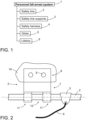
- Figure 1 discloses basic components of a personnel fall-arrest system 1.
- the system system comprises one or more safety lines 2 which can be mounted to a building or corresponding construction by means of two or more safety line supports 3.
- a user wears a safety harness 4 which is connectable to the safety line 2 by means of a glider 5 and a lifeline 6.
- the glider can slide along the safety line 2 in accordance with normal movements of the user on a walkway, for example. If the user falls, then the user is supported by the system.
- the glider is designed so that it can pass the safety line supports.
- the safety line may be long and there may be several supports at designed distances from each other.
- One or more user may be connected to the same system.
- Figure 2 discloses a safety line support 3 comprising a connecting part 7 through which a safety line 2 is arranged.
- the support 3 further comprises a bracket part 8 for supporting the connecting part 7 and comprising fastening means 9 for anchoring the support 3 to a structure of a construction 10.
- the fastening means may comprise holes, screws, rivets, or other mechanical fastening elements for providing permanent or releasable mounting.
- the connecting part 7 and the bracket part 8 are inseparately connected to each other i.e., the support 3 has a single piece construction.
- the support 3 is made of sheet material by means or normal bending, cutting and other sheet metal work processes and tools.
- the support 3 may be made of steel material, such as stainless steel.
- the connecting part 7 comprises two ring-shaped elements 11 having a common axial central line and being located at an axial distance from each other so that there is an empty space 12 between the two ring-shaped elements 11.
- the ring-shaped elements 11 are clamped around the safety line 2 so that the safety line 2 is immovable relative to the support 3.
- An advantage of the ring-shaped elements 11 is that when their width is relatively narrow, they deform relatively easily and can therefore be pressed against the safety line for producing the effective clamping.
- Figure 3 discloses a connecting part 7 of another support 3.
- Further, at the empty spaces 12 may be teeth 13a, 13b or other protruding elements, or shapes for further intensifying fastening strength of the safety line.
- the teeth may be located on the inner and/or side surfaces of the ring-shaped elements.
- the connecting part 7 is in its closed position CP wherein lateral mounting openings 14 are closed.
- the connecting part 7 can be closed by pressing a locking plate 16 against the bracket part 8 by means of fastening screws 17.
- the locking plate 16 comprises one or more first fastening openings 18 and the bracket part 8 comprises one or more second fastening openings 19 whereby one or more fastening screws 17 can be mounted and screwed through the openings 18, 19 for moving the locking plate 16.
- the locking plate 16 has slanted orientation in the opened position OP of the connecting part 7.
- tightening of the fastening screw (not shown) generates pressing force to the locking plate 16 and thereby presses the locking plate 16 downwards.
- lateral force component F shown in Figure 3
- This tightening lateral force F is shown in Figure 3 .
- Figure 3 further discloses that the locking plate 16 may comprise slanted axial end surfaces 20. Then the locking plate 16 tapers towards its free end. The slanted surfaces facilitate the glider to pass the support 3.
- Figure 4 discloses a support 3 wherein a connecting part 7 comprises four ring-shaped elements 11.
- the bracket part 8 may comprise a mounting part 21 provided with one or more through openings for anchoring screws 9, 22 whereby the support 3 is mountable to the fixed structure by means of screw fastening.
- Figure 7 shows a connecting part 7 of a support 3 in an open position OP.
- a safety line 2 is inserted inside ring-shaped elements 11 through their mounting openings 14. Diameter of the safety line 2 is slightly greater than size of the mounting openings 14. The safety line 2 can still be pushed inside the ring-shaped elements 11 since a locking plate 16 may yield and allow the mounting. The safety line 2 stays inside the coupling part 7 temporarily until the final fastening is done. This way mounting is quickened and facilitated.
- Figure 8 shown that a protrusion or tooth 13 may move together with a locking plate 16 and may be pushed in a closed position CP against a safety line 2.
Landscapes
- Health & Medical Sciences (AREA)
- General Health & Medical Sciences (AREA)
- Business, Economics & Management (AREA)
- Emergency Management (AREA)
- Emergency Lowering Means (AREA)
Claims (14)
- Sicherheitsleinenhalterung (3), umfassend:einen Verbindungsteil (7), durch den eine Sicherheitsleine (2) angeordnet werden kann, so dass der Verbindungsteil (7) dazu eingerichtet ist, die Sicherheitsleine (2) zu umgeben; undeinen Bügelteil (8), der den Verbindungsteil (7) trägt und Befestigungsmittel (9) zur Verankerung der Sicherheitsleinenhalterung (3) an einer Struktur eines Bauwerks (10) umfasst;dadurch gekennzeichnet, dassdie Halterung (3) eine einteilige Ausgestaltung aufweist und aus flächigem Material gebildet ist;der Verbindungsteil (7) mindestens zwei ringförmige Elemente (11) umfasst, die eine gemeinsame axiale Mittellinie aufweisen und in einem axialen Abstand zueinander angeordnet sind, so dass zwischen den beiden ringförmigen Elementen (11) ein Leerraum (12) vorhanden ist;die mindestens zwei ringförmigen Elemente (11) dazu eingerichtet sind, um die Sicherheitsleine (2) geklemmt zu werden, wodurch die Sicherheitsleine (2) unbeweglich relativ zu der Halterung (3) montiert ist;und wobei die Halterung (3) mindestens einen Zahn (13, 13a, 13b) aufweist, der der Sicherheitsleine (2) zugewandt ist, um den Halt zwischen der Sicherheitsleine (2) und der Halterung (3) zu verstärken, und wobei der mindestens eine Zahn (13, 13a, 13b) zwischen den ringförmigen Elementen (11), auf der Innenfläche des ringförmigen Elements (11) oder auf den Seitenflächen der ringförmigen Elemente angeordnet ist.
- Halterung nach Anspruch 1, dadurch gekennzeichnet, dass
der Verbindungsteil (7) eine offene Position (OP) zur Aufnahme der Sicherheitsleine (2) in Querrichtung innerhalb der ringförmigen Elemente (11) und eine geschlossene Position (CP) aufweist, in der die Sicherheitsleine (2) unbeweglich in dem Verbindungsteil (7) verriegelt ist. - Halterung nach Anspruch 2, dadurch gekennzeichnet, dassjedes der ringförmigen Elemente (11) des Verbindungsteils mit einer seitlichen Montageöffnung (14) versehen ist, die dem Bügelteil (8) zugewandt ist;die Sicherheitsleine (2) innerhalb eines durch das ringförmige Element (11) begrenzten Freiraums (15) durch die seitliche Montageöffnung (14) montierbar ist, wenn sich der Verbindungsteil (7) in der offenen Position (OP) befindet;der Verbindungsteil (7) ferner eine Verriegelungsplatte (16) umfasst, die seitlich angrenzend an die Montageöffnung (14) hervorsteht; unddie Verriegelungsplatte (16) dazu eingerichtet ist, mittels Befestigungsschrauben (17) gegen den Bügelteil (8) gedrückt zu werden, um die Montageöffnung (14) zu schließen und den Verbindungsteil (7) in die geschlossene Position (CP) zu bringen.
- Halterung nach einem der vorangehenden Ansprüche 1 - 3, dadurch gekennzeichnet, dass
die Form einer Innenfläche jedes ringförmigen Elements (11) in einer geschlossenen Position (CP) des Verbindungsteils (7) kreisförmig ist. - Halterung nach einem der vorangehenden Ansprüche 1 - 4, dadurch gekennzeichnet, dass
Querabmessungen jedes ringförmigen Elements (11) auf Querabmessungen der Sicherheitsleine (2) abgestimmt sind, so dass in der geschlossenen Position (CP) des Verbindungsteils (7) eine Presskopplung zwischen dem Verbindungsteil (7) und der Sicherheitsleine (2) gebildet ist. - Halterung nach einem der vorangehenden Ansprüche 1 - 5, dadurch gekennzeichnet, dass
die Halterung (3) drei ringförmige Elemente (11) umfasst, wodurch die Halterung (3) zwei Randringe (11a, 11c), einen Zwischenring (11b) zwischen diesen und zwei Leerräume (12) umfasst. - Halterung nach einem der vorangehenden Ansprüche 1 - 6, dadurch gekennzeichnet, dass
die Halterung (3) mindestens einen Zahn (13, 13a, 13b) aufweist, der sich zwischen den ringförmigen Elementen (11) befindet und der Sicherheitsleine (2) zugewandt ist, die innerhalb der ringförmigen Elemente (11) montiert werden kann. - Halterung nach einem der vorangehenden Ansprüche 3 - 7, dadurch gekennzeichnet, dassdie Verriegelungsplatte (16) mindestens eine erste Befestigungsöffnung (18) und der Bügelteil (8) mindestens eine zweite Befestigungsöffnung (19) aufweist, wodurch mindestens eine Befestigungsschraube (17) durch die Öffnungen (18, 19) montierbar und dazu eingerichtet ist, die Verriegelungsplatte (16) als Reaktion auf das Anziehen der Befestigungsschraube (17) gegen den Bügelteil (8) zu bewegen;die Verriegelungsplatte (16) in der geöffneten Position (OP) des Verbindungsteils (7) eine schräge Ausrichtung hat unddas Anziehen der Befestigungsschraube (17) dazu eingerichtet ist, eine Presskraft auf die Verriegelungsplatte zu erzeugen, und dazu eingerichtet ist, die schräge obere Fläche der Verriegelungsplatte (16) nach unten zu pressen, und dazu eingerichtet ist, gleichzeitig eine seitliche Kraftkomponente (F) für die ringförmigen Elemente (11) in Richtung des Bügelteils (8) zu erzeugen, wodurch straffende seitliche Kräfte auf die ringförmigen Elemente (11) des Verbindungsteils (7) erzeugt werden.
- Halterung nach einem der vorangehenden Ansprüche 1 - 8, dadurch gekennzeichnet, dass
die Verriegelungsplatte (16) gegenüberliegende schräge axiale Endflächen (20) aufweist, wodurch sich die Verriegelungsplatte (16) zu ihrem freien Ende hin verjüngt. - Halterung nach einem der vorangehenden Ansprüche 1 - 9, dadurch gekennzeichnet, dass
der Bügelteil (8) einen Montageteil umfasst, der mit mindestens einer Durchgangsöffnung für Verankerungsschrauben (9, 22) versehen ist, wodurch die Halterung (3) mittels Schraubbefestigung an der Struktur montierbar ist. - Ein Personenauffangsystem (1), umfassend:mindestens eine Sicherheitsleine (2);mindestens zwei Sicherheitsleinenhalterungen (3) zur Befestigung des Systems (1) an einer Struktur eines Bauwerks (10);mindestens ein Sicherheitsgeschirr (4) für mindestens einen Benutzer;mindestens einen Gleiter (5), der beweglich an der Sicherheitsleine (2) montiert ist und die Halterungen (3) passieren kann; undmindestens eine Rettungsleine (6) zur Verbindung des Gleiters (5) mit dem Sicherheitsgeschirr (4);dadurch gekennzeichnet, dassdie Sicherheitsleinenhalterung (3) nach einem der vorangehenden Ansprüche 1 - 10 ausgeführt ist.
- System nach Anspruch 11, dadurch gekennzeichnet, dass
die Halterungen (3) an einer Zusatzstruktur eines Gebäudedaches montiert werden können, wobei die Zusatzstruktur ein Steg oder eine Leiter ist. - System nach Anspruch 11 oder 12, dadurch gekennzeichnet, dass
das System (1) so dimensioniert ist, dass es der Belastung durch mehrere gleichzeitige Benutzer standhält. - Verfahren zur Halterung einer Sicherheitsleine (2) an einer Struktur eines Bauwerks (10),
wobei das Verfahren umfasst:Befestigen von mindestens zwei Sicherheitsleinenhalterungen (3) an der Struktur (10) in einem Abstand zueinander undKoppeln einer Sicherheitsleine (2) mit Verbindungsteilen (7) der Halterungen (3);gekennzeichnet durchdas Verwenden von Halterungen (3), die an ihren Verbindungsteilen (7) mit mindestens zwei ringförmigen Elementen (11) versehen sind; undBilden einer Presskopplung mit der Sicherheitsleine (2) und der Halterung (3) durch Pressen der ringförmigen Elemente (11) gegen die Sicherheitsleine (2)und Verstärken des Halts zwischen der Sicherheitsleine (2) und der Halterung (3) mittels mindestens eines Zahns (13, 13a, 13b) auf der Innenseite des Verbindungsteils (7) jeder Halterung (3).
Priority Applications (2)
| Application Number | Priority Date | Filing Date | Title |
|---|---|---|---|
| PL21202996.1T PL4166197T3 (pl) | 2021-10-15 | 2021-10-15 | Wspornik dla liny zabezpieczającej, system ochrony osób przed upadkiem i sposób mocowania liny zabezpieczającej |
| EP21202996.1A EP4166197B1 (de) | 2021-10-15 | 2021-10-15 | Sicherheitsleinenhalterung, auffangsystem für personen und verfahren für eine sicherheitsleinenhalterung |
Applications Claiming Priority (1)
| Application Number | Priority Date | Filing Date | Title |
|---|---|---|---|
| EP21202996.1A EP4166197B1 (de) | 2021-10-15 | 2021-10-15 | Sicherheitsleinenhalterung, auffangsystem für personen und verfahren für eine sicherheitsleinenhalterung |
Publications (3)
| Publication Number | Publication Date |
|---|---|
| EP4166197A1 EP4166197A1 (de) | 2023-04-19 |
| EP4166197B1 true EP4166197B1 (de) | 2025-02-19 |
| EP4166197C0 EP4166197C0 (de) | 2025-02-19 |
Family
ID=78483146
Family Applications (1)
| Application Number | Title | Priority Date | Filing Date |
|---|---|---|---|
| EP21202996.1A Active EP4166197B1 (de) | 2021-10-15 | 2021-10-15 | Sicherheitsleinenhalterung, auffangsystem für personen und verfahren für eine sicherheitsleinenhalterung |
Country Status (2)
| Country | Link |
|---|---|
| EP (1) | EP4166197B1 (de) |
| PL (1) | PL4166197T3 (de) |
Family Cites Families (3)
| Publication number | Priority date | Publication date | Assignee | Title |
|---|---|---|---|---|
| ATE498432T1 (de) * | 2004-09-03 | 2011-03-15 | Fallprotec S A | Zwischenankervorrichtung für eine rettungsleine |
| DE102012110659B4 (de) * | 2012-11-07 | 2014-09-04 | Bornack Gmbh & Co. Kg | Zwischenstütze, Sicherungssysteme und Verfahren zum Anbringen einer Zwischenstütze |
| AU2019225481A1 (en) * | 2018-02-20 | 2020-09-17 | Unified Safety Inc. | Fall protection system |
-
2021
- 2021-10-15 PL PL21202996.1T patent/PL4166197T3/pl unknown
- 2021-10-15 EP EP21202996.1A patent/EP4166197B1/de active Active
Also Published As
| Publication number | Publication date |
|---|---|
| PL4166197T3 (pl) | 2025-06-02 |
| EP4166197C0 (de) | 2025-02-19 |
| EP4166197A1 (de) | 2023-04-19 |
Similar Documents
| Publication | Publication Date | Title |
|---|---|---|
| US20040035993A1 (en) | Roof anchors | |
| EP3219874A1 (de) | Monolithischer dachanker | |
| WO2000045012A1 (en) | Safety apparatus | |
| US10112078B1 (en) | Step assembly with fall arrest capability including removable step | |
| US20120279360A1 (en) | Ceiling support installation system | |
| EP2984245B1 (de) | Erdbebensichere verbindung zwischen platte und träger | |
| EP4098818B1 (de) | Auskragende konstruktion und verfahren zu ihrer befestigung | |
| KR200461101Y1 (ko) | 생명줄 전용 안전 난간대 | |
| EP4166197B1 (de) | Sicherheitsleinenhalterung, auffangsystem für personen und verfahren für eine sicherheitsleinenhalterung | |
| EP3782945B1 (de) | Führungsschienenklammeranordnung | |
| CN102596327B (zh) | 用于救生索系统的方法、装置和布置 | |
| KR101005071B1 (ko) | 생명줄 전용 안전 난간대 | |
| CA2498870A1 (en) | Suspended cable scaffold assembly | |
| US20050284693A1 (en) | Fall-protection system and related method | |
| WO1992004516A1 (en) | Improved clamp and mounting arrangement | |
| CA2287040A1 (en) | Back railing | |
| JP3190038U (ja) | パラペットスタンション | |
| JP2892349B1 (ja) | 手摺り取付装置 | |
| EP3252320A1 (de) | Kopplungssystem auf wulstflachprofil | |
| CN211396289U (zh) | 一种房建剪力墙施工轻质钢筋卡具 | |
| KR200246690Y1 (ko) | 핸드레일 포스트 지그 | |
| EP1914461A1 (de) | System zur Fixierung von Rohren an Struktuelementen | |
| GB2448199A (en) | Support for scaffolding boards | |
| EP4686798A1 (de) | Vorinstallierte überkopftür und verfahren zur umwandlung der vorinstallierten tür in eine gebrauchsfertige überkopftür | |
| EP2491201B1 (de) | Sperranordnung |
Legal Events
| Date | Code | Title | Description |
|---|---|---|---|
| PUAI | Public reference made under article 153(3) epc to a published international application that has entered the european phase |
Free format text: ORIGINAL CODE: 0009012 |
|
| STAA | Information on the status of an ep patent application or granted ep patent |
Free format text: STATUS: THE APPLICATION HAS BEEN PUBLISHED |
|
| AK | Designated contracting states |
Kind code of ref document: A1 Designated state(s): AL AT BE BG CH CY CZ DE DK EE ES FI FR GB GR HR HU IE IS IT LI LT LU LV MC MK MT NL NO PL PT RO RS SE SI SK SM TR |
|
| STAA | Information on the status of an ep patent application or granted ep patent |
Free format text: STATUS: REQUEST FOR EXAMINATION WAS MADE |
|
| 17P | Request for examination filed |
Effective date: 20230727 |
|
| RBV | Designated contracting states (corrected) |
Designated state(s): AL AT BE BG CH CY CZ DE DK EE ES FI FR GB GR HR HU IE IS IT LI LT LU LV MC MK MT NL NO PL PT RO RS SE SI SK SM TR |
|
| REG | Reference to a national code |
Ref country code: SE Ref legal event code: TRCL |
|
| GRAP | Despatch of communication of intention to grant a patent |
Free format text: ORIGINAL CODE: EPIDOSNIGR1 |
|
| STAA | Information on the status of an ep patent application or granted ep patent |
Free format text: STATUS: GRANT OF PATENT IS INTENDED |
|
| INTG | Intention to grant announced |
Effective date: 20240913 |
|
| GRAS | Grant fee paid |
Free format text: ORIGINAL CODE: EPIDOSNIGR3 |
|
| GRAA | (expected) grant |
Free format text: ORIGINAL CODE: 0009210 |
|
| STAA | Information on the status of an ep patent application or granted ep patent |
Free format text: STATUS: THE PATENT HAS BEEN GRANTED |
|
| AK | Designated contracting states |
Kind code of ref document: B1 Designated state(s): AL AT BE BG CH CY CZ DE DK EE ES FI FR GB GR HR HU IE IS IT LI LT LU LV MC MK MT NL NO PL PT RO RS SE SI SK SM TR |
|
| REG | Reference to a national code |
Ref country code: GB Ref legal event code: FG4D |
|
| REG | Reference to a national code |
Ref country code: CH Ref legal event code: EP |
|
| REG | Reference to a national code |
Ref country code: DE Ref legal event code: R096 Ref document number: 602021026298 Country of ref document: DE |
|
| REG | Reference to a national code |
Ref country code: IE Ref legal event code: FG4D |
|
| U01 | Request for unitary effect filed |
Effective date: 20250226 |
|
| U07 | Unitary effect registered |
Designated state(s): AT BE BG DE DK EE FI FR IT LT LU LV MT NL PT RO SE SI Effective date: 20250306 |
|
| PG25 | Lapsed in a contracting state [announced via postgrant information from national office to epo] |
Ref country code: RS Free format text: LAPSE BECAUSE OF FAILURE TO SUBMIT A TRANSLATION OF THE DESCRIPTION OR TO PAY THE FEE WITHIN THE PRESCRIBED TIME-LIMIT Effective date: 20250519 |
|
| PG25 | Lapsed in a contracting state [announced via postgrant information from national office to epo] |
Ref country code: ES Free format text: LAPSE BECAUSE OF FAILURE TO SUBMIT A TRANSLATION OF THE DESCRIPTION OR TO PAY THE FEE WITHIN THE PRESCRIBED TIME-LIMIT Effective date: 20250219 |
|
| PG25 | Lapsed in a contracting state [announced via postgrant information from national office to epo] |
Ref country code: IS Free format text: LAPSE BECAUSE OF FAILURE TO SUBMIT A TRANSLATION OF THE DESCRIPTION OR TO PAY THE FEE WITHIN THE PRESCRIBED TIME-LIMIT Effective date: 20250619 |
|
| PG25 | Lapsed in a contracting state [announced via postgrant information from national office to epo] |
Ref country code: HR Free format text: LAPSE BECAUSE OF FAILURE TO SUBMIT A TRANSLATION OF THE DESCRIPTION OR TO PAY THE FEE WITHIN THE PRESCRIBED TIME-LIMIT Effective date: 20250219 |
|
| PG25 | Lapsed in a contracting state [announced via postgrant information from national office to epo] |
Ref country code: GR Free format text: LAPSE BECAUSE OF FAILURE TO SUBMIT A TRANSLATION OF THE DESCRIPTION OR TO PAY THE FEE WITHIN THE PRESCRIBED TIME-LIMIT Effective date: 20250520 |
|
| PG25 | Lapsed in a contracting state [announced via postgrant information from national office to epo] |
Ref country code: SM Free format text: LAPSE BECAUSE OF FAILURE TO SUBMIT A TRANSLATION OF THE DESCRIPTION OR TO PAY THE FEE WITHIN THE PRESCRIBED TIME-LIMIT Effective date: 20250219 |
|
| PGFP | Annual fee paid to national office [announced via postgrant information from national office to epo] |
Ref country code: PL Payment date: 20250929 Year of fee payment: 5 |
|
| PG25 | Lapsed in a contracting state [announced via postgrant information from national office to epo] |
Ref country code: CZ Free format text: LAPSE BECAUSE OF FAILURE TO SUBMIT A TRANSLATION OF THE DESCRIPTION OR TO PAY THE FEE WITHIN THE PRESCRIBED TIME-LIMIT Effective date: 20250219 |
|
| PG25 | Lapsed in a contracting state [announced via postgrant information from national office to epo] |
Ref country code: SK Free format text: LAPSE BECAUSE OF FAILURE TO SUBMIT A TRANSLATION OF THE DESCRIPTION OR TO PAY THE FEE WITHIN THE PRESCRIBED TIME-LIMIT Effective date: 20250219 |
|
| U20 | Renewal fee for the european patent with unitary effect paid |
Year of fee payment: 5 Effective date: 20251016 |
|
| PLBE | No opposition filed within time limit |
Free format text: ORIGINAL CODE: 0009261 |
|
| STAA | Information on the status of an ep patent application or granted ep patent |
Free format text: STATUS: NO OPPOSITION FILED WITHIN TIME LIMIT |
|
| PGFP | Annual fee paid to national office [announced via postgrant information from national office to epo] |
Ref country code: NO Payment date: 20251023 Year of fee payment: 5 |
|
| 26N | No opposition filed |
Effective date: 20251120 |