EP4165979A1 - Bandschneidwerk mit umrüstungsschnittstelle auf ein luftfördersystem - Google Patents
Bandschneidwerk mit umrüstungsschnittstelle auf ein luftfördersystem Download PDFInfo
- Publication number
- EP4165979A1 EP4165979A1 EP22201138.9A EP22201138A EP4165979A1 EP 4165979 A1 EP4165979 A1 EP 4165979A1 EP 22201138 A EP22201138 A EP 22201138A EP 4165979 A1 EP4165979 A1 EP 4165979A1
- Authority
- EP
- European Patent Office
- Prior art keywords
- cutter
- belt
- profile sheet
- end wall
- angle
- Prior art date
- Legal status (The legal status is an assumption and is not a legal conclusion. Google has not performed a legal analysis and makes no representation as to the accuracy of the status listed.)
- Granted
Links
Images



Classifications
-
- A—HUMAN NECESSITIES
- A01—AGRICULTURE; FORESTRY; ANIMAL HUSBANDRY; HUNTING; TRAPPING; FISHING
- A01D—HARVESTING; MOWING
- A01D41/00—Combines, i.e. harvesters or mowers combined with threshing devices
- A01D41/12—Details of combines
- A01D41/14—Mowing tables
- A01D41/142—Header drives
-
- A—HUMAN NECESSITIES
- A01—AGRICULTURE; FORESTRY; ANIMAL HUSBANDRY; HUNTING; TRAPPING; FISHING
- A01D—HARVESTING; MOWING
- A01D57/00—Delivering mechanisms for harvesters or mowers
- A01D57/01—Devices for leading crops to the mowing apparatus
- A01D57/10—Devices for leading crops to the mowing apparatus using fans
-
- A—HUMAN NECESSITIES
- A01—AGRICULTURE; FORESTRY; ANIMAL HUSBANDRY; HUNTING; TRAPPING; FISHING
- A01D—HARVESTING; MOWING
- A01D34/00—Mowers; Mowing apparatus of harvesters
- A01D34/01—Mowers; Mowing apparatus of harvesters characterised by features relating to the type of cutting apparatus
- A01D34/02—Mowers; Mowing apparatus of harvesters characterised by features relating to the type of cutting apparatus having reciprocating cutters
- A01D34/40—Other details
-
- A—HUMAN NECESSITIES
- A01—AGRICULTURE; FORESTRY; ANIMAL HUSBANDRY; HUNTING; TRAPPING; FISHING
- A01D—HARVESTING; MOWING
- A01D57/00—Delivering mechanisms for harvesters or mowers
- A01D57/20—Delivering mechanisms for harvesters or mowers with conveyor belts
Definitions
- the present invention relates to a belt cutter for attachment to a harvesting machine with a frame, a cutter bar, a cutter angle construction for holding the cutter bar, belt conveyor devices for conveying away the cut crop with a support device and drive devices for driving the cutter bar and the belt conveyor devices.
- a generic tape cutter is from the writing DE 10 2017 113 775 A1 known.
- the cut stalks are deposited by the reel on the endlessly circulating conveyor belts. These bring the cut harvested crop together in the middle, from where it is transported backwards with the central belt in the direction of a feederhouse of a combine harvester and transferred to it.
- a belt cutter with a permanently integrated air conveying system is known.
- the belt cutter disclosed there has air outlet openings which are arranged in the front area of the belt cutter and here in particular in the area of the step between the cutter bar and the top of the belt conveyor device.
- the air flow is generated by several fans located at the rear of the belt cutterbar.
- the air flow is supplied from a fan to the air outlet openings assigned to this fan via feed lines which open into an air duct which extends across the working width of the belt cutter and is arranged in the front area of the belt cutter.
- the air conveying system with the The air flow exiting the air outlet openings was specially developed for harvesting sensitive crops that grow close to the ground. Due to the controlled air outlet on the cutter bar, individual grains, ears of corn or pods of the harvested crop are gently blown onto the belt conveyor and can no longer roll off the belt cutter from there. Yield losses that are possible without the additional air conveying impulse are reduced in this way.
- the manufacture of the belt cutter with the additional air conveying system is expensive because the components for the air conveying system are special components that are expensive to manufacture and assemble.
- the air duct is designed, for example, as a closed box profile with air outlet openings formed therein, to which the cutter bar is attached. Due to the many special parts, the generic belt cutting system is a separate type of belt cutting system that must be taken into account separately in production, logistics and technical documentation.
- the task is solved for a generic belt cutting system in that a conversion interface is formed above the knife angle construction, in which an angle profile sheet or a cover profile sheet can be releasably installed in an installation space provided for this purpose via identical connection points, below the angled profile sheet and the cover profile sheet there is a cavity which serves as an air duct when the angled profile sheet is used, the angled profile sheet delimits air outlet openings which are arranged and designed in such a way that they allow an air flow exiting the air duct through the air outlet openings in the direction of the upward-pointing air flow Surface of the belt conveyor devices, directed in a space located above and / or in an upward direction, and the cover profile sheet is designed so that it covers the cavity closed.
- the conversion interface makes it possible to easily equip a conventional belt cutterbar with an air conveyor system. It is possible to retain the knife angle construction for mounting the knife bar of a conventional draper header even if the conventional draper header is to be equipped with an air conveying system.
- the knife angle construction is usually very stable so that it is not damaged even if the knife bar hits the ground or obstacles such as stones. This can now also be retained in the same way if a belt cutter is to be provided with an air conveyor system. In such a case it is sufficient to use the profiled angle plate in the installation space of the conversion interface instead of a profiled cover plate covering the cavity. It is possible to initially only produce and store trunk machines, which only have to be finally equipped shortly before delivery to the final specification desired by the respective customer. This increases flexibility in production and sales planning.
- the angle profile sheet metal is a sheet metal part that can be produced inexpensively and at least partially delimits the cavity and thus also the air duct with its legs. Since the angled profile sheet no longer has to fulfill any static tasks for holding the cutter bar, the angled profile sheet can be made considerably lighter and cheaper.
- the cover profile sheet can also be produced inexpensively, since it only covers the function of covering the conversion interface with the knife angle construction located underneath. Since the transition area from the cutter bar to the surface of the belt conveyor device should be designed as smooth and free of obstacles as possible in order to ensure a good transfer of the crop from the cutter bar to the belt conveyor device, a well-designed cover plate is required there anyway to cover the knife angle construction. In the case of the conventional belt cutterbars without an air conveying system, the design of the conversion interface therefore entails at most a small additional outlay. In return, there is no need to produce a separate type of belt cutter if it is to be equipped with an air conveying system.
- connection points are provided for fastening the angle profile sheet and the cover profile sheet in the area of the knife angle construction, which can be used in the same way for both profile sheets.
- the connection points should be designed to be detachable, so that it can be used even after the production of a complete belt cutter it is possible to retrofit this in a simple manner with an air conveying system, or to dismantle the air conveying system in order to be able to operate the band cutterbar in a conventional manner.
- the connection points can be designed as screw mounts, clip and/or clamp mounts, bayonet locks, slot guides with locking and the like. As a result, the conversion is possible with little expenditure of time and, if necessary, even without tools.
- An angle profile sheet that is easy to attach and remove is also advantageous in that the air duct can be cleaned quickly and easily.
- air is sucked in from the vicinity of the belt cutter, it is inevitable that harvested crop residues transported in the air flow will also be sucked in.
- These crop residues sucked in by the blower can collect in the air duct and also clog the air outlet openings from the inside.
- the air outlet openings are difficult to access from the inside over the length of the box section. This is much easier with an angle gusset that has been removed from the header.
- the angle profile sheet can be quickly blown clean with an air pressure cleaner on its side facing the cavity. In the same way, the cavity covered by the angle profile sheet can be blown out quickly and easily because it is then easily accessible.
- the long-term operational reliability of the air conveying system is significantly improved by the reduced maintenance effort.
- the knife angle construction has a crossbeam which is connected to at least one support arm connected to the frame.
- the crossbeam has an end wall pointing with its flat side in the working direction of the belt cutter, which is folded over at its upper end counter to the working direction of the belt cutter and is guided so far to the rear that it overlaps the front edge of the upper strand of the belt conveyor device running behind the end wall, a mounting plate is fastened to the front side of the end wall, which extends in an at least approximately horizontal direction and at the front end of which the cutter bar is fastened, the front wall has at least one opening into which a longitudinal tube is inserted, which extends from the rear frame to the front wall, the opening is formed in the front wall above the mounting plate and the front wall located above the mounting plate and the one pointing upwards side of the mounting plate spatially limit the area of the conversion interface.
- Both the angle profile sheet and the cover profile sheet are well supported in their mounting position by the mounting plate at the bottom.
- the end wall forms a second support, via which the profiled angle sheet used in each case or the profiled cover sheet is well supported at its rear end.
- the connection points can be formed on the end wall and/or the mounting plate, via which the angle profile sheet and the cover profile sheet are connected to the belt cutter.
- the longitudinal tubes which are each inserted into an outlet opening, are used as the respective air duct of the air conveying system, to which a blower of the air conveying system is connected, the outlet openings are also already integrated into the conversion interface without the need to convert the components of the conversion interface .
- the longitudinal tubes are used as air ducts, they at least connect the knife angle construction to the rear frame of the belt cutterbar, which in any case improves the support of the knife angle construction on the rear frame.
- the support arm can be movably or rigidly connected to the rest of the frame of the belt cutter.
- the angle profile sheet and the cover profile sheet are in their respective assembly position via the connection points held at their lower front end in an area between the rear end of the cutter bar and the front wall, resting sealingly on the upper side of the mounting plate and extending from there to at least approximately the maximum height of the front wall and in the longitudinal direction, viewed against the working direction of the belt cutting mechanism, at least approximately close to the bulkhead or overlap it. Due to the sealing contact of the profile sheets on the upper side of the mounting plate, no crop can build up there, get caught on components and thus disturb the crop flow. If the angle profile sheet is mounted on the conversion interface, the sealing contact on the top of the mounting plate also means that there is no pressure loss in the air flow due to escaping compressed air.
- the respective profile sheet can be designed in such a way that one leg rests plane-parallel in one section on the upper side of the mounting plate.
- This plane-parallel leg is also well suited to be connected to the knife angle construction via one or more connection points. Due to the larger bearing surface of a resting limb, a better sealing effect results in relation to an end face of a limb that only abuts.
- the angle profile sheet in its installed position encloses the cavity in the working direction, the cavity is sealed at its front ends with the cross section of the angle profile sheet at its front ends covering sealing bodies to the outside and the cavity is at the bottom and rear at least partially by the Front wall and the mounting plate bounded.
- the angle profile plate must only delimit the cavity and thus the air duct to the front and top.
- the air duct is sealed by the sealing body on the sides of an angle profile sheet, and the end wall and the mounting plate are used as components of the knife angle construction for enclosing the cavity and thus the air duct at the bottom and rear. The construction effort for the production of an air duct is thereby minimized.
- the rear end of the angled profile sheet overlaps the upper edge of the end wall and air outlet openings are formed in the section overlapping the end wall. Due to the design of the air outlet openings in the upper area of the angle profile plate, the air flow from the air conveying system emerges from the air duct exactly where crop material is to be prevented from falling forwards from the belt conveying devices. Since the air flow has its highest flow speed in the area of the outlet openings, it transports crop components most effectively here in the direction of the belt conveyor device.
- the rear end of the angle profile sheet can be guided so far backwards that in one section it runs at a distance and at least approximately parallel to the section of the front wall that is folded over at its upper end against the working direction of the belt cutting mechanism and guided so far backwards is that it overlaps the front edge of the upper strand of the belt conveyor device rotating behind the end wall.
- the angled profile sheet has a bead on its side pointing in the working direction, which extends over the length of the angled profile sheet and the bottom of which is lower in the assembly position of the angled profile sheet than an adjacent section of the angled profile sheet in the working direction.
- the bead forms a catchment zone in which harvested crops can be caught that slide down the side of the angle profile sheet pointing in the working direction and threaten to fall onto the ground in front of the cutter bar.
- the harvested crop caught in the bead can then be taken onto the adjacent belt conveyor device by subsequent harvested crops grazing over the angle profile sheet, so that it does not constitute a loss.
- connection points in the area of the bead are designed in such a way that a clamping piece is placed on a stationary bolt and clamped onto the profiled cover sheet or the profiled angle sheet from the outside with a clamping screw, with the clamping piece being adapted in its peripheral contour to the three-dimensional shape of the bead is adjusted.
- the clamping piece can in particular consist of a flexible material, such as a rubber or a polymeric material.
- the longitudinal tubes have connecting pieces through which an air flow generated by a blower can be introduced into the interior of the longitudinal tubes, and the longitudinal tubes are thus a component of the air conveying system in that they convey the air flow introduced through their interior through to the area of the mouth opening in the blade angle construction, and the longitudinal tubes simultaneously form part of the support device for supporting the belt conveyor device, in that slide rails are placed on the longitudinal tubes, which extend in a direction transverse to the working direction of the belt cutter and over which the upper Run of the belt conveyor slides in its circulation.
- the longitudinal tubes are also permanently installed in the conventional belt cutter and are there in any case a component of the support device for supporting the belt conveyor device.
- the longitudinal tubes form the air ducts with which the air flow generated by a fan is conveyed from an area behind the belt cutterbar into the area of the knife angle construction.
- an air conveying system it is therefore no longer necessary to install separate air ducts in the belt cutter. Rather, it is sufficient to mount the connecting pieces on the longitudinal pipes and to connect them to the blowers to be additionally mounted. This minimizes the conversion effort.
- In 1 is a view of a harvesting machine 4 with a belt cutter 2 from a view diagonally from above.
- the belt cutter 2 has a frame 6 which supports the overall construction.
- At the front end of the belt cutter 2 there is a cutter bar 8 with which the crop is cut.
- the knife bar 8 is attached to a knife angle construction 10, which is shown in more detail in FIG.
- the cut harvested crop is thrown onto the belt conveyor devices 12 and is first gathered in the middle by them, after which it is then delivered to the harvesting machine 4 at the rear.
- a support device 14 Below the upper run of the belt conveyor devices 12 is a support device 14, which in figure 1 however, is not shown.
- the 2 shows a sectional view of a belt cutter 2 in the area of the knife angle construction 10.
- the conversion interface 18 is in the area of the knife angle construction 10.
- a cover profile sheet 26 that is detachably connected at connection points 22 with the knife angle construction 10 via screw connections.
- the profiled cover sheet 26 delimits a cavity 24 at the front and at the top.
- the profiled cover sheet 26 is closed at the front and at the top.
- To the rear, the cavity 24 is limited by the end wall 32 of the cross member 28, which is held on a support arm 30.
- the support arm 30 is connected to the frame 6 at its rear end.
- the end wall 32 of the cross member 28 has its flat side in the working direction of the belt cutter 2.
- the end wall 32 is at its upper end opposite to Working direction of the belt cutting unit 2 folded over and guided with the leg designed in this way to the rear so far that this leg overlaps the front edge 34 of the upper run of the belt conveyor device 12 rotating behind the end wall 32 .
- a mounting plate 36 is attached, which extends in an at least approximately horizontal direction and at the front end of the cutter bar 8 is attached.
- the cavity 24 is delimited by the mounting plate 36 at the bottom.
- the installation space 20 is located in the area between the top of the mounting plate 36 and the end wall 32. In this area, the profiled cover sheet 26 is placed on the knife angle construction 10 and covers the cavity 24 located under the profiled cover sheet 26 with its legs.
- the profiled cover sheet metal 26 is designed such that, in its assembly position, its upper rear end overlaps the upper edge 46 of the front wall 32 and also the leg of the cross member 28 in some areas.
- the cavity 24 continues in this way into the gap formed between the upper rear end of the cover profile sheet 26 and the opposite leg of the cross member 28 .
- the profiled cover sheet 26 forms a raised threshold to the lower edge of the belt conveyor device 12, which serves to passively prevent crops located on the belt conveyor device 12 from falling from the belt conveyor device 12 back onto the farmland.
- the profiled cover sheet 26 On its side pointing in the working direction, the profiled cover sheet 26 has a bead 48 which extends over the length of the profiled cover sheet 26 and the bottom of which is lower when the profiled cover sheet 26 is in the installed position than a section of the profiled cover sheet 26 that is adjacent in the working direction.
- the bead 48 serves to Purpose of catching grains and ears of corn that would otherwise fall to the soil.
- the end wall 32 of the crossbeam 28 has some openings 38 into which longitudinal tubes 40 are inserted.
- the longitudinal tubes 40 serve as a support for the support device 14.
- the support device 14 can consist of a profile strip whose flat side is up and on which the upper run of the belt conveyor device 12 runs and is supported.
- the side legs of the profile strip of the support device 14 have cutouts that match the cross-sectional shape of the longitudinal tubes 40 . With the cutouts, the profile strip is placed on the longitudinal tubes 40, it is thus held in its installation position with a positive fit.
- the angled profile sheet metal 50 is mounted in the installation space 20 instead of the cover profile 26, the longitudinal tubes 40 can be used to guide an air flow 60 from a blower arranged in the rear area of the belt cutterbar 2 through the outlet opening 38 into the cavity 24.
- the front lower end 42 of the profiled cover sheet metal 26 rests sealingly on the upper side of the mounting plate 36 . In this way, no dirt can penetrate into the cavity 24 from the cutter bar 8 . If the Cavity 24 is used as an air duct with an angle profile plate 50 mounted instead of the cover profile plate 26 , no air can flow out of the cavity 24 in the direction of the cutter bar 8 either.
- FIG. 3 a front view of a belt cutter 2 with the profiled sheets 26, 50 removed is shown.
- the end wall 32 and the mounting plate 36 are clearly visible, which delimit the hollow space 24 at the bottom and to the rear with their surfaces.
- the sealing body 44 can also be seen, onto which a profiled cover sheet metal 26 or a profiled angle sheet metal 50 can be placed.
- the cavity 24 sealed by the profiles at the top and front is then delimited in the transverse direction by the sealing bodies 44, so that the air flow 60 cannot exit from the cavity 24 and dirt cannot penetrate from there into it.
- In 4 is a view of a section of a belt cutter 2 from below.
- the support device 14, the support arms 30, the longitudinal tubes 40 and the cutter bar 8 with the cutter angle construction 10 are clearly visible.
- a blower that generates an air flow 60 that enters the longitudinal pipes 40 via a distribution pipe oriented transversely to the working direction of the belt cutter and is guided from them forwards into the cavity 24 .
- the figure 5 shows a sectional view of a belt cutter 2 with an inserted angle profile plate 50.
- the angle profile plate 50 has a larger Number of air outlet openings 52.
- a first row of air outlet openings 52 are located in the bead 48. These air outlet openings 52 can be punched out of the angle profile sheet 50 or lasered.
- An air flow 60 that enters the cavity 24 through the longitudinal tubes 40 can exit through these air outlet openings 52 to the outside.
- the cavity 24 distributes the air flow 60 in the transverse direction and serves as an air duct to direct the air to the air outlet openings 52 .
- More air outlet openings 52 are located on the rear edge of the angle profile sheet 50. Here it is sufficient that the rear edge of the angle profile sheet 50 is cut out odd. A part of the air outlet openings 52 formed there is delimited by the leg of the cross member 28 which is folded over to the rear.
- the air exit openings 52 are positioned and configured to direct airflow 60 exiting the air duct through the air exit openings 52 toward the upwardly facing surface of the belt conveyors 12, into an overhead space, and/or in an upward direction.
- the angled profile plate 50 On its side pointing in the working direction, the angled profile plate 50 has a bead 48 which extends over the length of the angled profile plate 50 and the bottom of which is lower when the angled profile plate 50 is in the installed position than a section of the angled profile plate 50 that is adjacent in the working direction.
- the belt cutterbar 2 has a mere cover in this area, or it is equipped with an active blower with which the harvested crop can be blown in the direction of the belt conveyor device 12.
- FIG. 6 a sectional view of the belt cutter 2 is shown to illustrate the air flow.
- the air flow 60 flows out of the distribution pipe via a connecting piece 54 into the longitudinal pipe 40.
- the air flow 60 is distributed in the cavity 24 as an air duct and flows from there through the air outlet openings 52 in the direction of the belt conveyor device 12.
- the invention is not limited to the above exemplary embodiments. It is not difficult for a person skilled in the art to modify the exemplary embodiments in a manner that he deems suitable in order to adapt them to a specific application.
Landscapes
- Life Sciences & Earth Sciences (AREA)
- Environmental Sciences (AREA)
- Outside Dividers And Delivering Mechanisms For Harvesters (AREA)
Abstract
Description
- Die vorliegende Erfindung bezieht sich auf ein Bandschneidwerk zum Anbau an eine Erntemaschine mit einem Rahmen, einem Messerbalken, einer Messerwinkelkonstruktion zur Halterung des Messerbalkens, Bandfördervorrichtungen zum Abfördern des geschnittenen Halmguts mit einer Abstützvorrichtung und Antriebsvorrichtungen zum Antrieb des Messerbalkens und der Bandfördervorrichtungen.
- Ein gattungsgemäßes Bandschneidwerk ist aus der Schrift
DE 10 2017 113 775 A1 bekannt. Das geschnittene Halmgut wird von der Haspel auf den endlos umlaufenden Förderbändern abgelegt. Diese tragen das geschnittene Erntegut mittig zusammen, von wo aus es mit dem Mittenband nach hinten in Richtung eines Schrägförderers eines Mähdreschers abgefördert und an diesen übergeben wird. - Aus der Schrift
DE 10 2015 110 746 A1 ist ein Bandschneidwerk mit einem fest integrierten Luftfördersystem bekannt. Das dort offenbarte Bandschneidwerk verfügt über Luftaustrittsöffnungen, die im vorderen Bereich des Bandschneidwerks und hier insbesondere im Bereich der Stufe zwischen dem Messerbalken und der Oberseite der Bandfördervorrichtung angeordnet sind. Der Luftstrom wird von mehreren Gebläsen erzeugt, die auf der Rückseite des Bandschneidwerks angeordnet sind. Die Zuleitung des Luftstroms von einem Gebläse zu den diesem Gebläse zugeordneten Luftaustrittsöffnungen erfolgt über Zuführleitungen, die in einem Luftkanal münden, der sich quer über die Arbeitsbreite des Bandschneidwerks erstreckt und im vorderen Bereich des Bandschneidwerks angeordnet ist. Das Luftfördersystem mit dem aus den Luftaustrittsöffnungen austretenden Luftstrom wurde speziell für die Ernte empfindlicher und bodennah wachsender Kulturen entwickelt. Durch den kontrollierten Luftaustritt am Messerbalken werden einzelne Körner, Ähren oder Schoten des Ernteguts schonend auf die Bandfördervorrichtung geblasen und können von dort nicht mehr vom Bandschneidwerk herunterrollen. Ohne den zusätzlichen Luftförderimpuls mögliche Ertragsverluste werden auf diese Weise verringert. - Die Herstellung des Bandschneidwerks mit dem zusätzlichen Luftfördersystem ist aufwendig, weil es sich bei den Komponenten für das Luftfördersystem um spezielle Bauteile handelt, die aufwendig sind in der Herstellung und Montage. Der Luftkanal ist beispielsweise als ein geschlossenes Kastenprofil mit darin ausgebildeten Luftaustrittsöffnungen ausgebildet, an dem der Messerbalken befestigt ist. Durch die vielen Sonderteile ist das gattungsgemäße Bandschneidwerk ein eigener Bandschneidwerkstyp, der gesondert in der Fertigung, Logistik und technischen Dokumentation berücksichtigt werden muss.
- Es ist die Aufgabe der vorliegenden Erfindung, die Komplexität eines mit einem Luftfördersystem versehenen Bandschneidwerks zu verringern und die Herstellkosten zu senken.
- Die Aufgabe wird für eine gattungsgemäßes Bandschneidwerk gelöst, indem oberhalb der Messerwinkelkonstruktion eine Umrüstungsschnittstelle ausgebildet ist, in der in einen dafür vorgesehenen Einbauraum über identische Verbindungspunkte wahlweise ein Winkelprofilblech oder ein Abdeckprofilblech lösbar einbaubar sind, wobei sich unterhalb des Winkelprofilblechs und des Abdeckprofilblechs ein Hohlraum befindet, der bei Verwendung des Winkelprofilblechs als Luftkanal dient, das Winkelprofilblech Luftaustrittsöffnungen umgrenzt, die so angeordnet und ausgebildet sind, dass sie einen aus dem Luftkanal durch die Luftaustrittsöffnungen austretenden Luftstrom in Richtung der nach oben weisenden Oberfläche der Bandfördervorrichtungen, in einen darüber befindlichen Raum und/oder in eine Richtung nach oben richten, und das Abdeckprofilblech so ausgestaltet ist, dass es den Hohlraum geschlossen abdeckt.
- Durch die Umrüstungsschnittstelle ist es möglich, ein herkömmliches Bandschneidwerk auf einfache Weise mit einem Luftfördersystem auszustatten. Es ist möglich, die Messerwinkelkonstruktion zur Halterung des Messerbalkens eines herkömmlichen Bandschneidwerks auch dann beizubehalten, wenn das herkömmliche Bandschneidwerk mit einem Luftfördersystem ausgestattet werden soll. Die Messerwinkelkonstruktion ist üblicherweise sehr stabil ausgeführt, um auch bei Anstößen des Messerbalkens am Boden oder Hindernissen wie Steinen nicht beschädigt zu werden. Diese kann nun auch dann in gleicher Weise beibehalten werden, wenn ein Bandschneidwerk mit einem Luftfördersystem versehen werden soll. In einem solchen Fall genügt es, anstelle eines den Hohlraum abdeckenden Abdeckprofilblechs das Winkelprofilblech in den Einbauraum der Umrüstungsschnittstelle einzusetzen. Es ist möglich, zunächst nur Rumpfmaschinen zu produzieren und einzulagern, die erst kurz vor ihrer Auslieferung in ihrer vom jeweiligen Kunden gewünschten endgültigen Spezifikation endausgerüstet werden müssen. Das erhöhte Flexibilität in der Fertigungs- und Absatzplanung.
- Bei dem Winkelprofilblech handelt es sich um ein kostengünstig herstellbares Blechteil, das den Hohlraum und damit auch den Luftkanal mit seinen Schenkeln zumindest teilweise umgrenzt. Da das Winkelprofilblech nun keine statischen Aufgaben mehr zur Halterung des Messerbalkens erfüllen muss, kann das Winkelprofilblech erheblich leichter und kostengünstiger gestaltet werden.
- Aber auch das Abdeckprofilblech ist kostengünstig herstellbar, da es nur die Funktion abdeckt, die Umrüstungsschnittstelle mit der darunter befindlichen Messerwinkelkonstruktion zu überdecken. Da der Übergangsbereich vom Messerbalken zu der Oberfläche der Bandfördervorrichtung sowieso möglichst glatt und hindernisfrei gestaltet werden sollte, um eine gute Übergabe des Ernteguts vom Messerbalken auf die Bandfördervorrichtung sicherzustellen, ist dort sowieso ein günstig gestaltetes Abdeckblech erforderlich, um die Messerwinkelkonstruktion zu überdecken. Bei den herkömmlichen Bandschneidwerken ohne ein Luftfördersystem entsteht also durch die Ausbildung der Umrüstungsschnittstelle allenfalls ein geringer Mehraufwand. Dafür kann darauf verzichtet werden, einen gesonderten Typen eines Bandschneidwerks herzustellen, wenn dieses mit einem Luftfördersystem ausgestattet werden soll.
- Zur Befestigung des Winkelprofilblechs und des Abdeckprofilblechs im Bereich der Messerwinkelkonstruktion sind Verbindungpunkte vorgesehen, die für beide Profilbleche in gleicher Weise nutzbar sind. Die Verbindungspunkte sollen lösbar ausgeführt werden, sodass es auch nach der Herstellung eines kompletten Bandschneidwerks möglich ist, dieses nachträglich auf einfache Weise mit einem Luftfördersystem zu versehen, oder das Luftfördersystem abzubauen, um das Bandschneidwerk auf herkömmliche Weise betreiben zu können. Die Verbindungspunkte können als Schraubaufnahmen, Clips- und/oder Klemmhalterungen, Bajonettverschlüsse, Langlochführungen mit Verriegelung und dergleichen ausgebildet sein. Dadurch ist die Umrüstung mit geringem Zeitaufwand und gegebenenfalls sogar werkzeuglos möglich.
- Ein leicht an- und abbaubares Winkelprofilblech ist auch insoweit vorteilhaft, als der Luftkanal schnell und einfach gereinigt werden kann. Wenn beim Einsatz eines Bandschneidwerks mit einem Gebläse Luft aus der Umgebung des Bandschneidwerks angesaugt wird, ist es unvermeidlich, dabei auch im Luftstrom transportierte Erntegutreste anzusaugen. Diese vom Gebläse angesaugten Erntegutreste können sich im Luftkanal ansammeln und dabei auch die Luftaustrittsöffnungen von innen her zusetzen. Bei einem Luftkanal, der als geschlossenes Kastenprofil mit Luftaustrittsöffnungen ausgebildet ist, sind die Luftaustrittsöffnungen über die Länge des Kastenprofils hinweg schwer von innen her zugänglich. Dies ist bei einem Winkelprofilblech, das vom Bandschneidwerk abgebaut worden ist, viel einfacher. Das Winkelprofilblech kann nach seiner Demontage mit einem Luftdruckreiniger auf seiner dem Hohlraum zugewandten Seite schnell sauber geblasen werden. Genauso kann auch der Hohlraum, der vom Winkelprofilblech abgedeckt wird, schnell und einfach ausgeblasen werden, weil er dann gut zugänglich ist. Die dauerhafte Betriebssicherheit des Luftfördersystems wird durch den verringerten Wartungsaufwand erheblich verbessert.
- Wenn in der vorliegenden Beschreibung von "vorne" und "hinten" die Rede ist, so bezieht sich das auf die Arbeitsrichtung des an eine Erntemaschine angebauten Bandschneidwerks. "Vorne" ist dabei die Richtung, in die die Erntemaschine in den bestehenden Bestand des Ernteguts fährt, um zu ernten, dies ist auch die Arbeitsrichtung. "Hinten" ist dieser Richtung entgegengesetzt. Soweit in dieser Beschreibung von Profilblechen die Rede ist, müssen diese nicht notwendigerweise aus einem Metall hergestellt sein, sondern es sind auch andere Materialien möglich, wie beispielsweise ein faserverstärkter oder ein herkömmlicher Kunststoff.
- Nach einer Ausgestaltung der Erfindung weist die Messerwinkelkonstruktion einen Querträger auf, der mit zumindest einem mit dem Rahmen verbundenen Tragarm verbunden ist, der Querträger weist eine mit ihrer Flachseite in Arbeitsrichtung des Bandschneidwerks weisende Stirnwand auf, die an ihrem oberen Ende entgegen der Arbeitsrichtung des Bandschneidwerks umgekantet und so weit nach hinten geführt ist, dass sie den vorderen Rand des oberen Trums der hinter der Stirnwand umlaufenden Bandfördervorrichtung übergreift, an der Frontseite der Stirnwand ist eine Montageplatte befestigt, die sich in einer zumindest annähernd horizontalen Richtung erstreckt und an derem vorderen Ende der Messerbalken befestigt ist, die Stirnwand weist zumindest eine Mündungsöffnung auf, in die ein Längsrohr eingesteckt ist, das sich vom hinteren Rahmen bis zur Stirnwand erstreckt, die Mündungsöffnung ist oberhalb der Montageplatte in der Stirnwand ausgebildet und die oberhalb der Montageplatte befindliche Stirnwand und die nach oben weisende Seite der Montageplatte begrenzen räumlich den Bereich der Umrüstungsschnittstelle.
- Die vorgeschlagene Ausbildung und Anordnung der Bestandteile der Messerwinkelkonstruktion ermöglicht eine hochfeste, gleichwohl vergleichsweise leichte Ausführung der Messerwinkelkonstruktion, die sowohl eine stabile Unterkonstruktion zur Befestigung und Halterung des Messerbalkens bereitstellt als auch eine räumliche Begrenzung der Umrüstungsschnittstelle bildet. Zusätzliche Bauteile sind dafür nicht erforderlich. Sowohl das Winkelprofilblech als auch das Abdeckprofilblech werden in ihrer Montageposition von der Montageplatte nach unten hin gut abgestützt. Die Stirnwand bildet eine zweite Abstützung aus, über die das jeweils verwendete Winkelprofilblech oder das Abdeckprofilblech an ihrem hinteren Ende gut abgestützt sind. An der Stirnwand und/oder der Montageplatte können die Verbindungspunkte ausgebildet sein, über die das Winkelprofilblech und das Abdeckprofilblech mit dem Bandschneidwerk verbunden werden. Wenn die Längsrohre, die jeweils in eine Mündungsöffnung eingesteckt sind, als jeweiliger Luftführungskanal des Luftfördersystems genutzt werden, an die ein Gebläse des Luftfördersystems angeschlossen ist, sind die Mündungsöffnungen ebenfalls bereits in die Umrüstungsschnittstelle integriert, ohne dass es dafür eines Umbaus der Bauteile der Umrüstungsschnittstelle bedarf. Unabhängig von der Frage, ob die Längsrohre als Luftführungskanal genutzt werden, verbinden sie zumindest die Messerwinkelkonstruktion mit dem hinteren Rahmen des Bandschneidwerks, wodurch die Abstützung der Messerwinkelkonstruktion am hinteren Rahmen jedenfalls verbessert wird. Der Tragarm kann beweglich oder starr mit dem übrigen Rahmen des Bandschneidwerks verbunden sein.
- Nach einer Ausgestaltung der Erfindung sind das Winkelprofilblech und das Abdeckprofilblech in ihrer jeweiligen Montageposition über die Verbindungspunkte mit ihrem vorderen unteren Ende in einem Bereich zwischen dem hinteren Ende des Messerbalkens und der Stirnwand dichtend auf der Oberseite der Montageplatte aufliegend gehalten und erstrecken sich von dort bis zumindest annähernd in die maximale Höhe der Stirnwand und in Längsrichtung entgegen der Arbeitsrichtung des Bandschneidwerks gesehen bis zumindest annähernd an die Stirnwand heran oder überlappen diese. Durch die dichtende Anlage der Profilbleche auf der Oberseite der Montageplatte kann sich dort kein Erntegut aufbauen, sich mit Bauteilen verhaken und dadurch dem Gutfluss stören. Ist auf der Umrüstungsschnittstelle das Winkelprofilblech montiert, so bedeutet die dichtende Anlage auf der Oberseite der Montageplatte auch, dass dort kein Druckverlust im Luftstrom durch entweichende Druckluft auftritt. Für die dichtende Anlage kann das jeweilige Profilblech so ausgebildet sein, dass ein Schenkel in einem Abschnitt planparallel auf der Oberseite der Montageplatte aufliegt. Dieser planparallel aufliegende Schenkel ist auch gut dafür geeignet, über einen oder mehrere Verbindungspunkte mit der Messerwinkelkonstruktion verbunden zu sein. Durch die größere Auflagefläche eines aufliegenden Schenkels ergibt sich im Verhältnis zu einer nur anstoßenden Stirnseite eines Schenkels eine bessere Abdichtwirkung.
- Nach einer Ausgestaltung der Erfindung umgrenzt das Winkelprofilblech in seiner Montageposition den Hohlraum in Arbeitsrichtung geschlossen, der Hohlraum ist an seinen stirnseitigen Enden mit den Querschnitt des Winkelprofilblechs an dessen stirnseitigen Enden abdeckenden Abdichtkörpern nach außen abgedichtet und der Hohlraum ist nach unten und hinten zumindest bereichsweise durch die Stirnwand und die Montageplatte umgrenzt. Das Winkelprofilblech muss bei dieser Ausgestaltung den Hohlraum und damit den Luftkanal nur noch nach vorne und oben umgrenzen. Zu den Seiten eines Winkelprofilblechs wird der Luftkanal durch die Abdichtkörper abgedichtet, und nach unten und hinten werden die Stirnwand und die Montageplatte als Bauteile der Messerwinkelkonstruktion für die Einhausung des Hohlraums und damit des Luftkanals genutzt. Der Bauaufwand für die Herstellung eines Luftkanals wird dadurch minimiert.
- Nach einer Ausgestaltung der Erfindung übergreift das Winkelprofilblech in seiner Montageposition mit seinem hinteren Ende die obere Kante der Stirnwand und in dem die Stirnwand übergreifenden Abschnitt sind Luftaustrittsöffnungen ausgebildet. Durch die Ausbildung der Luftaustrittsöffnungen im oberen Bereich des Winkelprofilblechs tritt der Luftstrom aus dem Luftfördersystem genau dort aus dem Luftkanal aus, wo ein Herabfallen von Erntegut von den Bandfördervorrichtungen nach vorne hin vermieden werden soll. Da der Luftstrom im Bereich der Austrittsöffnungen seine höchste Strömungsgeschwindigkeit hat, befördert er hier Erntegutbestandteile am effektivsten in Richtung der Bandfördervorrichtung. Das hintere Ende des Winkelprofilblechs kann dabei so weit nach hinten geführt sein, dass es in einem Abschnitt in einem Abstand und zumindest annähernd parallel zu dem Abschnitt der Stirnwand verläuft, der an ihrem oberen Ende entgegen der Arbeitsrichtung des Bandschneidwerks umgekantet und so weit nach hinten geführt ist, dass er den vorderen Rand des oberen Trums der hinter der Stirnwand umlaufenden Bandfördervorrichtung übergreift. Dadurch entsteht zwischen dem Winkelprofilblech und dem nach hinten umgekanteten Abschnitt der Stirnwand ein Strömungskanal für den Luftstrom, in dem dieser in Strömungsrichtung gleichgerichtet und fokussiert wird.
- Nach einer Ausgestaltung der Erfindung weist das Winkelprofilblech auf seiner in Arbeitsrichtung weisenden Seite eine Sicke auf, die sich über die Länge des Winkelprofilblechs erstreckt und deren Boden in der Montageposition des Winkelprofilblechs tiefer liegt als ein in Arbeitsrichtung benachbarter Abschnitt des Winkelprofilblechs. Die Sicke bildet bei dieser Ausgestaltung einer Auffangzone, in der Erntegut aufgefangen werden kann, dass an der in Arbeitsrichtung weisenden Seite des Winkelprofilblechs herabrutscht und vor dem Messerbalken auf den Boden zu fallen droht. Das in der Sicke aufgefangene Erntegut kann dann von nachfolgendem über das Winkelprofilblech streifende Erntegut mit auf die benachbarte Bandfördervorrichtung genommen werden, sodass es keinen Verlust darstellt.
- Nach einer Ausgestaltung der Erfindung sind Verbindungspunkte im Bereich der Sicke in der Weise ausgeführt, das ein Klemmstück auf einen ortsfest montierten Bolzen aufgesteckt und mit einer Spannschraube von außen auf das Abdeckprofilblech oder das Winkelprofilblech aufgespannt ist, wobei das Klemmstück in seiner Umfangskontur an die Raumform der Sicke angepasst ist. Das Klemmstück kann insbesondere aus einem flexiblen Material bestehen, wie beispielsweise einem Gummi oder einem polymeren Werkstoff.
- Nach einer Ausgestaltung der Erfindung weisen die Längsrohre Anschlussstutzen auf, durch die ein von einem Gebläse erzeugten Luftstrom in den Innenraum der Längsrohre eingeleitet werden kann, und die Längsrohre sind dadurch ein Bestandteil des Luftfördersystems, indem sie den eingeleiteten Luftstrom durch ihren Innenraum hindurch bis in den Bereich der Mündungsöffnung in der Messerwinkelkonstruktion leiten, und die Längsrohre bilden gleichzeitig einen Bestandteil der Abstützvorrichtung zur Abstützung der Bandfördervorrichtung, indem auf die Längsrohre Gleitleisten aufgelegt sind, die sich in einer Richtung quer zur Arbeitsrichtung des Bandschneidwerks erstrecken und über die das obere Trum der Bandfördervorrichtung bei ihrem Umlauf gleitet. Die Längsrohre sind also auch schon in dem herkömmlichen Bandschneidwerk fest verbaut und sind dort jedenfalls ein Bestandteil der Abstützvorrichtung zur Abstützung der Bandfördervorrichtung. Wenn das Schneidwerk mit einem Luftfördersystem versehen werden soll, bilden die Längsrohre die Luftführungskanäle, mit denen der von einem Gebläse erzeugte Luftstrom aus einem Bereich hinter dem Bandschneidwerk in den Bereich der Messerwinkelkonstruktion befördert wird. Um ein herkömmliches Bandschneidwerk mit einem Luftfördersystem auszustatten, ist es deshalb nicht mehr erforderlich, gesonderte Luftführungskanäle in dem Bandschneidwerk zu montieren. Es genügt vielmehr, an den Längsrohren die Anschlussstutzen zu montieren und diese mit den zusätzlich zu montierenden Gebläsen zu verbinden. Der Umrüstungsaufwand wird dadurch minimiert.
- Weitere Merkmale der Erfindung ergeben sich aus den Ansprüchen, den Figuren und der gegenständlichen Beschreibung. Alle vorstehend in der Beschreibung genannten Merkmale und Merkmalskombinationen sowie die nachfolgend in der Figurenbeschreibung genannten und/oder in den Figuren alleine gezeigten Merkmale und Merkmalskombinationen sind nicht nur in der jeweils angegebenen Kombination, sondern auch in anderen Kombinationen oder aber in Alleinstellung verwendbar.
- Die Erfindung wird nun anhand eines bevorzugten Ausführungsbeispiels sowie unter Bezugnahme auf die beigefügten Zeichnungen näher erläutert.
-
- Fig. 1:
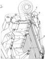
- eine Ansicht auf eine Erntemaschine mit einem Bandschneidwerk aus einer Ansicht von schräg oben,
- Fig. 2:
- eine Schnittansicht auf einen Bandschneidwerk im Bereich der Messerwinkelkonstruktion,
- Fig. 3:
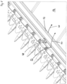
- eine Ansicht auf ein Bandschneidwerk von vorne bei demontierten Profilblechen,
- Fig. 4:
- eine Ansicht auf einen Ausschnitt eines Bandschneidwerks von unten,
- Fig. 5:
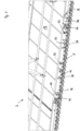
- eine Ausschnittsansicht auf ein Bandschneidwerk mit eingesetztem Winkelprofilblech, und
- Fig. 6:
- eine Schnittansicht auf das Bandschneidwerk zur Darstellung der Luftführung.
- In
Fig. 1 ist eine Ansicht auf eine Erntemaschine 4 mit einem Bandschneidwerk 2 aus einer Ansicht von schräg oben gezeigt. Das Bandschneidwerk 2 hat einen Rahmen 6, der die Gesamtkonstruktion trägt. Am vorderen Ende des Bandschneidwerks 2 befindet sich ein Messerbalken 8, mit dem das Erntegut geschnitten wird. Der Messerbalken 8 ist an einer Messerwinkelkonstruktion 10 befestigt, die näher in Figur 2 dargestellt ist. Das geschnittene Erntegut wird auf die Bandfördervorrichtungen 12 abgeworfen und von diesen zunächst mittig zusammengetragen, wonach es dann nach hinten an die Erntemaschine 4 abgegeben wird. Unterhalb des oberen Trums der Bandfördervorrichtungen 12 befindet sich eine Abstützvorrichtung 14, die inFigur 1 allerdings nicht gezeigt ist. - Die
Fig. 2 zeigt eine Schnittansicht auf einen Bandschneidwerk 2 im Bereich der Messerwinkelkonstruktion 10. Die Umrüstungsschnittstelle 18 befindet sich im Bereich der Messerwinkelkonstruktion 10. In dem Einbauraum 20 befindet sich in dem inFigur 2 gezeigten Ausführungsbeispiel ein Abdeckprofilblech 26, dass an Verbindungspunkten 22 mit der Messerwinkelkonstruktion 10 über Verschraubungen lösbar verbunden ist. Das Abdeckprofilblech 26 begrenzt nach vorne und oben einen Hohlraum 24. Das Abdeckprofilblech 26 ist nach vorne und oben hin geschlossen. Nach hinten wird der Hohlraum 24 von der Stirnwand 32 des Querträgers 28 begrenzt, der an einem Tragarm 30 gehalten ist. Der Tragarm 30 ist an seinem hinteren Ende mit dem Rahmen 6 verbunden. - Die Stirnwand 32 des Querträgers 28 weist mit ihrer Flachseite in Arbeitsrichtung des Bandschneidwerks 2. Die Stirnwand 32 ist an ihrem oberen Ende entgegen der Arbeitsrichtung des Bandschneidwerks 2 umgekantet und mit dem so ausgebildeten Schenkel so weit nach hinten geführt, dass dieser Schenkel den vorderen Rand 34 des oberen Trums der hinter der Stirnwand 32 umlaufenden Bandfördervorrichtung 12 übergreift.
- An der Frontseite der Stirnwand 32 ist eine Montageplatte 36 befestigt, die sich in einer zumindest annähernd horizontalen Richtung erstreckt und an deren vorderem Ende der Messerbalken 8 befestigt ist. Nach unten hin ist der Hohlraum 24 von der Montageplatte 36 begrenzt. Der Einbauraum 20 befindet sich im Bereich zwischen der Oberseite der Montageplatte 36 und der Stirnwand 32. In diesem Bereich ist das Abdeckprofilblech 26 auf die Messerwinkelkonstruktion 10 aufgesetzt und deckt mit seinen Schenkeln den unter dem Abdeckprofilblech 26 befindlichen Hohlraum 24 ab.
- Im Ausführungsbeispiel ist das Abdeckprofilblech 26 so ausgeführt, dass es in seiner Montageposition mit seinem oberen hinteren Ende die obere Kante 46 der Stirnwand 32 und bereichsweise auch noch den Schenkel des Querträgers 28 übergreift. Der Hohlraum 24 setzt sich auf diese Weise bis in den Spalt hinein fort, der zwischen dem oberen hinteren Ende des Abdeckprofilblechs 26 und dem gegenüberliegenden Schenkel des Querträgers 28 ausgebildet ist. Das Abdeckprofilblech 26 bildet in diesem Bereich eine erhöhte Schwelle zum unteren Rand der Bandfördervorrichtung 12 aus, die dazu dient, auf der Bandfördervorrichtung 12 befindliches Erntegut passiv davon abzuhalten, von der Bandförderervorrichtung 12 wieder auf den Ackerboden zu fallen.
- Das Abdeckprofilblech 26 weist auf seiner in Arbeitsrichtung weisenden Seite eine Sicke 48 auf, die sich über die Länge des Abdeckprofilblechs 26 erstreckt und deren Boden in der Montageposition des Abdeckprofilblechs 26 tiefer liegt als ein in Arbeitsrichtung benachbarter Abschnitt des Abdeckprofilblechs 26. die Sicke 48 dient dem Zweck, Körner und Ähren aufzufangen, die sonst auf den Ackerboden fallen würden.
- Die Stirnwand 32 des Querträgers 28 weist einige Mündungsöffnungen 38 auf, in die Längsrohre 40 eingesteckt sind. Die Längsrohre 40 dienen als Abstützung für die Abstützvorrichtung 14. Die Abstützvorrichtung 14 kann aus einer Profilleiste bestehen, deren Flachseite nach oben liegt und auf der das obere Trum der Bandfördervorrichtung 12 abgestützt umläuft. Die seitlichen Schenkel der Profilleiste der Abstützvorrichtung 14 weisen Ausschnitte auf, die zur Querschnittsform der Längsrohre 40 passen. Mit den Ausschnitten ist die Profilleiste auf die Längsrohre 40 aufgelegt, sie wird dadurch formschlüssig in ihrer Einbaulage gehalten. Wenn abweichend von der in
Figur 2 dargestellten Ausführung anstelle des Abdeckprofils 26 das Winkelprofilblech 50 in dem Einbauraum 20 montiert ist, können die Längsrohre 40 dazu genutzt werden, einen Luftstrom 60 von einem im hinteren Bereich des Bandschneidwerks 2 angeordneten Gebläse durch die Mündungsöffnung 38 hindurch in den Hohlraum 24 zu leiten. - Das Abdeckprofilblech 26 ist mit seinem vorderen unteren Ende 42 dichtend auf der Oberseite der Montageplatte 36 aufliegend gehalten. Auf diese Weise kann vom Messerbalken 8 her keinen Schmutz in den Hohlraum 24 eindringen. Wenn der Hohlraum 24 mit einem anstelle des Abdeckprofilblechs 26 montierten Winkelprofilblechs 50 als ein Luftkanal genutzt wird, kann aus dem Hohlraum 24 auch keine Luft in Richtung des Messerbalkens 8 ausströmen.
- In
Fig. 3 ist eine Ansicht auf ein Bandschneidwerk 2 von vorne bei demontierten Profilblechen 26, 50 gezeigt. Die Stirnwand 32 und die Montageplatte 36 sind gut erkennbar, die mit ihren Oberflächen den Hohlraum 24 nach unten und nach hinten begrenzen. InFigur 3 sind auch die Abdichtkörper 44 zu sehen, auf die ein Abdeckprofilblech 26 oder ein Winkelprofilblech 50 aufgelegt werden können. Der von den Profilen nach oben und vorne abgedichtete Hohlraum 24 ist dann in Querrichtung durch die Abdichtkörper 44 begrenzt, sodass dort der Luftstrom 60 nicht aus dem Hohlraum 24 austreten und von dort aus auch keinen Schmutz in diesen eindringen kann. - In
Fig. 4 ist eine Ansicht auf einen Ausschnitt eines Bandschneidwerks 2 von unten gezeigt. In der Ansicht von unten sind die Abstützvorrichtung 14, die Tragarme 30, die Längsrohre 40 sowie der Messerbalken 8 mit der Messerwinkelkonstruktion 10 gut erkennbar. Im hinteren Bereich des Bandschneidwerks 2 befindet sich ein Gebläse, dass einen Luftstrom 60 erzeugt, der über ein quer zur Arbeitsrichtung des Bandschneidwerks ausgerichtetes Verteilerrohr in die Längsrohre 40 gelangt und von diesen nach vorne bis in den Hohlraum 24 geleitet wird. - Die
Fig. 5 zeigt eine Ausschnittsansicht auf ein Bandschneidwerk 2 mit einem eingesetztem Winkelprofilblech 50. Das Winkelprofilblech 50 verfügt über eine größere Anzahl von Luftaustrittsöffnungen 52. Eine erste Reihe von Luftaustrittsöffnungen 52 befinden sich in der Sicke 48. Diese Luftaustrittsöffnungen 52 können aus dem Winkelprofilblech 50 ausgestanzt oder ausgelasert sein. Ein Luftstrom 60, der durch die Längsrohre 40 in den Hohlraum 24 gelangt, kann durch diese Luftaustrittsöffnungen 52 nach außen treten. Der Hohlraum 24 verteilt den Luftstrom 60 in Querrichtung und dient als Luftkanal, um die Luft den Luftaustrittsöffnungen 52 zuzuleiten. - Weitere Luftaustrittsöffnungen 52 befinden sich an der Hinterkante des Winkelprofilblechs 50. Hier genügt es, dass die Hinterkante des Winkelprofilblechs 50 ungerade ausgeschnitten ist. Einen Teil der dort ausgebildeten Luftaustrittsöffnungen 52 wird von dem nach hinten umgekanteten Schenkel des Querträgers 28 begrenzt.
- Die Luftaustrittsöffnungen 52 sind so angeordnet und ausgebildet, dass sie einen aus dem Luftkanal durch die Luftaustrittsöffnungen 52 austretenden Luftstrom 60 in Richtung der nach oben weisenden Oberfläche der Bandfördervorrichtungen 12, in einen darüber befindlichen Raum und/oder in eine Richtung nach oben richten.
- Das Winkelprofilblech 50 weist auf seiner in Arbeitsrichtung weisenden Seite eine Sicke 48 auf, die sich über die Länge des Winkelprofilblechs 50 erstreckt und deren Boden in der Montageposition des Winkelprofilblechs 50 tiefer liegt als ein in Arbeitsrichtung benachbarter Abschnitt des Winkelprofilblechs 50.
- Bei einem Vergleich der
Figuren 2 und5 ist erkennbar, dass in beiden Abbildungen in den Einbauraum 20 jeweils ein Profilblech eingesetzt ist, und zwar im Fall der Figur 2 das Abdeckprofilblech 26 und im Fall derFigur 5 das Winkelprofilblech 50. Während das Abdeckprofilblech 26 geschlossen ist und auf diese Weise den Hohlraum 24 nach vorne und oben vollständig abdeckt, verfügt das Winkelprofilblech 50 über Luftaustrittsöffnungen 52, durch die jeweils ein Luftstrom 60 in Richtung der Bandfördervorrichtung 12 austreten kann. In beiden Fällen ist die Umrüstungsschnittstelle 18 dazu genutzt worden, den Bereich der Messerwinkelkonstruktion 10 im Bereich des Übergangs vom Messerbalken 8 zur Bandförderervorrichtung 12 abzudecken. Je nachdem, ob als Profilblech das Abdeckprofilblech 26 oder das Winkelprofilblech 50 verwendet ist, verfügt das Bandschneidwerk 2 über eine bloße Abdeckung in diesem Bereich, oder es ist mit einem aktiven Gebläse ausgestattet, mit dem Erntegut in Richtung der Bandförderervorrichtung 12 geblasen werden kann. - In
Fig. 6 ist eine Schnittansicht auf das Bandschneidwerk 2 zur Darstellung der Luftführung gezeigt. Der Luftstrom 60 strömt aus dem Verteilerrohr über einen Anschlussstutzen 54 in das Längsrohr 40. Am vorderen Ende des Längsrohres 40 verteilt sich der Luftstrom 60 im Hohlraum 24 als Luftkanal und strömt von dort aus durch die Luftaustrittsöffnungen 52 in Richtung der Bandförderervorrichtung 12. - Die Erfindung ist nicht auf die vorstehenden Ausführungsbeispiele beschränkt. Dem Fachmann bereitet es keine Schwierigkeiten, die Ausführungsbeispiele auf eine ihm geeignet erscheinende Weise abzuwandeln, um sie an einen konkreten Anwendungsfall anzupassen.
-
- 2
- Bandschneidwerk
- 4
- Erntemaschine
- 6
- Rahmen
- 8
- Messerbalken
- 10
- Messerwinkelkonstruktion
- 12
- Bandfördervorrichtung
- 14
- Abstützvorrichtung
- 16
- Antriebsvorrichtung
- 18
- Umrüstungsschnittstelle
- 20
- Einbauraum
- 22
- Verbindungspunkt
- 24
- Hohlraum
- 26
- Abdeckprofilblech
- 28
- Querträger
- 30
- Tragarm
- 32
- Stirnwand
- 34
- Rand
- 36
- Montageplatte
- 38
- Mündungsöffnung
- 40
- Längsrohr
- 42
- vorderes unteres Ende
- 44
- Abdichtkörper
- 46
- Kante
- 48
- Sicke
- 50
- Winkelprofilblech
- 52
- Luftaustrittsöffnung
- 54
- Anschlussstutzen
- 56
- Gleitleiste
- 58
- Formstück
- 60
- Luftstrom
Claims (8)
- Bandschneidwerk (2) zum Anbau an eine Erntemaschine (4) mit einem Rahmen (6), einem Messerbalken (8), einer Messerwinkelkonstruktion (10) zur Halterung des Messerbalkens (8), Bandfördervorrichtungen (12) zum Abfördern des geschnittenen Halmguts mit einer Abstützvorrichtung (14) und Antriebsvorrichtungen (16) zum Antrieb des Messerbalkens (8) und der Bandfördervorrichtungen (12), dadurch gekennzeichnet, dass oberhalb der Messerwinkelkonstruktion (10) eine Umrüstungsschnittstelle (18) ausgebildet ist, in der in einen dafür vorgesehenen Einbauraum (20) über identische Verbindungspunkte (22) wahlweise ein Winkelprofilblech (50) oder ein Abdeckprofilblech (26) lösbar einbaubar sind, wobei sich unterhalb des Winkelprofilblechs (50) und des Abdeckprofilblechs (26) ein Hohlraum (24) befindet, der bei Verwendung des Winkelprofilblechs (50) als Luftkanal dient, das Winkelprofilblech (50) Luftaustrittsöffnungen (52) umgrenzt, die so angeordnet und ausgebildet sind, dass sie einen aus dem Luftkanal durch die Luftaustrittsöffnungen (52) austretenden Luftstrom (60) in Richtung der nach oben weisenden Oberfläche der Bandfördervorrichtungen (12), in einen darüber befindlichen Raum und/oder in eine Richtung nach oben richten, und das Abdeckprofilblech (26) so ausgestaltet ist, dass es den Hohlraum (24) geschlossen abdeckt.
- Bandschneidwerk (2) nach Anspruch 1, dadurch gekennzeichnet, dass die Messerwinkelkonstruktion (10) einen Querträger (28) aufweist, der mit zumindest einem mit dem Rahmen (6) verbundenen Tragarm (30) verbunden ist, der Querträger (28) eine mit ihrer Flachseite in Arbeitsrichtung des Bandschneidwerks (2) weisende Stirnwand (32) aufweist, die an ihrem oberen Ende entgegen der Arbeitsrichtung des Bandschneidwerks (2) umgekantet und so weit nach hinten geführt ist, dass sie den vorderen Rand (34) des oberen Trums der hinter der Stirnwand (32) umlaufenden Bandfördervorrichtung (12) übergreift, an der Frontseite der Stirnwand (32) eine Montageplatte (36) befestigt ist, die sich in einer zumindest annähernd horizontalen Richtung erstreckt und an derem vorderen Ende der Messerbalken (8) befestigt ist, die Stirnwand (32) zumindest eine Mündungsöffnung (38) aufweist, in die ein Längsrohr (40) eingesteckt ist, das sich vom hinteren Rahmen (6) bis zur Stirnwand (32) erstreckt, die Mündungsöffnung (38) oberhalb der Montageplatte (36) in der Stirnwand (32) ausgebildet ist und die oberhalb der Montageplatte (36) befindliche Stirnwand (32) und die nach oben weisende Seite der Montageplatte (36) räumlich den Bereich der Umrüstungsschnittstelle (18) begrenzen.
- Bandschneidwerk (2) nach Anspruch 1 oder 2, dadurch gekennzeichnet, dass das Winkelprofilblech (50) und das Abdeckprofilblech (26) in ihrer jeweiligen Montageposition über die Verbindungspunkte (22) mit ihrem vorderen unteren Ende (42) in einem Bereich zwischen dem hinteren Ende des Messerbalkens (8) und der Stirnwand (32) dichtend auf der Oberseite der Montageplatte (36) aufliegend gehalten sind und sich von dort bis zumindest annähernd in die maximale Höhe der Stirnwand (32) und in Längsrichtung entgegen der Arbeitsrichtung des Bandschneidwerks (2) gesehen bis zumindest annähernd an die Stirnwand (32) heran erstrecken oder diese überlappen.
- Bandschneidwerk (2) nach einem der vorhergehenden Ansprüche, dadurch gekennzeichnet, dass das Winkelprofilblech (50) in seiner Montageposition den Hohlraum (24) in Arbeitsrichtung geschlossen umgrenzt, der Hohlraum (24) an seinen stirnseitigen Enden mit den Querschnitt des Winkelprofilblechs (50) an dessen stirnseitigen Enden abdeckenden Abdichtkörpern (44) nach außen abgedichtet ist und der Hohlraum (24) nach unten und hinten zumindest bereichsweise durch die Stirnwand (32) und die Montageplatte (36) umgrenzt ist.
- Bandschneidwerk (2) nach Anspruch 3 und 4, dadurch gekennzeichnet, dass das Winkelprofilblech (50) in seiner Montageposition mit seinem hinteren Ende die obere Kante (46) der Stirnwand (32) übergreift und in dem die Stirnwand (32) übergreifenden Abschnitt Luftaustrittsöffnungen (52) ausgebildet sind.
- Bandschneidwerk (2) nach einem der vorhergehenden Ansprüche, dadurch gekennzeichnet, dass das Winkelprofilblech (50) auf seiner in Arbeitsrichtung weisenden Seite eine Sicke (48) aufweist, die sich über die Länge des Winkelprofilblechs (50) erstreckt und deren Boden in der Montageposition des Winkelprofilblechs (50) tiefer liegt als ein in Arbeitsrichtung benachbarter Abschnitt des Winkelprofilblechs (50).
- Bandschneidwerk (2) nach Anspruch 6, dadurch gekennzeichnet, dass Verbindungspunkte (22) im Bereich der Sicke (48) in der Weise ausgeführt sind, das ein Klemmstück auf einen ortsfest montierten Bolzen aufgesteckt und mit einer Spannschraube von außen auf das Abdeckprofilblech (26) oder das Winkelprofilblech (50) aufgespannt ist, wobei das Klemmstück in seiner Umfangskontur an die Raumform der Sicke angepasst ist.
- Bandschneidwerk (2) nach einem der vorhergehenden Ansprüche 2 bis 7, dadurch gekennzeichnet, dass die Längsrohre (40) Anschlussstutzen (54) aufweisen, durch die ein von einem Gebläse erzeugten Luftstrom (60) in den Innenraum der Längsrohre (40) eingeleitet werden kann, und die Längsrohre (40) dadurch ein Bestandteil des Luftfördersystem sind, indem sie den eingeleiteten Luftstrom (60) durch ihren Innenraum hindurch bis in den Bereich der Mündungsöffnung (38) in der Messerwinkelkonstruktion (10) leiten, und die Längsrohre (40) gleichzeitig einen Bestandteil der Abstützvorrichtung (14) zur Abstützung der Bandfördervorrichtung (12) bilden, indem auf die Längsrohre (40) Gleitleisten (56) aufgelegt sind, die sich in einer Richtung quer zur Arbeitsrichtung des Bandschneidwerks (2) erstrecken und über die das obere Trum der Bandfördervorrichtung (12) bei ihrem Umlauf gleitet.
Applications Claiming Priority (1)
| Application Number | Priority Date | Filing Date | Title |
|---|---|---|---|
| DE102021126683.1A DE102021126683A1 (de) | 2021-10-14 | 2021-10-14 | Bandschneidwerk mit Umrüstungsschnittstelle auf ein Luftfördersystem |
Publications (3)
| Publication Number | Publication Date |
|---|---|
| EP4165979A1 true EP4165979A1 (de) | 2023-04-19 |
| EP4165979C0 EP4165979C0 (de) | 2026-01-07 |
| EP4165979B1 EP4165979B1 (de) | 2026-01-07 |
Family
ID=83691226
Family Applications (1)
| Application Number | Title | Priority Date | Filing Date |
|---|---|---|---|
| EP22201138.9A Active EP4165979B1 (de) | 2021-10-14 | 2022-10-12 | Bandschneidwerk mit umrüstungsschnittstelle auf ein luftfördersystem |
Country Status (6)
| Country | Link |
|---|---|
| US (1) | US12514161B2 (de) |
| EP (1) | EP4165979B1 (de) |
| BR (1) | BR102022020738A2 (de) |
| CA (1) | CA3178983A1 (de) |
| DE (1) | DE102021126683A1 (de) |
| PL (1) | PL4165979T3 (de) |
Citations (6)
| Publication number | Priority date | Publication date | Assignee | Title |
|---|---|---|---|---|
| US20090199529A1 (en) * | 2008-02-11 | 2009-08-13 | Schroeder Jay D | Sickle guard with integral streamlined air discharge system for blowing plant material toward a header of an agricultural plant cutting machine |
| DE102014009159A1 (de) * | 2014-06-25 | 2015-12-31 | Carl Geringhoff Gmbh & Co. Kg | Schneidwerk mit Eingangsgetriebe |
| DE102015110746A1 (de) | 2015-07-03 | 2017-01-05 | Carl Geringhoff Gmbh & Co. Kg | Schneidwerk mit Bandfördervorrichtung und Luftaustrittsöffnungen |
| US20170295722A1 (en) * | 2016-04-18 | 2017-10-19 | Monte Busser | Crop Loss Inhibiting Device |
| DE102017113775A1 (de) | 2017-06-21 | 2018-12-27 | Carl Geringhoff Gmbh & Co. Kg | Draper-Schneidwerk mit mehrteiliger Förderschnecke |
| US20210204479A1 (en) * | 2020-01-06 | 2021-07-08 | Deere & Company | Grain loss prevention system using air blowers |
Family Cites Families (19)
| Publication number | Priority date | Publication date | Assignee | Title |
|---|---|---|---|---|
| US2734331A (en) * | 1956-02-14 | M phillips | ||
| US859602A (en) * | 1905-09-08 | 1907-07-09 | George I Green | Pneumatic attachment for sickles. |
| US1917604A (en) * | 1931-04-30 | 1933-07-11 | Avery Power Machinery Co | Sickle guard and shield |
| US2670586A (en) * | 1951-11-07 | 1954-03-02 | Julius J Wuerthner | Pneumatic attachment for grain harvesting machines |
| US2737006A (en) * | 1954-02-26 | 1956-03-06 | Jerome J Klingler | Air-conveying attachment for seed crop harvesters and the like |
| US2718744A (en) * | 1954-08-23 | 1955-09-27 | Curt M Phillips | Cutter assembly with pneumatic conveying attachment |
| US2832187A (en) * | 1956-12-28 | 1958-04-29 | Johnson John | Conveyor attachment for harvester platforms |
| US3165874A (en) * | 1963-01-07 | 1965-01-19 | Emmett H Osteen | Blower for combines |
| US3555790A (en) * | 1968-08-05 | 1971-01-19 | Univ Iowa State Res Found | Aerodynamic grain handling system |
| DE2808243A1 (de) * | 1978-02-25 | 1979-08-30 | Claas Maschf Gmbh Geb | Maehdrescherschneidwerk |
| US4783951A (en) * | 1984-10-04 | 1988-11-15 | Lloyd Richards | Pneumatic finger attachment for header unit |
| US4866919A (en) * | 1985-11-11 | 1989-09-19 | Harvestaire Pty Ltd. | Air assisted harvesting means |
| US4936082A (en) * | 1988-11-17 | 1990-06-26 | Crary Company | Mechanical air reel |
| DE4240319A1 (de) * | 1992-12-01 | 1994-06-09 | Hendlmeier Konrad | Pneumatischer Erntegutanheber vor Schneid- und Aufsammelorganen |
| US7412816B2 (en) * | 2006-03-02 | 2008-08-19 | Deere & Company | Sectionalized belt guide for draper belt in an agricultural harvesting machine |
| US7591127B1 (en) * | 2006-09-20 | 2009-09-22 | Stacer Daryl J | Grain harvester header with air assist |
| US8322520B2 (en) * | 2010-08-17 | 2012-12-04 | Deere & Company | Tongue-in-groove belt hold down for a draper platform |
| US9480203B2 (en) * | 2014-06-18 | 2016-11-01 | Crary Industries, Inc. | Harvester feed housing cleaning with pressurized fluid |
| US9591802B2 (en) * | 2015-04-28 | 2017-03-14 | Jose Luis Allochis | Belt sealing crop deflector for a flexible draper platform |
-
2021
- 2021-10-14 DE DE102021126683.1A patent/DE102021126683A1/de active Pending
-
2022
- 2022-10-12 EP EP22201138.9A patent/EP4165979B1/de active Active
- 2022-10-12 PL PL22201138.9T patent/PL4165979T3/pl unknown
- 2022-10-13 CA CA3178983A patent/CA3178983A1/en active Pending
- 2022-10-13 BR BR102022020738-0A patent/BR102022020738A2/pt unknown
- 2022-10-14 US US17/965,811 patent/US12514161B2/en active Active
Patent Citations (6)
| Publication number | Priority date | Publication date | Assignee | Title |
|---|---|---|---|---|
| US20090199529A1 (en) * | 2008-02-11 | 2009-08-13 | Schroeder Jay D | Sickle guard with integral streamlined air discharge system for blowing plant material toward a header of an agricultural plant cutting machine |
| DE102014009159A1 (de) * | 2014-06-25 | 2015-12-31 | Carl Geringhoff Gmbh & Co. Kg | Schneidwerk mit Eingangsgetriebe |
| DE102015110746A1 (de) | 2015-07-03 | 2017-01-05 | Carl Geringhoff Gmbh & Co. Kg | Schneidwerk mit Bandfördervorrichtung und Luftaustrittsöffnungen |
| US20170295722A1 (en) * | 2016-04-18 | 2017-10-19 | Monte Busser | Crop Loss Inhibiting Device |
| DE102017113775A1 (de) | 2017-06-21 | 2018-12-27 | Carl Geringhoff Gmbh & Co. Kg | Draper-Schneidwerk mit mehrteiliger Förderschnecke |
| US20210204479A1 (en) * | 2020-01-06 | 2021-07-08 | Deere & Company | Grain loss prevention system using air blowers |
Also Published As
| Publication number | Publication date |
|---|---|
| CA3178983A1 (en) | 2023-04-14 |
| PL4165979T3 (pl) | 2026-05-11 |
| BR102022020738A2 (pt) | 2023-04-25 |
| EP4165979C0 (de) | 2026-01-07 |
| US20230124269A1 (en) | 2023-04-20 |
| DE102021126683A1 (de) | 2023-04-20 |
| EP4165979B1 (de) | 2026-01-07 |
| US12514161B2 (en) | 2026-01-06 |
Similar Documents
| Publication | Publication Date | Title |
|---|---|---|
| DE102010030840B4 (de) | Schneidwerk mit verstellbarem Schneidbalken | |
| DE2736630A1 (de) | Reihen-schneidvorsatz fuer feldhaecksler | |
| EP0522268B1 (de) | Axialabscheider | |
| DE3324899A1 (de) | Gezogene oder fuer den dreipunktanbau am schlepper vorgesehene maschine zum ernten von mais od. dgl. stengelartigem erntegut | |
| EP0787425B1 (de) | Häckselmaschine und Fördervorrichtung | |
| DE2848451A1 (de) | Reihenschneid-anbaugeraet | |
| EP2915421B1 (de) | Stoppelknicker für einen maispflücker | |
| WO2017005343A1 (de) | Schneidwerk mit bandfördervorrichtung und luftaustrittsöffnungen | |
| DE102017113775A1 (de) | Draper-Schneidwerk mit mehrteiliger Förderschnecke | |
| EP0514820A1 (de) | Zinken, Halter, Zinkenbefestigungsvorrichtung und Axialabscheider | |
| EP1151654A1 (de) | Erntemaschine, insbesondere selbstfahrender Feldhäcksler | |
| DE1507195B2 (de) | Erntemaschine für stengeliges Halmgut, insbesondere Mais | |
| DE3033229A1 (de) | Erntevorrichtung fuer vorzugsweise in reihen angepflanztes erntegut mit vier foerderbahnen und einer leitvorrichtung | |
| DE19505148A1 (de) | Mähdrescher | |
| DE3908336A1 (de) | Antrieb fuer luftstroemungseinrichtung einer kaefigbatterie fuer die gefluegelhaltung | |
| EP1306003A1 (de) | Ballenpresse für landwirtschaftliches Erntegut | |
| EP4165979B1 (de) | Bandschneidwerk mit umrüstungsschnittstelle auf ein luftfördersystem | |
| DE102015206141A1 (de) | Erntevorsatz mit seitlicher Abdeckung | |
| DE2345494A1 (de) | Sammelblech-anordnung bei einem kolbenpflueck-vorsatzgeraet | |
| EP0077416B1 (de) | Zuführboden für Erntemaschinen | |
| AT391973B (de) | Erntevorrichtung fuer vorzugsweise in reihen angepflanztes erntegut | |
| DE3033299C2 (de) | Antrieb für eine Schneidvorrichtung | |
| DE102017206034A1 (de) | Maschine zur Ernte stängelartiger Pflanzen | |
| DE3324898A1 (de) | Schneid- und zufuehreinrichtung fuer eine gezogene oder fuer den dreipunktanbau am schlepper vorgesehene maschine zum ernten von mais o.dgl. stengelartigem erntegut | |
| DE2425087C2 (de) | Landwirtschaftliches Ladefahrzeug |
Legal Events
| Date | Code | Title | Description |
|---|---|---|---|
| PUAI | Public reference made under article 153(3) epc to a published international application that has entered the european phase |
Free format text: ORIGINAL CODE: 0009012 |
|
| STAA | Information on the status of an ep patent application or granted ep patent |
Free format text: STATUS: THE APPLICATION HAS BEEN PUBLISHED |
|
| AK | Designated contracting states |
Kind code of ref document: A1 Designated state(s): AL AT BE BG CH CY CZ DE DK EE ES FI FR GB GR HR HU IE IS IT LI LT LU LV MC ME MK MT NL NO PL PT RO RS SE SI SK SM TR |
|
| STAA | Information on the status of an ep patent application or granted ep patent |
Free format text: STATUS: REQUEST FOR EXAMINATION WAS MADE |
|
| 17P | Request for examination filed |
Effective date: 20230621 |
|
| RBV | Designated contracting states (corrected) |
Designated state(s): AL AT BE BG CH CY CZ DE DK EE ES FI FR GB GR HR HU IE IS IT LI LT LU LV MC ME MK MT NL NO PL PT RO RS SE SI SK SM TR |
|
| GRAP | Despatch of communication of intention to grant a patent |
Free format text: ORIGINAL CODE: EPIDOSNIGR1 |
|
| STAA | Information on the status of an ep patent application or granted ep patent |
Free format text: STATUS: GRANT OF PATENT IS INTENDED |
|
| GRAS | Grant fee paid |
Free format text: ORIGINAL CODE: EPIDOSNIGR3 |
|
| INTG | Intention to grant announced |
Effective date: 20250801 |
|
| GRAA | (expected) grant |
Free format text: ORIGINAL CODE: 0009210 |
|
| STAA | Information on the status of an ep patent application or granted ep patent |
Free format text: STATUS: THE PATENT HAS BEEN GRANTED |
|
| AK | Designated contracting states |
Kind code of ref document: B1 Designated state(s): AL AT BE BG CH CY CZ DE DK EE ES FI FR GB GR HR HU IE IS IT LI LT LU LV MC ME MK MT NL NO PL PT RO RS SE SI SK SM TR |
|
| REG | Reference to a national code |
Ref country code: CH Ref legal event code: F10 Free format text: ST27 STATUS EVENT CODE: U-0-0-F10-F00 (AS PROVIDED BY THE NATIONAL OFFICE) Effective date: 20260107 Ref country code: GB Ref legal event code: FG4D Free format text: NOT ENGLISH |
|
| REG | Reference to a national code |
Ref country code: DE Ref legal event code: R096 Ref document number: 502022006701 Country of ref document: DE |
|
| REG | Reference to a national code |
Ref country code: IE Ref legal event code: FG4D Free format text: LANGUAGE OF EP DOCUMENT: GERMAN |
|
| U01 | Request for unitary effect filed |
Effective date: 20260204 |
|
| U07 | Unitary effect registered |
Designated state(s): AT BE BG DE DK EE FI FR IT LT LU LV MT NL PT RO SE SI Effective date: 20260210 |
|
| REG | Reference to a national code |
Ref country code: HU Ref legal event code: AG4A Ref document number: E075760 Country of ref document: HU |
|
| PG25 | Lapsed in a contracting state [announced via postgrant information from national office to epo] |
Ref country code: RS Free format text: LAPSE BECAUSE OF FAILURE TO SUBMIT A TRANSLATION OF THE DESCRIPTION OR TO PAY THE FEE WITHIN THE PRESCRIBED TIME-LIMIT Effective date: 20260407 |
|
| PG25 | Lapsed in a contracting state [announced via postgrant information from national office to epo] |
Ref country code: ES Free format text: LAPSE BECAUSE OF FAILURE TO SUBMIT A TRANSLATION OF THE DESCRIPTION OR TO PAY THE FEE WITHIN THE PRESCRIBED TIME-LIMIT Effective date: 20260107 |
|
| PG25 | Lapsed in a contracting state [announced via postgrant information from national office to epo] |
Ref country code: GR Free format text: LAPSE BECAUSE OF FAILURE TO SUBMIT A TRANSLATION OF THE DESCRIPTION OR TO PAY THE FEE WITHIN THE PRESCRIBED TIME-LIMIT Effective date: 20260408 |
|
| PG25 | Lapsed in a contracting state [announced via postgrant information from national office to epo] |
Ref country code: NO Free format text: LAPSE BECAUSE OF FAILURE TO SUBMIT A TRANSLATION OF THE DESCRIPTION OR TO PAY THE FEE WITHIN THE PRESCRIBED TIME-LIMIT Effective date: 20260407 |
|
| PG25 | Lapsed in a contracting state [announced via postgrant information from national office to epo] |
Ref country code: HR Free format text: LAPSE BECAUSE OF FAILURE TO SUBMIT A TRANSLATION OF THE DESCRIPTION OR TO PAY THE FEE WITHIN THE PRESCRIBED TIME-LIMIT Effective date: 20260107 |
|
| PG25 | Lapsed in a contracting state [announced via postgrant information from national office to epo] |
Ref country code: IS Free format text: LAPSE BECAUSE OF FAILURE TO SUBMIT A TRANSLATION OF THE DESCRIPTION OR TO PAY THE FEE WITHIN THE PRESCRIBED TIME-LIMIT Effective date: 20260507 |