EP4165342B1 - Lichtmodul zur montage in einer optischen anordnung für ein kraftfahrzeug - Google Patents
Lichtmodul zur montage in einer optischen anordnung für ein kraftfahrzeug Download PDFInfo
- Publication number
- EP4165342B1 EP4165342B1 EP21732959.8A EP21732959A EP4165342B1 EP 4165342 B1 EP4165342 B1 EP 4165342B1 EP 21732959 A EP21732959 A EP 21732959A EP 4165342 B1 EP4165342 B1 EP 4165342B1
- Authority
- EP
- European Patent Office
- Prior art keywords
- optical reflector
- screen
- optical
- light module
- edge
- Prior art date
- Legal status (The legal status is an assumption and is not a legal conclusion. Google has not performed a legal analysis and makes no representation as to the accuracy of the status listed.)
- Active
Links
Images



Classifications
-
- F—MECHANICAL ENGINEERING; LIGHTING; HEATING; WEAPONS; BLASTING
- F21—LIGHTING
- F21S—NON-PORTABLE LIGHTING DEVICES; SYSTEMS THEREOF; VEHICLE LIGHTING DEVICES SPECIALLY ADAPTED FOR VEHICLE EXTERIORS
- F21S43/00—Signalling devices specially adapted for vehicle exteriors, e.g. brake lamps, direction indicator lights or reversing lights
- F21S43/20—Signalling devices specially adapted for vehicle exteriors, e.g. brake lamps, direction indicator lights or reversing lights characterised by refractors, transparent cover plates, light guides or filters
- F21S43/26—Refractors, transparent cover plates, light guides or filters not provided in groups F21S43/235 - F21S43/255
-
- F—MECHANICAL ENGINEERING; LIGHTING; HEATING; WEAPONS; BLASTING
- F21—LIGHTING
- F21S—NON-PORTABLE LIGHTING DEVICES; SYSTEMS THEREOF; VEHICLE LIGHTING DEVICES SPECIALLY ADAPTED FOR VEHICLE EXTERIORS
- F21S43/00—Signalling devices specially adapted for vehicle exteriors, e.g. brake lamps, direction indicator lights or reversing lights
- F21S43/20—Signalling devices specially adapted for vehicle exteriors, e.g. brake lamps, direction indicator lights or reversing lights characterised by refractors, transparent cover plates, light guides or filters
- F21S43/27—Attachment thereof
-
- F—MECHANICAL ENGINEERING; LIGHTING; HEATING; WEAPONS; BLASTING
- F21—LIGHTING
- F21S—NON-PORTABLE LIGHTING DEVICES; SYSTEMS THEREOF; VEHICLE LIGHTING DEVICES SPECIALLY ADAPTED FOR VEHICLE EXTERIORS
- F21S43/00—Signalling devices specially adapted for vehicle exteriors, e.g. brake lamps, direction indicator lights or reversing lights
- F21S43/50—Signalling devices specially adapted for vehicle exteriors, e.g. brake lamps, direction indicator lights or reversing lights characterised by aesthetic components not otherwise provided for, e.g. decorative trim, partition walls or covers
-
- F—MECHANICAL ENGINEERING; LIGHTING; HEATING; WEAPONS; BLASTING
- F21—LIGHTING
- F21S—NON-PORTABLE LIGHTING DEVICES; SYSTEMS THEREOF; VEHICLE LIGHTING DEVICES SPECIALLY ADAPTED FOR VEHICLE EXTERIORS
- F21S43/00—Signalling devices specially adapted for vehicle exteriors, e.g. brake lamps, direction indicator lights or reversing lights
- F21S43/50—Signalling devices specially adapted for vehicle exteriors, e.g. brake lamps, direction indicator lights or reversing lights characterised by aesthetic components not otherwise provided for, e.g. decorative trim, partition walls or covers
- F21S43/51—Attachment thereof
-
- F—MECHANICAL ENGINEERING; LIGHTING; HEATING; WEAPONS; BLASTING
- F21—LIGHTING
- F21S—NON-PORTABLE LIGHTING DEVICES; SYSTEMS THEREOF; VEHICLE LIGHTING DEVICES SPECIALLY ADAPTED FOR VEHICLE EXTERIORS
- F21S45/00—Arrangements within vehicle lighting devices specially adapted for vehicle exteriors, for purposes other than emission or distribution of light
- F21S45/20—Promoting gas flow in lighting devices, e.g. directing flow toward the cover glass for demisting
Definitions
- the present invention relates to a light module intended to be mounted in an optical unit for a motor vehicle.
- the regulations require that every motor vehicle be equipped with lighting and signalling light modules to warn road users of the position and intentions of the motor vehicle.
- a light module consists of a light source associated with its own optics, so as to allow the projection of a light beam in compliance with regulations.
- the documents CN 103 994 386 A , JP 2014 157693 A , CN 207 112 688 U describe known light modules.
- optical units In order to facilitate the installation of the light modules on a motor vehicle, they are first grouped in optical units. The optical units are then fitted into housings in the body of the motor vehicle, provided for this purpose. An optical unit thus makes it possible to install several light modules simultaneously on a motor vehicle, simply and quickly.
- an optical unit comprises an optical housing of standardized shape, to fit perfectly into a housing of the body of a motor vehicle.
- the light modules are arranged in the optical housing.
- the optical housing comprises an opening which is closed by a transparent glass, in order to allow the light modules to illuminate the environment of the motor vehicle while protecting them from bad weather and dust.
- the more attractive the visual signature the more difficult it is to guarantee a clean appearance of the signature. Indeed, the slightest leak around the screen can spoil the final rendering. This is particularly the case when the screen is partially opacified by the deposition of a metallized layer, so as to produce a distinctive light pattern when the light module is activated.
- the contours of the light pattern must be clear, particularly at its periphery. The edges of the screen must therefore remain dark when it is illuminated by the light source.
- the present invention aims to solve this technical problem, by proposing a light module comprising a screen backlit by a light source, preventing a phenomenon of condensation on the surface of the screen during operation of the light module.
- a light module according to the invention as defined in claim 1 intended to be mounted in an optical unit for a motor vehicle, comprises a light source, an optical reflector reflecting the light emitted by the light source and a screen placed in front of the optical reflector, the screen being capable of transmitting at least part of the light reflected by the optical reflector.
- the invention is remarkable in that the edge of the optical reflector opposite the screen is extended by a rim extending towards the screen, and the periphery of the screen facing the optical reflector is curved so as to extend parallel or substantially parallel to the edge of the optical reflector, and the edge of the optical reflector is kept at a distance from the screen so as to allow the passage of an air flow between the optical reflector and the screen.
- the rim of the optical reflector has a thickness smaller than the thickness of the edge of the optical reflector, so as to form a riser delimiting the edge of the rim of the optical reflector, and the height of the riser is greater than the thickness of the perimeter of the screen, and the perimeter of the screen is held opposite the riser so as not to exceed the riser;
- the riser is adjacent to an external face of the optical reflector, the external face being opposite an internal face of the optical reflector illuminated by the light source .
- the invention also relates to an optical unit for a motor vehicle, comprising an optical housing having an opening closed by a glass.
- the optical unit comprises a light module as described above and the optical reflector of the light module comprises a holding appendage, cooperating with an internal wall of the optical housing, so as to hold the optical reflector to the internal wall.
- the perimeter of the screen opposite the optical reflector comprises a notch
- the optical reflector and/or the optical housing comprises a notch opposite the notch of the optical reflector, so as to allow or promote the passage of an air flow between the internal wall of the optical housing, the optical reflector and the screen.
- the perimeter of the screen opposite the optical reflector comprises a riser resting against a wall of the optical housing.
- the invention proposes a light module comprising a screen backlit by a light source, making it possible to prevent a phenomenon of condensation on the surface of the screen of the light module during its operation.
- FIGS. 1 to 6 illustrate a non-limiting embodiment of a light module 2 according to the invention, mounted in an optical unit for a motor vehicle.
- the light module 2 comprises a light source 4 capable of emitting a light beam 6 meeting the regulatory specifications.
- the light source 4 is capable of emitting a light beam 6 of white, red or amber color.
- the internal face 10 of the optical reflector is of concave shape.
- the optical reflector is made from one of the following materials: polycarbonate, acrylonitrile butadiene styrene, poly(methyl methacrylate).
- the inner face 10 of the optical reflector is preferably covered with a metallized layer, in order to increase its reflection properties.
- the optical reflector comprises an outer face 14, connected to the inner face 10 by means of an edge 16 facing the screen 12. According to the present example, the outer face 14 is substantially parallel to the inner face 10.
- the edge 16 of the optical reflector located opposite the screen 12 is extended by a rim 18.
- the rim extends in the direction of the screen 12. According to the present example, the rim extends parallel or substantially parallel to the direction of emission of the light beam emerging from the light module 2.
- the length of the rim 18 of the optical reflector 8, defined in a direction parallel or substantially parallel to the direction of emission of the light beam 6 emitted by the light module, is between 2 mm and 20 mm, preferably between 5 mm and 15 mm.
- the thickness of the rim 18, defined in a direction normal or substantially normal to the internal face 10 of the optical reflector is between 10 mm and 40 mm, preferably between 15 mm and 25 mm.
- the light module comprises a screen 12, arranged opposite the internal face 10 of the optical reflector, so as to be backlit by the light beam 6 emitted by the light source 4.
- the screen is transparent.
- the screen 12 is made from of one of the following materials: poly(methyl methacrylate) or polycarbonate.
- the screen 12 is partially covered by a layer opaque to the light beam 6 emitted by the light source 4, such that a light pattern appears and is visible to an observer when the light module 2 is activated.
- the outline of the screen is covered by the opaque layer so as to highlight the light pattern.
- the opaque layer may be present on an internal or external face of the screen.
- the expression “internal face” denotes a face of an object directly illuminated by the light beam 6.
- the invention proposes an original solution for preserving the dark outline of the screen 12, by avoiding a phenomenon of leakage of the light beam 6 around the screen when activating the light source 4, while limiting the risk of formation of a layer of condensation on the surface of the screen 12.
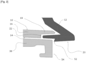
- the invention proposes an original arrangement between the optical reflector 8 and the screen 12. More precisely, as illustrated by the figure 2 , the periphery 20 of the screen located opposite the optical reflector 8 is curved so as to extend parallel or substantially parallel to the edge 18 of the optical reflector 8, and the edge 18 of the optical reflector is kept at a distance from the screen 12 so as to allow the passage of an air flow between the optical reflector 8 and the screen 12.
- this particular tile-shaped assembly between the edge 18 of the optical reflector 8 and the periphery 20 of the screen, delimits a sinuous passage in the form of a baffle so as to completely prevent the light beam 6 emitted by the light source 4 from reaching the outside of the light module 2, while allowing the circulation of an air flow between the outside and the inside of the light module 2.
- the smallest distance between the edge 18 of the optical reflector 8 and the periphery 20 of the screen opposite the optical reflector is between 0.5 mm and 10 mm, preferably between 0.5 mm and 2 mm, to promote sufficient air circulation between the inside and the outside of the light module 2 in order to prevent a condensation phenomenon on the screen 12.
- the perimeter 20 of the screen 12 is superimposed on the edge 18. of the optical reflector 8, over a distance of between 5 mm and 50 mm, preferably between 5 mm and 15 mm, in order to significantly attenuate the intensity of a light beam propagating between the screen 12 and the optical reflector 8, preferably to completely attenuate the intensity.
- the edge 18 of the optical reflector 8 has a thickness smaller than the thickness of the edge 16 of the optical reflector, so as to form a riser 22 delimiting the edge 16 of the edge 18 of the optical reflector.
- the riser 22 is perpendicular or substantially perpendicular to the internal face 10 of the optical reflector.
- the height of the riser is greater than the thickness of the perimeter 20 of the screen, so that the perimeter of the screen is maintained opposite the riser 22 without exceeding the riser.
- the riser 22 is formed so that the perimeter 20 of the screen 12 is in the extension of the external face 14 of the optical reflector 8, so as to preserve the homogeneity of the external surface of the light module 2.
- each holding appendage 24 comprises a tab 26 extending parallel to the external face 14 of the optical reflector.
- Each tab comprises an opening 28 intended to cooperate with a lug 30 present on the external face 14 of the optical reflector 8, so as to ensure the holding of the periphery 20 of the screen to the edge 16 of the optical reflector 8 by a reversible clipping technique.
- the screen 12 also includes centering appendages 32 visible on the figures 3 And 5 .
- Each centering appendage 32 consists of a tab 34 extending parallel to the external face 14 of the optical reflector.
- the free ends of the tabs 34 are narrow in shape, in the form of a “V” or a “U”, in order to be inserted more easily into dedicated housings 36 present on the external face 14 of the optical reflector.
- the light module 2 is arranged in an optical housing 38 of an optical unit 40, intended to be mounted on a motor vehicle.
- the optical housing 38 comprises an opening closed by a glass 42.
- the glass is transparent and protects the light module from bad weather. as well as external dust.
- the light module 2 is arranged so that its screen 12 is opposite the glass 42.
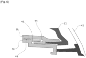
- the optical reflector 8 has at its external face 14 a retention appendage 44 visible on the figure 5 , cooperating with a dedicated housing 46 present on an internal face 48 of the optical housing 38.
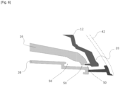
- the perimeter 20 of the screen facing the optical reflector 8 comprises one or more notches 50, and the optical reflector 8 and/or the optical housing 38 also comprises one or more notches 50 facing the notch of the optical reflector, so as to allow the passage of an air flow between the internal face 48 of the optical housing 38, the optical reflector 8 and the screen 12.
- This embodiment visible on the figure 6 promotes greater air circulation in the optical block 40.
- the notches 50 are present at the areas of the screen least illuminated by the light beam 6, for example at the corners of the screen 12.
- the perimeter 20 of the screen opposite the optical reflector 8 may comprise a riser 52 bearing against a wall 54 of the optical housing 38, so as to ensure greater support of the screen 12 against the optical housing 38.
Landscapes
- Engineering & Computer Science (AREA)
- General Engineering & Computer Science (AREA)
- Non-Portable Lighting Devices Or Systems Thereof (AREA)
Claims (8)
- / Lichtmodul (2) zum Einbau in eine Optikeinheit (40) für ein Kraftfahrzeug, bestehend aus einer Lichtquelle (4), einem das von der Lichtquelle (4) emittierten Licht reflektierenden optischen Reflektor (8) und a Schirm (12), der vor dem optischen Reflektor (8) angeordnet ist, wobei der Schirm (12) mindestens einen Teil des vom optischen Reflektor (8) reflektierten Lichts durchlassen kann, dadurch gekennzeichnet, dass der Rand (16) des optischen Reflektor (8) in gegenüber dem Schirm (12) durch einen in Richtung des Schirms (12) verlaufenden Rand (18) verlängert ist und dass der Rand (20) des Schirms (12) gegenüber dem optischen Reflektor (8) so gekrümmt ist dass sie parallel oder im Wesentlichen parallel zum Rand (18) des optischen Reflektors (8) verläuft und dass der Rand (18) des optischen Reflektors (8) in einem Abstand von der Blende (12) gehalten wird, um den Durchgang eines Luftstroms zwischen dem optischen Reflektor (8) und der Blende (12) zu ermöglichen, und dass der Rand (18) ) der Optik Der Reflektor (8) weist eine geringere Dicke als die Dicke des Randes (16) des optischen Reflektors (8) auf, so dass eine Erhebung (22) gebildet wird, die den Rand (16) des Randes (18) des Reflektors (8) begrenzt optischen Reflektor (8), und dass die Höhe der Erhöhung (22) größer ist als die Dicke des Randes (20) des Schirms (12), und dass der Rand (20) des Schirms (12) größer ist gegenüber dem Steigrohr (22) gehalten wird, so dass es nicht über das Steigrohr (22) hinausragt, und dass das Steigrohr (22) an einer Außenfläche (14) des Steigrohrs anliegt optischen Reflektor (8), wobei die Außenfläche (14) einer von der Lichtquelle (4) beleuchteten Innenfläche (10) des optischen Reflektors (8) gegenüberliegt.
- / Lichtmodul (2) nach Anspruch 1, dadurch gekennzeichnet, dass die Länge des Randes (18) des optischen Reflektors (8) in einer Richtung parallel oder im Wesentlichen parallel zur Emissionsrichtung des Lichtstrahls (6) definiert ist ), die das Lichtmodul (2) aussendet, liegt zwischen 2 mm und 20 mm.
- / Lichtmodul (2) nach Anspruch 1 oder 2, dadurch gekennzeichnet, dass der kleinste Abstand zwischen dem Rand (18) des optischen Reflektors (8) und dem Rand (20) des Schirms (12) gegenüberliegt optischer Reflektor (8), liegt zwischen 0,5 mm und 10 mm.
- / Lichtmodul (2) nach einem der Ansprüche 1 bis 3, dadurch gekennzeichnet, dass der dem optischen Reflektor (8) zugewandte Rand (20) des Schirms (12) durch mehrere Haltevorrichtungsfortsätze (24) verlängert ist, die jeweils halten Der Fortsatz kann an einer am Rand (16) des optischen Reflektors (8) vorhandenen Lasche (30) befestigt werden.
- / Lichtmodul (2) nach einem der Ansprüche 1 bis 4, dadurch gekennzeichnet, dass der dem optischen Reflektor (8) zugewandte Rand (20) des Schirms (12) durch mehrere Zentriervorrichtungsfortsätze (32) verlängert ist, die jeweils zentrieren Der Fortsatz ist zum Einsetzen in eine am Rand (16) des optischen Reflektors (8) vorhandene Aufnahme (36) ausgebildet.
- / Optikeinheit (40) für ein Kraftfahrzeug, umfassend ein Optikgehäuse (38), das eine durch ein Glas (42) verschlossene Öffnung umfasst, dadurch gekennzeichnet, dass es ein Lichtmodul (2) nach einem der Ansprüche 1 bis 5 umfasst, und dass der optische Reflektor (8) des Lichtmoduls (2) einen Haltefortsatz (44) umfasst, der mit einer Innenfläche (48) des optischen Gehäuses (38) zusammenwirkt, um so den optischen Reflektor (8) zu halten die Innenseite (48).
- / Optische Einheit (40) nach Anspruch 6, dadurch gekennzeichnet, dass der dem optischen Reflektor (8) zugewandte Rand (20) des Schirms (12) eine Kerbe (50) aufweist und dass der optische Reflektor (8) und/oder das Optikgehäuse (38) eine der Kerbe des optischen Reflektors (8) zugewandte Kerbe (50) aufweist, um den Durchgang zu ermöglichen eines Luftstroms zwischen der Innenwand des Optikgehäuses (38), dem Optikreflektor (8) und dem Schirm (12).
- / Optische Einheit (40) nach Anspruch 6 oder 7, dadurch gekennzeichnet, dass der dem optischen Reflektor (8) zugewandte Rand (20) des Schirms (12) eine an einer Wand (54) des Schirms (8) abstützende Erhebung (52) aufweist Optikgehäuse (38).
Applications Claiming Priority (2)
| Application Number | Priority Date | Filing Date | Title |
|---|---|---|---|
| FR2006293A FR3111412A1 (fr) | 2020-06-16 | 2020-06-16 | Module lumineux destiné à être monté dans un bloc optique pour véhicule automobile |
| PCT/FR2021/050797 WO2021255358A1 (fr) | 2020-06-16 | 2021-05-10 | Module lumineux destiné à être monté dans un bloc optique pour véhicule automobile |
Publications (2)
| Publication Number | Publication Date |
|---|---|
| EP4165342A1 EP4165342A1 (de) | 2023-04-19 |
| EP4165342B1 true EP4165342B1 (de) | 2025-02-26 |
Family
ID=74859951
Family Applications (1)
| Application Number | Title | Priority Date | Filing Date |
|---|---|---|---|
| EP21732959.8A Active EP4165342B1 (de) | 2020-06-16 | 2021-05-10 | Lichtmodul zur montage in einer optischen anordnung für ein kraftfahrzeug |
Country Status (4)
| Country | Link |
|---|---|
| EP (1) | EP4165342B1 (de) |
| CN (1) | CN115702311A (de) |
| FR (1) | FR3111412A1 (de) |
| WO (1) | WO2021255358A1 (de) |
Family Cites Families (12)
| Publication number | Priority date | Publication date | Assignee | Title |
|---|---|---|---|---|
| GB1259114A (de) | 1968-04-16 | 1972-01-05 | ||
| JP4166439B2 (ja) * | 2001-02-05 | 2008-10-15 | 株式会社小糸製作所 | 灯具 |
| KR101114068B1 (ko) * | 2009-12-01 | 2012-02-22 | 기아자동차주식회사 | 차량용 헤드램프 |
| CN102418906B (zh) * | 2010-09-10 | 2014-10-15 | 株式会社小糸制作所 | 光学组件 |
| CN201983151U (zh) * | 2010-12-10 | 2011-09-21 | 吴忠宪 | 车灯 |
| CN102175007B (zh) * | 2011-01-11 | 2013-01-23 | 重庆隆鑫机车有限公司 | 摩托车前大灯及其摩托车 |
| JP6096529B2 (ja) * | 2013-02-15 | 2017-03-15 | スタンレー電気株式会社 | 車両用灯具ユニット |
| US9987975B2 (en) * | 2013-11-19 | 2018-06-05 | Koito Manufacturing Co., Ltd. | Vehicle lamp with integrally formed housing, first light guiding lens, and second light guiding lens |
| CN103994386A (zh) * | 2014-05-29 | 2014-08-20 | 江苏迅驰汽车部件有限公司 | 一种汽车后尾灯 |
| DE102016205644B4 (de) * | 2016-04-06 | 2024-10-17 | Volkswagen Aktiengesellschaft | Beleuchtungsvorrichtung für ein Kraftfahrzeug |
| CN207112688U (zh) * | 2017-07-06 | 2018-03-16 | 上海小糸车灯有限公司 | 具有立体发光效果的车灯内配光镜 |
| US10838137B2 (en) * | 2017-08-29 | 2020-11-17 | Varroc Lighting Systems, s.r.o. | Lighting device with high efficiency and uniformity |
-
2020
- 2020-06-16 FR FR2006293A patent/FR3111412A1/fr not_active Withdrawn
-
2021
- 2021-05-10 WO PCT/FR2021/050797 patent/WO2021255358A1/fr not_active Ceased
- 2021-05-10 EP EP21732959.8A patent/EP4165342B1/de active Active
- 2021-05-10 CN CN202180042917.6A patent/CN115702311A/zh active Pending
Also Published As
| Publication number | Publication date |
|---|---|
| CN115702311A (zh) | 2023-02-14 |
| FR3111412A1 (fr) | 2021-12-17 |
| WO2021255358A1 (fr) | 2021-12-23 |
| EP4165342A1 (de) | 2023-04-19 |
Similar Documents
| Publication | Publication Date | Title |
|---|---|---|
| EP3390900B1 (de) | Lichteinheit, insbesondere für kfz-bremslicht | |
| EP4065882B1 (de) | Lichtmodul eines kraftfahrzeugs, das mit einem optischen element ausgestattet ist | |
| FR2526522A1 (fr) | Perfectionnements aux feux pour vehicules automobiles | |
| EP3273149A1 (de) | Leuchtmodul für kraftfahrzeuge | |
| FR3126746A1 (fr) | Dispositif lumineux d’un véhicule automobile | |
| EP3208526B1 (de) | Lichtanlage zur beleuchtung und/oder signalisierung für kraftfahrzeug | |
| EP2442016A2 (de) | Glasscheibe einer Beleuchtungs- und/oder Signalvorrichtung mit variablem Leuchtkraftübertragungskoeffizenten | |
| FR3116884A1 (fr) | Dispositif d’éclairage protégé contre les fuites de lumière. | |
| EP3158258B1 (de) | Beleuchtungs- und/oder signalisierungsvorrichtung zur erzeugung eines gleichmässigen lichts auf einem bildschirm | |
| EP4165342A1 (de) | Lichtmodul zur montage in einer optischen anordnung für ein kraftfahrzeug | |
| WO2019197761A1 (fr) | Dispositif lumineux d'apparence sombre pour véhicule automobile | |
| FR3103538A1 (fr) | Module de signalisation pour véhicules automobiles | |
| FR2815589A1 (fr) | Dispositif d'eclairage ou de signalisation pour vehicule automobile | |
| EP1862728A1 (de) | Beleuchtungs- und/oder Signalvorrichtungen für Fahrzeuge mit einer metallisierten Abdeckscheibe | |
| EP1813860B1 (de) | Verdunklungselement des Reflektors eines Scheinwerfers und Verfahren zur Montage eines solchen Elementes | |
| EP0229572B1 (de) | Signalleuchte mit farbiger Beleuchtung, insbesondere für Kraftfahrzeuge | |
| FR2937118A1 (fr) | Dispositif d'eclairage et/ou de signalisation pour vehicule automobile. | |
| FR2675093A1 (fr) | Bloc optique a enjoliveur perfectionne, notamment pour vehicule automobile. | |
| EP1585658A1 (de) | Erfassungsvorrichtung mit mitteln zur reinigung einesdurchsichtigen fensters | |
| EP4226078B1 (de) | Doppelfensterscheinwerfer und fahrzeug mit einem solchen scheinwerfer | |
| FR3070334A1 (fr) | Piece de carrosserie comportant une surface metallisee formant enjoliveur et reflecteur de lumiere | |
| FR3167105A1 (fr) | Element de garnissage comprenant un logo rétroéclairé et un radar | |
| FR2648541A1 (fr) | Projecteur a faisceau coupe, notamment projecteur de croisement, ameliorant l'eclairement des panneaux de signalisation routiere | |
| EP0806604A1 (de) | Kfz-Signalleuchte mit Mitteln zur Begrenzung des Beleuchtungsfeldes | |
| FR3144854A1 (fr) | Dispositif d’éclairage et/ou de signalisation pour véhicule avec effet miroir à l’infini. |
Legal Events
| Date | Code | Title | Description |
|---|---|---|---|
| STAA | Information on the status of an ep patent application or granted ep patent |
Free format text: STATUS: UNKNOWN |
|
| STAA | Information on the status of an ep patent application or granted ep patent |
Free format text: STATUS: THE INTERNATIONAL PUBLICATION HAS BEEN MADE |
|
| PUAI | Public reference made under article 153(3) epc to a published international application that has entered the european phase |
Free format text: ORIGINAL CODE: 0009012 |
|
| STAA | Information on the status of an ep patent application or granted ep patent |
Free format text: STATUS: REQUEST FOR EXAMINATION WAS MADE |
|
| 17P | Request for examination filed |
Effective date: 20221121 |
|
| AK | Designated contracting states |
Kind code of ref document: A1 Designated state(s): AL AT BE BG CH CY CZ DE DK EE ES FI FR GB GR HR HU IE IS IT LI LT LU LV MC MK MT NL NO PL PT RO RS SE SI SK SM TR |
|
| DAV | Request for validation of the european patent (deleted) | ||
| DAX | Request for extension of the european patent (deleted) | ||
| RAP3 | Party data changed (applicant data changed or rights of an application transferred) |
Owner name: STELLANTIS AUTO SAS |
|
| GRAP | Despatch of communication of intention to grant a patent |
Free format text: ORIGINAL CODE: EPIDOSNIGR1 |
|
| STAA | Information on the status of an ep patent application or granted ep patent |
Free format text: STATUS: GRANT OF PATENT IS INTENDED |
|
| INTG | Intention to grant announced |
Effective date: 20241010 |
|
| GRAS | Grant fee paid |
Free format text: ORIGINAL CODE: EPIDOSNIGR3 |
|
| GRAA | (expected) grant |
Free format text: ORIGINAL CODE: 0009210 |
|
| STAA | Information on the status of an ep patent application or granted ep patent |
Free format text: STATUS: THE PATENT HAS BEEN GRANTED |
|
| AK | Designated contracting states |
Kind code of ref document: B1 Designated state(s): AL AT BE BG CH CY CZ DE DK EE ES FI FR GB GR HR HU IE IS IT LI LT LU LV MC MK MT NL NO PL PT RO RS SE SI SK SM TR |
|
| REG | Reference to a national code |
Ref country code: GB Ref legal event code: FG4D Free format text: NOT ENGLISH |
|
| REG | Reference to a national code |
Ref country code: CH Ref legal event code: EP |
|
| REG | Reference to a national code |
Ref country code: DE Ref legal event code: R096 Ref document number: 602021026790 Country of ref document: DE |
|
| REG | Reference to a national code |
Ref country code: DE Ref legal event code: R084 Ref document number: 602021026790 Country of ref document: DE Ref country code: IE Ref legal event code: FG4D Free format text: LANGUAGE OF EP DOCUMENT: FRENCH |
|
| REG | Reference to a national code |
Ref country code: NL Ref legal event code: MP Effective date: 20250226 |
|
| PG25 | Lapsed in a contracting state [announced via postgrant information from national office to epo] |
Ref country code: RS Free format text: LAPSE BECAUSE OF FAILURE TO SUBMIT A TRANSLATION OF THE DESCRIPTION OR TO PAY THE FEE WITHIN THE PRESCRIBED TIME-LIMIT Effective date: 20250526 |
|
| PG25 | Lapsed in a contracting state [announced via postgrant information from national office to epo] |
Ref country code: FI Free format text: LAPSE BECAUSE OF FAILURE TO SUBMIT A TRANSLATION OF THE DESCRIPTION OR TO PAY THE FEE WITHIN THE PRESCRIBED TIME-LIMIT Effective date: 20250226 |
|
| PG25 | Lapsed in a contracting state [announced via postgrant information from national office to epo] |
Ref country code: PL Free format text: LAPSE BECAUSE OF FAILURE TO SUBMIT A TRANSLATION OF THE DESCRIPTION OR TO PAY THE FEE WITHIN THE PRESCRIBED TIME-LIMIT Effective date: 20250226 |
|
| PGFP | Annual fee paid to national office [announced via postgrant information from national office to epo] |
Ref country code: DE Payment date: 20250423 Year of fee payment: 5 |
|
| PG25 | Lapsed in a contracting state [announced via postgrant information from national office to epo] |
Ref country code: ES Free format text: LAPSE BECAUSE OF FAILURE TO SUBMIT A TRANSLATION OF THE DESCRIPTION OR TO PAY THE FEE WITHIN THE PRESCRIBED TIME-LIMIT Effective date: 20250226 |
|
| REG | Reference to a national code |
Ref country code: LT Ref legal event code: MG9D |
|
| PG25 | Lapsed in a contracting state [announced via postgrant information from national office to epo] |
Ref country code: NO Free format text: LAPSE BECAUSE OF FAILURE TO SUBMIT A TRANSLATION OF THE DESCRIPTION OR TO PAY THE FEE WITHIN THE PRESCRIBED TIME-LIMIT Effective date: 20250526 Ref country code: IS Free format text: LAPSE BECAUSE OF FAILURE TO SUBMIT A TRANSLATION OF THE DESCRIPTION OR TO PAY THE FEE WITHIN THE PRESCRIBED TIME-LIMIT Effective date: 20250626 |
|
| PG25 | Lapsed in a contracting state [announced via postgrant information from national office to epo] |
Ref country code: NL Free format text: LAPSE BECAUSE OF FAILURE TO SUBMIT A TRANSLATION OF THE DESCRIPTION OR TO PAY THE FEE WITHIN THE PRESCRIBED TIME-LIMIT Effective date: 20250226 |
|
| PG25 | Lapsed in a contracting state [announced via postgrant information from national office to epo] |
Ref country code: HR Free format text: LAPSE BECAUSE OF FAILURE TO SUBMIT A TRANSLATION OF THE DESCRIPTION OR TO PAY THE FEE WITHIN THE PRESCRIBED TIME-LIMIT Effective date: 20250226 |
|
| PG25 | Lapsed in a contracting state [announced via postgrant information from national office to epo] |
Ref country code: PT Free format text: LAPSE BECAUSE OF FAILURE TO SUBMIT A TRANSLATION OF THE DESCRIPTION OR TO PAY THE FEE WITHIN THE PRESCRIBED TIME-LIMIT Effective date: 20250626 Ref country code: LV Free format text: LAPSE BECAUSE OF FAILURE TO SUBMIT A TRANSLATION OF THE DESCRIPTION OR TO PAY THE FEE WITHIN THE PRESCRIBED TIME-LIMIT Effective date: 20250226 |
|
| PGFP | Annual fee paid to national office [announced via postgrant information from national office to epo] |
Ref country code: FR Payment date: 20250423 Year of fee payment: 5 |
|
| PG25 | Lapsed in a contracting state [announced via postgrant information from national office to epo] |
Ref country code: GR Free format text: LAPSE BECAUSE OF FAILURE TO SUBMIT A TRANSLATION OF THE DESCRIPTION OR TO PAY THE FEE WITHIN THE PRESCRIBED TIME-LIMIT Effective date: 20250527 Ref country code: BG Free format text: LAPSE BECAUSE OF FAILURE TO SUBMIT A TRANSLATION OF THE DESCRIPTION OR TO PAY THE FEE WITHIN THE PRESCRIBED TIME-LIMIT Effective date: 20250226 |
|
| REG | Reference to a national code |
Ref country code: AT Ref legal event code: MK05 Ref document number: 1770946 Country of ref document: AT Kind code of ref document: T Effective date: 20250226 |
|
| PG25 | Lapsed in a contracting state [announced via postgrant information from national office to epo] |
Ref country code: SE Free format text: LAPSE BECAUSE OF FAILURE TO SUBMIT A TRANSLATION OF THE DESCRIPTION OR TO PAY THE FEE WITHIN THE PRESCRIBED TIME-LIMIT Effective date: 20250226 |
|
| PG25 | Lapsed in a contracting state [announced via postgrant information from national office to epo] |
Ref country code: SM Free format text: LAPSE BECAUSE OF FAILURE TO SUBMIT A TRANSLATION OF THE DESCRIPTION OR TO PAY THE FEE WITHIN THE PRESCRIBED TIME-LIMIT Effective date: 20250226 |
|
| PG25 | Lapsed in a contracting state [announced via postgrant information from national office to epo] |
Ref country code: DK Free format text: LAPSE BECAUSE OF FAILURE TO SUBMIT A TRANSLATION OF THE DESCRIPTION OR TO PAY THE FEE WITHIN THE PRESCRIBED TIME-LIMIT Effective date: 20250226 |
|
| PG25 | Lapsed in a contracting state [announced via postgrant information from national office to epo] |
Ref country code: IT Free format text: LAPSE BECAUSE OF FAILURE TO SUBMIT A TRANSLATION OF THE DESCRIPTION OR TO PAY THE FEE WITHIN THE PRESCRIBED TIME-LIMIT Effective date: 20250226 |
|
| PG25 | Lapsed in a contracting state [announced via postgrant information from national office to epo] |
Ref country code: AT Free format text: LAPSE BECAUSE OF FAILURE TO SUBMIT A TRANSLATION OF THE DESCRIPTION OR TO PAY THE FEE WITHIN THE PRESCRIBED TIME-LIMIT Effective date: 20250226 |
|
| PG25 | Lapsed in a contracting state [announced via postgrant information from national office to epo] |
Ref country code: CZ Free format text: LAPSE BECAUSE OF FAILURE TO SUBMIT A TRANSLATION OF THE DESCRIPTION OR TO PAY THE FEE WITHIN THE PRESCRIBED TIME-LIMIT Effective date: 20250226 Ref country code: EE Free format text: LAPSE BECAUSE OF FAILURE TO SUBMIT A TRANSLATION OF THE DESCRIPTION OR TO PAY THE FEE WITHIN THE PRESCRIBED TIME-LIMIT Effective date: 20250226 |
|
| PG25 | Lapsed in a contracting state [announced via postgrant information from national office to epo] |
Ref country code: RO Free format text: LAPSE BECAUSE OF FAILURE TO SUBMIT A TRANSLATION OF THE DESCRIPTION OR TO PAY THE FEE WITHIN THE PRESCRIBED TIME-LIMIT Effective date: 20250226 |
|
| PG25 | Lapsed in a contracting state [announced via postgrant information from national office to epo] |
Ref country code: SK Free format text: LAPSE BECAUSE OF FAILURE TO SUBMIT A TRANSLATION OF THE DESCRIPTION OR TO PAY THE FEE WITHIN THE PRESCRIBED TIME-LIMIT Effective date: 20250226 |
|
| REG | Reference to a national code |
Ref country code: DE Ref legal event code: R097 Ref document number: 602021026790 Country of ref document: DE |
|
| REG | Reference to a national code |
Ref country code: CH Ref legal event code: H13 Free format text: ST27 STATUS EVENT CODE: U-0-0-H10-H13 (AS PROVIDED BY THE NATIONAL OFFICE) Effective date: 20251223 |
|
| PLBE | No opposition filed within time limit |
Free format text: ORIGINAL CODE: 0009261 |
|
| STAA | Information on the status of an ep patent application or granted ep patent |
Free format text: STATUS: NO OPPOSITION FILED WITHIN TIME LIMIT |
|
| PG25 | Lapsed in a contracting state [announced via postgrant information from national office to epo] |
Ref country code: LU Free format text: LAPSE BECAUSE OF NON-PAYMENT OF DUE FEES Effective date: 20250510 |
|
| PG25 | Lapsed in a contracting state [announced via postgrant information from national office to epo] |
Ref country code: CH Free format text: LAPSE BECAUSE OF NON-PAYMENT OF DUE FEES Effective date: 20250531 |
|
| GBPC | Gb: european patent ceased through non-payment of renewal fee |
Effective date: 20250526 |
|
| REG | Reference to a national code |
Ref country code: BE Ref legal event code: MM Effective date: 20250531 |
|
| PG25 | Lapsed in a contracting state [announced via postgrant information from national office to epo] |
Ref country code: MC Free format text: LAPSE BECAUSE OF FAILURE TO SUBMIT A TRANSLATION OF THE DESCRIPTION OR TO PAY THE FEE WITHIN THE PRESCRIBED TIME-LIMIT Effective date: 20250226 |
|
| 26N | No opposition filed |
Effective date: 20251127 |
|
| PG25 | Lapsed in a contracting state [announced via postgrant information from national office to epo] |
Ref country code: GB Free format text: LAPSE BECAUSE OF NON-PAYMENT OF DUE FEES Effective date: 20250526 |
|
| PG25 | Lapsed in a contracting state [announced via postgrant information from national office to epo] |
Ref country code: IE Free format text: LAPSE BECAUSE OF NON-PAYMENT OF DUE FEES Effective date: 20250510 |
|
| PG25 | Lapsed in a contracting state [announced via postgrant information from national office to epo] |
Ref country code: BE Free format text: LAPSE BECAUSE OF NON-PAYMENT OF DUE FEES Effective date: 20250531 |