EP4164948B1 - Flugzeugsitzmodul - Google Patents
Flugzeugsitzmodul Download PDFInfo
- Publication number
- EP4164948B1 EP4164948B1 EP21730104.3A EP21730104A EP4164948B1 EP 4164948 B1 EP4164948 B1 EP 4164948B1 EP 21730104 A EP21730104 A EP 21730104A EP 4164948 B1 EP4164948 B1 EP 4164948B1
- Authority
- EP
- European Patent Office
- Prior art keywords
- locking
- unit
- door unit
- indication
- aircraft seat
- Prior art date
- Legal status (The legal status is an assumption and is not a legal conclusion. Google has not performed a legal analysis and makes no representation as to the accuracy of the status listed.)
- Active
Links
Images




Classifications
-
- E—FIXED CONSTRUCTIONS
- E05—LOCKS; KEYS; WINDOW OR DOOR FITTINGS; SAFES
- E05B—LOCKS; ACCESSORIES THEREFOR; HANDCUFFS
- E05B81/00—Power-actuated vehicle locks
- E05B81/02—Power-actuated vehicle locks characterised by the type of actuators used
- E05B81/04—Electrical
- E05B81/08—Electrical using electromagnets or solenoids
-
- B—PERFORMING OPERATIONS; TRANSPORTING
- B64—AIRCRAFT; AVIATION; COSMONAUTICS
- B64D—EQUIPMENT FOR FITTING IN OR TO AIRCRAFT; FLIGHT SUITS; PARACHUTES; ARRANGEMENT OR MOUNTING OF POWER PLANTS OR PROPULSION TRANSMISSIONS IN AIRCRAFT
- B64D11/00—Passenger or crew accommodation; Flight-deck installations not otherwise provided for
- B64D11/06—Arrangements of seats, or adaptations or details specially adapted for aircraft seats
-
- B—PERFORMING OPERATIONS; TRANSPORTING
- B64—AIRCRAFT; AVIATION; COSMONAUTICS
- B64D—EQUIPMENT FOR FITTING IN OR TO AIRCRAFT; FLIGHT SUITS; PARACHUTES; ARRANGEMENT OR MOUNTING OF POWER PLANTS OR PROPULSION TRANSMISSIONS IN AIRCRAFT
- B64D11/00—Passenger or crew accommodation; Flight-deck installations not otherwise provided for
- B64D11/06—Arrangements of seats, or adaptations or details specially adapted for aircraft seats
- B64D11/0606—Arrangements of seats, or adaptations or details specially adapted for aircraft seats with privacy shells, screens, separators or the like
-
- E—FIXED CONSTRUCTIONS
- E05—LOCKS; KEYS; WINDOW OR DOOR FITTINGS; SAFES
- E05B—LOCKS; ACCESSORIES THEREFOR; HANDCUFFS
- E05B41/00—Locks with visible indication as to whether the lock is locked or unlocked
-
- E—FIXED CONSTRUCTIONS
- E05—LOCKS; KEYS; WINDOW OR DOOR FITTINGS; SAFES
- E05B—LOCKS; ACCESSORIES THEREFOR; HANDCUFFS
- E05B81/00—Power-actuated vehicle locks
- E05B81/12—Power-actuated vehicle locks characterised by the function or purpose of the powered actuators
- E05B81/18—Power-actuated vehicle locks characterised by the function or purpose of the powered actuators to effect movement of a bolt or bolts
-
- E—FIXED CONSTRUCTIONS
- E05—LOCKS; KEYS; WINDOW OR DOOR FITTINGS; SAFES
- E05B—LOCKS; ACCESSORIES THEREFOR; HANDCUFFS
- E05B81/00—Power-actuated vehicle locks
- E05B81/24—Power-actuated vehicle locks characterised by constructional features of the actuator or the power transmission
- E05B81/26—Output elements
- E05B81/28—Linearly reciprocating elements
-
- E—FIXED CONSTRUCTIONS
- E05—LOCKS; KEYS; WINDOW OR DOOR FITTINGS; SAFES
- E05B—LOCKS; ACCESSORIES THEREFOR; HANDCUFFS
- E05B81/00—Power-actuated vehicle locks
- E05B81/54—Electrical circuits
- E05B81/64—Monitoring or sensing, e.g. by using switches or sensors
- E05B81/70—Monitoring or sensing, e.g. by using switches or sensors the wing position
-
- E—FIXED CONSTRUCTIONS
- E05—LOCKS; KEYS; WINDOW OR DOOR FITTINGS; SAFES
- E05C—BOLTS OR FASTENING DEVICES FOR WINGS, SPECIALLY FOR DOORS OR WINDOWS
- E05C1/00—Fastening devices with bolts moving rectilinearly
- E05C1/08—Fastening devices with bolts moving rectilinearly with latching action
-
- E—FIXED CONSTRUCTIONS
- E05—LOCKS; KEYS; WINDOW OR DOOR FITTINGS; SAFES
- E05C—BOLTS OR FASTENING DEVICES FOR WINGS, SPECIALLY FOR DOORS OR WINDOWS
- E05C17/00—Devices for holding wings open; Devices for limiting opening of wings or for holding wings open by a movable member extending between frame and wing; Braking devices, stops or buffers, combined therewith
- E05C17/56—Devices for holding wings open; Devices for limiting opening of wings or for holding wings open by a movable member extending between frame and wing; Braking devices, stops or buffers, combined therewith by magnetic or electromagnetic attraction or operated by electric or electromagnetic means
-
- E—FIXED CONSTRUCTIONS
- E05—LOCKS; KEYS; WINDOW OR DOOR FITTINGS; SAFES
- E05C—BOLTS OR FASTENING DEVICES FOR WINGS, SPECIALLY FOR DOORS OR WINDOWS
- E05C17/00—Devices for holding wings open; Devices for limiting opening of wings or for holding wings open by a movable member extending between frame and wing; Braking devices, stops or buffers, combined therewith
- E05C17/60—Devices for holding wings open; Devices for limiting opening of wings or for holding wings open by a movable member extending between frame and wing; Braking devices, stops or buffers, combined therewith holding sliding wings open
Definitions
- the invention relates to an aircraft seat module according to the preamble of patent claim 1.
- the publication EP 3 225 548 A1 discloses an aircraft seat module with a passenger seat area, with a door unit which is at least intended to close a passage area to the passenger seat area at least in one operating state, with a locking device for the door unit which is intended to lock the door unit in an open position, in particular a maximally open stowed position, and for this purpose comprises at least one actuator device which has at least two movably mounted locking elements which are each adjustable between a locking position and an unlocking position.
- the publication US 2013/0241247 A1 discloses an aircraft seat module with a passenger seat area, with a door unit which is at least intended to close a passage area to the passenger seat area at least in one operating state, with a locking device for the door unit which is intended to lock the door unit in an open position, in particular a maximally open stowed position.
- the object of the invention is in particular to provide a generic device with improved properties in terms of safety.
- the object is achieved according to the invention by the features of patent claim 1, while advantageous embodiments and further developments of the invention can be found in the subclaims.
- the invention is based on an aircraft seat module with a passenger seat area, with a door unit which is at least intended to close a passage area to the passenger seat area at least in one operating state, with a locking device for the door unit which is intended to lock the door unit in an open position, in particular a maximally open stowed position, and for this purpose comprises at least one actuator device which has at least two movably mounted locking elements which are each adjustable between a locking position and an unlocking position.
- the locking device has a locking state indication unit which is provided to detect and indicate an incomplete locking of at least one of the two locking elements in the maximum open position of the door unit.
- An “aircraft seat module” is preferably understood to mean a module that defines a passenger seat area and for this purpose comprises at least one housing element that at least partially separates the passenger seat area from the rest of the cabin area, at least one aircraft seat arranged in the passenger seat area and further elements of the passenger seat area, such as in particular a console, an ottoman and/or a screen unit.
- the aircraft seat is preferably designed as a single seat or as a two-seater seat.
- An “aircraft seat area” is preferably understood to mean an area in which an aircraft seat, preferably an aircraft seat designed as a single seat, or a seat unit formed from two aircraft seats is arranged and which is intended for at least one passenger to sit in during a flight in an aircraft.
- a passenger seat area further elements that can be used by a passenger are preferably arranged, such as in particular a console, an ottoman, storage options, storage elements and/or entertainment devices.
- the passenger seat area is designed as a partial area of a cabin, preferably an aircraft cabin.
- a passenger seat area preferably adjoins at least one aisle area of the cabin.
- An "adjoining cabin area” is preferably understood to mean an area of the cabin directly adjacent to the passenger seat area, such as preferably an aisle area, via which the passenger seat area can be reached by a passenger.
- a "door unit” is preferably understood to mean an assembly which is intended to at least partially separate the at least one passenger seat area in at least one operating state from the rest of the cabin, preferably from at least one aisle area of the cabin.
- the door unit separates the at least one passenger seat area in at least one operating state at least partially physically, in particular such that a passage is blocked, and at least partially optically, in particular at least partially opaque and preferably completely opaque, from the rest of the cabin, in particular up to a height of the at least one enclosure element.
- the door unit is adjustable at least between an open position and a closed position.
- the door unit can additionally be held in at least one intermediate position between the open state and the closed state.
- the door unit is preferably made of a solid material, such as in particular a plastic, for example a fiber-reinforced plastic, a composite material (composite plate), such as a sandwich material with a honeycomb core, a metal, such as in particular aluminum, or a frame, for example an aluminum frame with a covering made of textile or leather.
- a door unit can preferably also be designed as a simple partition element, such as a privacy divider.
- a "passageway area" is to be understood in particular as an area that is arranged between the passenger seat area and the aisle area of the cabin and through which the two areas are connected to one another. A person, in particular a passenger, can move through the passageway area between the passenger seat area and the aisle area of the cabin.
- a “bearing device” is to be understood in particular as a device that is intended to movably support a component, such as preferably the door unit, between at least two positions.
- the bearing device is preferably intended in particular to movably support the door unit between a maximum closed position and a maximum open position.
- the bearing device is preferably intended to movably support the door unit along a movement path, wherein the movement path is preferably formed by a straight movement axis.
- a “maximum open stowage position” should preferably be understood as a position of the door unit in which the door unit is preferably completely is moved out of the passage area and thereby completely frees the passage area.
- the door unit In the maximum open position, the door unit is preferably arranged so as to completely overlap the housing unit. In the maximum open position, the door unit is arranged completely behind the housing unit when viewed from a corridor area. It is fundamentally conceivable that the door unit is arranged in the maximum open position in an interior space of the housing unit provided for this purpose.
- a “closed position” should preferably be understood to mean a position of the door unit in which the door unit completely closes the passage area.
- the door unit In the closed position, the door unit preferably extends over the entire distance between the housing elements of the housing unit which form the passage area.
- a "locking device” should preferably be understood to mean a device which is intended to lock an element, such as preferably the door unit, in at least one position, preferably in the maximum open position, in a fixed position, i.e. to fix this position in a fixed position.
- the locking device is preferably provided to lock the door unit in a form-fitting and/or force-fitting manner.
- the locking device preferably has at least one, particularly preferably two, locking element(s).
- a locking element is preferably provided to engage in a form-fitting manner in an equivalently designed counterpart in a locking position of the locking device.
- the locking element In the locking position of the locking device, the locking element is preferably arranged in a locking position. In an unlocking position of the locking device, the locking element is preferably arranged in an unlocking position in which the locking element does not lock the locking position. In the unlocking position, the locking element is preferably not in form-fitting contact with the corresponding counterpart in which the locking element engages for the form-fitting locking of the locking device.
- a "locking position of the locking device” is to be understood as a position of the locking device in which the door unit can be locked in a fixed position.
- a locking element is arranged in a locking position in which the locking element is intended to engage in the equivalently designed counterpart.
- the object to be locked in particular the door unit, is only in a defined Position, preferably the closed position.
- a defined Position preferably the closed position.
- the door unit is not locked when the locking device is in its locking position, namely when the door unit is not arranged in its closed position.
- An "unlocking position of the locking device” should preferably be understood to mean a position of the locking device in which the locking position is intended to release a movement of the door unit and not to block it.
- the door unit In the unlocking position, the door unit is released and can be brought from the open position to the closed position.
- the door unit can be adjusted between the open position and the closed position in the unlocking position of the locking device.
- An “electrically and/or electronically controllable actuator device” should in particular be understood to mean a device which has an electrical or electronically controllable actuator which, when electrically and/or electronically controlled, changes an operating state, such as executing a movement, preferably an axial movement, and/or generating a magnetic field.
- a “locking state indication unit” is preferably understood to mean a unit that detects a state of locking of the locking elements, in particular an incomplete locking of the locking elements of the locking device, and outputs a corresponding optical, acoustic, optical and/or electronic signal, via which a corresponding state, in particular an incomplete locking of the locking element, is indicated, i.e. displayed.
- the locking state indication unit is preferably provided to indicate when one of the two locking elements is incompletely locked and the door unit is thereby partially locked, but not properly locked with both locking elements.
- An "incomplete locking of a locking element” is particularly understood to mean a state in which the locking element does not fully engage in a corresponding counterpart in a form-fitting manner, as intended for the locking position. If a locking element is not fully locked, the locking element does not engage positively with the counterpart provided for it. If a locking element is not fully locked, the locking element cannot hold the door unit in the locked position.
- “Provided” is to be understood in particular as specially designed and/or equipped. This means that an object can be locked in a certain way.
- An embodiment according to the invention can advantageously easily determine and display an incorrect locking of the door unit.
- the embodiment according to the invention can in particular detect when one of at least two locking elements is not correctly locked and this can be displayed. This can, for example, easily alert on-board personnel or a passenger to an incorrectly locked door unit. This can preferably avoid dangerous situations caused by incorrectly locked door units if a simple check, for example before the aircraft lands, can determine whether a door unit is correctly locked. This can advantageously increase the safety of the aircraft seating device in particular.
- the locking state indication unit has an indication unit that indicates an incomplete locking of one of the two locking elements, is arranged separately from the locking elements and preferably in an upper area of the door unit.
- An “indication unit” is preferably understood to mean a unit that can output an optical, acoustic and/or haptic signal that can be detected by a person, for example by on-board personnel.
- “Separately arranged” is preferably understood to mean that the corresponding elements, such as in particular the indication unit and the locking elements, are arranged spatially separate from one another and preferably have no direct connection to one another.
- An "upper area of the door unit” is preferably understood to mean an upper third facing away from a cabin floor, particularly preferably an upper edge area of the door unit.
- the indication unit is advantageously arranged in an upper area of the door unit, it is also conceivable in principle that the indication unit is arranged in another area on the door unit or an enclosure unit. It is basically conceivable that the indication unit is arranged in an area close to the cabin floor, or that the indication unit is arranged in a central area of the door unit or the enclosure unit.
- the indication unit is advantageously arranged in an area that is easily visible to a person. This allows the indication unit to be advantageously independent of the locking elements and particularly advantageously arranged in a clearly visible area that can be easily seen by a person.
- the locking state indication unit is provided to allow a displacement of the locked door unit in the closing direction by an indication length in the event of incomplete locking of one of the locking elements.
- An "indication length” should preferably be understood as a defined length by which the door unit can be displaced in the closing direction so that incomplete locking can be detected.
- the indication length is preferably less than 30 mm, preferably less than 20 mm and, in a particularly preferred embodiment, less than 10 mm. If the indication length is recorded purely electronically, for example by a sensor device, an indication length of less than 10 mm is conceivable, for example 5 mm. If the indication length is recorded directly and purely optically by a person, the indication length is preferably 25 mm (1 inch). This makes it particularly easy to indicate incomplete locking.
- the locking state indication unit has at least one rocker element that is intended to contact the locking elements in their locking position.
- a "rocker element” is preferably understood to mean a movably mounted element that can be pivoted about a pivot axis that is preferably mounted essentially centrally in two opposite directions of rotation by a defined pivot angle.
- the rocker element is preferably intended to provide a contact surface for the locking elements, against which the locking elements rest.
- the rocker element is preferably intended to be held in a neutral position by the fully locked locking elements. This allows the locking indication unit to be designed in a particularly simple and advantageous mechanical manner.
- the rocker element is pivotally mounted about a pivot axis which runs coaxially to the movement axes of the locking elements and is at an equal distance from the movement axes of the locking elements. This allows the rocker element to be attached particularly advantageously.
- the rocker element is provided to be tilted by the other locking element and thereby to allow the locked door unit to be moved in the closing direction by an indication length. This makes it particularly easy to indicate incomplete locking of a locking element by the rocker element.
- the locking state indication unit comprises at least one sensor device which is intended to detect an incomplete locking of one of the locking elements, in particular indirectly.
- a “sensor device” should preferably be understood as a device which is intended to record at least one characteristic and/or a physical property, wherein the recording can take place actively, in particular by generating and emitting an electrical measurement signal, and/or passively, in particular by detecting changes in the properties of a sensor component.
- sensor devices which appear to be useful to the person skilled in the art are conceivable, such as mechanical sensors (switches) or REEd contacts (magnetic switches).
- a sensor device is preferably intended to output an electrical and/or electronic sensor signal which can preferably be evaluated by a corresponding computing unit.
- Indirect detection should preferably be understood as meaning that a characteristic to be detected is not detected directly on the element to be detected, in particular a locking element, but on another component, in particular on the door unit. This makes it particularly easy to detect an incomplete locking of a locking element using the locking state indication unit.
- the sensor device is designed in one piece with a sensor device designed as a door position sensor.
- a "door position sensor” should preferably be understood to mean a sensor that is intended to detect a position of the door unit.
- the door position sensor is preferably intended to detect an open position of the door unit, in particular a completely open position of the door unit.
- the door position sensor it would also be conceivable for the door position sensor to be able to detect an exact position between the open and closed position of the door unit.
- an existing sensor in particular the door position sensor, can be used as a sensor unit for indirectly detecting an incomplete locking. This makes it possible to reduce component costs in particular.
- the indication unit is at least partially formed by the door unit. This allows the indication unit to be designed particularly simply and cost-effectively.
- the locking state indication unit has a spring-loaded indication element for each locking element, which is intended to be deflected from a first position into a second position when the door unit is locked by the respective locking element in its locking position.
- a "spring-loaded indication element” is preferably understood to mean an indication element that is pressed into a first display position by a spring force and can be brought into a second display position by an acting actuating force, preferably a force acting through a locking element against the spring force. After the actuating force is removed, the spring-loaded indication element is automatically returned to the first display position by the spring force. This makes it possible to provide an alternative indication unit for the locking state indication unit.
- the locking state indication unit has a viewing window for each spring-loaded indication element through which a position of the respective indication element can be seen. This makes it particularly easy for a person to see the position of the indication elements.
- the locking state indication unit is designed purely mechanically.
- the fact that the "locking state indication unit is designed purely mechanically" should preferably be understood to mean that the locking state indication unit is constructed only from mechanical components and in particular has no electrical or electronic components. This allows the locking state indication unit to be designed particularly cost-effectively.
- the aircraft seat module according to the invention should not be limited to the application and embodiment described above.
- the aircraft seat module according to the invention can have a number of individual elements, components and units that differs from the number mentioned herein in order to fulfill a function described herein.
- the aircraft seat module is designed as part of the interior fittings of an aircraft cabin. Preferably, several aircraft seat modules are arranged in an aircraft cabin.
- the aircraft seat module forms a passenger seat area 10a.
- the passenger seat area 10a is designed as an area that a passenger has available for themselves during a flight.
- the passenger seat area 10a is preferably designed in particular as a business class or first class passenger seat area.
- the aircraft cabin has at least one aisle area 20a.
- the passenger seat area 10a is accessible in particular to a passenger via the aisle area 20a.
- the aircraft seat module comprises an aircraft seat 12a that is arranged in the passenger seat area 10a.
- the aircraft seat 12a is preferably designed in particular as an aircraft seat 12a that can be adjusted from at least one sitting position to a lying position.
- the aircraft seat module has a housing unit 14a.
- the housing unit 14a is intended to at least partially separate the passenger seat area 10a from the rest of the aircraft cabin.
- the housing unit 14a is intended to at least substantially surround the passenger seat area 10a.
- the housing unit 14a is in particular intended to spatially separate the passenger seat area 10a from the rest of the aircraft cabin, in particular a cabin aisle, in order to create increased privacy for a passenger in the passenger seat area 10a.
- the housing unit 14a has an enclosure element 16a.
- the enclosure element 16a at least partially surrounds the passenger seat area 10a.
- the enclosure element 16a can in principle separate the passenger seat area 10a alone or together with an enclosure unit 14a of another aircraft seat module.
- the enclosure unit 14a forms a passage area 18a.
- the passage area 18a connects the passenger seat area 10a and the adjacent aisle area 20a of the aircraft cabin.
- a person, in particular a passenger can pass through the passage area 18a from the aisle area 20a into the passenger seating area 10a and vice versa.
- the passage area 18a preferably has a width of 38 cm.
- the aircraft seat module comprises a door unit 22a.
- the door unit 22a is intended to at least partially delimit the passenger seat area 10a from an adjacent cabin area, in particular the aisle area 20a, at least in one operating state.
- the door unit 22a is intended to close the passage area 18a in a closed position. In a fully closed position, the door unit 22a completely blocks the passage area 18a. In this case, it is particularly conceivable that a gap remains between the door unit 22a and the cabin floor, in particular in a lower area. In the fully closed position, the door unit 22a extends at least in a partial area completely between the housing element 16a and another housing element 26a, which delimit the passage area 18a.
- the further housing element 26a can in particular be a housing element of a further housing unit arranged in front of the housing unit 14a, which encloses another aircraft seat.
- the door unit 22a In an open position, the door unit 22a is provided to clear the passage area 18a. In the open position, the door unit 22a is preferably moved completely out of the passage area 18a.
- the door unit 22a is connected to the housing unit 14a, in particular to the housing element 16a. In principle, it would also be conceivable for the door unit 22a to be connected to the further housing element 26a of the front housing unit.
- the aircraft seat module has a bearing device 24a for supporting the door unit 22a.
- the bearing device 24a is provided for supporting the door unit 22a movably on the housing unit 14a.
- the door unit 22a is connected to the housing element 16a via the bearing device 24a.
- the door unit 22a can be adjusted between the open position and the closed position by means of the bearing device 24a.
- the bearing device 24a is preferably designed as a linear bearing device.
- the door unit 22a can be moved linearly between a closed position and an open position by means of the bearing device 24a designed as a linear bearing device.
- the door unit 22a can be moved in a closing direction 38a and in an opening direction 40a by means of the bearing device 24a.
- the closing direction 38a and the opening direction 40a are mutually opposite directions of the Path of movement along which the door unit 22a can be moved by means of the bearing device 24a.
- the closing direction 38a is aligned parallel to the path of movement in the direction of the closed position, starting from the open position of the door unit 22a.
- the closing direction 38a is aligned parallel to the path of movement away from the housing element 16a.
- the opening direction 40a is aligned parallel to the path of movement in the direction of the open position of the door unit 22a.
- the opening direction 40a is aligned parallel to the path of movement in the direction of the housing element 16a.
- the bearing device 24a preferably comprises two bearing modules 30a, 32a.
- the bearing device 24a has the first bearing module 30a and the second bearing module 32a.
- the first bearing module 30a is intended to support the door unit 22a in an upper region.
- the first bearing module 30a is arranged in particular in an upper region of the door unit 22a.
- the second bearing module 32a is intended to support the door unit 22a in a lower region.
- the second bearing module 32a is arranged in a lower region of the door unit 22a.
- the two bearing modules 30a, 32a, which are arranged in two opposite regions of the door unit 22a, enable particularly uniform support of the door unit 22a.
- the bearing modules 30a, 32a preferably each have a first bearing element 34a designed as a linear bearing rail and a second bearing element 36a arranged so as to be axially displaceable therein.
- first bearing element 34a designed as a linear bearing rail is firmly connected to the housing unit 14a and the second bearing element 36a is firmly connected to the door unit 22a.
- the two bearing elements 34a, 36a are each connected in exactly the opposite way.
- the aircraft seat module comprises a locking device 28a.
- the locking device 28a is provided to lock the door unit 22a in the open position.
- the locking device 28a is provided to lock the door unit 22a in the maximum open stowed position.
- the open position in which the locking device 28a can lock the door unit 22a is preferably understood to be a fully open position.
- an open position and a fully open position are identical.
- the locking device 28a is provided to lock the door unit 22a in a locking position and to enable movement of the door unit 22a along the path of movement of the door unit 22a in an unlocking position.
- the locking device 28a comprises an electrically and/or electronically controllable actuator device 56a.
- the actuator device 56a comprises a first locking element 42a.
- the actuator device 56a comprises a second locking element 44a.
- the second locking element 44a can advantageously achieve redundancy, whereby the locking device 28a still remains operational if one of the locking elements 42a, 44a fails.
- the locking elements 42a, 44a are designed as locking pins.
- the locking elements 42a, 44a designed as locking pins preferably have a circular cross-section. In principle, it would also be conceivable for the locking elements 42a, 44a to have an oval or rectangular cross-section.
- the locking elements 42a, 44a are essentially identical.
- the locking elements 42a, 44a are adjustable between a locking position and an unlocking position.
- the locking elements 42a, 44a are linearly displaceable along a movement axis between their locking position and their unlocking position.
- the actuator device 56a has a base body 66a.
- the locking elements 42a, 44a are movably mounted in the base body 66a.
- the locking elements 42a, 44a are axially displaceable in the base body 66a.
- the locking elements 42a, 44a are axially displaceable for adjustment between the locking position and the unlocking position.
- the locking elements 42a, 44a are preferably spring-loaded.
- the actuator device 56a has a spring element for each locking element 42a, 44a, which applies a spring force to the locking elements 42a, 44a in one direction.
- the actuator device 56a it would also be conceivable for the actuator device 56a to have a common spring element for both locking elements 42a, 44a.
- the locking elements 42a, 44a are subjected to the spring force in the direction of their locking position.
- the locking elements 42a, 44a are designed by means of the spring elements such that their locking position forms a neutral position. into which the locking elements 42a, 44a are automatically adjusted.
- the two locking elements 42a, 44a are arranged next to one another.
- the locking elements 42a, 44a are arranged at a distance from one another.
- the locking elements 42a, 44a are arranged at a distance from one another in the closing direction 38a or opening direction 40a.
- the locking elements 42a, 44a are arranged at a distance parallel to the path of movement along which the door unit 22a can be moved by means of the bearing device 24a.
- the locking elements 42a, 44a are arranged next to one another in a horizontal direction. In principle, it would also be conceivable for the locking elements 42a, 44a to be arranged next to one another in a vertical direction, i.e. one above the other.
- the locking elements 42a, 44a are each mounted in a guide recess so that they can be moved linearly.
- the guide recesses are preferably arranged in the base body 66a of the actuator device 56a.
- the locking elements 42a, 44a are provided for locking the door unit 22a in such a way that they positively engage a counterpart in the locking position.
- the locking device 28a comprises a form-locking element 46a, 48a for each locking element 42a, 44a, into which the corresponding locking element 42a, 44a engages in a form-locking manner for locking.
- the form-locking elements 46a, 48a are designed as recesses.
- the form-locking elements 46a, 48a designed as recesses have an extension that is greater than the locking elements 42a, 44a engaging therein.
- the form-locking elements 46a, 48a have an extension, in particular in the direction of movement of the door unit 22a, that is greater than a corresponding extension of the locking elements 42a, 44a.
- the locking device 28a comprises a locking base body 50a.
- the form-locking elements 46a, 48a are introduced into the locking base body 50a.
- the form-locking elements 46a, 48a are introduced into an upper side of the locking base body 50a.
- the two form-locking elements 46a, 48a are preferably designed together.
- the two form-locking elements 46a, 48a are designed as a common recess 52a.
- the locking base body 50a is preferably made of a metal.
- the locking base body 50a is designed as a separate component.
- the locking base body 50a is preferably intended to be firmly mounted to a component of the aircraft seat module, preferably the door unit 22a or the housing unit 14a, in one assembly step.
- the locking base body 50a is preferably firmly connected to the door unit 22a.
- the locking base body 50a is connected to an inner side of the door unit 22a.
- the locking base body 50a is preferably screwed to the door unit 22a. In principle, it would also be conceivable for the locking base body 50a to be formed in one piece with the door unit 22a.
- the locking base body 50a forms a surface that is raised compared to the inner side of the door unit 22a.
- the electrically and/or electronically controllable actuator device 56a is intended to be electrically and/or electronically controlled to unlock the door unit 22a.
- the spring-loaded locking elements 42a, 44a can be actively adjusted to their unlocking position by the actuator device 56a.
- the actuator device 56a comprises an actuator 58a.
- the actuator 58a is designed as an electromechanical actuator.
- the actuator 58a is preferably designed as an electromagnetic actuator.
- the actuating element of the actuator 58a is coupled to the two locking elements 42a, 44a.
- the two locking elements 42a, 44a can be adjusted by actuating the actuator 58a.
- the two locking elements 42a, 44a can be adjusted from their locking position to their unlocking position by actuating the actuator 58a.
- the actuating element of the actuator 58a is arranged in a neutral position.
- the actuator device 56a has two separate actuators 58a, each of which is coupled to one of the locking elements 42a, 44a and adjusts it.
- the electrically and/or electronically controllable actuator device 56a is connected to the housing unit 14a.
- the electrically and/or electronically controllable actuator device 56a is connected to the housing element 16a.
- the locking device 28a comprises an actuation switch 60a.
- the actuation switch 60a is intended to output a trigger signal which is intended to control the actuator device 56a.
- the actuator device 56a can be actuated by means of the actuation switch 60a and thus switched to an activated state.
- the aircraft seat module preferably has a control unit 62a.
- the control unit 62a is preferably designed as an aircraft seat control unit.
- the trigger signal of the actuation switch 60a is preferably evaluated by the control unit 62a and the actuator device 56a is controlled accordingly.
- the aircraft seat module comprises a sensor device 64a, which is provided at least for detecting the door unit 22a in the open position.
- the sensor device 64a is designed as a door position sensor.
- the sensor device 64a is provided to detect when the door unit 22a is arranged in its open position and can be locked accordingly with the locking device 28a.
- the sensor device 64a can preferably also be designed as a touch element that is actuated by a corresponding stop in the open position of the door unit 22a. In principle, it is also conceivable that the sensor device 64a is designed as a contactless sensor device.
- the aircraft seat module comprises a spring device 68a, which is intended to apply a spring force to the door unit 22a.
- the spring device 68a comprises two spring elements 70a, 72a. In principle, only one spring element 70a, 72a is also conceivable.
- the spring device 68a is functionally arranged between the door unit 22a and the housing unit 14a.
- the spring device 68a is intended to exert a spring force acting in the closing direction on the door unit 22a.
- the spring device 68a is intended to exert a spring force on the door unit 22a in an open position of the door unit 22a in order to support a closing movement of the door unit 22a.
- the spring device 68a is compressed.
- the displacement of the door unit 22a in the opening direction 40a can advantageously increase a spring force, which advantageously supports a closing movement of the door unit 22a.
- the locking device comprises a locking state indication unit 74a.
- the locking state indication unit 74a is provided to detect and indicate an incomplete locking of at least one of the two locking elements 42a, 44a, at least in the maximum open position of the door unit 22a.
- the locking state indication unit 74a is provided to detect and indicate an incomplete locking of the locking device 28a if at least one of the two locking elements is incompletely locked.
- the locking state indication unit 74a is provided to detect and indicate an incomplete locking of the locking device 28a if only one of the locking elements 42a, 44a is incompletely locked.
- the locking state indication unit 74a is provided to indirectly detect and indicate an incomplete locking of one of the locking elements 42a, 44a.
- the locking state indication unit 74a is provided to allow a displacement of the locked door unit 22a in the closing direction 38a by an indication length 76a in the event of an incomplete locking of one of the locking elements 42a, 44a.
- the door unit 22a can be displaced by the indication length 76a, even though it is locked by one of the locking elements 42a, 44a. If the door unit 22a is not fully locked by the locking device 28a, i.e. if one of the two locking elements 42a, 44a is not fully locked, the door unit 22a can be moved in the closing direction 38a by the indication length 76a.
- Indication length 76a is indicated by the spring force of spring device 68a when locking device 28a is not fully locked.
- Spring device 68a presses door unit 22a by indication length 76a in closing direction 38a when locking device 28a is not properly locked due to incomplete locking of a locking element 42a, 44a.
- Indication length 76a by which door unit 22a is displaced to detect incomplete locking is preferably 5 mm. In principle, it is also conceivable for indication length 76a to be between 20 mm and 1 mm, for example 15 mm, 10 mm, 3 mm or 1.5 mm.
- the locking state indication unit 74a comprises a rocker element 78a.
- the rocker element 78a is provided to contact the locking elements 42a, 44a in their locking position.
- the locking elements 42a, 44a rest against the rocker element 78a in a completely locked state.
- the rocker element 78a is held in an undeflected neutral position.
- the rocker element 78a is arranged so as to be pivotable relative to the locking base body 50a.
- the locking state indication unit 74a has a connection frame 80a.
- the connection frame 80a is connected to the locking base body 50a. In principle, it would also be conceivable for the connection frame 80a to be formed in one piece with the locking base body 50a.
- the connection frame 80a is arranged on a side of the locking base body 50a facing the actuator device 56a.
- the connection frame 80a has a through opening 82a that is larger than the recess 52a in the locking base body 50a, which forms the form-locking elements 46a, 48a.
- the through opening 80a allows access to the form-locking elements 46a, 48a formed by the recess 52a.
- the locking elements 42a, 44a extend in a fully locked state through the through opening 82a of the connection frame 80a into the form-locking elements 42a, 44a formed by the recess 52a.
- the rocker element 78a is connected to the connection frame 80a.
- the rocker element 78a is pivotally connected to the connection frame 80a.
- the rocker element 78a is mounted on the connection frame 80a so that it can pivot about a pivot axis.
- the pivot axis around which the rocker element 78a is mounted runs coaxially to the movement axes of the locking elements 42a, 44a.
- the pivot axis is at the same distance from the movement axes of the locking elements 42a, 44a when measured vertically.
- the pivot axis is preferably arranged centrally between the form-fitting elements 46a, 48a formed by the recess 52a.
- the rocker element 78a is preferably mounted on a central axis of the recess 52a.
- the rocker element 78a is pivotally connected to the connection frame 80a via a bearing pin 84a.
- the bearing pin 84a forms the pivot axis.
- the rocker element 78a is designed as a flat plate.
- the rocker element 78a has a contact side 86a.
- the contact side 86a of the rocker element 78a faces the recess 52a, which forms the form-locking elements 46a, 48a.
- the contact side 86a is aligned parallel to a first side of the recess 52a.
- the locking elements 42a, 44a rest on the contact side 86a on the rocker element 78a.
- the contact side 86a of the rocker element 78a limits a movement of the door unit 22a in the closing direction.
- the locking elements 42a, 44a are supported on the rocker element 78a via the contact side 86a.
- the rocker element 78a forms a positive locking element of the locking device 28a for the locking elements 42a, 44a.
- the rocker element 78a forms a common positive locking element for the locking elements 42a, 44a (see Figure 3 ).
- the rocker element 78a is in its neutral position when both locking elements 42a, 44a are fully locked.
- the two locking elements 42a, 44a keep the pivotably mounted rocker element 78a in balance, especially in the neutral position.
- the rocker element 78a has contact areas on its contact side 86a, against which the locking elements 42a, 44a rest.
- the contact areas are each at an equal distance from the pivot axis around which the rocker element 78a is mounted.
- the two contact areas, against which one of the locking elements 42a, 44a rests, are arranged on opposite sides of the pivot axis of the rocker element 78a.
- the rocker element 78a has rounded portions in the lateral edge areas 92a, 94a of the contact side 86a.
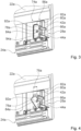
- the rounded portions can create a space in a tilted state of the rocker element 78a through which the not completely locked locking element 42a, 44a can be moved past the rocker element 78a into the recess 52a (see Figure 5 ). This makes it easy to repair the locking element 42a, 44a that is not fully locked.
- the rocker element 78a is provided to be tilted by the other, fully locked locking element 42a, 44a and thereby to allow a displacement of the locked door unit 22a in the closing direction 38a by the indication length 76a. If one of the two locking elements 42a, 44a is not fully locked and does not engage in the recess 52a which forms the form-locking elements 46a, 48a, only the one fully locked locking element 42a, 44a rests on the rocker element 78a, in particular on the contact side 86a of the rocker element 78a.
- Figure 4 is shown by way of example how only the upper locking element 42a is fully locked and the lower locking element 44a is not fully locked, for example due to a defect.
- the fully locked locking element 42a engages in the recess 52a of the locking base body 52a.
- the not fully locked locking element 44a does not engage in the recess 52a of the locking base body 50a.
- the not fully locked locking element 44a is in its unlocked position. As a result, only the fully locked locking element 42a cuts the rocker element 78a and comes into contact with it. The other, not fully locked locking element 44a does not come into contact with the rocker element 78a.
- the rocker element 78a is thrown out of balance by the one-sided contact with the locked locking element 42a and is pivoted by the spring force of the spring device 68a, which acts on the door unit 22a in the closing direction 38a. By pivoting, the rocker element 78a clears a path through which the door unit 22a can be displaced by the indication length 76a until the fully locked locking element 42a rests against a wall of the recess 52a, which forms the corresponding form-fitting element 46a.
- the contact surface of the The form-locking elements 42a, 44a are spaced apart in the closing direction by the indication length from the contact side 86a of the rocker element 78a in the neutral position.
- the door unit 22a can be displaced in the closing direction 38a by the indication length 76a due to the spring force of the spring device 68a.
- the locking state indication unit 74a comprises a sensor device 88a, which is intended to indirectly detect an incomplete locking of one of the locking elements 42a, 44a.
- the sensor device 88a is in particular intended to detect a displacement of the door unit 22a in the closing direction by the indication length 76a.
- the sensor device 88a is intended to output a fault signal when the door unit 22a is displaced by the indication length in the closing direction 38a.
- the control unit 62a is intended to evaluate the fault signal of the sensor device 88a. By evaluating the fault signal of the sensor device 88a, the control unit 62a can advantageously determine a displacement of the door unit 22a by the indication length 76a and thereby detect an incomplete locking of one of the two locking elements 42a, 44a.
- the sensor device 88a is designed as one piece with the sensor device 64a of the aircraft seat module, which is designed as a door sensor unit. This means that the sensor device 64a can advantageously be used for the locking state indication unit 74a, thus saving components. In principle, it would of course also be conceivable for the locking state indication unit 74a to have a separately designed sensor that detects a displacement of the door unit 22a in the closing direction by the indication length 76a.
- the locking state indication unit 74a has an indication unit 90a.
- the indication unit 90a is provided to indicate an incomplete locking of one of the two locking elements 42a, 44a.
- the indication unit 90a is provided to output a visual signal when one of the two locking elements 42a, 44a is incompletely locked.
- the indication unit 90a is preferably provided to indicate at least two different output signals in order to indicate, on the one hand, an incomplete locking of one of the locking elements 42a, 44a and, on the other hand, a complete locking of both Locking elements 42a, 44a.
- the indication unit 90a is designed as a light source.
- the indication unit 90a designed as a light source is intended to display at least two different colors.
- the indication unit 90a is intended to emit a red light, for example, when one of the locking elements 42a, 44a is not fully locked and a red light when both locking elements 42a, 44a are fully locked. In principle, it is also conceivable for the indication unit 90a to only emit a signal when one of the two locking elements 42a, 44a is not fully locked. In principle, it is also conceivable for the indication unit 90a to be designed differently and to emit a different visual, acoustic and/or haptic output signal.
- the indication unit 90a is arranged separately from the locking elements 42a, 44a in an upper region of the door unit 22a.
- the indication unit 90a is advantageously arranged at a height that can easily be seen by a person, for example on-board personnel. In principle, it is also conceivable that the indication unit 90a is arranged in an upper region of the housing unit 14a.
- the locking state indication unit 74a preferably has a further indication unit 108a.
- the further indication unit 108a is purely mechanical.
- the further indication unit 108a is preferably partially formed by the door unit 22a.
- the further indication unit 108a has a first marking that is arranged on the door unit 22a.
- the indication unit 104a has a second marking that is arranged on the housing unit 14a. In a fully open position of the door unit 22a, in which both locking elements 42a, 44a are fully locked, the two markings of the indication unit 108a are congruent.
- the markings of the indication unit 108a are no longer congruent, which indicates an incomplete locking of one of the two locking elements 42a, 44a.
- the purely mechanical indication unit 108a has a viewing window in the door unit 22a, which, when the door unit 22a is displaced in the closing direction 38a by the indication length, is congruent with a indication marking is arranged, which can then be seen from the aisle area 20a.
- the locking state indication unit 74a described above is designed to be purely mechanical and only has the purely mechanical additional indication unit 104a.
- the purely mechanical indication unit 104a can be dispensed with.
- FIG. 7 and 8 A further embodiment of the invention is shown.
- the following descriptions and the drawings are essentially limited to the differences between the embodiments, whereby with regard to identically designated components, in particular with regard to components with the same reference numerals, reference is also generally made to the drawings and/or the description of the other embodiments, in particular the Fig. 1 to 6 , can be referred to.
- the letter a is added to the reference numerals of the embodiment in Fig. 1 to 6
- the letter a is replaced by the letter b.
- the Figures 7 and 8 show a part of an aircraft seat module in a second embodiment.
- the aircraft seat module comprises a door unit 22b.
- the door unit 22b is intended to at least partially delimit a passenger seat area 10b from an adjacent cabin area, in particular an aisle area 20b, at least in one operating state.
- the aircraft seat module has a bearing device 24b for supporting the door unit 22b.
- the door unit 22b can be adjusted between the open position and the closed position by means of the bearing device 24b.
- the aircraft seat module comprises a locking device 28b.
- the locking device 28b is intended to lock the door unit 22b in the maximum open stowed position.
- the locking device 28b comprises an electrically and/or electronically controllable actuator device 56b.
- the actuator device 56b comprises a first locking element 42b.
- the actuator device 56b comprises a second locking element 44b.
- the locking device comprises a locking state indication unit 74b.
- the locking state indication unit 74b is provided to detect and indicate an incomplete locking of at least one of the two locking elements 42b, 44b, at least in the maximum open position of the door unit 22b.
- the Figures 7 and 8 show an alternative embodiment of the locking state indication unit 74b.
- the locking state indication unit 74b of the second embodiment is provided to detect an incomplete locking of a locking element 42b, 44b directly on the corresponding locking element 42b, 44b.
- the locking state indication unit 74b is designed to be purely mechanical.
- the locking state indication unit 74b has a spring-loaded indication element 96b, 98b for each locking element 42b, 44b, which are intended to be deflected from a first position into a second position when the door unit 22b is locked by the respective locking element 42b, 44b in its locking position.
- the spring-loaded indication elements 96b, 98b are movably, in particular pivotably, attached to a locking base body 50b of the locking module. In principle, it would also be conceivable for the indication elements 96b, 98b to be movably connected to the door unit.
- the indication elements 96b, 98b are intended to be adjusted by one of the locking elements 42b, 44b when it is adjusted to the locking position.
- the indication elements 96b, 98b are in a first position, which forms a first indication position.
- the respective indication element 96b, 98b indicates that the locking element is incomplete or not in the locking position.
- a first visible surface 104b which is colored red, for example, is visible.
- the indication elements 96b, 98b are adjusted by the respective locking element.
- the respective indication element 96b, 98b indicates that the respective locking element 42b, 44b is completely locked.
- a second visible surface 106b which is colored green, for example, is visible.
- Locking state indication unit 74b has each spring-loaded indication element 96b, 98b has a viewing window 100b, 102b through which a position of the respective indication element 96b, 98b can be seen. Depending on a position of the indication elements 96b, 98b, one of the two viewing surfaces 104b, 106b of the respective indication element 96b, 98b to be displayed is visible through the viewing windows 100b, 102b.
Landscapes
- Engineering & Computer Science (AREA)
- Mechanical Engineering (AREA)
- Aviation & Aerospace Engineering (AREA)
- Physics & Mathematics (AREA)
- Electromagnetism (AREA)
- Lock And Its Accessories (AREA)
Description
- Die Erfindung betrifft ein Flugzeugsitzmodul nach dem Oberbegriff des Patentanspruchs 1.
- Die Druckschrift
EP 3 225 548 A1 offenbart ein Flugzeugsitzmodul mit einem Fluggastsitzbereich, mit einer Türeinheit, die zumindest dazu vorgesehen ist, zumindest in einem Betriebszustand einen Durchgangsbereich zu dem Fluggastsitzbereich zu verschließen, mit einer Verriegelungsvorrichtung für die Türeinheit, die dazu vorgesehen ist, die Türeinheit in einer geöffneten Stellung, insbesondere einer maximal geöffneten Verstaustellung, zu verriegeln und dazu zumindest eine Aktuatorvorrichtung umfasst, die zumindest zwei beweglich gelagerte Verriegelungselemente aufweist, die jeweils zwischen einer Verriegelposition und einer Entriegelposition verstellbar sind. - Die Druckschrift
US 2013/0241247 A1 offenbart ein Flugzeugsitzmodul mit einem Fluggastsitzbereich, mit einer Türeinheit, die zumindest dazu vorgesehen ist, zumindest in einem Betriebszustand einen Durchgangsbereich zu dem Fluggastsitzbereich zu verschließen, mit einer Verriegelungsvorrichtung für die Türeinheit, die dazu vorgesehen ist, die Türeinheit in einer geöffneten Stellung, insbesondere einer maximal geöffneten Verstaustellung, zu verriegeln. - Die Aufgabe der Erfindung besteht insbesondere darin, eine gattungsgemäße Vorrichtung mit verbesserten Eigenschaften hinsichtlich einer Sicherheit bereitzustellen. Die Aufgabe wird erfindungsgemäß durch die Merkmale des Patentanspruchs 1 gelöst, während vorteilhafte Ausgestaltungen und Weiterbildungen der Erfindung den Unteransprüchen entnommen werden können.
- Die Erfindung geht aus von einem Flugzeugsitzmodul mit einem Fluggastsitzbereich, mit einer Türeinheit, die zumindest dazu vorgesehen ist, zumindest in einem Betriebszustand einen Durchgangsbereich zu dem Fluggastsitzbereich zu verschließen, mit einer Verriegelungsvorrichtung für die Türeinheit, die dazu vorgesehen ist, die Türeinheit in einer geöffneten Stellung, insbesondere einer maximal geöffneten Verstaustellung, zu verriegeln und dazu zumindest eine Aktuatorvorrichtung umfasst, die zumindest zwei beweglich gelagerte Verriegelungselemente aufweist, die jeweils zwischen einer Verriegelposition und einer Entriegelposition verstellbar sind.
- Es wird vorgeschlagen, dass die Verriegelungsvorrichtung eine Verriegelungszustandsindikationseinheit aufweist, die dazu vorgesehen ist, in der maximal geöffneten Stellung der Türeinheit eine unvollständige Verriegelung zumindest eines der beiden Verriegelungselemente zu erfassen und anzuzeigen.
- Unter einem "Flugzeugsitzmodul" soll vorzugsweise ein Modul verstanden werden, das einen Fluggastsitzbereich definiert und dazu wenigstens ein Umhausungselement, das den Fluggastsitzbereich zumindest teilweise von einem restlichen Kabinenbereich abtrennt, zumindest einen in dem Fluggastsitzbereich angeordneten Flugzeugsitz und weitere Elemente des Fluggastsitzbereichs umfasst, wie insbesondere eine Konsole, eine Ottomane und/oder eine Bildschirmeinheit. Der Flugzeugsitz ist vorzugsweise als ein Einzelsitz oder als ein Zweiersitz ausgebildet. Unter einem "Fluggastsitzbereich" soll vorzugsweise ein Bereich verstanden werden, in dem ein Flugzeugsitz, vorzugsweise ein als ein Einzelsitz ausgebildeter Flugzeugsitz, oder eine aus zwei Flugzeugsitzen gebildete Sitzeinheit angeordnet ist und der zum Aufenthalt wenigstens eines Passagiers während eines Fluges in einem Flugzeug vorgesehen ist. In einem Fluggastsitzbereich sind vorzugsweise weitere Elemente angeordnet, die von einem Passagier nutzbar sind, wie insbesondere eine Konsole, eine Ottomane, Verstaumöglichkeiten, Ablageelemente und/oder Entertainmentvorrichtungen. Der Fluggastsitzbereich ist als ein Teilbereich einer Kabine, vorzugsweise einer Flugzeugkabine, ausgebildet. Ein Fluggastsitzbereich grenzt vorzugsweise an zumindest einen Gangbereich der Kabine an. Unter einem "angrenzenden Kabinenbereich" soll vorzugsweise ein unmittelbar an den Fluggastsitzbereich angrenzender Bereich der Kabine, wie vorzugsweise ein Gangbereich, verstanden werden, über den der Fluggastsitzbereich von einem Passagier erreicht werden kann. Unter einer "Türeinheit" soll vorzugsweise eine Baugruppe verstanden werden, die dazu vorgesehen ist, den zumindest einen Fluggastsitzbereich in zumindest einem Betriebszustand zumindest teilweise von dem Rest der Kabine, vorzugsweise von zumindest einem Gangbereich der Kabine, abzutrennen. Vorzugsweise trennt die Türeinheit den zumindest einen Fluggastsitzbereich in zumindest einem Betriebszustand zumindest teilweise physisch, insbesondere so, dass ein Durchgang versperrt ist, und zumindest teilweise optisch, insbesondere zumindest teilweise blickdicht und vorzugsweise komplett blickdicht, von dem Rest der Kabine, insbesondere bis zu einer Höhe des wenigstens einen Umhausungselements, ab. Die Türeinheit ist zumindest zwischen einer geöffneten Stellung und einer geschlossenen Stellung verstellbar. Vorzugsweise kann die Türeinheit zusätzlich in zumindest einer Zwischenstellung zwischen dem geöffneten Zustand und dem geschlossenen Zustand gehalten werden. Die Türeinheit ist vorzugsweise aus einem festen Material, wie insbesondere einem Kunststoff, beispielsweise einem faserverstärkten Kunststoff, einem Verbundmaterial (Komposit-Platte), wie beispielsweise einem Sandwichmaterial mit einem Wabenkern, einem Metall, wie insbesondere einem Aluminium, oder von einem Rahmen, beispielsweise einem Aluminiumrahmen mit einer Bespannung aus einem Textil oder Leder, gebildet. Vorzugsweise kann eine Türeinheit auch als ein einfaches Abtrennelement, wie beispielsweise ein Privacy-Divider, ausgebildet sein. Unter einem "Durchgangsbereich" soll insbesondere ein Bereich verstanden werden, der zwischen dem Fluggastsitzbereich und dem Gangbereich der Kabine angeordnet ist, und durch den die beiden Bereiche miteinander verbunden sind. Durch den Durchgangsbereich kann sich eine Person, insbesondere ein Passagier, zwischen dem Fluggastsitzbereich und dem Gangbereich der Kabine bewegen. Unter einer "Lagervorrichtung" soll insbesondere eine Vorrichtung verstanden werden, die dazu vorgesehen ist, ein Bauteil, wie vorzugsweise die Türeinheit, zwischen zumindest zwei Stellungen beweglich zu lagern. Die Lagervorrichtung ist vorzugsweise insbesondere dazu vorgesehen, die Türeinheit zwischen einer maximal geschlossenen Stellung und einer maximal geöffneten Stellung beweglich zu lagern. Vorzugsweise ist die Lagervorrichtung dazu vorgesehen, die Türeinheit entlang einer Bewegungsbahn beweglich zu lagern, wobei die Bewegungsbahn vorzugsweise von einer geraden Bewegungsachse gebildet ist. Mittels der Lagervorrichtung ist die Türeinheit zwischen der geöffneten Stellung und der geschlossenen Stellung entlang der Bewegungsbahn axial verstellbar, vorzugsweise verschiebbar. Unter einer "maximal geöffneten Verstaustellung" soll vorzugsweise eine Stellung der Türeinheit verstanden werden, in der die Türeinheit vorzugsweise komplett aus dem Durchgangsbereich herausbewegt ist und den Durchgangsbereich dadurch komplett frei gibt. In der maximal geöffneten Stellung ist die Türeinheit vorzugsweise vollständig überlappend zu der Umhausungseinheit angeordnet. In der maximal geöffneten Stellung ist die Türeinheit von einem Gangbereich aus betrachtet vollständig hinter der Umhausungseinheit angeordnet. Es ist grundsätzlich denkbar, dass die Türeinheit in der maximal geöffneten Stellung in einem dafür vorgesehenen Innenraum der Umhausungseinheit angeordnet ist. Unter einer "geschlossenen Stellung" soll vorzugsweise eine Stellung der Türeinheit verstanden werden, in der die Türeinheit den Durchgangsbereich vollständig verschließt. In der geschlossenen Stellung erstreckt sich die Türeinheit vorzugsweise über die gesamte Strecke zwischen den Umhausungselementen der Umhausungseinheit, welche den Durchgangsbereich ausbilden. Unter einer "Verriegelungsvorrichtung" soll vorzugsweise eine Vorrichtung verstanden werden, die dazu vorgesehen ist, ein Element, wie vorzugsweise die Türeinheit, in zumindest einer Stellung, vorzugsweise in der maximal geöffneten Stellung, positionsfest zu verriegeln, also diese Stellung positionsfest zu fixieren. Vorzugsweise ist die Verriegelungsvorrichtung dazu vorgesehen, die Türeinheit form- und/oder kraftschlüssig zu verriegeln. Vorzugsweise weist die Verriegelungsvorrichtung wenigstens ein, besonders bevorzugst zwei, Verriegelungselement/e auf. Ein Verriegelungselement ist vorzugsweise dazu vorgesehen, in einer Verriegelstellung der Verriegelungsvorrichtung formschlüssig in ein äquivalent ausgebildetes Gegenstück einzugreifen. In der Verriegelstellung der Verriegelungsvorrichtung ist das Verriegelungselement vorzugsweise in einer Verriegelposition angeordnet. In einer Entriegelstellung der Verriegelungsvorrichtung ist das Verriegelungselement vorzugsweise in einer Entriegelposition angeordnet, in der das Verriegelungselement die Verriegelungsstellung nicht verriegelt. In der Entriegelposition steht das Verriegelungselement vorzugsweise nicht in einem formschlüssigen Kontakt mit dem entsprechenden Gegenstück, in das das Verriegelungselement zur formschlüssigen Verriegelung der Verriegelungsvorrichtung eingreift. Unter einer "Verriegelstellung der Verriegelungsvorrichtung" soll eine Stellung der Verriegelungsvorrichtung verstanden werden, in der die Türeinheit positionsfest verriegelbar ist. Vorzugsweise ist in der Verriegelstellung der Verriegelungsvorrichtung ein Verriegelungselement in einer Verriegelungsstellung angeordnet, in der das Verriegelungselement dazu vorgesehen ist, in das äquivalent ausgebildete Gegenstück einzugreifen. Vorzugsweise ist der zu verriegelnde Gegenstand, insbesondere der Türeinheit, lediglich in einer definierten Stellung, vorzugsweise der geschlossenen Stellung. Grundsätzlich ist es denkbar, dass die Türeinheit nicht verriegelt ist, wenn die Verriegelungsvorrichtung in ihrer Verriegelstellung ist, und zwar dann, wenn die Türeinheit nicht in ihrer geschlossenen Stellung angeordnet ist. Unter einer "Entriegelstellung der Verriegelungsvorrichtung" soll vorzugsweise eine Stellung der Verriegelungsvorrichtung verstanden werden, in der die Verriegelstellung dazu vorgesehen ist, eine Bewegung der Türeinheit freizugeben und diese nicht zu blockieren. In der Entriegelstellung ist die Türeinheit freigegeben und kann von der geöffneten Stellung in die geschlossene Stellung gebracht werden. Vorzugsweise kann die Türeinheit in der Entriegelstellung der Verriegelungsvorrichtung zwischen der geöffneten Stellung und der geschlossenen Stellung verstellt werden. Unter einer "elektrisch und/oder elektronisch ansteuerbaren Aktuatorvorrichtung" soll insbesondere eine Vorrichtung verstanden werden, die einen elektrischen oder elektronisch ansteuerbaren Aktuator aufweist, der bei einer elektrischen und/oder elektronischen Ansteuerung einen Betriebszustand ändert, wie beispielsweise eine Bewegung, vorzugsweise eine Axialbewegung, ausführt und/oder ein magnetisches Feld erzeugt. Unter einer "Verriegelungszustandsindikationseinheit" soll vorzugsweise eine Einheit verstanden werden, die einen Zustand einer Verriegelung der Verriegelungselemente, insbesondere eine unvollständige Verriegelung der Verriegelungselemente der Verriegelungsvorrichtung, erfasst und ein entsprechendes optisches, akustisches, optisches und/oder elektronisches Signal ausgibt, über das ein entsprechender Zustand, insbesondere eine unvollständige Verriegelung des Verriegelungselements indiziert, also angezeigt wird. Die Verriegelungszustandsindikationseinheit ist vorzugsweise dazu vorgesehen, anzuzeigen wenn eines der beiden Verriegelungselemente unvollständig verriegelt ist und die Türeinheit dadurch zwar teilweise verriegelt, aber nicht vorschriftsmäßig mit beiden Verriegelungselementen verriegelt ist. Unter einer "unvollständigen Verriegelung eines Verriegelungselements" soll insbesondere ein Zustand verstanden werden, in dem das Verriegelungselement nicht wie für die Verriegelstellung vorgesehen vollständig in ein entsprechendes Gegenstück formschlüssig eingreift. Bei einer unvollständigen Verriegelung eines Verriegelungselements greift das Verriegelungselement nicht formschlüssig in das dazu vorgesehene Gegenstück ein. Bei einer unvollständigen Verriegelung eines Verriegelungselements kann das Verriegelungselement die Türeinheit nicht in der Verriegelstellung halten. Unter "vorgesehen" soll insbesondere speziell ausgelegt und/oder ausgestattet verstanden werden. Darunter, dass ein Objekt zu einer bestimmten Funktion vorgesehen ist, soll insbesondere verstanden werden, dass das Objekt diese bestimmte Funktion in zumindest einem Anwendungs- und/oder Betriebszustand erfüllt und/oder ausführt. Durch eine erfindungsgemäße Ausgestaltung kann vorteilhaft einfach eine nicht korrekte Verriegelung der Türeinheit ermittelt und angezeigt werden. Durch die erfindungsgemäße Ausgestaltung kann insbesondere erkannt werden, wenn eines von zumindest zwei Verriegelungselementen nicht korrekt verriegelt ist und dies angezeigt werden. Dadurch kann beispielsweise ein Bordpersonal oder ein Passagier einfach auf eine nicht korrekt verriegelte Türeinheit hingewiesen werden. Dadurch können vorzugsweise gefährliche Situationen durch nicht korrekt verriegelte Türeinheiten vermieden werden, wenn durch eine einfach durchzuführende Kontrolle, beispielsweise vor einer Landung des Flugzeugs, erkannt werden kann, ob eine Türeinheit korrekt verriegelt ist. Dadurch kann vorteilhaft insbesondere eine Sicherheit der Flugzeugsitzvorrichtung erhöht werden.
- Weiter wird vorgeschlagen, dass die Verriegelungszustandsindikationseinheit eine Indikationseinheit aufweist, die eine unvollständige Verriegelung eines der beiden Verriegelungselemente anzeigt, getrennt von den Verriegelungselementen und vorzugsweise in einem oberen Bereich der Türeinheit angeordnet ist. Unter einer "Indikationseinheit" soll vorzugsweise eine Einheit verstanden werden, die ein optisches, akustisches und/oder haptisches Signal ausgeben kann, das von einer Person, beispielsweise von einem Bordpersonal erfasst werden kann. Unter "getrennt angeordnet" soll vorzugsweise verstanden werden, dass die entsprechenden Elemente, wie insbesondere die Indikationseinheit und die Verriegelungselemente, räumlich getrennt voneinander angeordnet sind und vorzugsweise keine direkte Verbindung miteinander aufweisen. Unter einem "oberen Bereich der Türeinheit" soll vorzugsweise ein oberes, einem Kabinenboden abgewandtes Drittel, besonders bevorzugt ein oberer Randbereich der Türeinheit, verstanden werden. Vorteilhaft ist die Indikationseinheit zwar in einem oberen Bereich der Türeinheit angeordnet, es ist aber grundsätzlich auch denkbar, dass die Indikationseinheit in einem anderen Bereich an der Türeinheit oder einer Umhausungseinheit angeordnet ist. Es ist grundsätzlich denkbar, dass die Indikationseinheit in einem kabinenbodennahen Bereich angeordnet ist, oder dass die Indikationseinheit in einem mittleren Bereich der Türeinheit oder der Umhausungseinheit angeordnet ist. Vorteilhaft ist die Indikationseinheit in einem von einer Person einfach einzusehenden Bereich angeordnet. Dadurch kann die Indikationseinheit vorteilhaft unabhängig von den Verriegelungselementen und besonders vorteilhaft in einem gut einzusehenden Bereich angeordnet werden, der leicht von einer Person gesehen werden kann.
- Ferner wird vorgeschlagen, dass die Verriegelungszustandsindikationseinheit bei einer unvollständigen Verriegelung eines der Verriegelungselemente dazu vorgesehen ist, eine Verschiebung der verriegelten Türeinheit in Schließrichtung um eine Indikationslänge zuzulassen. Unter einer "Indikationslänge" soll vorzugsweise eine definierte Länge verstanden werden, um die die Türeinheit in Schließrichtung verschoben werden kann, damit eine unvollständige Verriegelung erkannt werden kann. Die Indikationslänge beträgt vorzugsweise weniger als 30 mm, vorzugsweise unter 20 mm und in einer besonders bevorzugten Ausgestaltung weniger als 10 mm. Bei einer rein elektronischen Erfassung der Indikationslänge, beispielsweise durch eine Sensorvorrichtung, ist eine Indikationslänge von unter 10 mm denkbar, beispielsweise 5 mm. Bei einer direkten rein optischen Erfassung der Indikationslänge durch eine Person beträgt die Indikationslänge vorzugsweise 25 mm (1 Zoll). Dadurch kann eine unvollständige Verriegelung besonders einfach indiziert werden.
- Es wird weiterhin vorgeschlagen, dass die Verriegelungszustandsindikationseinheit zumindest ein Wippenelement aufweist, das dazu vorgesehen ist, die Verriegelungselemente in ihrer Verriegelposition zu kontaktieren. Unter einem "Wippenelement" soll vorzugsweise ein beweglich gelagertes Element verstanden werden, das um eine vorzugsweise im Wesentlichen mittig gelagerte Schwenkachse in zwei entgegengesetzte Drehrichtungen um einen definierten Schwenkwinkel verschwenkt werden kann. Das Wippenelement ist vorzugsweise dazu vorgesehen, eine Anlagefläche für die Verriegelungselemente bereitzustellen, an der die Verriegelungselemente anliegen. Das Wippenelement ist vorzugsweise dazu vorgesehen, von den vollständig verriegelten Verriegelungselementen in einer Neutralstellung gehalten zu werden. Dadurch kann die Verriegelungsindikationseinheit besonders einfach und vorteilhaft mechanisch ausgebildet werden.
- Des Weiteren wird vorgeschlagen, dass das Wippenelement um eine Schwenkachse verschwenkbar gelagert ist, die koaxial zu Bewegungsachsen der Verriegelungselemente verläuft und einen gleichen Abstand zu den Bewegungsachsen der Verriegelungselemente aufweist. Dadurch kann das Wippenelement besonders vorteilhaft angebracht werden.
- Weiterhin wird vorgeschlagen, dass das Wippenelement bei einer unvollständigen Verriegelung eines der Verriegelungselemente dazu vorgesehen ist, durch das andere Verriegelungselement verkippt zu werden und dadurch eine Verschiebung der verriegelten Türeinheit in Schließrichtung um eine Indikationslänge zuzulassen. Dadurch kann durch das Wippenelement besonders einfach eine unvollständige Verriegelung eines Verriegelungselements angezeigt werden.
- Außerdem wird vorgeschlagen, dass die Verriegelungszustandsindikationseinheit zumindest eine Sensorvorrichtung umfasst, die dazu vorgesehen ist, eine unvollständige Verriegelung eines der Verriegelungselemente, insbesondere indirekt zu erfassen. Unter einer "Sensorvorrichtung" soll vorzugsweise eine Vorrichtung verstanden werden, die dazu vorgesehen ist, zumindest eine Kenngröße und/oder eine physikalische Eigenschaft aufzunehmen, wobei die Aufnahme aktiv, wie insbesondere durch Erzeugen und Aussenden eines elektrischen Messsignals, und/oder passiv, wie insbesondere durch eine Erfassung von Eigenschaftsänderungen eines Sensorbauteils, stattfinden kann. Es sind verschiedene, dem Fachmann als sinnvoll erscheinende Sensorvorrichtungen denkbar, wie beispielsweise mechanische Sensoren (Schalter) oder REEd-Kontakte (Magnetschalter). Eine Sensorvorrichtung ist vorzugsweise dazu vorgesehen, ein elektrisches und/oder elektronisches Sensorsignal auszugeben, das vorzugsweise von einer entsprechenden Recheneinheit ausgewertet werden kann. Unter "indirekt erfassen" soll vorzugsweise verstanden werden, dass eine zu erfassende Kenngröße nicht direkt an dem zu erfassenden Element, wie insbesondere einem Verriegelungselement, erfasst wird, sondern an einem anderen Bauteil, wie insbesondere an der Türeinheit. Dadurch kann durch die Verriegelungszustandsindikationseinheit eine unvollständige Verriegelung eines Verriegelungselements besonders einfach erkannt werden.
- Es wird weiter vorgeschlagen, dass die Sensorvorrichtung einstückig mit einer als Türpositionssensor ausgebildeten Sensorvorrichtung ausgebildet ist. Unter einem "Türpositionssensor" soll vorzugsweise ein Sensor verstanden werden, der dazu vorgesehen ist, eine Position der Türeinheit, zu erfassen. Vorzugsweise ist der Türpositionssensor dazu vorgesehen, eine geöffnete Stellung der Türeinheit, insbesondere eine vollständige geöffnete Stellung der Türeinheit, zu erfassen.
- Grundsätzlich wäre es auch denkbar, dass der Türpositionssensor eine genaue Position zwischen der geöffneten und der geschlossenen Stellung der Türeinheit erfassen kann. Dadurch kann vorteilhaft ein vorhandener Sensor, insbesondere der Türpositionssensor als Sensoreinheit zur indirekten Erfassung einer unvollständigen Verriegelung verwendet werden. Dadurch können vorteilhaft insbesondere Bauteilkosten verringert werden.
- Zudem wird vorgeschlagen, dass die Indikationseinheit zumindest teilweise von der Türeinheit ausgebildet ist. Dadurch kann die Indikationseinheit besonders einfach und kostengünstig ausgebildet werden.
- Weiter wird vorgeschlagen, dass die Verriegelungszustandsindikationseinheit je Verriegelungselement ein federbelastetes Indikationselement aufweist, die dazu vorgesehen sind, bei einer Verriegelung der Türeinheit durch das jeweilige Verriegelungselement in seiner Verriegelstellung aus einer ersten Stellung in eine zweite Stellung ausgelenkt zu werden. Unter einem "federbelasteten Indikationselement" soll vorzugsweise ein Indikationselement verstanden werden, das durch eine Federkraft in eine erste Anzeigeposition gedrückt wird und durch eine einwirkende Aktuationskraft, vorzugsweise eine durch ein Verriegelungselement einwirkende Kraft entgegen der Federkraft in eine zweite Anzeigeposition gebracht werden kann. Nach Wegfall der Aktuationskraft wird das federbelastete Indikationselement durch die Federkraft selbsttätig in die erste Anzeigeposition zurückgestellt. Dadurch kann eine alternative Indikationseinheit für die Verriegelungszustandsindikationseinheit bereitgestellt werden.
- Ferner wird vorgeschlagen, dass die Verriegelungszustandsindikationseinheit je federbelastetem Indikationselement ein Sichtfenster aufweist, durch das eine Stellung des jeweiligen Indikationselements einsehbar ist. Dadurch kann eine Stellung der Indikationselemente besonders einfach von einer Person gesehen werden.
- Des Weiteren wird vorgeschlagen, dass die Verriegelungszustandsindikationseinheit rein mechanisch ausgebildet ist. Darunter, dass die "Verriegelungszustandsindikationseinheit rein mechanisch ausgebildet ist" soll vorzugsweise verstanden werden, dass die Verriegelungszustandsindikationseinheit lediglich aus mechanischen Bauteilen aufgebaut ist und insbesondere keine elektrischen oder elektronischen Bauteile aufweist. Dadurch kann die Verriegelungszustandsindikationseinheit besonders kostengünstig ausgebildet werden.
- Das erfindungsgemäße Flugzeugsitzmodul soll hierbei nicht auf die oben beschriebene Anwendung und Ausführungsform beschränkt sein. Insbesondere kann das erfindungsgemäße Flugzeugsitzmodul zu einer Erfüllung einer hierin beschriebenen Funktionsweise eine von einer hierin genannten Anzahl von einzelnen Elementen, Bauteilen und Einheiten abweichende Anzahl aufweisen.
- Weitere Vorteile ergeben sich aus der folgenden Zeichnungsbeschreibung. In den Zeichnungen sind zwei Ausführungsbeispiele der Erfindung dargestellt. Die Zeichnungen, die Beschreibung und die Ansprüche enthalten zahlreiche Merkmale in Kombination. Der Fachmann wird die Merkmale zweckmäßigerweise auch einzeln betrachten und zu sinnvollen weiteren Kombinationen zusammenfassen.
- Es zeigen:
- Fig. 1
- eine schematisierte Ansicht eines Flugzeugsitzmoduls, mit einer Umhausungseinheit und einer Türeinheit,
- Fig. 2
- eine schematisierte Ansicht einer Türeinheit mit einer Verriegelungsvorrichtung,
- Fig. 3
- eine schematische Ansicht der Verriegelungsvorrichtung mit zwei Verriegelungselementen in ihrer Verriegelstellung und einer Verriegelungszustandsindikationseinheit,
- Fig. 4
- eine schematische Darstellung der Verriegelungsvorrichtung und der Verriegelungszustandsindikationseinheit mit einem Verriegelungselement, das nicht vollständig verriegelt ist,
- Fig. 5
- eine weitere schematische Darstellung der Verriegelungsvorrichtung und der Verriegelungszustandsindikationseinheit mit einem Verriegelungselement, das nicht vollständig verriegelt ist,
- Fig. 6
- eine schematische Darstellung der Türeinheit mit einer Sensorvorrichtung die als ein Türsensor ausgebildet ist,
- Fig. 7
- eine schematische Darstellung einer Verriegelungszustandsindikationseinheit in einem zweiten Ausführungsbeispiel, die rein mechanisch ausgebildet ist, und
- Fig. 8
- eine weitere Ansicht der Türeinheit mit einer Verriegelungszustandsindikationseinheit in dem zweiten Ausführungsbeispiel.
- In den
Figuren 1 bis 6 ist ein Flugzeugsitzmodul gezeigt. Das Flugzeugsitzmodul ist als ein Teil einer Innenausstattung einer Flugzeugkabine ausgebildet. In einer Flugzeugkabine sind vorzugsweise mehrere Flugzeugsitzmodule angeordnet. Das Flugzeugsitzmodul bildet einen Fluggastsitzbereich 10a aus. Der Fluggastsitzbereich 10a ist als ein Bereich ausgebildet, den insbesondere ein Passagier während eines Fluges für sich zur Verfügung hat. Der Fluggastsitzbereich 10a ist vorzugsweise insbesondere als ein Businessclass- oder Firstclass-Fluggastsitzbereich ausgebildet. Die Flugzeugkabine weist zumindest einen Gangbereich 20a auf. Über den Gangbereich 20a ist der Fluggastsitzbereich 10a insbesondere für einen Passagier erreichbar. Das Flugzeugsitzmodul umfasst einen Flugzeugsitz 12a, der in dem Fluggastsitzbereich 10a angeordnet ist. Der Flugzeugsitz 12a ist vorzugsweise insbesondere als ein Flugzeugsitz 12a ausgebildet, der von zumindest einer Sitzposition in eine Liegeposition verstellbar ist. Das Flugzeugsitzmodul weist eine Umhausungseinheit 14a auf. Die Umhausungseinheit 14a ist dazu vorgesehen, den Fluggastsitzbereich 10a zumindest teilweise von einem Rest der Flugzeugkabine abzutrennen. Die Umhausungseinheit 14a ist dazu vorgesehen, den Fluggastsitzbereich 10a zumindest im Wesentlichen zu umgeben. Die Umhausungseinheit 14a ist insbesondere dazu vorgesehen, den Fluggastsitzbereich 10a räumlich von einem Rest der Flugzeugkabine, insbesondere einem Kabinengang, abzutrennen, um insbesondere eine erhöhte Privatsphäre für einen Passagier in dem Fluggastsitzbereich 10a zu schaffen. Die Umhausungseinheit 14a weist ein Umhausungselement 16a auf. Das Umhausungselement 16a umgibt den Fluggastsitzbereich 10a zumindest teilweise. Das Umhausungselement 16a kann grundsätzlich alleine oder zusammen mit einer Umhausungseinheit 14a eines anderen Flugzeugsitzmoduls den Fluggastsitzbereich 10a abtrennen. Die Umhausungseinheit 14a bildet einen Durchgangsbereich 18a aus. Der Durchgangsbereich 18a verbindet den Fluggastsitzbereich 10a und den angrenzenden Gangbereich 20a der Flugzeugkabine. Durch den Durchgangsbereich 18a kann eine Person, insbesondere ein Passagier, von dem Gangbereich 20a in den Fluggastsitzbereich 10a gelangen und umgekehrt. Der Durchgangsbereich 18a weist vorzugsweise eine Breite von 38 cm auf. - Das Flugzeugsitzmodul umfasst eine Türeinheit 22a. Die Türeinheit 22a ist dazu vorgesehen, zumindest in einem Betriebszustand den Fluggastsitzbereich 10a zumindest teilweise von einem angrenzenden Kabinenbereich, insbesondere dem Gangbereich 20a, abzugrenzen. Die Türeinheit 22a ist dazu vorgesehen, den Durchgangsbereich 18a in einer geschlossenen Stellung zu verschließen. In einer voll geschlossenen Stellung versperrt die Türeinheit 22a den Durchgangsbereich 18a komplett. Dabei ist es insbesondere denkbar, dass insbesondere in einem unteren Bereich eine Lücke zwischen der Türeinheit 22a und dem Kabinenboden vorhanden bleibt. In der voll geschlossenen Stellung erstreckt sich die Türeinheit 22a zumindest in einem Teilbereich vollständig zwischen dem Umhausungselement 16a und einem weiteren Umhausungselement 26a, die den Durchgangsbereich 18a begrenzen. Das weitere Umhausungselement 26a kann insbesondere ein Umhausungselement einer weiteren, vor der Umhausungseinheit 14a angeordneten weiteren Umhausungseinheit sein, die einen weiteren Flugzeugsitz umhaust. In einer geöffneten Stellung ist die Türeinheit 22a dazu vorgesehen, den Durchgangsbereich 18a freizugeben. In der geöffneten Stellung ist die Türeinheit 22a vorzugsweise komplett aus dem Durchgangsbereich 18a herausbewegt. Die Türeinheit 22a ist an der Umhausungseinheit 14a, insbesondere an dem Umhausungselement 16a, angebunden. Grundsätzlich wäre es ebenso denkbar, dass die Türeinheit 22a an dem weiteren Umhausungselement 26a der vorderen Umhausungseinheit angebunden ist.
- Das Flugzeugsitzmodul weist zur Lagerung der Türeinheit 22a eine Lagervorrichtung 24a auf. Die Lagervorrichtung 24a ist dazu vorgesehen, die Türeinheit 22a beweglich an der Umhausungseinheit 14a zu lagern. Die Türeinheit 22a ist über die Lagervorrichtung 24a an das Umhausungselement 16a angebunden. Mittels der Lagervorrichtung 24a ist die Türeinheit 22a zwischen der geöffneten Stellung und der geschlossenen Stellung verstellbar. Die Lagervorrichtung 24a ist vorzugsweise als eine Linearlagervorrichtung ausgebildet. Mittels der als Linearlagervorrichtung ausgebildeten Lagervorrichtung 24a ist die Türeinheit 22a linear zwischen einer geschlossenen Stellung und einer geöffneten Stellung verschiebbar. Mittels der Lagervorrichtung 24a ist die Türeinheit 22a in einer Schließrichtung 38a und in einer Öffnungsrichtung 40a bewegbar. Die Schließrichtung 38a und die Öffnungsrichtung 40a sind einander entgegengesetzte Richtungen der Bewegungsbahn, entlang der die Türeinheit 22a mittels der Lagervorrichtung 24a verschiebbar ist. Die Schließrichtung 38a ist ausgehend von der geöffneten Stellung der Türeinheit 22a parallel zu der Bewegungsbahn in Richtung der geschlossenen Stellung ausgerichtet. Die Schließrichtung 38a ist parallel zu der Bewegungsbahn von dem Umhausungselement 16a weggerichtet. Die Öffnungsrichtung 40a ist von der geschlossenen Stellung der Türeinheit 22a parallel zu der Bewegungsbahn in Richtung der geöffneten Stellung der Türeinheit 22a ausgerichtet. Die Öffnungsrichtung 40a ist parallel zu der Bewegungsbahn in Richtung des Umhausungselements 16a ausgerichtet.
- Die Lagervorrichtung 24a umfasst vorzugsweise zwei Lagermodule 30a, 32a. Die Lagervorrichtung 24a weist das erste Lagermodul 30a und das zweite Lagermodul 32a auf. Das erste Lagermodul 30a ist dazu vorgesehen, die Türeinheit 22a in einem oberen Bereich zu lagern. Das erste Lagermodul 30a ist insbesondere in einem oberen Bereich der Türeinheit 22a angeordnet. Das zweite Lagermodul 32a ist dazu vorgesehen, die Türeinheit 22a in einem unteren Bereich zu lagern. Das zweite Lagermodul 32a ist in einem unteren Bereich der Türeinheit 22a angeordnet. Durch die zwei Lagermodule 30a, 32a, die an zwei gegenüberliegenden Bereichen der Türeinheit 22a angeordnet sind, kann eine besonders gleichmäßige Lagerung der Türeinheit 22a erreicht werden. Die Lagermodule 30a, 32a weisen vorzugsweise jeweils ein erstes, als Linearlagerschiene ausgebildetes Lagerelement 34a und ein darin axial verschiebbar gelagert angeordnetes zweites Lagerelement 36a auf. Beispielsweise ist denkbar, dass das erste als Linearlagerschiene ausgebildete Lagerelement 34a fest mit der Umhausungseinheit 14a und das zweite Lagerelement 36a fest mit der Türeinheit 22a verbunden ist. Grundsätzlich ist es auch denkbar, dass die beiden Lagerelemente 34a, 36a jeweils genau anders herum angebunden sind.
- Das Flugzeugsitzmodul umfasst eine Verriegelungsvorrichtung 28a. Die Verriegelungsvorrichtung 28a ist dazu vorgesehen, die Türeinheit 22a in der geöffneten Stellung zu verriegeln. Die Verriegelungsvorrichtung 28a ist dazu vorgesehen, die Türeinheit 22a in der maximal geöffneten Verstaustellung zu verriegeln. Unter der geöffneten Stellung, in der die Verriegelungsvorrichtung 28a die Türeinheit 22a verriegeln kann, ist vorzugsweise eine vollständig geöffnete Stellung zu verstehen. Vorzugsweise sind eine geöffnete Stellung und eine vollständig geöffnete Stellung identisch. Im Unterschied zu der geöffneten Stellung gibt es eine teilweise geöffnete Stellung und die geschlossene Stellung der Türeinheit 22a. Die Verriegelungsvorrichtung 28a ist dazu vorgesehen, die Türeinheit 22a in einer Verriegelstellung zu verriegeln und in einer Entriegelstellung eine Bewegung der Türeinheit 22a entlang der Bewegungsbahn der Türeinheit 22a freizugeben. Durch die Verriegelung der Türeinheit 22a in der geöffneten Stellung ist die Türeinheit 22a vorteilhaft gesichert und der Durchgangsbereich 18a ist freigegeben.
- Die Verriegelungsvorrichtung 28a umfasst eine elektrisch und/oder elektronisch ansteuerbare Aktuatorvorrichtung 56a. Die Aktuatorvorrichtung 56a umfasst ein erstes Verriegelungselement 42a. Die Aktuatorvorrichtung 56a umfasst ein zweites Verriegelungselement 44a. Durch das zweite Verriegelungselement 44a kann vorteilhaft eine Redundanz erreicht werden, wodurch die Verriegelungsvorrichtung 28a bei einem Ausfall eines der Verriegelungselemente 42a, 44a immer noch einsatzfähig bleibt. Die Verriegelungselemente 42a, 44a sind als Verriegelungsstifte ausgebildet. Die als Verriegelungsstifte ausgebildeten Verriegelungselemente 42a, 44a weisen vorzugsweise einen kreisrunden Querschnitt auf. Grundsätzlich wäre es auch denkbar, dass die Verriegelungselemente 42a, 44a einen ovalen oder rechteckigen Querschnitt aufweisen. Die Verriegelungselemente 42a, 44a sind im Wesentlichen identisch ausgebildet. Die Verriegelungselemente 42a, 44a sind zwischen einer Verriegelposition und einer Entriegelposition verstellbar. Die Verriegelungselemente 42a, 44a sind entlang einer Bewegungsachse zwischen ihrer Verriegelposition und ihrer Entriegelposition linear verschiebbar. Die Aktuatorvorrichtung 56a weist einen Grundkörper 66a auf. Die Verriegelungselemente 42a, 44a sind beweglich in dem Grundkörper 66a gelagert. Die Verriegelungselemente 42a, 44a sind axial verschiebbar in dem Grundkörper 66a gelagert. Die Verriegelungselemente 42a, 44a sind zur Verstellung zwischen der Verriegelungsposition und der Entriegelposition axial verschiebbar. Die Verriegelungselemente 42a, 44a sind vorzugsweise federbelastet ausgebildet. Die Aktuatorvorrichtung 56a weist je Verriegelungselement 42a, 44a ein Federelement auf, das die Verriegelungselemente 42a, 44a jeweils in eine Richtung mit einer Federkraft beaufschlagt. Grundsätzlich wäre es auch denkbar, dass die Aktuatorvorrichtung 56a ein gemeinsames Federelement für beide Verriegelungselemente 42a, 44a aufweist. Die Verriegelungselemente 42a, 44a sind in Richtung ihrer Verriegelposition mit der Federkraft beaufschlagt. Die Verriegelungselemente 42a, 44a sind mittels der Federelemente so ausgebildet, dass ihre Verriegelposition eine Neutralstellung ausbildet, in die die Verriegelungselemente 42a, 44a automatisch verstellt werden. Die beiden Verriegelungselemente 42a, 44a sind nebeneinander angeordnet. Die Verriegelungselemente 42a, 44a sind beabstandet zueinander angeordnet. Insbesondere sind die Verriegelungselemente 42a, 44a in der Schließrichtung 38a bzw. Öffnungsrichtung 40a zueinander beabstandet angeordnet. Die Verriegelungselemente 42a, 44a sind in parallel zu der Bewegungsbahn, entlang der die Türeinheit 22a mittels der Lagervorrichtung 24a verschiebbar ist, beabstandet angeordnet. Die Verriegelungselemente 42a, 44a sind in einer Horizontalrichtung nebeneinander angeordnet. Grundsätzlich wäre es auch denkbar, dass die Verriegelungselemente 42a, 44a in einer Vertikalrichtung nebeneinander, also übereinander angeordnet sind. Die Verriegelungselemente 42a, 44a sind jeweils in einer Führungsausnehmung linear verschiebbar gelagert. Die Führungsausnehmungen sind vorzugsweise in dem Grundkörper 66a der Aktuatorvorrichtung 56a angeordnet. Die Verriegelungselemente 42a, 44a sind zur Verriegelung der Türeinheit 22a dazu vorgesehen, in der Verriegelstellung in ein Gegenstück formschlüssig einzugreifen.
- Die Verriegelungsvorrichtung 28a umfasst je Verriegelungselement 42a, 44a ein Formschlusselement 46a, 48a, in das das entsprechende Verriegelungselement 42a, 44a zur Verriegelung formschlüssig eingreift. Die Formschlusselemente 46a, 48a sind als Ausnehmungen ausgebildet. Die als Ausnehmungen ausgebildeten Formschlusselemente 46a, 48a weisen eine Erstreckung auf, die größer ist als die darin eingreifenden Verriegelungselemente 42a, 44a. Die Formschlusselemente 46a, 48a weisen insbesondere in Bewegungsrichtung der Türeinheit 22a eine Erstreckung auf, die größer ist als eine entsprechende Erstreckung der Verriegelungselemente 42a, 44a. Dadurch hat ein entsprechendes in das Formschlusselement 46a, 48a eingreifendes Verriegelungselement 42a, 44a einen definierten Bewegungsfreiraum in dem Formschlusselement 46a, 48a. Die Verriegelungsvorrichtung 28a umfasst einen Verriegelungsgrundkörper 50a. Die Formschlusselemente 46a, 48a sind in den Verriegelungsgrundkörper 50a eingebracht. Die Formschlusselemente 46a, 48a sind in eine Oberseite des Verriegelungsgrundkörpers 50a eingebracht. Vorzugsweise sind die beiden Formschlusselemente 46a, 48a gemeinsam ausgebildet. Die beiden Formschlusselemente 46a, 48a sind als eine gemeinsame Ausnehmung 52a ausgebildet. Durch eine gemeinsame Ausbildung der Formschlusselemente 46a, 48a durch die gemeinsame Ausnehmung 52a kann der Verriegelungsgrundkörper 50a besonders einfach ausgebildet werden. Der Verriegelungsgrundkörper 50a ist vorzugsweise aus einem Metall gebildet. Der Verriegelungsgrundkörper 50a ist als ein separates Bauteil ausgebildet. Der Verriegelungsgrundkörper 50a ist vorzugsweise dazu vorgesehen, in einem Montageschritt fest an einem Bauteil des Flugzeugsitzmoduls, vorzugsweise der Türeinheit 22a oder der Umhausungseinheit 14a, montiert zu werden. In dem gezeigten Ausführungsbeispiel ist der Verriegelungsgrundkörper 50a vorzugsweise fest mit der Türeinheit 22a verbunden. Der Verriegelungsgrundkörper 50a ist an einer Innenseite der Türeinheit 22a angebunden. Der Verriegelungsgrundkörper 50a ist vorzugsweise mit der Türeinheit 22a verschraubt. Grundsätzlich wäre es ebenso denkbar, dass der Verriegelungsgrundkörper 50a einstückig mit der Türeinheit 22a ausgebildet ist. Der Verriegelungsgrundkörper 50a bildet eine gegenüber der Innenseite der Türeinheit 22a erhöhte Oberfläche aus.
- Die elektrisch und/oder elektronisch ansteuerbare Aktuatorvorrichtung 56a ist dazu vorgesehen, zur Entriegelung der Türeinheit 22a elektrisch und/oder elektronisch angesteuert zu werden. Durch die Aktuatorvorrichtung 56a sind die federbelasteten Verriegelungselemente 42a, 44a aktiv in ihre Entriegelposition verstellbar. Die Aktuatorvorrichtung 56a umfasst einen Aktuator 58a. Der Aktuator 58a ist als ein elektromechanischer Aktuator ausgebildet. Vorzugsweise ist der Aktuator 58a als ein elektromagnetischer Aktuator ausgebildet. Das Betätigungselement des Aktuators 58a ist mit den beiden Verriegelungselementen 42a, 44a gekoppelt. Durch Betätigung des Aktuators 58a können die beiden Verriegelungselemente 42a, 44a verstellt werden. Die beiden Verriegelungselemente 42a, 44a können durch eine Betätigung des Aktuators 58a von ihrer Verriegelstellung in ihre Entriegelstellung verstellt werden. In einem nicht betätigten Zustand des Aktuators 58a ist das Betätigungselement des Aktuators 58a in einer Neutralposition angeordnet. Grundsätzlich ist es denkbar, dass die Aktuatorvorrichtung 56a zwei separate Aktuatoren 58a aufweist, die jeweils mit einem der Verriegelungselemente 42a, 44a gekoppelt sind und dieses verstellen. Die elektrisch und/oder elektronisch ansteuerbare Aktuatorvorrichtung 56a ist an der Umhausungseinheit 14a angebunden. Vorzugsweise ist die elektrisch und/oder elektronisch ansteuerbare Aktuatorvorrichtung 56a an dem Umhausungselement 16a angebunden.
- Die Verriegelungsvorrichtung 28a umfasst einen Betätigungsschalter 60a. Der Betätigungsschalter 60a ist dazu vorgesehen, ein Auslösesignal auszugeben, das dazu vorgesehen ist, die Aktuatorvorrichtung 56a anzusteuern. Mittels des Betätigungsschalters 60a kann die Aktuatorvorrichtung 56a betätigt und damit in einen aktivierten Zustand geschaltet werden. Vorzugsweise weist das Flugzeugsitzmodul ein Steuergerät 62a auf. Das Steuergerät 62a ist vorzugsweise als ein Flugzeugsitzsteuergerät ausgebildet. Das Auslösesignal des Betätigungsschalters 60a wird vorzugsweise von dem Steuergerät 62a ausgewertet und die Aktuatorvorrichtung 56a entsprechend angesteuert.
- Das Flugzeugsitzmodul umfasst eine Sensorvorrichtung 64a, die zumindest zur Erfassung der Türeinheit 22a in der geöffneten Stellung vorgesehen ist. Die Sensorvorrichtung 64a ist als ein Türpositionssensor ausgebildet. Die Sensorvorrichtung 64a ist dazu vorgesehen, zu erkennen, wenn die Türeinheit 22a in ihrer geöffneten Stellung angeordnet ist und entsprechend mit der Verriegelungsvorrichtung 28a verriegelbar ist. Die Sensorvorrichtung 64a kann dabei vorzugsweise auch als ein Tastelement ausgebildet sein, das in der geöffneten Stellung der Türeinheit 22a durch einen entsprechenden Anschlag betätigt wird. Grundsätzlich ist es auch denkbar, dass die Sensorvorrichtung 64a als eine kontaktlose Sensorvorrichtung ausgebildet ist.
- Das Flugzeugsitzmodul umfasst eine Federvorrichtung 68a, die dazu vorgesehen ist, die Türeinheit 22a mit einer Federkraft zu beaufschlagen. Die Federvorrichtung 68a umfasst zwei Federelemente 70a, 72a. Grundsätzlich ist auch nur ein Federelement 70a, 72a denkbar. Die Federvorrichtung 68a ist funktionell zwischen der Türeinheit 22a und der Umhausungseinheit 14a angeordnet. Die Federvorrichtung 68a ist dazu vorgesehen, eine in Schließrichtung wirkende Federkraft auf die Türeinheit 22a auszuüben. Die Federvorrichtung 68a ist dazu vorgesehen, in einer geöffneten Stellung der Türeinheit 22a eine Federkraft auf die Türeinheit 22a auszuüben, um eine Schließbewegung der Türeinheit 22a zu unterstützen. Bei einer Verschiebung der Türeinheit 22a aus der geschlossenen Stellung in Öffnungsrichtung 40a, um die Verriegelungsvorrichtung 28a mittels des Betätigungsschalters 60a zu entriegeln, wird die Federvorrichtung 68a gestaucht. Dadurch kann durch die Verschiebung der Türeinheit 22a in Öffnungsrichtung 40a vorteilhaft eine Federkraft erhöht werden, durch die eine Schließbewegung der Türeinheit 22a vorteilhaft unterstützt wird.
- Die Verriegelungsvorrichtung umfasst eine Verriegelungszustandsindikationseinheit 74a. Die Verriegelungszustandsindikationseinheit 74a ist dazu vorgesehen, zumindest in der maximal geöffneten Stellung der Türeinheit 22a eine unvollständige Verriegelung zumindest eines der beiden Verriegelungselemente 42a, 44a zu erfassen und anzuzeigen. Die Verriegelungszustandsindikationseinheit 74a ist dazu vorgesehen, eine unvollständige Verriegelung der Verriegelungsvorrichtung 28a zu erfassen und anzuzeigen, wenn zumindest eines der beiden Verriegelungselemente unvollständig verriegelt ist. Die Verriegelungszustandsindikationseinheit 74a ist dazu vorgesehen, eine unvollständige Verriegelung der Verriegelungsvorrichtung 28a zu erfassen und anzuzeigen, wenn lediglich eines der Verriegelungselemente 42a, 44a unvollständig verriegelt ist. Durch die Erkennung einer unvollständigen Verriegelung eines der Verriegelungselemente 42a, 44a kann vorteilhaft früh erkannt werden, wenn eines der Verriegelungselemente 42a, 44a defekt ist und nicht mehr korrekt verriegelt werden kann, obwohl die Türeinheit 22a durch ein korrekt verriegeltes Verriegelungselement 42a, 44a in der geöffneten Stellung verriegelt ist. Dadurch kann eine Reparatur oder ein Austausch des einen Verriegelungselements 42a, 44a vorteilhaft früh veranlasst werden, sodass der Ausfall des anderen Verriegelungselements 42a, 44a und damit der dadurch resultierende zeitgleiche Defekt beider Verriegelungselemente 42a, 44a vorteilhaft vermieden werden kann.
- Die Verriegelungszustandsindikationseinheit 74a ist dazu vorgesehen, eine unvollständige Verriegelung eines der Verriegelungselemente 42a, 44a indirekt zu erfassen und anzuzeigen. Die Verriegelungszustandsindikationseinheit 74a ist dazu vorgesehen, bei einer unvollständigen Verriegelung eines der Verriegelungselemente 42a, 44a eine Verschiebung der verriegelten Türeinheit 22a in Schließrichtung 38a um eine Indikationslänge 76a zuzulassen. Die Türeinheit 22a ist dabei um die Indikationslänge 76a verschiebbar, obwohl sie durch eines der Verriegelungselemente 42a, 44a verriegelt ist. Bei einer unvollständigen Verriegelung der Türeinheit 22a durch die Verriegelungsvorrichtung 28a, also wenn eines der beiden Verriegelungselemente 42a, 44a unvollständig verriegelt ist, ist die Türeinheit 22a um die Indikationslänge 76a in Schließrichtung 38a verschiebbar. Bei einer vollständigen Verriegelung der Türeinheit 22a mittels der Verriegelungsvorrichtung 28a, also wenn beide Verriegelungselemente 42a, 44a vollständig verriegelt sind, ist die Türeinheit 22a nicht in Schließrichtung 38a verschiebbar. Die Verschiebung der Türeinheit 22a in Schließrichtung 38a um die Indikationslänge 76a wird bei einer unvollständigen Verriegelung der Verriegelungsvorrichtung 28a durch die Federkraft der Federvorrichtung 68a indiziert. Die Federvorrichtung 68a drückt die Türeinheit 22a um die Indikationslänge 76a in die Schließrichtung 38a, wenn die Verriegelungsvorrichtung 28a durch die unvollständige Verriegelung eines Verriegelungselements 42a, 44a nicht richtig verriegelt ist. Die Indikationslänge 76a, um die die Türeinheit 22a zur Erkennung einer unvollständigen Verriegelung verschoben wird, beträgt vorzugsweise 5 mm. Grundsätzlich ist es auch denkbar, dass die Indikationslänge 76a einen Wert zwischen 20 mm und 1 mm, beispielsweise 15mm, 10mm, 3mm oder 1,5mm beträgt.
- Die Verriegelungszustandsindikationseinheit 74a umfasst ein Wippenelement 78a. Das Wippenelement 78a ist dazu vorgesehen, die Verriegelungselemente 42a, 44a in ihrer Verriegelposition zu kontaktieren. In einem verriegelten Zustand der Türeinheit 22a in ihrer geöffneten Stellung liegen die Verriegelungselemente 42a, 44a in einem vollständig verriegelten Zustand an dem Wippenelement 78a an. Durch ein Anliegen beider Verriegelungselemente 42a, 44a in dem vollständig verriegelten Zustand wird das Wippenelement 78a in einer unausgelenkten Neutralstellung gehalten. Das Wippenelement 78a ist schwenkbar zu dem Verriegelungsgrundkörper 50a angeordnet.
- Zur Anbringung des Wippenelements 78a weist die Verriegelungszustandsindikationseinheit 74a einen Anbindungsrahmen 80a auf. Der Anbindungsrahmen 80a ist an dem Verriegelungsgrundkörper 50a angebunden. Grundsätzlich wäre es auch denkbar, dass der Anbindungsrahmen 80a einstückig mit dem Verriegelungsgrundkörper 50a ausgebildet ist. Der Anbindungsrahmen 80a ist auf einer der Aktuatorvorrichtung 56a zugewandten Seite des Verriegelungsgrundkörpers 50a angeordnet. Der Anbindungsrahmen 80a weist eine Durchgangsöffnung 82a auf, die größer ist als die Ausnehmung 52a in dem Verriegelungsgrundkörper 50a, welche die Formschlusselemente 46a, 48a ausbildet. Die Durchgangsöffnung 80a lässt einen Zugang zu den von der Ausnehmung 52a gebildeten Formschlusselementen 46a, 48a zu. Die Verriegelungselemente 42a, 44a erstrecken sich in einem vollständig verriegelten Zustand durch die Durchgangsöffnung 82a des Anbindungsrahmens 80a in die von der Ausnehmung 52a gebildeten Formschlusselemente 42a, 44a. Das Wippenelement 78a ist mit dem Anbindungsrahmen 80a verbunden. Das Wippenelement 78a ist schwenkbar mit dem Anbindungsrahmen 80a verbunden. Das Wippenelement 78a ist um eine Schwenkachse verschwenkbar an dem Anbindungsrahmen 80a gelagert. Die Schwenkachse, um die das Wippenelement 78a gelagert ist, verläuft koaxial zu den Bewegungsachsen der Verriegelungselemente 42a, 44a. Die Schwenkachse weist senkrecht gemessen einen gleichen Abstand zu den Bewegungsachsen der Verriegelungselemente 42a, 44a auf. Die Schwenkachse ist vorzugsweise mittig zwischen den von der Ausnehmung 52a ausgebildeten Formschlusselementen 46a, 48a angeordnet. Das Wippenelement 78a ist vorzugsweise auf einer Mittelachse der Ausnehmung 52a angebracht. Das Wippenelement 78a ist über einen Lagerbolzen 84a verschwenkbar mit dem Anbindungsrahmen 80a verbunden. Der Lagerbolzen 84a bildet die Schwenkachse aus.
- Das Wippenelement 78a ist als eine flache Platte ausgebildet. Das Wippenelement 78a weist eine Anlageseite 86a auf. Die Anlageseite 86a des Wippenelements 78a ist in einem montierten Zustand der Ausnehmung 52a zugewandt, welche die Formschlusselemente 46a, 48a ausbildet. Die Anlageseite 86a ist in der Neutralstellung parallel zu einer ersten Seite der Ausnehmung 52a ausgerichtet. In ihrer vollständig verriegelten Stellung liegen die Verriegelungselemente 42a, 44a an der Anlageseite 86a an dem Wippenelement 78a an. In einer Stellung, in der die Verriegelungselemente 42a, 44a in die Formschlusselemente 46a, 48a eingreifen, begrenzt die Anlageseite 86a des Wippenelements 78a eine Bewegung der Türeinheit 22a in Schließrichtung. Die Verriegelungselemente 42a, 44a stützen sich in der vollständig verriegelten Stellung über die Anlageseite 86a an dem Wippenelement 78a ab. Das Wippenelement 78a bildet ein Formschlusselement der Verriegelungsvorrichtung 28a für die Verriegelungselemente 42a, 44a aus. In einem vollständig verriegelten Zustand der Verriegelungsvorrichtung 28a, in dem beide Verriegelungselemente 42a, 44a vollständig verriegelt sind, bildet das Wippenelement 78a ein gemeinsames Formschlusselement für die Verriegelungselenente 42a, 44a aus (Siehe
Figur 3 ). Das Wippenelement 78a ist dabei in seiner Neutralstellung, wenn beide Verriegelungselemente 42a, 44a vollständig verriegelt sind. Die beiden Verriegelungselemente 42a, 44a halten, wenn beide vollständig verriegelt sind, das schwenkbar gelagerte Wippenelement 78a im Gleichgewicht, insbesondere in der Neutralstellung. Das Wippenelement 78a weist dazu an seiner Anlageseite 86a Kontaktierungsbereiche auf, an denen die Verriegelungselemente 42a, 44a anliegen. Die Kontaktierungsbereiche weisen jeweils einen gleich großen Abstand zu der Schwenkachse auf, um die das Wippenelement 78a gelagert ist. Der beiden Kontaktbereiche, an denen jeweils eines der Verriegelungselemente 42a, 44a anliegt, sind an aufeinander gegenüberliegenden Seiten der Schwenkachse des Wippenelements 78a angeordnet. Das Wippenelement 78a weist in seitlichen Kantenbereichen 92a, 94a der Anlageseite 86a Abrundungen auf. Durch die Abrundungen kann in einem verkippten Zustand des Wippenelements 78a ein Raum geschaffen werden, durch den das nicht vollständig verriegelte Verriegelungselement 42a, 44a an dem Wippenelement 78a vorbei in die Ausnehmung 52a bewegt werden kann (SieheFigur 5 ). So kann eine Reparatur des nicht vollständig verriegelten Verriegelungselements 42a, 44a einfach erfolgen. - Das Wippenelement 78a ist bei einer unvollständigen Verriegelung eines der Verriegelungselemente 42a, 44a dazu vorgesehen, durch das andere, vollständig verriegelte Verriegelungselement 42a, 44a verkippt zu werden und dadurch eine Verschiebung der verriegelten Türeinheit 22a in Schließrichtung 38a um die Indikationslänge 76a zuzulassen. Ist eines der beiden Verriegelungselemente 42a, 44a nicht vollständig verriegelt und greift nicht in die Ausnehmung 52a, welche die Formschlusselemente 46a, 48a ausbildet, ein, so liegt lediglich das eine vollständig verriegelte Verriegelungselement 42a, 44a an dem Wippenelement 78a, insbesondere an der Anlageseite 86a des Wippenelements 78a an. In
Figur 4 ist beispielhaft gezeigt, wie lediglich das obere Verriegelungselement 42a vollständig verriegelt ist und das untere Verriegelungselement 44a, beispielsweise durch einen Defekt, nicht vollständig verriegelt ist. Das vollständig verriegelte Verriegelungselement 42a greift in die Ausnehmung 52a des Verriegelungsgrundkörpers 52a ein. Das nicht vollständig verriegelte Verriegelungselement 44a greift nicht in die Ausnehmung 52a des Verriegelungsgrundkörpers 50a ein. Das nicht vollständig verriegelte Verriegelungselement 44a ist in seiner Entriegelstellung. Dadurch schneidet lediglich das vollständig verriegelte Verriegelungselement 42a das Wippenelement 78a und kommt mit diesem in Kontakt. Das andere, nicht vollständig verriegelte Verriegelungselement 44a kommt nicht in Kontakt mit dem Wippenelement 78a. Das Wippenelement 78a gerät durch die einseitige Anlage durch das verriegelte Verriegelungselement 42a aus dem Gleichgewicht und wird durch die Federkraft der Federvorrichtung 68a, welche in Schließrichtung 38a auf die Türeinheit 22a wirkt, verschwenkt. Durch das Verschwenken gibt das Wippenelement 78a einen Weg frei, durch den sich die Türeinheit 22a um die Indikationslänge 76a verschieben kann, bis das vollständig verriegelte Verriegelungselement 42a an einer Wandung der Ausnehmung 52a anliegt, die das entsprechende Formschlusselement 46a ausbildet. Die Anlagefläche der Formschlusselemente 42a, 44a ist in Schließrichtung um die Indikationslänge von der Anlageseite 86a des Wippenelements 78a in Neutralstellung beabstandet. Dadurch kann bei einem Verkippen des Wippenelements 76a durch die einseitige Anlage lediglich eines der Verriegelungselemente 42a, 44a eine Verschiebung der Türeinheit 22a in Schließrichtung 38a um die Indikationslänge 76a durch die Federkraft der Federvorrichtung 68a erfolgen. - Die Verriegelungszustandsindikationseinheit 74a umfasst eine Sensorvorrichtung 88a, die dazu vorgesehen ist, eine unvollständige Verriegelung eines der Verriegelungselemente 42a, 44a indirekt zu erfassen. Die Sensorvorrichtung 88a ist insbesondere dazu vorgesehen, eine Verschiebung der Türeinheit 22a in Schließrichtung um die Indikationslänge 76a zu erfassen. Die Sensorvorrichtung 88a ist dazu vorgesehen, bei einer Verschiebung der Türeinheit 22a um die Indikationslänge in der Schließrichtung 38a ein Störungssignal auszugeben. Das Steuergerät 62a ist dazu vorgesehen, das Störungssignal der Sensorvorrichtung 88a auszuwerten. Durch ein Auswerten des Störungssignals der Sensorvorrichtung 88a kann das Steuergerät 62a vorteilhaft eine Verschiebung der Türeinheit 22a um die Indikationslänge 76a ermitteln und dadurch eine unvollständige Verriegelung eines der beiden Verriegelungselemente 42a, 44a erfassen. Die Sensorvorrichtung 88a ist einstückig mit der als Türsensoreinheit ausgebildeten Sensorvorrichtung 64a des Flugzeugsitzmoduls ausgebildet. Dadurch kann vorteilhaft die Sensorvorrichtung 64a für die Verriegelungszustandsindikationseinheit 74a verwendet werden und so Bauteile eingespart werden. Grundsätzlich wäre natürlich auch denkbar, dass die Verriegelungszustandsindikationseinheit 74a einen separat ausgebildeten Sensor aufweist, der eine Verschiebung der Türeinheit 22a in Schließrichtung um die Indikationslänge 76a erfasst.
- Die Verriegelungszustandsindikationseinheit 74a weist eine Indikationseinheit 90a auf. Die Indikationseinheit 90a ist dazu vorgesehen, eine unvollständige Verriegelung einer der beiden Verriegelungselemente 42a, 44a anzuzeigen. Die Indikationseinheit 90a ist dazu vorgesehen, ein visuelles Signal auszugeben, wenn eines der beiden Verriegelungselemente 42a, 44a unvollständig verriegelt ist. Die Indikationseinheit 90a ist vorzugsweise dazu vorgesehen, zumindest zwei unterschiedliche Ausgangssignale anzuzeigen, um zum einen eine unvollständige Verriegelung eines der Verriegelungselemente 42a, 44a und zum anderen eine vollständige Verriegelung beider Verriegelungselemente 42a, 44a anzuzeigen. Die Indikationseinheit 90a ist als ein Leuchtmittel ausgebildet. Die als Leuchtmittel ausgebildete Indikationseinheit 90a ist dazu vorgesehen, zumindest zwei unterschiedliche Farben darzustellen. Die Indikationseinheit 90a ist dazu vorgesehen, bei einer unvollständigen Verriegelung eines der Verriegelungselemente 42a, 44a beispielsweise ein rotes Licht auszugeben und bei einer vollständigen Verriegelung beider Verriegelungselemente 42a, 44a ein rotes Licht. Grundsätzlich ist es auch denkbar, dass die Indikationseinheit 90a lediglich ein Signal ausgibt, wenn eines der beiden Verriegelungselemente 42a, 44a nicht vollständig verriegelt ist. Grundsätzlich ist ebenso denkbar, dass die Indikationseinheit 90a anders ausgebildet ist und ein anderes visuelles, akustisches und/oder haptisches Ausgangssignal ausgibt. Die Indikationseinheit 90a ist getrennt von den Verriegelungselementen 42a, 44a in einem oberen Bereich der Türeinheit 22a angeordnet. Dadurch ist die Indikationseinheit 90a vorteilhaft auf einer Höhe angeordnet, die leicht von einer Person, beispielsweise einem Bordpersonal erblickt werden kann. Grundsätzlich ist es auch denkbar, dass die Indikationseinheit 90a in einem oberen Bereich der Umhausungseinheit 14a angeordnet ist.
- Die Verriegelungszustandsindikationseinheit 74a weist vorzugsweise eine weitere Indikationseinheit 108a auf. Die weitere Indikationseinheit 108a ist rein mechanisch ausgebildet. Die weitere Indikationseinheit 108a ist vorzugsweise teilweise von der Türeinheit 22a ausgebildet. Die weitere Indikationseinheit 108a weist eine erste Markierung auf, die an der Türeinheit 22a angeordnet ist. Die Indikationseinheit 104a weist eine zweite Markierung auf, die an der Umhausungseinheit 14a angeordnet ist. In einer vollständig geöffneten Stellung der Türeinheit 22a, bei der beide Verriegelungselemente 42a, 44a vollständig verriegelt sind, sind die beiden Markierungen der Indikationseinheit 108a deckungsgleich. Ist die Türeinheit in einer Verriegelstellung der Türeinheit um die Indikationslänge 76a verschoben, da eines der beiden Verriegelungselemente 42a, 44a nicht vollständig verriegelt ist, sind die Markierungen der Indikationseinheit 108a nicht mehr deckungsgleich, wodurch eine unvollständige Verriegelung eines der beiden Verriegelungselemente 42a, 44a angezeigt wird. Grundsätzlich ist es auch denkbar, dass die rein mechanische Indikationseinheit 108a ein Sichtfenster in der Türeinheit 22a aufweist, das bei einer Verschiebung der Türeinheit 22a in Schließrichtung 38a um die Indikationslänge deckungsgleich mit einer Indikationsmarkierung angeordnet ist, die dann von dem Gangbereich 20a erblickt werden kann.
- Grundsätzlich wäre es in einer alternativen Ausgestaltung auch denkbar, dass die oben beschriebene Verriegelungszustandsindikationseinheit 74a rein mechanisch ausgebildet ist und lediglich die rein mechanische weitere Indikationseinheit 104a aufweist. Grundsätzlich ist es auch denkbar, dass auf die rein mechanische Indikationseinheit 104a verzichtet werden kann.
- In
Fig. 7 und 8 ist ein weiteres Ausführungsbeispiel der Erfindung gezeigt. Die nachfolgenden Beschreibungen und die Zeichnungen beschränken sich im Wesentlichen auf die Unterschiede zwischen den Ausführungsbeispielen, wobei bezüglich gleich bezeichneter Bauteile, insbesondere in Bezug auf Bauteile mit gleichen Bezugszeichen, grundsätzlich auch auf die Zeichnungen und/oder die Beschreibung der anderen Ausführungsbeispiele, insbesondere derFig. 1 bis 6 , verwiesen werden kann. Zur Unterscheidung der Ausführungsbeispiele ist der Buchstabe a den Bezugszeichen des Ausführungsbeispiels inFig. 1 bis 6 nachgestellt. In den Ausführungsbeispielen derFig. 7 bis 8 ist der Buchstabe a durch den Buchstaben b ersetzt. - Die
Figuren 7 und 8 zeigen einen Teil eines Flugzeugsitzmoduls in einem zweiten Ausführungsbeispiel. Das Flugzeugsitzmodul umfasst eine Türeinheit 22b. Die Türeinheit 22b ist dazu vorgesehen, zumindest in einem Betriebszustand einen Fluggastsitzbereich 10b zumindest teilweise von einem angrenzenden Kabinenbereich, insbesondere einem Gangbereich 20b, abzugrenzen. Das Flugzeugsitzmodul weist zur Lagerung der Türeinheit 22b eine Lagervorrichtung 24b auf. Mittels der Lagervorrichtung 24b ist die Türeinheit 22b zwischen der geöffneten Stellung und der geschlossenen Stellung verstellbar. Das Flugzeugsitzmodul umfasst eine Verriegelungsvorrichtung 28b. Die Verriegelungsvorrichtung 28b ist dazu vorgesehen, die Türeinheit 22b in der maximal geöffneten Verstaustellung zu verriegeln. Die Verriegelungsvorrichtung 28b umfasst eine elektrisch und/oder elektronisch ansteuerbare Aktuatorvorrichtung 56b. Die Aktuatorvorrichtung 56b umfasst ein erstes Verriegelungselement 42b. Die Aktuatorvorrichtung 56b umfasst ein zweites Verriegelungselement 44b. - Die Verriegelungsvorrichtung umfasst eine Verriegelungszustandsindikationseinheit 74b. Die Verriegelungszustandsindikationseinheit 74b ist dazu vorgesehen, zumindest in der maximal geöffneten Stellung der Türeinheit 22b eine unvollständige Verriegelung zumindest eines der beiden Verriegelungselemente 42b, 44b zu erfassen und anzuzeigen. Die
Figuren 7 und 8 zeigen eine alternative Ausgestaltung der Verriegelungszustandsindikationseinheit 74b. Anstatt einer indirekten Erfassung einer unvollständigen Verriegelung eines Verriegelungselements 42b, 44b ist die Verriegelungszustandsindikationseinheit 74b des zweiten Ausführungsbeispiels dazu vorgesehen, eine unvollständige Verriegelung eines Verriegelungselements 42b, 44b direkt an dem entsprechende Verriegelungselement 42b, 44b zu erfassen. Im Unterschied zu dem ersten Ausführungsbeispiel ist die Verriegelungszustandsindikationseinheit 74b rein mechanisch ausgebildet. - Die Verriegelungszustandsindikationseinheit 74b weist je Verriegelungselement 42b, 44b ein federbelastetes Indikationselement 96b, 98b auf, die dazu vorgesehen sind, bei einer Verriegelung der Türeinheit 22b durch das jeweilige Verriegelungselement 42b, 44b in seiner Verriegelstellung aus einer ersten Stellung in eine zweite Stellung ausgelenkt zu werden. Die federbelasteten Indikationselemente 96b, 98b sind beweglich, insbesondere verschwenkbar an einem Verriegelungsgrundkörper 50b des Verriegelungsmoduls angebracht. Grundsätzlich wäre es auch denkbar, dass die Indikationselemente 96b, 98b an der Türeinheit beweglich angebunden sind. Die Indikationselemente 96b, 98b sind dazu vorgesehen, durch jeweils eines der Verriegelungselemente 42b, 44b bei dessen Verstellung in die Verriegelposition verstellt zu werden. In einer Neutralstellung sind die Indikationselemente 96b, 98b in einer ersten Stellung, die eine erste Indikationsstellung ausbildet. In der ersten Indikationsstellung indiziert das jeweilige Indikationselement 96b, 98b eine unvollständig bzw. nicht in die Verriegelstellung verbrachtes Verriegelungselement. In der ersten Indikationsstellung ist dazu eine erste Sichtfläche 104b, die beispielsweise rot eingefärbt ist, sichtbar. In der zweiten Stellung, die eine zweite Indikationsstellung ausbildet, sind die Indikationselemente 96b, 98b von dem jeweiligen Verriegelungselement verstellt. In der zweiten Indikationsstellung indiziert das jeweilige Indiktionselement 96b, 98b, dass das jeweilige Verriegelungselement 42b, 44b vollständig verriegelt ist. In der zweiten Indikationsstellung ist dazu eine zweite Sichtfläche 106b, die beispielsweise grün eingefärbt ist, sichtbar. Die
- Verriegelungszustandsindikationseinheit 74b weist je federbelastetem Indikationselement 96b, 98b ein Sichtfenster 100b, 102b auf, durch das eine Stellung des jeweiligen Indikationselements 96b, 98b einsehbar ist. Durch die Sichtfenster 100b, 102b ist abhängig von einer Stellung der Indikationselemente 96b, 98b jeweils die eine anzuzeigende der beiden Sichtflächen 104b, 106b des jeweiligen Indikationselements 96b, 98b sichtbar.
-
- 10
- Fluggastsitzbereich
- 12
- Flugzeugsitz
- 14
- Umhausungseinheit
- 16
- Umhausungselement
- 18
- Durchgangsbereich
- 20
- Gangbereich
- 22
- Türeinheit
- 24
- Lagervorrichtung
- 26
- Umhausungselement
- 28
- Verriegelungsvorrichtung
- 30
- Lagermodul
- 32
- Lagermodul
- 34
- Lagerelement
- 36
- Lagerelement
- 38
- Schließrichtung
- 40
- Öffnungsrichtung
- 42
- Verriegelungselement
- 44
- Verriegelungselement
- 46
- Formschlusselement
- 48
- Formschlusselement
- 50
- Verriegelungsgrundkörper
- 52
- Ausnehmung
- 56
- Aktuatorvorrichtung
- 58
- Aktuator
- 60
- Betätigungsschalter
- 62
- Steuergerät
- 64
- Sensorvorrichtung
- 66
- Grundkörper
- 68
- Federvorrichtung
- 70
- Federelement
- 72
- Federelement
- 74
- Verriegelungszustandsindikationse inheit
- 76
- Indikationslänge
- 78
- Wippenelement
- 80
- Anbindungsrahmen
- 82
- Durchgangsöffnung
- 84
- Lagerbolzen
- 86
- Anlageseite
- 88
- Sensorvorrichtung
- 90
- Indikationseinheit
- 92
- Kantenbereich
- 94
- Kantenbereich
- 96
- Indikationselement
- 98
- Indikationselement
- 100
- Sichtfenster
- 102
- Sichtfenster
- 104
- Sichtfläche
- 106
- Sichtfläche
- 108
- Indikationseinheit
Claims (12)
- Flugzeugsitzmodul mit einem Fluggastsitzbereich (10a; 10b), mit einer Türeinheit (22a; 22b), die zumindest dazu vorgesehen ist, zumindest in einem Betriebszustand einen Durchgangsbereich (18a; 18b) zu dem Fluggastsitzbereich (10a; 10b) zu verschließen, mit einer Verriegelungsvorrichtung (28a; 28b) für die Türeinheit (22a; 22b), die dazu vorgesehen ist, die Türeinheit (22a; 22b) in einer geöffneten Stellung, insbesondere einer maximal geöffneten Verstaustellung, zu verriegeln und dazu zumindest eine Aktuatorvorrichtung (56a; 56b) umfasst, die zumindest zwei beweglich gelagerte Verriegelungselemente (42a, 44a; 42b, 44b) aufweist, die jeweils zwischen einer Verriegelposition und einer Entriegelposition verstellbar sind, dadurch gekennzeichnet, dass die Verriegelungsvorrichtung (28a; 28b) eine Verriegelungszustandsindikationseinheit (74a; 74b) aufweist, die dazu vorgesehen ist, in der maximal geöffneten Stellung der Türeinheit (22a; 22b) eine unvollständige Verriegelung zumindest eines der beiden Verriegelungselemente (42a, 44a; 42b, 44b) zu erfassen und anzuzeigen.
- Flugzeugsitzmodul nach Anspruch 1, dadurch gekennzeichnet, dass die Verriegelungszustandsindikationseinheit (74a) eine Indikationseinheit (90a) aufweist, die eine unvollständige Verriegelung einer der beiden Verriegelungselemente (42a, 44a) anzeigt, getrennt von den Verriegelungselementen (42a, 44a) und vorzugsweise in einem oberen Bereich der Türeinheit (22a) angeordnet ist.
- Flugzeugsitzmodul nach einem der vorhergehenden Ansprüche, dadurch gekennzeichnet, dass die Verriegelungszustandsindikationseinheit (74a) bei einer unvollständigen Verriegelung eines der Verriegelungselemente (42a, 44a) dazu vorgesehen ist, eine Verschiebung der verriegelten Türeinheit (22a) in Schließrichtung (38a) um eine Indikationslänge (76a) zuzulassen.
- Flugzeugsitzmodul nach einem der vorhergehenden Ansprüche, dadurch gekennzeichnet, dass die Verriegelungszustandsindikationseinheit (74a) zumindest ein Wippenelement (78a) aufweist, das dazu vorgesehen ist, die Verriegelungselemente (42a, 44a) in ihrer Verriegelposition zu kontaktieren.
- Flugzeugsitzmodul nach Anspruch 4, dadurch gekennzeichnet, dass das Wippenelement (78a) um eine Schwenkachse verschwenkbar gelagert ist, die koaxial zu Bewegungsachsen der Verriegelungselemente (42a, 44a) verläuft und einen gleichen Abstand zu den Bewegungsachsen der Verriegelungselemente (42a, 44a) aufweist.
- Flugzeugsitzmodul nach Anspruch 4 oder 5, dadurch gekennzeichnet, dass das Wippenelement (78a) bei einer unvollständigen Verriegelung eines der Verriegelungselemente (42a, 44a; 42b, 44b) dazu vorgesehen ist, durch das andere Verriegelungselement (42a, 44a; 42b, 44b) verkippt zu werden und dadurch eine Verschiebung der verriegelten Türeinheit (22a) in Schließrichtung (38a) um eine Indikationslänge (76a) zuzulassen.
- Flugzeugsitzmodul nach einem der vorhergehenden Ansprüche, dadurch gekennzeichnet, dass die Verriegelungszustandsindikationseinheit (74a) zumindest eine Sensorvorrichtung (88a) umfasst, die dazu vorgesehen ist, eine unvollständige Verriegelung eines der Verriegelungselemente (42a, 44a; 42b, 44b), insbesondere indirekt zu erfassen.
- Flugzeugsitzmodul nach Anspruch 7, dadurch gekennzeichnet, dass die Sensorvorrichtung (88a) einstückig mit einer als Türpositionssensor ausgebildeten Sensorvorrichtung (64a) ausgebildet ist.
- Flugzeugsitzmodul nach einem der vorhergehenden Ansprüche, dadurch gekennzeichnet, dass die Indikationseinheit (90a) zumindest teilweise von der Türeinheit (22a) ausgebildet ist.
- Flugzeugsitzmodul nach einem der vorhergehenden Ansprüche, dadurch gekennzeichnet, dass die Verriegelungszustandsindikationseinheit (74b) je Verriegelungselement (42b, 44b) ein federbelastetes Indikationselement (96b, 98b) aufweist, die dazu vorgesehen sind, bei einer Verriegelung der Türeinheit (22b) durch das jeweilige Verriegelungselement (42a, 44a; 42b, 44b) in seiner Verriegelstellung aus einer ersten Stellung in eine zweite Stellung ausgelenkt zu werden.
- Flugzeugsitzmodul nach Anspruch 9, dadurch gekennzeichnet, dass die Verriegelungszustandsindikationseinheit (74b) zumindest ein Sichtfenster (100b; 102b) aufweist, durch das eine Stellung zumindest eines der Indikationselemente (96b, 98b) einsehbar ist.
- Flugzeugsitzmodul zumindest nach Anspruch 1, dadurch gekennzeichnet, dass die Verriegelungszustandsindikationseinheit (74b) rein mechanisch ausgebildet ist.
Applications Claiming Priority (2)
| Application Number | Priority Date | Filing Date | Title |
|---|---|---|---|
| DE102020115567.0A DE102020115567A1 (de) | 2020-06-12 | 2020-06-12 | Flugzeugsitzmodul |
| PCT/EP2021/063026 WO2021249726A1 (de) | 2020-06-12 | 2021-05-17 | Flugzeugsitzmodul |
Publications (2)
| Publication Number | Publication Date |
|---|---|
| EP4164948A1 EP4164948A1 (de) | 2023-04-19 |
| EP4164948B1 true EP4164948B1 (de) | 2025-01-29 |
Family
ID=76283684
Family Applications (2)
| Application Number | Title | Priority Date | Filing Date |
|---|---|---|---|
| EP21730105.0A Active EP4165265B1 (de) | 2020-06-12 | 2021-05-17 | Flugzeugsitzmodul |
| EP21730104.3A Active EP4164948B1 (de) | 2020-06-12 | 2021-05-17 | Flugzeugsitzmodul |
Family Applications Before (1)
| Application Number | Title | Priority Date | Filing Date |
|---|---|---|---|
| EP21730105.0A Active EP4165265B1 (de) | 2020-06-12 | 2021-05-17 | Flugzeugsitzmodul |
Country Status (5)
| Country | Link |
|---|---|
| US (2) | US12559993B2 (de) |
| EP (2) | EP4165265B1 (de) |
| CN (1) | CN116209815B (de) |
| DE (1) | DE102020115567A1 (de) |
| WO (2) | WO2021249727A1 (de) |
Families Citing this family (1)
| Publication number | Priority date | Publication date | Assignee | Title |
|---|---|---|---|---|
| FR3165917A1 (fr) * | 2024-08-30 | 2026-03-06 | Airbus Helicopters | Système de verrouillage d’une porte d’aéronef comprenant un système de surveillance signalant si le système de verrouillage est dans un état verrouillé ou déverrouillé |
Family Cites Families (28)
| Publication number | Priority date | Publication date | Assignee | Title |
|---|---|---|---|---|
| DE10013295A1 (de) * | 2000-03-17 | 2001-09-20 | Geze Gmbh | Tür in Flucht- und Rettungswegen |
| DE10246643B4 (de) * | 2002-10-07 | 2015-03-19 | Gantner Electronic Gmbh | Elektromechanisches Schloss mit Sicherung gegen Fehlbetätigung |
| CN104245507B (zh) * | 2012-03-14 | 2017-08-01 | B/E航空公司 | 具有可展开的床延伸部的扶手组件 |
| EP2825458B1 (de) * | 2012-03-14 | 2018-11-28 | B/E Aerospace Inc. | Flugzeugpassagiersuite mit kombinationsbett |
| CA2913648C (en) * | 2012-06-05 | 2020-07-07 | Ashley Dean Olsson | Slam latch |
| EP3280642B1 (de) * | 2015-04-09 | 2020-09-23 | B/E Aerospace, Inc. | Verstellbares schiebewand-gerät |
| WO2017066559A1 (en) | 2015-10-14 | 2017-04-20 | B/E Aerospace, Inc. | Aircraft passenger suite privacy screen control apparatus and method |
| US10179650B2 (en) * | 2016-03-10 | 2019-01-15 | B/E Aerospace, Inc. | Sliding seating unit panel for providing enhanced passenger ingress and egress |
| GB2548901B (en) * | 2016-04-01 | 2018-07-25 | Thompson Aero Seating Ltd | Aircraft passenger seating with dual-mode privacy door |
| EP3290328B1 (de) * | 2016-09-05 | 2019-07-03 | Airbus Operations GmbH | Türeinheit für ein verkehrsmittel |
| GB2555123B (en) * | 2016-10-19 | 2020-04-29 | Thompson Aero Seating Ltd | Passenger seating with partition assembly |
| EP3541654B1 (de) * | 2016-11-15 | 2023-08-16 | Safran Seats USA LLC | Notausgangslösungen für mini-suiten |
| AT519593B1 (de) * | 2017-01-18 | 2019-05-15 | Facc Ag | Verriegelungsvorrichtung |
| US10421546B2 (en) * | 2017-04-04 | 2019-09-24 | Rockwell Collins, Inc. | Aircraft door and privacy panel assemblies |
| EP3606817B2 (de) * | 2017-04-04 | 2023-12-13 | Safran Seats | Durchgangssperre zwischen nebeneinander angeordneten sitzen |
| EP3543125A1 (de) * | 2018-03-23 | 2019-09-25 | Adient Aerospace LLC | Passgiersitzanordnung |
| FR3079495A1 (fr) * | 2018-03-27 | 2019-10-04 | Airbus Interiors Services | Aeronef presentant un module d'amenagement particulier |
| US11623749B2 (en) * | 2018-05-07 | 2023-04-11 | Safran Seats Usa Llc | Passenger seat privacy panel assembly |
| FR3084338B1 (fr) * | 2018-07-27 | 2021-02-12 | Zodiac Seats France | Module double portes pour sieges d'avion |
| DE102018126680A1 (de) * | 2018-10-25 | 2020-04-30 | Recaro Aircraft Seating Gmbh & Co. Kg | Flugzeugsitzvorrichtung |
| FR3089952B1 (fr) * | 2018-12-18 | 2020-11-27 | Safran Seats | Dispositif de fermeture d'un passage entre deux unites de sieges |
| EP3683138B1 (de) * | 2019-01-16 | 2021-04-28 | AIRBUS HELICOPTERS DEUTSCHLAND GmbH | Türverriegelungssystem mit einem schnellfreigabemechanismus |
| CN110593649B (zh) * | 2019-08-28 | 2022-04-12 | 广东好太太智能家居有限公司 | 一种具有自锁定功能的电子锁及系统 |
| DE102020104480A1 (de) * | 2019-09-30 | 2021-04-01 | Recaro Aircraft Seating Gmbh & Co. Kg | Flugzeugsitzmodul |
| WO2021084249A1 (en) * | 2019-10-29 | 2021-05-06 | Safran Seats GB Limited | An aircraft passenger accommodation unit |
| US11738852B2 (en) * | 2019-12-13 | 2023-08-29 | Adient Aerospace, Llc | Door assembly and seat unit |
| GB2592687B (en) * | 2020-03-06 | 2024-02-28 | Acumen Design Ass Ltd | Outboard facing herringbone seating arrangement |
| US12187434B2 (en) * | 2022-05-10 | 2025-01-07 | B/E Aerospace, Inc. | Persons with reduced mobility (PRM) suite access wall assembly |
-
2020
- 2020-06-12 DE DE102020115567.0A patent/DE102020115567A1/de active Pending
-
2021
- 2021-05-17 WO PCT/EP2021/063027 patent/WO2021249727A1/de not_active Ceased
- 2021-05-17 EP EP21730105.0A patent/EP4165265B1/de active Active
- 2021-05-17 US US18/001,361 patent/US12559993B2/en active Active
- 2021-05-17 US US18/001,386 patent/US12110716B2/en active Active
- 2021-05-17 EP EP21730104.3A patent/EP4164948B1/de active Active
- 2021-05-17 CN CN202180055959.3A patent/CN116209815B/zh active Active
- 2021-05-17 WO PCT/EP2021/063026 patent/WO2021249726A1/de not_active Ceased
Also Published As
| Publication number | Publication date |
|---|---|
| EP4164948A1 (de) | 2023-04-19 |
| US12110716B2 (en) | 2024-10-08 |
| EP4165265B1 (de) | 2024-07-17 |
| CN116209815A (zh) | 2023-06-02 |
| CN116209815B (zh) | 2025-11-11 |
| DE102020115567A1 (de) | 2021-12-16 |
| WO2021249726A1 (de) | 2021-12-16 |
| WO2021249727A1 (de) | 2021-12-16 |
| US20230265682A1 (en) | 2023-08-24 |
| US12559993B2 (en) | 2026-02-24 |
| US20230265687A1 (en) | 2023-08-24 |
| EP4165265A1 (de) | 2023-04-19 |
Similar Documents
| Publication | Publication Date | Title |
|---|---|---|
| DE4209037C2 (de) | Vorrichtung zur Aufnahme von Gepäck in Flugzeugen | |
| EP2130764B1 (de) | Eingabesystem für eine Landeklappensteuerung eines Flugzeugs | |
| EP4037967B1 (de) | Flugzeugsitzmodul | |
| DE102015212459A1 (de) | Sitz für eine Baumaschine, sowie Baumaschine | |
| WO1988001589A1 (fr) | Unite de siege et son implantation pour membres de l'equipage d'un vehicle, en particulier d'un avion | |
| DE102015214086B4 (de) | Türsystem für einen wenigstens zwei Sitzreihen umfassenden Personenkraftwagen | |
| EP4165265B1 (de) | Flugzeugsitzmodul | |
| EP3426527B1 (de) | Fahrzeug für den öffentlichen personenverkehr | |
| DE102007044186A1 (de) | Schiebetritt für Schienenfahrzeuge | |
| DE102016114269B4 (de) | Schwenktritt insbesondere für Schienenfahrzeuge sowie Fahrzeug mit einem solchen Schwenktritt | |
| DE102017004719A1 (de) | Vorrichtung für einen gesicherten Bereich in einem Aufzugschacht | |
| DE102012006357A1 (de) | Pneumatisch gesteuertes Verriegelungssystem für die Cockpit-Tür eines Flugzeugs | |
| EP2050706B1 (de) | Festhaltevorrichtung | |
| DE102018106345B4 (de) | Kraftfahrzeug | |
| DE102020125192A1 (de) | Sicherheitsbügelsystem für Fahrgeschäfte | |
| DE102018002863B4 (de) | Trennwand für eine Passagierkabine eines Flugzeuges | |
| EP0508036B1 (de) | Schiebetüre, insbesondere an der Stirnseite, eines Eisenbahnwaggons | |
| DE29824200U1 (de) | Schutzvorrichtung | |
| EP3781481A1 (de) | Flugzeugsitzvorrichtung | |
| DE10046185C2 (de) | Sitz für den Führerstand von Fahrzeugen, Baufahrzeugen, Arbeitsmaschinen oder Anlagen | |
| EP1717397B1 (de) | Vorrichtung zur Betätigung einer Fahrzeugtür | |
| DE102008018159B4 (de) | Sektionaltor für Nutzfahrzeuge | |
| DE102016104927A1 (de) | Anordnung in einer Kabine eines Flugzeugs mit einer durch ein Kabinenmonument selektiv bereitstellbaren Nische | |
| DE102009053938A1 (de) | Scharnier für eine Tür eines Kraftwagens | |
| EP1950080A2 (de) | Sitzeinrichtung in einem Fahrzeug, insbesondere einem Kampffahrzeug |
Legal Events
| Date | Code | Title | Description |
|---|---|---|---|
| STAA | Information on the status of an ep patent application or granted ep patent |
Free format text: STATUS: UNKNOWN |
|
| STAA | Information on the status of an ep patent application or granted ep patent |
Free format text: STATUS: THE INTERNATIONAL PUBLICATION HAS BEEN MADE |
|
| PUAI | Public reference made under article 153(3) epc to a published international application that has entered the european phase |
Free format text: ORIGINAL CODE: 0009012 |
|
| STAA | Information on the status of an ep patent application or granted ep patent |
Free format text: STATUS: REQUEST FOR EXAMINATION WAS MADE |
|
| 17P | Request for examination filed |
Effective date: 20221222 |
|
| AK | Designated contracting states |
Kind code of ref document: A1 Designated state(s): AL AT BE BG CH CY CZ DE DK EE ES FI FR GB GR HR HU IE IS IT LI LT LU LV MC MK MT NL NO PL PT RO RS SE SI SK SM TR |
|
| DAV | Request for validation of the european patent (deleted) | ||
| DAX | Request for extension of the european patent (deleted) | ||
| GRAP | Despatch of communication of intention to grant a patent |
Free format text: ORIGINAL CODE: EPIDOSNIGR1 |
|
| STAA | Information on the status of an ep patent application or granted ep patent |
Free format text: STATUS: GRANT OF PATENT IS INTENDED |
|
| INTG | Intention to grant announced |
Effective date: 20240902 |
|
| GRAS | Grant fee paid |
Free format text: ORIGINAL CODE: EPIDOSNIGR3 |
|
| GRAA | (expected) grant |
Free format text: ORIGINAL CODE: 0009210 |
|
| STAA | Information on the status of an ep patent application or granted ep patent |
Free format text: STATUS: THE PATENT HAS BEEN GRANTED |
|
| AK | Designated contracting states |
Kind code of ref document: B1 Designated state(s): AL AT BE BG CH CY CZ DE DK EE ES FI FR GB GR HR HU IE IS IT LI LT LU LV MC MK MT NL NO PL PT RO RS SE SI SK SM TR |
|
| REG | Reference to a national code |
Ref country code: GB Ref legal event code: FG4D Free format text: NOT ENGLISH |
|
| REG | Reference to a national code |
Ref country code: CH Ref legal event code: EP |
|
| REG | Reference to a national code |
Ref country code: DE Ref legal event code: R096 Ref document number: 502021006527 Country of ref document: DE |
|
| REG | Reference to a national code |
Ref country code: IE Ref legal event code: FG4D Free format text: LANGUAGE OF EP DOCUMENT: GERMAN |
|
| REG | Reference to a national code |
Ref country code: NL Ref legal event code: MP Effective date: 20250129 |
|
| PG25 | Lapsed in a contracting state [announced via postgrant information from national office to epo] |
Ref country code: NL Free format text: LAPSE BECAUSE OF FAILURE TO SUBMIT A TRANSLATION OF THE DESCRIPTION OR TO PAY THE FEE WITHIN THE PRESCRIBED TIME-LIMIT Effective date: 20250129 |
|
| PG25 | Lapsed in a contracting state [announced via postgrant information from national office to epo] |
Ref country code: RS Free format text: LAPSE BECAUSE OF FAILURE TO SUBMIT A TRANSLATION OF THE DESCRIPTION OR TO PAY THE FEE WITHIN THE PRESCRIBED TIME-LIMIT Effective date: 20250429 |
|
| PG25 | Lapsed in a contracting state [announced via postgrant information from national office to epo] |
Ref country code: FI Free format text: LAPSE BECAUSE OF FAILURE TO SUBMIT A TRANSLATION OF THE DESCRIPTION OR TO PAY THE FEE WITHIN THE PRESCRIBED TIME-LIMIT Effective date: 20250129 |
|
| PG25 | Lapsed in a contracting state [announced via postgrant information from national office to epo] |
Ref country code: PL Free format text: LAPSE BECAUSE OF FAILURE TO SUBMIT A TRANSLATION OF THE DESCRIPTION OR TO PAY THE FEE WITHIN THE PRESCRIBED TIME-LIMIT Effective date: 20250129 |
|
| PGFP | Annual fee paid to national office [announced via postgrant information from national office to epo] |
Ref country code: DE Payment date: 20250519 Year of fee payment: 5 |
|
| PG25 | Lapsed in a contracting state [announced via postgrant information from national office to epo] |
Ref country code: ES Free format text: LAPSE BECAUSE OF FAILURE TO SUBMIT A TRANSLATION OF THE DESCRIPTION OR TO PAY THE FEE WITHIN THE PRESCRIBED TIME-LIMIT Effective date: 20250129 |
|
| PGFP | Annual fee paid to national office [announced via postgrant information from national office to epo] |
Ref country code: GB Payment date: 20250522 Year of fee payment: 5 |
|
| REG | Reference to a national code |
Ref country code: LT Ref legal event code: MG9D |
|
| PG25 | Lapsed in a contracting state [announced via postgrant information from national office to epo] |
Ref country code: NO Free format text: LAPSE BECAUSE OF FAILURE TO SUBMIT A TRANSLATION OF THE DESCRIPTION OR TO PAY THE FEE WITHIN THE PRESCRIBED TIME-LIMIT Effective date: 20250429 Ref country code: IS Free format text: LAPSE BECAUSE OF FAILURE TO SUBMIT A TRANSLATION OF THE DESCRIPTION OR TO PAY THE FEE WITHIN THE PRESCRIBED TIME-LIMIT Effective date: 20250529 |
|
| PG25 | Lapsed in a contracting state [announced via postgrant information from national office to epo] |
Ref country code: HR Free format text: LAPSE BECAUSE OF FAILURE TO SUBMIT A TRANSLATION OF THE DESCRIPTION OR TO PAY THE FEE WITHIN THE PRESCRIBED TIME-LIMIT Effective date: 20250129 |
|
| PG25 | Lapsed in a contracting state [announced via postgrant information from national office to epo] |
Ref country code: PT Free format text: LAPSE BECAUSE OF FAILURE TO SUBMIT A TRANSLATION OF THE DESCRIPTION OR TO PAY THE FEE WITHIN THE PRESCRIBED TIME-LIMIT Effective date: 20250529 Ref country code: LV Free format text: LAPSE BECAUSE OF FAILURE TO SUBMIT A TRANSLATION OF THE DESCRIPTION OR TO PAY THE FEE WITHIN THE PRESCRIBED TIME-LIMIT Effective date: 20250129 |
|
| PGFP | Annual fee paid to national office [announced via postgrant information from national office to epo] |
Ref country code: FR Payment date: 20250523 Year of fee payment: 5 |
|
| PG25 | Lapsed in a contracting state [announced via postgrant information from national office to epo] |
Ref country code: GR Free format text: LAPSE BECAUSE OF FAILURE TO SUBMIT A TRANSLATION OF THE DESCRIPTION OR TO PAY THE FEE WITHIN THE PRESCRIBED TIME-LIMIT Effective date: 20250430 Ref country code: BG Free format text: LAPSE BECAUSE OF FAILURE TO SUBMIT A TRANSLATION OF THE DESCRIPTION OR TO PAY THE FEE WITHIN THE PRESCRIBED TIME-LIMIT Effective date: 20250129 |
|
| PGFP | Annual fee paid to national office [announced via postgrant information from national office to epo] |
Ref country code: AT Payment date: 20250721 Year of fee payment: 5 |
|
| PG25 | Lapsed in a contracting state [announced via postgrant information from national office to epo] |
Ref country code: SE Free format text: LAPSE BECAUSE OF FAILURE TO SUBMIT A TRANSLATION OF THE DESCRIPTION OR TO PAY THE FEE WITHIN THE PRESCRIBED TIME-LIMIT Effective date: 20250129 |
|
| P01 | Opt-out of the competence of the unified patent court (upc) registered |
Free format text: CASE NUMBER: UPC_APP_3346_4164948/2025 Effective date: 20250814 |
|
| PG25 | Lapsed in a contracting state [announced via postgrant information from national office to epo] |
Ref country code: SM Free format text: LAPSE BECAUSE OF FAILURE TO SUBMIT A TRANSLATION OF THE DESCRIPTION OR TO PAY THE FEE WITHIN THE PRESCRIBED TIME-LIMIT Effective date: 20250129 |
|
| PG25 | Lapsed in a contracting state [announced via postgrant information from national office to epo] |
Ref country code: DK Free format text: LAPSE BECAUSE OF FAILURE TO SUBMIT A TRANSLATION OF THE DESCRIPTION OR TO PAY THE FEE WITHIN THE PRESCRIBED TIME-LIMIT Effective date: 20250129 |
|
| PG25 | Lapsed in a contracting state [announced via postgrant information from national office to epo] |
Ref country code: IT Free format text: LAPSE BECAUSE OF FAILURE TO SUBMIT A TRANSLATION OF THE DESCRIPTION OR TO PAY THE FEE WITHIN THE PRESCRIBED TIME-LIMIT Effective date: 20250129 |
|
| PG25 | Lapsed in a contracting state [announced via postgrant information from national office to epo] |
Ref country code: CZ Free format text: LAPSE BECAUSE OF FAILURE TO SUBMIT A TRANSLATION OF THE DESCRIPTION OR TO PAY THE FEE WITHIN THE PRESCRIBED TIME-LIMIT Effective date: 20250129 Ref country code: EE Free format text: LAPSE BECAUSE OF FAILURE TO SUBMIT A TRANSLATION OF THE DESCRIPTION OR TO PAY THE FEE WITHIN THE PRESCRIBED TIME-LIMIT Effective date: 20250129 |
|
| PG25 | Lapsed in a contracting state [announced via postgrant information from national office to epo] |
Ref country code: RO Free format text: LAPSE BECAUSE OF FAILURE TO SUBMIT A TRANSLATION OF THE DESCRIPTION OR TO PAY THE FEE WITHIN THE PRESCRIBED TIME-LIMIT Effective date: 20250129 |
|
| PG25 | Lapsed in a contracting state [announced via postgrant information from national office to epo] |
Ref country code: SK Free format text: LAPSE BECAUSE OF FAILURE TO SUBMIT A TRANSLATION OF THE DESCRIPTION OR TO PAY THE FEE WITHIN THE PRESCRIBED TIME-LIMIT Effective date: 20250129 |
|
| REG | Reference to a national code |
Ref country code: DE Ref legal event code: R097 Ref document number: 502021006527 Country of ref document: DE |
|
| PLBE | No opposition filed within time limit |
Free format text: ORIGINAL CODE: 0009261 |
|
| STAA | Information on the status of an ep patent application or granted ep patent |
Free format text: STATUS: NO OPPOSITION FILED WITHIN TIME LIMIT |
|
| REG | Reference to a national code |
Ref country code: CH Ref legal event code: L10 Free format text: ST27 STATUS EVENT CODE: U-0-0-L10-L00 (AS PROVIDED BY THE NATIONAL OFFICE) Effective date: 20251210 |
|
| REG | Reference to a national code |
Ref country code: CH Ref legal event code: H13 Free format text: ST27 STATUS EVENT CODE: U-0-0-H10-H13 (AS PROVIDED BY THE NATIONAL OFFICE) Effective date: 20251223 |
|
| 26N | No opposition filed |
Effective date: 20251030 |
|
| PG25 | Lapsed in a contracting state [announced via postgrant information from national office to epo] |
Ref country code: LU Free format text: LAPSE BECAUSE OF NON-PAYMENT OF DUE FEES Effective date: 20250517 |
|
| PG25 | Lapsed in a contracting state [announced via postgrant information from national office to epo] |
Ref country code: CH Free format text: LAPSE BECAUSE OF NON-PAYMENT OF DUE FEES Effective date: 20250531 |
|
| REG | Reference to a national code |
Ref country code: BE Ref legal event code: MM Effective date: 20250531 |
|
| PG25 | Lapsed in a contracting state [announced via postgrant information from national office to epo] |
Ref country code: MC Free format text: LAPSE BECAUSE OF FAILURE TO SUBMIT A TRANSLATION OF THE DESCRIPTION OR TO PAY THE FEE WITHIN THE PRESCRIBED TIME-LIMIT Effective date: 20250129 |
|
| PG25 | Lapsed in a contracting state [announced via postgrant information from national office to epo] |
Ref country code: IE Free format text: LAPSE BECAUSE OF NON-PAYMENT OF DUE FEES Effective date: 20250517 |
|
| PG25 | Lapsed in a contracting state [announced via postgrant information from national office to epo] |
Ref country code: BE Free format text: LAPSE BECAUSE OF NON-PAYMENT OF DUE FEES Effective date: 20250531 |