EP4164840B1 - Verfahren und computerprogrammprodukt zum regeln eines roboters - Google Patents
Verfahren und computerprogrammprodukt zum regeln eines roboters Download PDFInfo
- Publication number
- EP4164840B1 EP4164840B1 EP21732804.6A EP21732804A EP4164840B1 EP 4164840 B1 EP4164840 B1 EP 4164840B1 EP 21732804 A EP21732804 A EP 21732804A EP 4164840 B1 EP4164840 B1 EP 4164840B1
- Authority
- EP
- European Patent Office
- Prior art keywords
- task
- controller
- controller module
- robot
- matrix
- Prior art date
- Legal status (The legal status is an assumption and is not a legal conclusion. Google has not performed a legal analysis and makes no representation as to the accuracy of the status listed.)
- Active
Links
Images


Classifications
-
- B—PERFORMING OPERATIONS; TRANSPORTING
- B25—HAND TOOLS; PORTABLE POWER-DRIVEN TOOLS; MANIPULATORS
- B25J—MANIPULATORS; CHAMBERS PROVIDED WITH MANIPULATION DEVICES
- B25J9/00—Program-controlled manipulators
- B25J9/16—Program controls
- B25J9/1628—Program controls characterised by the control loop
- B25J9/1643—Program controls characterised by the control loop redundant control
-
- B—PERFORMING OPERATIONS; TRANSPORTING
- B25—HAND TOOLS; PORTABLE POWER-DRIVEN TOOLS; MANIPULATORS
- B25J—MANIPULATORS; CHAMBERS PROVIDED WITH MANIPULATION DEVICES
- B25J9/00—Program-controlled manipulators
- B25J9/16—Program controls
- B25J9/1602—Program controls characterised by the control system, structure, architecture
- B25J9/1607—Calculation of inertia, jacobian matrixes and inverses
-
- B—PERFORMING OPERATIONS; TRANSPORTING
- B25—HAND TOOLS; PORTABLE POWER-DRIVEN TOOLS; MANIPULATORS
- B25J—MANIPULATORS; CHAMBERS PROVIDED WITH MANIPULATION DEVICES
- B25J9/00—Program-controlled manipulators
- B25J9/16—Program controls
- B25J9/1628—Program controls characterised by the control loop
- B25J9/1633—Program controls characterised by the control loop compliant, force, torque control, e.g. combined with position control
-
- G—PHYSICS
- G05—CONTROLLING; REGULATING
- G05B—CONTROL OR REGULATING SYSTEMS IN GENERAL; FUNCTIONAL ELEMENTS OF SUCH SYSTEMS; MONITORING OR TESTING ARRANGEMENTS FOR SUCH SYSTEMS OR ELEMENTS
- G05B2219/00—Program-control systems
- G05B2219/30—Nc systems
- G05B2219/39—Robotics, robotics to robotics hand
- G05B2219/39187—Coriolis and centripetal compensation
-
- G—PHYSICS
- G05—CONTROLLING; REGULATING
- G05B—CONTROL OR REGULATING SYSTEMS IN GENERAL; FUNCTIONAL ELEMENTS OF SUCH SYSTEMS; MONITORING OR TESTING ARRANGEMENTS FOR SUCH SYSTEMS OR ELEMENTS
- G05B2219/00—Program-control systems
- G05B2219/30—Nc systems
- G05B2219/39—Robotics, robotics to robotics hand
- G05B2219/39197—Passive compliance, no input of force reference, mechanical resilience, spring
-
- G—PHYSICS
- G05—CONTROLLING; REGULATING
- G05B—CONTROL OR REGULATING SYSTEMS IN GENERAL; FUNCTIONAL ELEMENTS OF SUCH SYSTEMS; MONITORING OR TESTING ARRANGEMENTS FOR SUCH SYSTEMS OR ELEMENTS
- G05B2219/00—Program-control systems
- G05B2219/30—Nc systems
- G05B2219/39—Robotics, robotics to robotics hand
- G05B2219/39338—Impedance control, also mechanical
-
- G—PHYSICS
- G05—CONTROLLING; REGULATING
- G05B—CONTROL OR REGULATING SYSTEMS IN GENERAL; FUNCTIONAL ELEMENTS OF SUCH SYSTEMS; MONITORING OR TESTING ARRANGEMENTS FOR SUCH SYSTEMS OR ELEMENTS
- G05B2219/00—Program-control systems
- G05B2219/30—Nc systems
- G05B2219/40—Robotics, robotics mapping to robotics vision
- G05B2219/40336—Optimize multiple constraints or subtasks
-
- G—PHYSICS
- G05—CONTROLLING; REGULATING
- G05B—CONTROL OR REGULATING SYSTEMS IN GENERAL; FUNCTIONAL ELEMENTS OF SUCH SYSTEMS; MONITORING OR TESTING ARRANGEMENTS FOR SUCH SYSTEMS OR ELEMENTS
- G05B2219/00—Program-control systems
- G05B2219/30—Nc systems
- G05B2219/40—Robotics, robotics mapping to robotics vision
- G05B2219/40338—Task priority redundancy
-
- G—PHYSICS
- G05—CONTROLLING; REGULATING
- G05B—CONTROL OR REGULATING SYSTEMS IN GENERAL; FUNCTIONAL ELEMENTS OF SUCH SYSTEMS; MONITORING OR TESTING ARRANGEMENTS FOR SUCH SYSTEMS OR ELEMENTS
- G05B2219/00—Program-control systems
- G05B2219/30—Nc systems
- G05B2219/40—Robotics, robotics mapping to robotics vision
- G05B2219/40358—Inertial, from dynamic models
-
- G—PHYSICS
- G05—CONTROLLING; REGULATING
- G05B—CONTROL OR REGULATING SYSTEMS IN GENERAL; FUNCTIONAL ELEMENTS OF SUCH SYSTEMS; MONITORING OR TESTING ARRANGEMENTS FOR SUCH SYSTEMS OR ELEMENTS
- G05B2219/00—Program-control systems
- G05B2219/30—Nc systems
- G05B2219/40—Robotics, robotics mapping to robotics vision
- G05B2219/40367—Redundant manipulator
-
- G—PHYSICS
- G05—CONTROLLING; REGULATING
- G05B—CONTROL OR REGULATING SYSTEMS IN GENERAL; FUNCTIONAL ELEMENTS OF SUCH SYSTEMS; MONITORING OR TESTING ARRANGEMENTS FOR SUCH SYSTEMS OR ELEMENTS
- G05B2219/00—Program-control systems
- G05B2219/30—Nc systems
- G05B2219/40—Robotics, robotics mapping to robotics vision
- G05B2219/40372—Control end effector impedance
Definitions
- the invention relates to a method for controlling a kinematically redundant robot in order to perform multiple tasks.
- the invention also relates to a computer program product for carrying out such a method.
- Openhrp Open Architecture Humanoid Robotics Platform. The International Journal of Robotics Research, 23(2):155- 165, 2004. doi: 10.1177/0278364904041324 .
- a singularity-robust inverse kinematics method is proposed. However, this singularity-robust inverse kinematics loses the strict task hierarchy, since it ultimately creates a weighting between the individual tasks.
- the method presented here is inspired by the family of Inverse Dynamics based tracking controllers, which aim to achieve a smooth compromise between a number of tasks by using a single weighted quadratic program (QP).
- QP quadratic program
- the presented method is supported by both the weight-based multitasking controller from the publication K. Bouyarmane and A. Kheddar. On weight-prioritized multitask control of humanoid robots. IEEE Transactions on Automatic Control, 63(6):1632-1647, June 2018. ISSN 2334-3303. doi: 10.1109/TAC.2017.2752085 , as well as by the strictly hierarchical passivity-based controller from the publication A. Dietrich and C. Ott. Hierarchical impedance-based tracking control of kinematically redundant robots. IEEE Transactions on Robotics, 36(1):204-221, 2020. ISSN 1941-0468. doi: 10.1109/TRO.2019.2945876 . Similar to the publication K.
- each of the controllers associated with each task is calculated based on inverse dynamics, using a unit matrix as the desired inertia, which corresponds to a feedback linearization.
- the method presented calculates the controllers associated with each task based on the concept of passivity and uses the natural inertia of the robot, so that a behavior similar to that of a PD+ controller is achieved.
- the presented method uses a weighted QP formulation, i.e. a soft prioritization, which makes it possible to combine any number of different tasks, whereby the method also leads to a less aggressive behavior in certain situations, such as the occurrence of a task singularity.
- CISNEROS RAFAEL ET AL "QP-based task-space hybrid / parallel control for multi-contact motion in a torque-controlled humanoid robot
- pages 663-670, XP033740754 Task-space hybrid/parallel control for multi-contact motion in a torque-controlled humanoid robot and extends a previous QP-based system for robust torque control to enable force control that does not require joint torque feedback.
- the control relies only on force/torque sensors on the end effectors, joint encoders, and IMUs for kinematic feedback. In addition, it is formulated to remain consistent with the internal state of the QP solver.
- CISNEROS RAFAEL ET AL "Robust Humanoid Control Using a QP Solver with Integral Gains"
- pages 7472-7479, XP033490715, DOI: 10.1109/IROS.2018.8593417 addresses robust control of humanoids using a QP solver with integral gains.
- a control framework for torque-controlled humanoid robots is proposed that efficiently minimizes the tracking error in a quadratic programming (QP) formulated as a weighted multi-objective task with constraints.
- QP quadratic programming
- the result is an optimal, dynamically realizable reference that can be tracked robustly and with exponential convergence, without joint torque feedback, in the presence of unmodeled torque distortions and low-frequency, bounded disturbances.
- This is achieved by introducing integral gains in a Lyapunov-stable torque controller that exploit the passivity properties of the robot's dynamic model and their impact on the dynamic constraints of the QP solver.
- the invention is based on the object of improving a method mentioned above.
- the invention is also based on the object of providing a computer program product mentioned above.
- the object is achieved by a method having the features of claim 1. Furthermore, the object is achieved by a computer program product having the features of claim 15. Advantageous embodiments and/or further developments are the subject of the subclaims.
- the method can be used to control the robot using control technology.
- the method can be used, for example, in service robotics, medical robotics, Industry 4.0, and in the field of robotic assistance for astronauts.
- the method can basically be used anywhere where force/torque-controlled robots with kinematic redundancy can be used and both high precision and compliant human-robot interaction or environment-robot interaction are desired.
- a kinematically redundant robot can have so many degrees of freedom that several tasks can be carried out simultaneously.
- the tasks can be independent of each other.
- the tasks can be carried out at least partially simultaneously.
- the robot can be force-controlled and/or torque-controlled.
- the passivity-based controller module can be an impedance-based controller module.
- the term "passivity" is used here in particular to used to define an "activity" in which an unwanted increase in energy occurs in the system.
- the term "task target description" describes in particular a quantity that results from a combination of terms that correspond to the actual objective of the respective task, with corresponding feedforward control or compensation terms.
- the corresponding objective of the task can, for example, consist of a nominal tracking of a reference trajectory and/or, advantageously at the same time, of the compliant impedance behavior, for example in the case of an interaction with the environment, an object or a person.
- the feedforward control and/or compensation terms can, for example, fully or partially compensate for gravitational effects as well as Coriolis and/or centrifugal effects in order to generate the actual desired behavior and/or the actual desired dynamics.
- the term "task mapping" describes in particular a quantity that establishes the connection between the given control variables and/or control inputs and the respective aforementioned task target description.
- the control variables and/or control inputs can, for example, consist of adjustable torques in the robot joints and, in the case of free-floating robots such as humanoid robots, also of contact forces which, under certain conditions, result from the constraints between the joint torques and given end effector accelerations, for example robot foot accelerations.
- the at least one task target description and the at least one associated task mapping can be calculated such that a nominal behavior of the at least one first controller module corresponds to the behavior of a spring-mass-damper system.
- the at least one task target description and the at least one associated task may be calculated based on a natural robot inertia.
- the at least one task target description and the at least one associated task mapping can be calculated such that task-specific Coriolis and centrifugal effects remain unchanged, while all other Coriolis and centrifugal effects are compensated.
- the at least one task target description can be calculated as a task vector.
- the task vector can specify a force, a force direction, a moment and/or a moment direction.
- the desired task force f k,des in equation (17) represents such a task vector.
- the individual task vectors can advantageously be combined to form a combined task vector.
- the "combination of all desired task forces" f des described in equation (21) represents an example of such a combined task vector.
- the at least one associated task mapping can be calculated as a task mapping matrix.
- the task mapping matrix can also be referred to as a mapping matrix (T) or mapping matrix ( U ).
- T mapping matrix
- U mapping matrix
- the individual task mapping matrices can also advantageously be combined in a unified task mapping matrix T , as described in equation (22).
- At least one further controller module can be integrated into the overall controller. At least one further controller module formulated as a constraint can be integrated into the overall controller.
- the at least one first controller module is weighted.
- the at least one further controller module can be weighted.
- a weighting matrix is used for weighting.
- the weighting matrix can also be referred to as a weighting matrix ( W ).
- the at least one first controller module and/or the at least one further controller module can be weighted in such a way that the overall controller also an overdetermined control problem exhibits at least approximately passive behavior.
- the at least one first controller module and/or the at least one further controller module can be optimized using at least one pseudo-inverse and/or at least one inverse.
- the at least one first controller module and/or the at least one further controller module can be optimized using at least one optimization variable.
- the at least one first controller module and/or the at least one further controller module can be optimized quadratically.
- the quadratic optimization can be carried out by a single instance or by multiple instances.
- At least one of the controller modules can be designed as a tracking controller. At least one of the controller modules can be designed as a regulation controller. A separate controller module can be assigned to each controllable degree of freedom.
- the computer program product may be present on a computer-readable storage medium, on a computer-readable data carrier or as a data carrier signal.
- the method can comprise the following steps: a) calculation of the desired task forces and the associated task mapping matrices for all passive tracking controller modules, whereby the nominal behavior of the passive tracking controller modules corresponds to that of spring-mass-damper systems, whereby the natural inertia of the robot is still maintained and whereby the task-specific Coriolis and centrifugal effects remain unaffected, while all other Coriolis and centrifugal effects are compensated; b) calculation of the special passivity-guaranteeing or passivity-promoting weighting matrices for all tasks, c) integration and combination of the individual passive tracking controller modules by optimization to form an overall controller using the special passivity-guaranteeing or passivity-promoting weighting matrices.
- process step c) other controllers or controller modules can be integrated in addition to the passive tracking controller modules.
- process step c) in addition to the weighted tasks, one or more tasks can be formulated as a constraint and integrated into the overall controller accordingly through optimization.
- process step c) a pseudo-inverse can be used for optimization.
- the optimization can be based on the concept of quadratic optimization or "quadratic programming" (QP).
- the invention may relate to a controller module for controlling torque-based robots.
- the controller module may have a task mapping matrix and a desired task vector, wherein a nominal behavior of the controller module may correspond to a spring-mass-damper system.
- the corresponding mass or inertia of the natural mass or inertia of the robot can correspond to what is referred to as compliance behavior, i.e. an impedance behavior that is based on the natural robot mass or the natural robot inertia and thus dispenses with the so-called inertia shaping.
- compliance behavior i.e. an impedance behavior that is based on the natural robot mass or the natural robot inertia and thus dispenses with the so-called inertia shaping.
- the task-specific Coriolis and centrifugal effects can remain untouched, while all other Coriolis and centrifugal effects are compensated, thus achieving the passivity of the controller module.
- the controller module can be designed as a tracking controller.
- the controller module can be designed as a regulation controller and thus dispense with feedforward control.
- controller modules can be combined to form an overall controller. Any number of such controller modules as well as any number of other controllers or controller modules can be combined to form an overall controller.
- the invention can relate to such an overall controller, whereby a gentle or soft prioritization can be carried out by weighting the tasks according to the controller modules.
- the weighting of the tasks corresponding to the controller modules can be designed in such a way that the passivity of the overall controller is guaranteed or that a behavior of the overall controller is generated that comes as close as possible to passive behavior, even if the objectives of the individual tasks contradict each other and thus an overdetermined control problem exists.
- one or more tasks can be formulated as a hard constraint, while all other tasks are based on such controller modules and are taken into account by a soft weighting or are integrated into the overall controller.
- Quadratic optimization can be used to solve the control problem, which can be carried out either by a single quadratic optimization instance or by multiple quadratic optimization instances.
- one or more pseudo-inverses or inverses can be used.
- Each controllable degree of freedom can be assigned its own controller module, thereby achieving maximum granularity or the maximum possible decoupling of the individual task controllers.
- the invention thus results, among other things, in a modular passive tracking controller for force/torque-controlled robots.
- the controller according to the invention allows precise and at the same time flexible and robust control of redundant robot systems. This is achieved by using passivity-based controller modules, which are combined to form an overall controller using various optimization methods (depending on the problem at hand). By using a special weighting of the various tasks, the passivity of the overall controller is either guaranteed or at least promoted, again depending on the problem at hand. This special weighting is based on the fact that For each task, the respective inverted task inertia matrix multiplied by a scalar task weighting number is used as a weight. Controller design and analysis are based on the concept of passivity or Lyapunov theory, which ensures the high robustness of the control.
- the method in question has proven to be robust against singularities, robust against modeling errors and measurement noise, very flexible in use (changes to the controller structure can be easily made online, combination with other controller methods is easily possible), and very robust when in contact with the environment.
- the tuning effort during real experiments or for real applications is very low. Any number of tasks can be combined with one another; each task contributes to the overall result according to its weighting.
- the present method combines the most important advantages of all methods described in the prior art for the control of redundant, torque-controlled robot systems, while avoiding all disadvantages.
- the present method covers almost the entire spectrum between inverse dynamics-based controllers and the very robust, so-called PD+-based controllers.
- the granularity of the desired decoupling or the modularity of the individual sub-controllers can be freely selected.
- the technical field that is particularly addressed by the present invention is the control of redundant, torque-controlled robot systems.
- the solution of multitasking tasks represents a difficult problem, especially with regard to stability and passivity of the overall controller, precise tracking of desired reference trajectories, robustness against model inaccuracies and sensor noise, robustness against singularities, flexibility of implementation and combinability of different sub-controllers, as well as contact stability.
- the state of the art essentially includes two different methods that partially solve this problem: firstly, inverse dynamics-based methods, and secondly, passivity- or impedance-based methods. Both approaches contained in the state of the art have certain disadvantages that have not yet been overcome:
- Inverse Dynamics is not passive, so serious stability problems can arise in real-world application scenarios. Inverse Dynamics is also not robust against model inaccuracies and sensor noise, and is also susceptible to singularities. Contact stability cannot always be guaranteed by inverse dynamics-based control methods.
- the passivity- or impedance-based methods known from the state of the art usually have either poor tracking of the desired reference trajectories or a susceptibility to singularities. Furthermore, the corresponding controller implementation is usually inflexible and a combination of different sub-controllers or controller types is not provided.
- the present invention is based on a method for controlling redundant, torque-controlled robot systems, in which passive or impedance-based tracking controller modules are combined with one another through optimization.
- a special type of weighting ensures that the passivity of the overall system is not lost through the combination/synthesis of the individual controller modules or that the corresponding combination/synthesis does not cause any activity, i.e. a corresponding unwanted increase in energy in the system. This achieves all of the aforementioned advantages and avoids the corresponding disadvantages.
- the method underlying the present invention ensures the stability and passivity of the overall system or promotes the latter in the event that stabilization or passivation of the overall system is technically impossible, it achieves precise tracking of the desired reference trajectories, provided that these are not inconsistent and thus technically feasible, it is robust against singularities, model inaccuracies and sensor noise, it is characterized by good contact stability, and it enables flexible implementation, in which, among other things, different types of controllers can be combined with one another.
- the method underlying the present invention completely solves all of the problems addressed here.
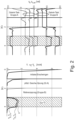
- Fig.6 shows an example of a possible application of the method according to the invention.
- several impedance-based controller modules 102 (modular passive tracking controllers) are integrated into an overall controller 104 by the method according to the invention.
- the representation of the controller modules 102 each includes a reference trajectory and a mass, which are connected to one another via a spring-damper system, whereby the controller modules 102 with the designations A and C each represent a Cartesian control task, while the controller modules 102 with the designations B and D are formulated as joint controllers.
- the various controller modules 102 each of which consists of a task mapping matrix and a task vector, can be combined to form a stack of tasks consisting of a combined task mapping matrix 106 and a combined task vector 110.
- the controller modules represented by the stack of tasks can be merged to form an overall controller 104. In this way, an optimal compromise is achieved between the various sub-controller objectives, with the passivity of the resulting overall controller 104 being implemented in the best possible way.
- MPTC Modular Passive Tracking Controller
- MPTC Modular Passive Tracking Controller
- SoT stack of tasks
- SoT acts as the basis for the synthesis of an overall system controller.
- the corresponding analysis and controller design are based on Lyapunov theory.
- An important contribution of this work is the design of a specific optimization weighting matrix that ensures the passivity of an overdetermined and thus contradictory task setup.
- the proposed framework is validated by simulations and experiments, both for fixed and free-floating robots.
- the present work is inspired by the family of inverse dynamics-based tracking controllers, which softly trade off multiple tasks (combined in a stack of tasks (SoT)) using a single weighted QP [13, 15, 10].
- Such controllers are easy to write and are characterized by their high flexibility.
- these controllers are less robust against modeling errors and contact uncertainties [10, 6] compared to passivity-based approaches such as [19, 5, 12, 16, 6]. This causes problems when implemented on real systems, such as vibrations, which are often addressed by heuristic approaches [13, 10].
- the weight-based multi-objective controller in [3] and the strictly hierarchical passivity-based controller from [6] served as inspiration for this work. Similar to [3], we use a QP to combine individual control objectives from different task space controllers. In [3], however, each individual control objective is calculated based on inverse dynamics with the identity matrix as the desired inertia (feedback linearization). In contrast, the individual task controllers presented here use the concept of passivity and avoid modifying the inertia, i.e., we aim for a PD+-like closed-loop behavior for each individual task [19].
- control architecture based on nominally passive subtask controllers, the so-called Modular Passive Tracking Controllers (MPTC). These are combined and balanced using a stack of tasks, where the stack of tasks is solved by a single weighted pseudo-inverse or a corresponding QP.
- MPTC Modular Passive Tracking Controllers
- the control framework combines the advantages of both inverse dynamics controllers and as well as passivity-based controllers, namely: simplicity of implementation and application, support of task space tracking, passivity and contact robustness, and natural handling of singularities.
- the corresponding stability analysis is based on Lyapunov theory. It is shown that the overall controller is asymptotically stable and passive in the case that the tasks do not contradict each other.
- the paper is structured as follows: Chapter II derives the Modular Passive Tracking Controller (MPTC) at task level, while Chapter III presents the corresponding analysis of the overall closed-loop and the controller derivation. Chapter IV compares MPTC with Inverse Dynamics (ID) and PD+ based controllers, and presents a wide range of possible decoupling characteristics. Chapter V presents simulation results for both fixed-base and free-floating robots, while Chapter VI concludes the paper.
- MPTC Modular Passive Tracking Controller
- the general equation of motion of a robot can be written as where denotes the generalized coordinates 1 , M ( q ), C ( q,q ⁇ ) and ⁇ g ( q ) denote the inertia matrix, Coriolis and centrifugal matrix, and the gravitational torques 2 , and refers to the generalized forces.
- These consist on the one hand of joint motor torques ⁇ j and internal disturbance torques ⁇ int , which act in the robot joints (e.g. joint friction), both of which act on ⁇ via the joint selection matrix S 3 , and on the other hand of external torques ⁇ ext .
- ⁇ k,ref and ⁇ k,ref denote the task reference speed and task reference acceleration.
- the Matrix denotes the dynamically consistent pseudo-inverse of
- MPTC Modular Passive Tracking Controller
- the (actual) task force 5 f k as: 5 Note: Depending on the task, the task force may include linear forces, torques, wrenches, etc.
- equation (20) corresponds to a spring-mass-damper dynamics for task k.
- asymptotic stability of all trajectories can be shown. This can be achieved, for example, by using the ⁇ -method [17] to obtain a strong Lyapunov function with negative definite time derivative, similar to that in [6].
- compliance 7 behavior For example in case of underactuation or other actuator limits, unexpected external disturbances or conflicting tasks, (20) corresponds to a compliance 7 behavior [7]. For such cases, further analysis may be necessary. In this work, we focus on the problem of task inconsistencies, which will be addressed in the following chapters. 7 As a reminder, compliance means an impedance behavior with natural inertia (no modification of the inertia).
- controllers for the entire system consisting of the subtask controllers, that is, for the complete set of desired task forces f k,des from (17) for k ⁇ ⁇ 1,.., n T ⁇ , and we analyze their closed-loop behavior by applying Lyapunov theory.
- Possible controllers can, for example, use pseudo-inverse based optimization as in (36) for unconstrained control problems or Quadratic Programming (QP) based optimization (see Chapter III-E) to handle inequality-based constraints.
- V ⁇ des is negative semi-definite if all ⁇ k > 0, since all desired task Lyapunov function derivatives V ⁇ k,des are negative semi-definite.
- the actual error the total Lyapunov function derivative can be written as follows where Please note that is a function of f ⁇ , and thus also of the actual generalized forces ⁇ .
- W denotes an arbitrary symmetric and positive-definite weight matrix.
- G This cost function G is minimized by the various controllers presented in Chapters III-D and III-E.
- the cost function (34) is minimized by setting (35) to zero and solving for the controller forces ⁇ cmd :
- T ⁇ JM -1 , where ⁇ is a block-diagonal matrix containing the task-space inertia matrices ⁇ M l ,..., M n r ⁇ as diagonal submatrices.
- ⁇ is a block-diagonal matrix containing the task-space inertia matrices ⁇ M l ,..., M n r ⁇ as diagonal submatrices.
- (40) is nonzero, so that from (39) is not equal to zero, even in the regulation case.
- (40) becomes 10 even if W is chosen as a diagonal matrix, as is often found in the Inverse Dynamics (ID) related literature.
- the total weight matrix W ⁇ -1 ⁇ from (41) is symmetric and block-diagonal. Its symmetry property results from the symmetry of its diagonal sub-matrices which are a function of ⁇ k and the inverse of the (symmetric) task inertia matrix M k . When looking at (45), it becomes clear that each task can still be weighted independently (with respect to the other tasks) by its corresponding weight scalar ⁇ k .
- PWOW passivity-guaranteed optimization weight
- Inverse Dynamics (ID) based controllers typically implement a stable second order dynamics of the following form which enables tracking of the reference trajectory x k,ref , ⁇ k,ref , ⁇ k, ref for positive definite proportional and derivative gain matrices P ⁇ ID,k and D ⁇ ID,k .
- the two gain matrices are typically chosen as diagonal matrices in order to to obtain a completely decoupled, linear dynamic. Often the so-called pole placement [1] is used to achieve a critically damped transient response.
- MPTC Modular Passive Tracking Controller
- (52) and (53) are written here in the task acceleration space, in which constant gain matrices result for ID, which correspond to constant system or task eigenvalues, respectively, while the local eigenvalues of MPTC are configuration-dependent. If, however, (52) and (53) are transferred to the task force space by pre-multiplying with M k , it can be seen that the perceived damping and stiffness are constant in the case of MPTC, while they are configuration-dependent for ID.
- N k denotes a null-space projector that removes all components of q ⁇ that would have an effect on the task-space velocity ⁇ k
- the matrix B k combines the corresponding CC-related feedback terms.
- this formulation provides a more direct insight into the CC term truncation strategy of the MPTC controller: MPTC truncates all non-task-related CC feedback terms (comparable to the off-diagonal elements in [7]) and generates a task-related feedforward term C k ⁇ k,rej , while the task-related CC feedback terms are not truncated or used.
- the latter can be verified by considering the nominal subtask closed-loop behavior (20), in which the task-related CC terms remain untouched. Keeping the task-related CC terms is a prerequisite for passivity and leads to a higher robustness against model errors compared to inverse dynamics based controllers. The latter completely truncate all CC effects (based on the potentially inaccurate robot model), while MPTC-based controllers only truncate the non-task-related CC terms.
- MPTC represents a generic controller design tool, both in terms of the choice of sub-controller types (e.g. Cartesian or joint controllers) and in terms of the "granularity" of the desired decoupling 13 .
- sub-controller types e.g. Cartesian or joint controllers
- the "granularity" of the desired decoupling 13 e.g. the number of degrees of freedom assigned to the respective task. This means that there is a multitude of imaginable controller configurations.
- control objectives e.g. a Cartesian end-effector tracking objective and a joint control objective
- SoT stack of tasks
- a six-dimensional Cartesian task can be defined as two decoupled (linear and angular) control subtasks, or alternatively as a single six-dimensional task.
- the linear and angular error dynamics would be decoupled from each other, while in the second case they would be coupled. 13 Note: we are talking about "targeted decoupling" here.
- MPTC results in a strictly decoupled error dynamics.
- a coupling of the corresponding task error dynamics is unavoidable (at least for soft task prioritization).
- FC-PTC Fully Coupled Passive Tracking Controller
- FD-PTC Fully Decoupled Passive Tracking Controller
- FD-PTC is the one that most resembles an Inverse Dynamics controller; both are based on one-degree-of-freedom decoupled task dynamics (see Fig. 1 ). However, it is assumed that FD-PTC has a higher robustness, since the inertia is not modified and fewer CC terms are truncated.
- each task has only a single weight scalar ⁇ k , which allows the tasks to be (softly) prioritized against each other. This reduces the necessary tuning effort.
- a certain task component eg if the z-direction is to be preferred to the x and y components of a Cartesian task
- it must be assigned its own task and a suitable weight (eg ⁇ z ).
- the first simulation presented is intended to investigate the regulation case for a fully actuated, completely determined and thus conflict-free task setup.
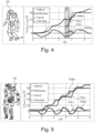
- the six joints of a fixed-base robot arm (whose kinematics and inertia properties correspond to one of TORO's legs) were assigned to two different joint tasks A and B (which each cover three joints, see Fig. 2 ).
- the scalar task weights ⁇ k (here all set to 1) have no effect, since all tasks were perfectly fulfilled anyway due to the lack of conflicts.
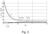
- the second simulation presented evaluates the performance of the controller for a conflicting task setup, again for the regulation case.
- the scalar task weights ⁇ k are set to 1.
- the robot converges to an equilibrium position. Note that the total value of the Lyapunov function V decreases monotonically, while the weighted Lyapunov function values of the sub-tasks can also increase (such as ⁇ j s ⁇ V j s in Fig. 3 ).
- MPTC Modular Passive Tracking Controller
- This generic controller aims in a first step to fulfill several subtask objectives independently of each other. These primarily independent subtask controllers are then merged into an overall controller.
- the design and analysis of the controller are based on the Lyapunov theory, which facilitates statements about stability and passivity.
- One of the main contributions of this paper is the design of an optimization weighting matrix that guarantees the passivity of a complete set of conflicting subtasks for fully actuated robots.
- the proposed control framework was validated in several simulations and experiments for fixed-base and free-floating robots.
Landscapes
- Engineering & Computer Science (AREA)
- Robotics (AREA)
- Mechanical Engineering (AREA)
- Physics & Mathematics (AREA)
- Mathematical Physics (AREA)
- Automation & Control Theory (AREA)
- Feedback Control In General (AREA)
- Manipulator (AREA)
Applications Claiming Priority (2)
| Application Number | Priority Date | Filing Date | Title |
|---|---|---|---|
| DE102020115517 | 2020-06-10 | ||
| PCT/EP2021/065699 WO2021250201A1 (de) | 2020-06-10 | 2021-06-10 | Verfahren und computerprogrammprodukt zum regeln eines roboters |
Publications (3)
| Publication Number | Publication Date |
|---|---|
| EP4164840A1 EP4164840A1 (de) | 2023-04-19 |
| EP4164840B1 true EP4164840B1 (de) | 2024-04-10 |
| EP4164840C0 EP4164840C0 (de) | 2024-04-10 |
Family
ID=76796921
Family Applications (1)
| Application Number | Title | Priority Date | Filing Date |
|---|---|---|---|
| EP21732804.6A Active EP4164840B1 (de) | 2020-06-10 | 2021-06-10 | Verfahren und computerprogrammprodukt zum regeln eines roboters |
Country Status (7)
| Country | Link |
|---|---|
| US (1) | US12280505B2 (cg-RX-API-DMAC7.html) |
| EP (1) | EP4164840B1 (cg-RX-API-DMAC7.html) |
| JP (1) | JP7661370B2 (cg-RX-API-DMAC7.html) |
| KR (1) | KR102747737B1 (cg-RX-API-DMAC7.html) |
| CN (1) | CN116033998B (cg-RX-API-DMAC7.html) |
| DE (1) | DE112021003199B4 (cg-RX-API-DMAC7.html) |
| WO (1) | WO2021250201A1 (cg-RX-API-DMAC7.html) |
Cited By (1)
| Publication number | Priority date | Publication date | Assignee | Title |
|---|---|---|---|---|
| DE102023126559B3 (de) | 2023-09-28 | 2025-03-06 | Deutsches Zentrum für Luft- und Raumfahrt e.V. | Verfahren und System zum Planen und Steuern des Gleichgewichts- und der Fortbewegung eines humanoiden zweibeinigen Roboters |
Families Citing this family (3)
| Publication number | Priority date | Publication date | Assignee | Title |
|---|---|---|---|---|
| CN114347020B (zh) * | 2021-12-22 | 2024-02-13 | 深圳市优必选科技股份有限公司 | 一种运动控制方法、运动控制装置及机器人 |
| CN114932561B (zh) * | 2022-07-26 | 2022-10-14 | 珞石(北京)科技有限公司 | 一种机器人单关节位置控制方法 |
| CN120244946B (zh) * | 2025-03-03 | 2025-11-28 | 烟台大学 | 一种输入约束下机械臂的无源机动数字控制方法 |
Family Cites Families (16)
| Publication number | Priority date | Publication date | Assignee | Title |
|---|---|---|---|---|
| US4999553A (en) | 1989-12-28 | 1991-03-12 | The United States Of America As Represented By The Administrator Of The National Aeronautics And Space Administration | Method and apparatus for configuration control of redundant robots |
| JP3817721B2 (ja) * | 1997-05-23 | 2006-09-06 | 株式会社安川電機 | 冗長自由度マニピュレータのコンプライアンス制御装置 |
| EP1972416B1 (en) * | 2007-03-23 | 2018-04-25 | Honda Research Institute Europe GmbH | Robots with occlusion avoidance functionality |
| US8364314B2 (en) * | 2009-04-30 | 2013-01-29 | GM Global Technology Operations LLC | Method and apparatus for automatic control of a humanoid robot |
| JP5506618B2 (ja) * | 2009-12-28 | 2014-05-28 | 本田技研工業株式会社 | ロボットの制御装置 |
| WO2011106239A1 (en) * | 2010-02-25 | 2011-09-01 | Honda Motor Co., Ltd. | Constrained resolved acceleration control |
| DE102011106321A1 (de) * | 2011-07-01 | 2013-01-03 | Kuka Laboratories Gmbh | Verfahren und Steuermittel zum Steuern eines Roboters |
| FR2978844B1 (fr) | 2011-08-04 | 2014-03-21 | Aldebaran Robotics | Robot a articulations de rigidite variable et methode de calcul de ladite rigidite optimisee |
| US9195794B2 (en) * | 2012-04-10 | 2015-11-24 | Honda Motor Co., Ltd. | Real time posture and movement prediction in execution of operational tasks |
| DE102013010290A1 (de) * | 2013-06-19 | 2014-12-24 | Kuka Laboratories Gmbh | Überwachen eines kinematisch redundanten Roboters |
| JP6500492B2 (ja) | 2015-02-25 | 2019-04-17 | トヨタ自動車株式会社 | ロボット制御装置 |
| DE102015106227B3 (de) * | 2015-04-22 | 2016-05-19 | Deutsches Zentrum für Luft- und Raumfahrt e.V. | Steuern und/oder Regeln von Motoren eines Roboters |
| FR3054048B1 (fr) * | 2016-07-13 | 2018-08-24 | Commissariat Energie Atomique | Procede et systeme de commande hierarchique en temps reel d'une structure articulee exploitant un nombre limite de capteurs de mouvement |
| US11697205B2 (en) | 2017-09-22 | 2023-07-11 | Google Llc | Determining control policies for robots with noise-tolerant structured exploration |
| CN109079780B (zh) | 2018-08-08 | 2020-11-10 | 北京理工大学 | 基于广义坐标的分布式移动机械臂任务分层优化控制方法 |
| IT201900024481A1 (it) * | 2019-12-18 | 2021-06-18 | Fondazione St Italiano Tecnologia | Robot modulare configurabile, procedimento e prodotto informatico corrispondenti |
-
2021
- 2021-06-10 CN CN202180055850.XA patent/CN116033998B/zh active Active
- 2021-06-10 EP EP21732804.6A patent/EP4164840B1/de active Active
- 2021-06-10 US US18/008,760 patent/US12280505B2/en active Active
- 2021-06-10 WO PCT/EP2021/065699 patent/WO2021250201A1/de not_active Ceased
- 2021-06-10 JP JP2022576402A patent/JP7661370B2/ja active Active
- 2021-06-10 DE DE112021003199.6T patent/DE112021003199B4/de active Active
- 2021-06-10 KR KR1020237000885A patent/KR102747737B1/ko active Active
Cited By (1)
| Publication number | Priority date | Publication date | Assignee | Title |
|---|---|---|---|---|
| DE102023126559B3 (de) | 2023-09-28 | 2025-03-06 | Deutsches Zentrum für Luft- und Raumfahrt e.V. | Verfahren und System zum Planen und Steuern des Gleichgewichts- und der Fortbewegung eines humanoiden zweibeinigen Roboters |
Also Published As
| Publication number | Publication date |
|---|---|
| KR102747737B1 (ko) | 2024-12-31 |
| DE112021003199A5 (de) | 2023-05-11 |
| KR20230045006A (ko) | 2023-04-04 |
| US20240261964A1 (en) | 2024-08-08 |
| CN116033998A (zh) | 2023-04-28 |
| EP4164840A1 (de) | 2023-04-19 |
| DE112021003199B4 (de) | 2025-07-10 |
| US12280505B2 (en) | 2025-04-22 |
| WO2021250201A1 (de) | 2021-12-16 |
| JP7661370B2 (ja) | 2025-04-14 |
| CN116033998B (zh) | 2025-06-13 |
| EP4164840C0 (de) | 2024-04-10 |
| JP2023547974A (ja) | 2023-11-15 |
Similar Documents
| Publication | Publication Date | Title |
|---|---|---|
| DE112021003199B4 (de) | Verfahren und Computerprogrammprodukt zum Regeln eines Roboters | |
| DE102020120116B4 (de) | Verfahren zur impedanzbasierten Multi-Tasking Tracking-Regelung, impedanzbasierter Multi-Tasking Tracking-Regler und kraft- und/oder drehmomentgeregelter Roboter | |
| DE102010018440B4 (de) | Hierarchisches Robotersteuerungssystem und -Verfahren zum Steuern ausgewählter Freiheitsgrade eines Objekts unter Verwendung mehrerer Manipulatoren | |
| EP3285975B1 (de) | Steuern und/oder regeln von motoren eines roboters | |
| DE102021112485B3 (de) | Verfahren zur Balancierung eines Roboters, Verfahren zur Ganzkörpersteuerung eines Roboters, Regler sowie Roboter | |
| DE102009058004B4 (de) | Impedanzsteuerung im Betriebsraum mit mehreren Prioritäten | |
| DE102011011681B4 (de) | Roboter mit einer Lernsteuerfunktion | |
| EP2072194B1 (de) | Verfahren und Vorrichtung zur modellbasierten Regelung eines Manipulators | |
| WO2022022784A1 (de) | Verfahren und system zur bestimmung von optimierten programmparametern für ein roboterprogramm | |
| DE102019134665B3 (de) | Kalibrieren eines virtuellen Kraftsensors eines Robotermanipulators | |
| DE102019205651B3 (de) | Verfahren und System zum Ausführen von Roboterapplikationen | |
| DE102014226936B3 (de) | Ganzkörperimpedanz für mobile Roboter | |
| Young et al. | Sliding-mode design for robust linear optimal control | |
| WO2017129352A1 (de) | Verfahren und system zur bahnplanung eines redundanten roboters | |
| DE102018214257B3 (de) | Roboterregelung | |
| EP1612004B1 (de) | Verfahren und Vorrichtung zum Steuern des Handhabungsgeräts | |
| DE102023117136A1 (de) | Prädiktives regelungsverfahren zum regeln der drehmomentänderungsrate und zur schwingungsunterdrückung | |
| DE102018210864B3 (de) | Verfahren und System zum Regeln eines Roboters | |
| EP3328595A2 (de) | Verfahren und system zum steuern eines roboters | |
| DE102020127532B3 (de) | Regelungsverfahren zum Regeln des Drehmoments und/oder der Position mindestens eines elastizitätsbehafteten Gelenks einer Handhabungsvorrichtung, Drehmomentregler, Positionsregler und Verwendung des Verfahrens zur Regelung der Position und/oder des Drehmoments mindestens eines elastizitätsbehafteten Gelenks einer Handhabungsvorrichtung | |
| DE102019201473A1 (de) | Maschinenlernvorrichtung, Servomotor-Steuerung, Servomotorsteuerungssystem und Maschinenlernverfahren | |
| DE102020209866B3 (de) | Verfahren und System zum Betreiben eines Roboters | |
| Toner et al. | Probabilistically safe mobile manipulation in an unmodeled environment with automated feedback tuning | |
| DE102022206381B4 (de) | Verfahren zum Steuern einer Robotervorrichtung | |
| DE102009040194B4 (de) | Verfahren zur Kraftregelung |
Legal Events
| Date | Code | Title | Description |
|---|---|---|---|
| STAA | Information on the status of an ep patent application or granted ep patent |
Free format text: STATUS: UNKNOWN |
|
| STAA | Information on the status of an ep patent application or granted ep patent |
Free format text: STATUS: THE INTERNATIONAL PUBLICATION HAS BEEN MADE |
|
| PUAI | Public reference made under article 153(3) epc to a published international application that has entered the european phase |
Free format text: ORIGINAL CODE: 0009012 |
|
| STAA | Information on the status of an ep patent application or granted ep patent |
Free format text: STATUS: REQUEST FOR EXAMINATION WAS MADE |
|
| 17P | Request for examination filed |
Effective date: 20221221 |
|
| AK | Designated contracting states |
Kind code of ref document: A1 Designated state(s): AL AT BE BG CH CY CZ DE DK EE ES FI FR GB GR HR HU IE IS IT LI LT LU LV MC MK MT NL NO PL PT RO RS SE SI SK SM TR |
|
| DAV | Request for validation of the european patent (deleted) | ||
| DAX | Request for extension of the european patent (deleted) | ||
| GRAP | Despatch of communication of intention to grant a patent |
Free format text: ORIGINAL CODE: EPIDOSNIGR1 |
|
| STAA | Information on the status of an ep patent application or granted ep patent |
Free format text: STATUS: GRANT OF PATENT IS INTENDED |
|
| INTG | Intention to grant announced |
Effective date: 20231116 |
|
| GRAS | Grant fee paid |
Free format text: ORIGINAL CODE: EPIDOSNIGR3 |
|
| GRAA | (expected) grant |
Free format text: ORIGINAL CODE: 0009210 |
|
| STAA | Information on the status of an ep patent application or granted ep patent |
Free format text: STATUS: THE PATENT HAS BEEN GRANTED |
|
| AK | Designated contracting states |
Kind code of ref document: B1 Designated state(s): AL AT BE BG CH CY CZ DE DK EE ES FI FR GB GR HR HU IE IS IT LI LT LU LV MC MK MT NL NO PL PT RO RS SE SI SK SM TR |
|
| REG | Reference to a national code |
Ref country code: GB Ref legal event code: FG4D Free format text: NOT ENGLISH |
|
| REG | Reference to a national code |
Ref country code: CH Ref legal event code: EP |
|
| REG | Reference to a national code |
Ref country code: DE Ref legal event code: R096 Ref document number: 502021003319 Country of ref document: DE |
|
| REG | Reference to a national code |
Ref country code: IE Ref legal event code: FG4D Free format text: LANGUAGE OF EP DOCUMENT: GERMAN |
|
| U01 | Request for unitary effect filed |
Effective date: 20240507 |
|
| U07 | Unitary effect registered |
Designated state(s): AT BE BG DE DK EE FI FR IT LT LU LV MT NL PT SE SI Effective date: 20240516 |
|
| U20 | Renewal fee for the european patent with unitary effect paid |
Year of fee payment: 4 Effective date: 20240515 |
|
| PG25 | Lapsed in a contracting state [announced via postgrant information from national office to epo] |
Ref country code: IS Free format text: LAPSE BECAUSE OF FAILURE TO SUBMIT A TRANSLATION OF THE DESCRIPTION OR TO PAY THE FEE WITHIN THE PRESCRIBED TIME-LIMIT Effective date: 20240810 |
|
| PG25 | Lapsed in a contracting state [announced via postgrant information from national office to epo] |
Ref country code: HR Free format text: LAPSE BECAUSE OF FAILURE TO SUBMIT A TRANSLATION OF THE DESCRIPTION OR TO PAY THE FEE WITHIN THE PRESCRIBED TIME-LIMIT Effective date: 20240410 |
|
| PG25 | Lapsed in a contracting state [announced via postgrant information from national office to epo] |
Ref country code: GR Free format text: LAPSE BECAUSE OF FAILURE TO SUBMIT A TRANSLATION OF THE DESCRIPTION OR TO PAY THE FEE WITHIN THE PRESCRIBED TIME-LIMIT Effective date: 20240711 |
|
| PG25 | Lapsed in a contracting state [announced via postgrant information from national office to epo] |
Ref country code: ES Free format text: LAPSE BECAUSE OF FAILURE TO SUBMIT A TRANSLATION OF THE DESCRIPTION OR TO PAY THE FEE WITHIN THE PRESCRIBED TIME-LIMIT Effective date: 20240410 |
|
| PG25 | Lapsed in a contracting state [announced via postgrant information from national office to epo] |
Ref country code: PL Free format text: LAPSE BECAUSE OF FAILURE TO SUBMIT A TRANSLATION OF THE DESCRIPTION OR TO PAY THE FEE WITHIN THE PRESCRIBED TIME-LIMIT Effective date: 20240410 |
|
| PG25 | Lapsed in a contracting state [announced via postgrant information from national office to epo] |
Ref country code: PL Free format text: LAPSE BECAUSE OF FAILURE TO SUBMIT A TRANSLATION OF THE DESCRIPTION OR TO PAY THE FEE WITHIN THE PRESCRIBED TIME-LIMIT Effective date: 20240410 Ref country code: NO Free format text: LAPSE BECAUSE OF FAILURE TO SUBMIT A TRANSLATION OF THE DESCRIPTION OR TO PAY THE FEE WITHIN THE PRESCRIBED TIME-LIMIT Effective date: 20240710 Ref country code: IS Free format text: LAPSE BECAUSE OF FAILURE TO SUBMIT A TRANSLATION OF THE DESCRIPTION OR TO PAY THE FEE WITHIN THE PRESCRIBED TIME-LIMIT Effective date: 20240810 Ref country code: HR Free format text: LAPSE BECAUSE OF FAILURE TO SUBMIT A TRANSLATION OF THE DESCRIPTION OR TO PAY THE FEE WITHIN THE PRESCRIBED TIME-LIMIT Effective date: 20240410 Ref country code: GR Free format text: LAPSE BECAUSE OF FAILURE TO SUBMIT A TRANSLATION OF THE DESCRIPTION OR TO PAY THE FEE WITHIN THE PRESCRIBED TIME-LIMIT Effective date: 20240711 Ref country code: ES Free format text: LAPSE BECAUSE OF FAILURE TO SUBMIT A TRANSLATION OF THE DESCRIPTION OR TO PAY THE FEE WITHIN THE PRESCRIBED TIME-LIMIT Effective date: 20240410 Ref country code: RS Free format text: LAPSE BECAUSE OF FAILURE TO SUBMIT A TRANSLATION OF THE DESCRIPTION OR TO PAY THE FEE WITHIN THE PRESCRIBED TIME-LIMIT Effective date: 20240710 |
|
| REG | Reference to a national code |
Ref country code: DE Ref legal event code: R097 Ref document number: 502021003319 Country of ref document: DE |
|
| PG25 | Lapsed in a contracting state [announced via postgrant information from national office to epo] |
Ref country code: CZ Free format text: LAPSE BECAUSE OF FAILURE TO SUBMIT A TRANSLATION OF THE DESCRIPTION OR TO PAY THE FEE WITHIN THE PRESCRIBED TIME-LIMIT Effective date: 20240410 |
|
| PG25 | Lapsed in a contracting state [announced via postgrant information from national office to epo] |
Ref country code: SK Free format text: LAPSE BECAUSE OF FAILURE TO SUBMIT A TRANSLATION OF THE DESCRIPTION OR TO PAY THE FEE WITHIN THE PRESCRIBED TIME-LIMIT Effective date: 20240410 Ref country code: RO Free format text: LAPSE BECAUSE OF FAILURE TO SUBMIT A TRANSLATION OF THE DESCRIPTION OR TO PAY THE FEE WITHIN THE PRESCRIBED TIME-LIMIT Effective date: 20240410 |
|
| PG25 | Lapsed in a contracting state [announced via postgrant information from national office to epo] |
Ref country code: SM Free format text: LAPSE BECAUSE OF FAILURE TO SUBMIT A TRANSLATION OF THE DESCRIPTION OR TO PAY THE FEE WITHIN THE PRESCRIBED TIME-LIMIT Effective date: 20240410 |
|
| PG25 | Lapsed in a contracting state [announced via postgrant information from national office to epo] |
Ref country code: SM Free format text: LAPSE BECAUSE OF FAILURE TO SUBMIT A TRANSLATION OF THE DESCRIPTION OR TO PAY THE FEE WITHIN THE PRESCRIBED TIME-LIMIT Effective date: 20240410 Ref country code: SK Free format text: LAPSE BECAUSE OF FAILURE TO SUBMIT A TRANSLATION OF THE DESCRIPTION OR TO PAY THE FEE WITHIN THE PRESCRIBED TIME-LIMIT Effective date: 20240410 Ref country code: RO Free format text: LAPSE BECAUSE OF FAILURE TO SUBMIT A TRANSLATION OF THE DESCRIPTION OR TO PAY THE FEE WITHIN THE PRESCRIBED TIME-LIMIT Effective date: 20240410 Ref country code: CZ Free format text: LAPSE BECAUSE OF FAILURE TO SUBMIT A TRANSLATION OF THE DESCRIPTION OR TO PAY THE FEE WITHIN THE PRESCRIBED TIME-LIMIT Effective date: 20240410 Ref country code: MC Free format text: LAPSE BECAUSE OF FAILURE TO SUBMIT A TRANSLATION OF THE DESCRIPTION OR TO PAY THE FEE WITHIN THE PRESCRIBED TIME-LIMIT Effective date: 20240410 |
|
| REG | Reference to a national code |
Ref country code: CH Ref legal event code: PL |
|
| PLBE | No opposition filed within time limit |
Free format text: ORIGINAL CODE: 0009261 |
|
| STAA | Information on the status of an ep patent application or granted ep patent |
Free format text: STATUS: NO OPPOSITION FILED WITHIN TIME LIMIT |
|
| 26N | No opposition filed |
Effective date: 20250113 |
|
| PG25 | Lapsed in a contracting state [announced via postgrant information from national office to epo] |
Ref country code: IE Free format text: LAPSE BECAUSE OF NON-PAYMENT OF DUE FEES Effective date: 20240610 |
|
| PG25 | Lapsed in a contracting state [announced via postgrant information from national office to epo] |
Ref country code: CH Free format text: LAPSE BECAUSE OF NON-PAYMENT OF DUE FEES Effective date: 20240630 |
|
| U20 | Renewal fee for the european patent with unitary effect paid |
Year of fee payment: 5 Effective date: 20250512 |
|
| PG25 | Lapsed in a contracting state [announced via postgrant information from national office to epo] |
Ref country code: CY Free format text: LAPSE BECAUSE OF FAILURE TO SUBMIT A TRANSLATION OF THE DESCRIPTION OR TO PAY THE FEE WITHIN THE PRESCRIBED TIME-LIMIT; INVALID AB INITIO Effective date: 20210610 |
|
| GBPC | Gb: european patent ceased through non-payment of renewal fee |
Effective date: 20250610 |
|
| PG25 | Lapsed in a contracting state [announced via postgrant information from national office to epo] |
Ref country code: HU Free format text: LAPSE BECAUSE OF FAILURE TO SUBMIT A TRANSLATION OF THE DESCRIPTION OR TO PAY THE FEE WITHIN THE PRESCRIBED TIME-LIMIT; INVALID AB INITIO Effective date: 20210610 |
|
| PG25 | Lapsed in a contracting state [announced via postgrant information from national office to epo] |
Ref country code: GB Free format text: LAPSE BECAUSE OF NON-PAYMENT OF DUE FEES Effective date: 20250610 |
|
| PG25 | Lapsed in a contracting state [announced via postgrant information from national office to epo] |
Ref country code: TR Free format text: LAPSE BECAUSE OF FAILURE TO SUBMIT A TRANSLATION OF THE DESCRIPTION OR TO PAY THE FEE WITHIN THE PRESCRIBED TIME-LIMIT Effective date: 20240410 |
|
| U20 | Renewal fee for the european patent with unitary effect paid |
Year of fee payment: 6 Effective date: 20260513 |