EP4163508B1 - Slide bearing and method of producing the same - Google Patents
Slide bearing and method of producing the same Download PDFInfo
- Publication number
- EP4163508B1 EP4163508B1 EP22195324.3A EP22195324A EP4163508B1 EP 4163508 B1 EP4163508 B1 EP 4163508B1 EP 22195324 A EP22195324 A EP 22195324A EP 4163508 B1 EP4163508 B1 EP 4163508B1
- Authority
- EP
- European Patent Office
- Prior art keywords
- layer
- metal
- slide bearing
- intermetallic compound
- layers
- Prior art date
- Legal status (The legal status is an assumption and is not a legal conclusion. Google has not performed a legal analysis and makes no representation as to the accuracy of the status listed.)
- Active
Links
Images

Classifications
-
- F—MECHANICAL ENGINEERING; LIGHTING; HEATING; WEAPONS; BLASTING
- F16—ENGINEERING ELEMENTS AND UNITS; GENERAL MEASURES FOR PRODUCING AND MAINTAINING EFFECTIVE FUNCTIONING OF MACHINES OR INSTALLATIONS; THERMAL INSULATION IN GENERAL
- F16C—SHAFTS; FLEXIBLE SHAFTS; ELEMENTS OR CRANKSHAFT MECHANISMS; ROTARY BODIES OTHER THAN GEARING ELEMENTS; BEARINGS
- F16C33/00—Parts of bearings; Special methods for making bearings or parts thereof
- F16C33/02—Parts of sliding-contact bearings
- F16C33/04—Brasses; Bushes; Linings
- F16C33/06—Sliding surface mainly made of metal
- F16C33/12—Structural composition; Use of special materials or surface treatments, e.g. for rust-proofing
- F16C33/122—Multilayer structures of sleeves, washers or liners
-
- F—MECHANICAL ENGINEERING; LIGHTING; HEATING; WEAPONS; BLASTING
- F16—ENGINEERING ELEMENTS AND UNITS; GENERAL MEASURES FOR PRODUCING AND MAINTAINING EFFECTIVE FUNCTIONING OF MACHINES OR INSTALLATIONS; THERMAL INSULATION IN GENERAL
- F16C—SHAFTS; FLEXIBLE SHAFTS; ELEMENTS OR CRANKSHAFT MECHANISMS; ROTARY BODIES OTHER THAN GEARING ELEMENTS; BEARINGS
- F16C33/00—Parts of bearings; Special methods for making bearings or parts thereof
- F16C33/02—Parts of sliding-contact bearings
- F16C33/04—Brasses; Bushes; Linings
- F16C33/06—Sliding surface mainly made of metal
- F16C33/12—Structural composition; Use of special materials or surface treatments, e.g. for rust-proofing
- F16C33/122—Multilayer structures of sleeves, washers or liners
- F16C33/127—Details of intermediate layers, e.g. nickel dams
-
- F—MECHANICAL ENGINEERING; LIGHTING; HEATING; WEAPONS; BLASTING
- F16—ENGINEERING ELEMENTS AND UNITS; GENERAL MEASURES FOR PRODUCING AND MAINTAINING EFFECTIVE FUNCTIONING OF MACHINES OR INSTALLATIONS; THERMAL INSULATION IN GENERAL
- F16C—SHAFTS; FLEXIBLE SHAFTS; ELEMENTS OR CRANKSHAFT MECHANISMS; ROTARY BODIES OTHER THAN GEARING ELEMENTS; BEARINGS
- F16C33/00—Parts of bearings; Special methods for making bearings or parts thereof
- F16C33/02—Parts of sliding-contact bearings
- F16C33/04—Brasses; Bushes; Linings
- F16C33/06—Sliding surface mainly made of metal
- F16C33/14—Special methods of manufacture; Running-in
-
- F—MECHANICAL ENGINEERING; LIGHTING; HEATING; WEAPONS; BLASTING
- F16—ENGINEERING ELEMENTS AND UNITS; GENERAL MEASURES FOR PRODUCING AND MAINTAINING EFFECTIVE FUNCTIONING OF MACHINES OR INSTALLATIONS; THERMAL INSULATION IN GENERAL
- F16C—SHAFTS; FLEXIBLE SHAFTS; ELEMENTS OR CRANKSHAFT MECHANISMS; ROTARY BODIES OTHER THAN GEARING ELEMENTS; BEARINGS
- F16C9/00—Bearings for crankshafts or connecting-rods; Attachment of connecting-rods
- F16C9/04—Connecting-rod bearings; Attachments thereof
-
- F—MECHANICAL ENGINEERING; LIGHTING; HEATING; WEAPONS; BLASTING
- F16—ENGINEERING ELEMENTS AND UNITS; GENERAL MEASURES FOR PRODUCING AND MAINTAINING EFFECTIVE FUNCTIONING OF MACHINES OR INSTALLATIONS; THERMAL INSULATION IN GENERAL
- F16C—SHAFTS; FLEXIBLE SHAFTS; ELEMENTS OR CRANKSHAFT MECHANISMS; ROTARY BODIES OTHER THAN GEARING ELEMENTS; BEARINGS
- F16C17/00—Sliding-contact bearings for exclusively rotary movement
- F16C17/02—Sliding-contact bearings for exclusively rotary movement for radial load only
-
- F—MECHANICAL ENGINEERING; LIGHTING; HEATING; WEAPONS; BLASTING
- F16—ENGINEERING ELEMENTS AND UNITS; GENERAL MEASURES FOR PRODUCING AND MAINTAINING EFFECTIVE FUNCTIONING OF MACHINES OR INSTALLATIONS; THERMAL INSULATION IN GENERAL
- F16C—SHAFTS; FLEXIBLE SHAFTS; ELEMENTS OR CRANKSHAFT MECHANISMS; ROTARY BODIES OTHER THAN GEARING ELEMENTS; BEARINGS
- F16C2204/00—Metallic materials; Alloys
- F16C2204/30—Alloys based on one of tin, lead, antimony, bismuth, indium, e.g. materials for providing sliding surfaces
- F16C2204/34—Alloys based on tin
-
- F—MECHANICAL ENGINEERING; LIGHTING; HEATING; WEAPONS; BLASTING
- F16—ENGINEERING ELEMENTS AND UNITS; GENERAL MEASURES FOR PRODUCING AND MAINTAINING EFFECTIVE FUNCTIONING OF MACHINES OR INSTALLATIONS; THERMAL INSULATION IN GENERAL
- F16C—SHAFTS; FLEXIBLE SHAFTS; ELEMENTS OR CRANKSHAFT MECHANISMS; ROTARY BODIES OTHER THAN GEARING ELEMENTS; BEARINGS
- F16C2204/00—Metallic materials; Alloys
- F16C2204/52—Alloys based on nickel, e.g. Inconel
-
- F—MECHANICAL ENGINEERING; LIGHTING; HEATING; WEAPONS; BLASTING
- F16—ENGINEERING ELEMENTS AND UNITS; GENERAL MEASURES FOR PRODUCING AND MAINTAINING EFFECTIVE FUNCTIONING OF MACHINES OR INSTALLATIONS; THERMAL INSULATION IN GENERAL
- F16C—SHAFTS; FLEXIBLE SHAFTS; ELEMENTS OR CRANKSHAFT MECHANISMS; ROTARY BODIES OTHER THAN GEARING ELEMENTS; BEARINGS
- F16C2240/00—Specified values or numerical ranges of parameters; Relations between them
- F16C2240/06—Temperature
-
- F—MECHANICAL ENGINEERING; LIGHTING; HEATING; WEAPONS; BLASTING
- F16—ENGINEERING ELEMENTS AND UNITS; GENERAL MEASURES FOR PRODUCING AND MAINTAINING EFFECTIVE FUNCTIONING OF MACHINES OR INSTALLATIONS; THERMAL INSULATION IN GENERAL
- F16C—SHAFTS; FLEXIBLE SHAFTS; ELEMENTS OR CRANKSHAFT MECHANISMS; ROTARY BODIES OTHER THAN GEARING ELEMENTS; BEARINGS
- F16C2240/00—Specified values or numerical ranges of parameters; Relations between them
- F16C2240/08—Time
-
- F—MECHANICAL ENGINEERING; LIGHTING; HEATING; WEAPONS; BLASTING
- F16—ENGINEERING ELEMENTS AND UNITS; GENERAL MEASURES FOR PRODUCING AND MAINTAINING EFFECTIVE FUNCTIONING OF MACHINES OR INSTALLATIONS; THERMAL INSULATION IN GENERAL
- F16C—SHAFTS; FLEXIBLE SHAFTS; ELEMENTS OR CRANKSHAFT MECHANISMS; ROTARY BODIES OTHER THAN GEARING ELEMENTS; BEARINGS
- F16C2240/00—Specified values or numerical ranges of parameters; Relations between them
- F16C2240/40—Linear dimensions, e.g. length, radius, thickness, gap
- F16C2240/60—Thickness, e.g. thickness of coatings
-
- F—MECHANICAL ENGINEERING; LIGHTING; HEATING; WEAPONS; BLASTING
- F16—ENGINEERING ELEMENTS AND UNITS; GENERAL MEASURES FOR PRODUCING AND MAINTAINING EFFECTIVE FUNCTIONING OF MACHINES OR INSTALLATIONS; THERMAL INSULATION IN GENERAL
- F16C—SHAFTS; FLEXIBLE SHAFTS; ELEMENTS OR CRANKSHAFT MECHANISMS; ROTARY BODIES OTHER THAN GEARING ELEMENTS; BEARINGS
- F16C2240/00—Specified values or numerical ranges of parameters; Relations between them
- F16C2240/90—Surface areas
-
- F—MECHANICAL ENGINEERING; LIGHTING; HEATING; WEAPONS; BLASTING
- F16—ENGINEERING ELEMENTS AND UNITS; GENERAL MEASURES FOR PRODUCING AND MAINTAINING EFFECTIVE FUNCTIONING OF MACHINES OR INSTALLATIONS; THERMAL INSULATION IN GENERAL
- F16C—SHAFTS; FLEXIBLE SHAFTS; ELEMENTS OR CRANKSHAFT MECHANISMS; ROTARY BODIES OTHER THAN GEARING ELEMENTS; BEARINGS
- F16C2360/00—Engines or pumps
- F16C2360/22—Internal combustion engines
-
- F—MECHANICAL ENGINEERING; LIGHTING; HEATING; WEAPONS; BLASTING
- F16—ENGINEERING ELEMENTS AND UNITS; GENERAL MEASURES FOR PRODUCING AND MAINTAINING EFFECTIVE FUNCTIONING OF MACHINES OR INSTALLATIONS; THERMAL INSULATION IN GENERAL
- F16C—SHAFTS; FLEXIBLE SHAFTS; ELEMENTS OR CRANKSHAFT MECHANISMS; ROTARY BODIES OTHER THAN GEARING ELEMENTS; BEARINGS
- F16C2360/00—Engines or pumps
- F16C2360/42—Pumps with cylinders or pistons
-
- F—MECHANICAL ENGINEERING; LIGHTING; HEATING; WEAPONS; BLASTING
- F16—ENGINEERING ELEMENTS AND UNITS; GENERAL MEASURES FOR PRODUCING AND MAINTAINING EFFECTIVE FUNCTIONING OF MACHINES OR INSTALLATIONS; THERMAL INSULATION IN GENERAL
- F16C—SHAFTS; FLEXIBLE SHAFTS; ELEMENTS OR CRANKSHAFT MECHANISMS; ROTARY BODIES OTHER THAN GEARING ELEMENTS; BEARINGS
- F16C33/00—Parts of bearings; Special methods for making bearings or parts thereof
- F16C33/02—Parts of sliding-contact bearings
- F16C33/04—Brasses; Bushes; Linings
- F16C33/06—Sliding surface mainly made of metal
- F16C33/12—Structural composition; Use of special materials or surface treatments, e.g. for rust-proofing
- F16C33/122—Multilayer structures of sleeves, washers or liners
- F16C33/124—Details of overlays
-
- F—MECHANICAL ENGINEERING; LIGHTING; HEATING; WEAPONS; BLASTING
- F16—ENGINEERING ELEMENTS AND UNITS; GENERAL MEASURES FOR PRODUCING AND MAINTAINING EFFECTIVE FUNCTIONING OF MACHINES OR INSTALLATIONS; THERMAL INSULATION IN GENERAL
- F16C—SHAFTS; FLEXIBLE SHAFTS; ELEMENTS OR CRANKSHAFT MECHANISMS; ROTARY BODIES OTHER THAN GEARING ELEMENTS; BEARINGS
- F16C33/00—Parts of bearings; Special methods for making bearings or parts thereof
- F16C33/02—Parts of sliding-contact bearings
- F16C33/04—Brasses; Bushes; Linings
- F16C33/06—Sliding surface mainly made of metal
- F16C33/12—Structural composition; Use of special materials or surface treatments, e.g. for rust-proofing
- F16C33/122—Multilayer structures of sleeves, washers or liners
- F16C33/125—Details of bearing layers, i.e. the lining
Definitions
- the present invention relates to a coating structure of a slide bearing, particularly used in an internal combustion engine, a piston compressor or the like.
- the present invention relates to a slide bearing having a coating structure exhibiting high seizure resistance when an abnormal load is applied to the slide bearing.
- the present invention also relates to a method of manufacturing the slide bearing.
- sliding members such as plain bearings for internal combustion engines include a copper or aluminum lining alloy bonded to a steel back metal.
- the copper alloy or the aluminum alloy allows the sliding members to have a strong surface that can withstand a load applied to the sliding members in use.
- Such sliding members are required to have not only good embedding properties and conformability but also appropriate seizure resistance.
- a soft coating layer is typically provided on a lining layer (bearing alloy layer) in the sliding members.
- JP 2002-310158A describes a multilayer sliding material in which a tin-based overlay layer including a tin-copper-based alloy is provided on a bearing alloy layer via an intermediate layer for preventing diffusion of copper.
- the overlay layer is composed of a plurality of layers including different amounts of copper, thereby allowing the sliding material to maintain seizure resistance.
- JP H11-182549A discloses a slide bearing in which 0.3 to 25 volume % of hard particles having an average grain size of not more than 15 ⁇ m are dispersed in a main load portion of an overlay, thereby achieving high wear resistance and less occurrence of seizure.
- a slide bearing including a base layer and a coating layer.
- the coating layer of the slide bearing is composed of at least two overlay layers and at least one intermediate layer (intermetallic compound containing layer), each located between adjacent ones of the at least two overlay layers.
- the overlay layers and the intermediate layer or layers are laminated in a thickness direction of the coating layer.
- the intermediate layer includes a layered metal portion in an intermetallic compound matrix. An area of the layered metal portion is 60% to 95% of an area of the intermediate layer.
- the coating layer is composed of two overlay layers and an intermediate layer located between the two overlay layers.
- the overlay layers include a Sn-Cu alloy, while the intermetallic compound layer includes a Sn-Ni intermetallic compound and a Sn-Ni-Cu intermetallic compound, and the metal portion includes metal Ni.
- the Sn-Ni intermetallic compound is Ni 3 Sn 4
- the Sn-Ni-Cu intermetallic compound is Sn 5 (CuNi) 6 .
- the intermediate layer has a thickness of 1 to 10 ⁇ m, preferably 2 to 5 ⁇ m.
- the overlay layers each have a thickness of 1 to 30 ⁇ m, preferably 5 to 20 ⁇ m.
- the base layer includes a back-metal layer and a lining layer bonded to the back-metal layer, and the coating layer is located on the lining layer.
- the lining layer is preferably composed of a copper-based alloy or an aluminum-based alloy.
- the slide bearing further includes a dam layer between the lining layer and the coating layer.
- the dam layer preferably includes at least one selected from the group consisting of nickel, cobalt, iron, copper, chromium, zinc, aluminum, and alloys thereof.
- the dam layer has a thickness of 0.5 to 10 ⁇ m, preferably 1 to 6 ⁇ m.
- the coating layer has a total thickness of 5 to 50 ⁇ m.
- a method of manufacturing the above slide bearing includes a step of preparing the base layer, a step of applying a first layer composed of a first metal or a first alloy onto the base layer, a step of applying a second layer composed of a second metal or a second alloy onto the first layer, a step of applying another first layer composed of the first metal or the first alloy onto the second layer, optionally a step of applying at least one set of further second layer composed of the second metal or the second alloy and further first layer composed of the first metal or the first alloy onto the other first layer, and a heat treatment step.
- the stacked layers are heated at a temperature that allows diffusion of metal atoms of the first layers, so that the metal atoms of the first layers diffuse into the second layer to form an intermetallic compound in the second metal or the second alloy while a part of the second metal or the second alloy remains in a metallic state.
- the base layer includes a back-metal layer and a lining layer bonded to the back-metal layer.
- the method further includes a step of applying a dam layer onto the lining layer.
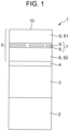
- Fig. 1 is a schematic diagram of a cross-sectional structure of an example of a slide bearing 1 of the present invention.
- the slide bearing 1 includes a base layer composed of a back metal 2 and a lining layer (bearing alloy layer) 3 bonded to the back metal, optionally a dam layer (diffusion blocking layer) 4 applied on the lining layer, and a coating layer 5 applied on the dam layer.
- the coating layer 5 has a structure in which a first overlay layer 61, an intermediate layer 7, and a second overlay layer 62 are laminated. A surface of the first overlay layer 61 constitutes a sliding surface 10.
- the intermediate layer 7 includes a metal portion 9 composed of a metal in an intermetallic compound matrix 8 composed of an intermetallic compound.
- the metal portion 9 extends substantially parallel to the sliding surface 10 in a layered manner, and is divided by the intermetallic compound matrix 8.
- An area of the layered metal portion 9 is 60% to 95% of an area of the intermediate layer 7.
- the area of the layered metal portion 9 is 70% to 90% of the area of the intermediate layer 7.
- the back metal 2 may be composed of any appropriate material such as steel, bronze, or an aluminum alloy.
- the lining layer 3 may be composed of any appropriate material. In practice, it is composed of a copper alloy or an aluminum alloy.
- the dam layer 4 includes at least one selected from the group consisting of nickel, cobalt, iron, copper, chromium, zinc, aluminum, and alloys thereof, and is applied onto the lining layer by a conventional coating method.
- the dam layer is preferably composed of nickel.
- the dam layer may not necessarily include or be composed of a metal or an alloy, and may include or be composed of an intermetallic compound. In the case where an intermetallic compound is formed by heat treatment (described later), the dam layer may have a multilayer structure such as a two-layer structure including a layer composed of a metal or an alloy and an intermetallic compound layer.
- the dam layer 4 typically has a thickness in a range of 0.5 to 10 ⁇ m, and preferably in a range of 1 to 6 ⁇ m.
- the thickness of the dam layer 4 is determined according to its purpose. For example, when the dam layer 4 has a large thickness, the slide bearing can have a good bearing alloy function, and when the dam layer 4 has a small thickness, the slide bearing can have good conformability even when the coating layer 5 is worn.
- the coating layer 5 has a structure in which the first overlay layer 61, the intermediate layer 7, and the second overlay layer 62 are laminated.
- the coating layer 5 may include three or more overlay layers, and include intermediate layers between the overlay layers.
- Fig. 2 is a schematic diagram of a cross-sectional structure of another example of the slide bearing 1 in which a coating layer 5' includes three overlay layers 61', 62', and 63' and two intermediate layers 71 and 72.
- the slide bearing 1 in addition to the coating layer 5', includes the back metal 2, the lining layer 3, and the dam layer 4 as described above.
- a coating layer including four or more overlay layers is also included in the scope of the present invention.
- the plurality of overlay layers 6 of the coating layer 5 may have the same composition or different compositions.
- the overlay layers 6 may include at least one of tin, bismuth, lead, silver, indium, gold, antimony, aluminum, and alloys thereof.
- the overlay layers 6 can be applied by a conventional coating method.
- the overlay layers 6 may include one or more kinds of soft particles selected from the group consisting of PTFE particles, fluorinated polymer particles, metal sulfide particles, metal fluoride particles, metal sulfate particles, graphite particles, other soft carbonaceous particles, hexagonal boron nitride particles, layered silicate particles, titanium oxide particles, zinc oxide particles, lead oxide particles, and other particles having a hexagonal crystal structure.
- the overlay layers 6 may include one or more kinds of hard particles selected from the group consisting of metal oxide particles, boride particles, carbide particles, nitride particles, sulfate particles, silicide particles, diamond particles, carbon nanotube particles, graphene particles, other hard carbonaceous particles, and other particles having a cubic crystal structure.
- the intermetallic compound matrices 8 in the intermediate layers 7 may have the same composition or different compositions, and the metal portions 9 may have the same composition or different compositions.
- the intermetallic compound matrices 8 can be formed by applying a metal layer onto the overlay layers 6 by a conventional coating method, followed by heat treatment.
- the intermetallic compound matrices 8 are required to include at least two elements.
- One of the at least two elements is selected from the group consisting of tin, bismuth, lead, silver, indium, gold, antimony, and aluminum, and the other one or more elements may be selected from the group consisting of nickel, cobalt, zinc, silver, iron, copper, chromium, cadmium, and aluminum.
- the intermetallic compound matrix 8 and/or the metal portion 9 may include one or more kinds of soft particles selected from the group consisting of PTFE particles, fluorinated polymer particles, metal sulfide particles, metal fluoride particles, metal sulfate particles, graphite particles, other soft carbonaceous particles, hexagonal boron nitride particles, layered silicate particles, titanium oxide particles, zinc oxide particles, lead oxide particles, and other particles having a hexagonal crystal structure.
- soft particles selected from the group consisting of PTFE particles, fluorinated polymer particles, metal sulfide particles, metal fluoride particles, metal sulfate particles, graphite particles, other soft carbonaceous particles, hexagonal boron nitride particles, layered silicate particles, titanium oxide particles, zinc oxide particles, lead oxide particles, and other particles having a hexagonal crystal structure.
- the intermetallic compound matrix 8 and/or the metal portion 9 may include one or more kinds of hard particles selected from the group consisting of metal oxide particles, boride particles, carbide particles, nitride particles, sulfate particles, silicide particles, diamond particles, carbon nanotube particles, graphene particles, other hard carbonaceous particles, and other particles having a cubic crystal structure.
- the metal portion 9 in the intermediate layer 7 of the coating layer 5 may be composed of a material selected from nickel, cobalt, zinc, silver, iron, copper, chromium, cadmium, aluminum, and the like.
- the metal portion may be composed of a pure metal or an alloy.
- the metal portion 9 extends substantially parallel to the sliding surface 10 to form a layer or a thin piece, and is divided by the intermetallic compound matrix.
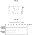
- Fig. 3 is a schematic diagram showing the metal portion 9 extending in a direction parallel to the sliding surface 10. Portions of the layered metal portion 9 are not substantially overlapped in a direction perpendicular to the sliding surface 10.
- the area of the layered metal portion 9 is 60% to 95% of the area of the intermediate layer 7, and preferably 70% to 90%.
- the area of the layered metal portion 9 indicates the area of the metal portion 9 projected on the sliding surface 10 when an image of the metal portion 9 is projected on the sliding surface 10.
- the area of the intermediate layer 7 is equal to the area of the sliding surface (the area ratio of the layered metal portion 9 to the intermediate layer 7 is measured by cross-sectional observation as described below).
- the area ratio of the layered metal portion 9 to the intermediate layer 7 is determined by observing a cross-section of the slide bearing using an optical microscope or a scanning electron microscope (SEM) to measure the length of the metal portion 9 in a direction parallel to the sliding surface 10, and obtaining the ratio of the length of the metal portion 9 to the length of the intermediate layer 7. The obtained ratio is equal to the area ratio of the layered metal portion 9 to the intermediate layer 7.
- the coating layer 5 has a multilayer structure.
- the intermediate layer 7 is divided due to the load, and this achieves high seizure resistance.
- the intermetallic compound protects the layers under the uppermost overlay layer from wear and seizure. At that time, cracking presumably occurs at portions of the intermetallic compound at which the metal portion 9 is divided.
- the entire intermediate layer is not simultaneously peeled off, but only part of the intermediate layer is peeled off.
- the portion of the intermetallic compound at which the metal portion 9 is divided can be controlled by adjusting heat treatment time for a product, and this makes it possible to control the size of portions into which the intermetallic compound is divided.
- the size of the portions into which the intermetallic compound is divided can be controlled appropriately according to the thickness and material of the overlay layers 6, the number of overlay layers 6, and the like.
- the appropriate size of the portions into which the intermetallic compound is divided is preferably 0.1 to 30 ⁇ m, and more preferably 1 to 20 ⁇ m.
- the metal portion 9 provided in a discontinuous manner allows, in any case, that portions of the intermetallic compound matrix 8 and portions of the metal portion 9 are alternately arranged, thus enabling the slide bearing to exhibit high seizure resistance when an abnormal load is applied to the slide bearing.
- the coating layer 5 has a laminated multilayer coating structure composed of the thin layers, i.e., the overlay layers 6 and the intermediate layer 7 including the intermetallic compound matrix 8 and the metal portion 9.
- the laminated coating structure allows the coating layer 5 to have the layers with a small thickness while maintaining the total thickness of the coating layer 5 equivalent to the thickness of a single layer. This achieves much less accumulation of plastic deformation under external loading, and thus allows the coating to have better fatigue performance.
- the intermediate layer 7 has a thickness in a range of 1 to 10 ⁇ m, and preferably in a range of 2 to 5 ⁇ m. Such a structure allows the intermediate layer 7 to include the best metal portion 9, thus enabling the bearing to have high seizure resistance.
- the metal portion 9 preferably has a thickness of 0. 1 to 0.5 ⁇ m in order to achieve the above effect.
- the metal portion 9 having an excessively large thickness leads to a small amount of intermetallic compound, and the above effect is less likely to be obtained.
- the thickness of the metal portion 9 is preferably not more than 30% of the thickness of the intermediate layer 7.
- the overlay layers 6 each have a thickness in the range of 1 to 30 ⁇ m, and preferably in the range of 5 to 20 ⁇ m.
- the thickness of the overlay layers 6 is determined according to the purpose. For example, when an overlay layer 6 has a large thickness, the slide bearing has good conformability and foreign matter embedding properties on the sliding surface. When an overlay layer 6 has a small thickness, the slide bearing has high fatigue resistance on the sliding surface. When all the overlay layers 6 have a large thickness, the slide bearing has extremely good conformability and foreign matter embedding properties. When all the overlay layers 6 have a small thickness, the slide bearing has extremely high fatigue resistance.
- the multilayer structure of the coating layer 5 ensures the thickness of the coating layer 5 as a whole, and this allows the slide bearing to continuously have good conformability and foreign matter embedding properties.
- a base layer (preferably a back-metal layer to which a lining layer is bonded) is prepared.
- a dam layer is optionally applied onto the base layer.
- a first layer composed of a first metal or a first alloy is applied onto the dam layer.
- a second layer composed of a second metal or a second alloy is applied onto the first layer, and another first layer composed of the first metal or the first alloy is applied onto the second layer.
- one or more sets of further second layer composed of the second metal or the second alloy and further first layer composed of the first metal or the first alloy are applied.
- the layers may be applied to each other by a conventional method such as plating or PVD.
- the member is heat treated.
- the intermetallic compound described above is formed by the heat treatment.
- the heat treatment causes metal atoms of the first layers to be diffused and reacted in the second layer to form an intermetallic compound.
- the heat treatment temperature and time are adjusted so that the second metal or the second alloy is not completely converted into an intermetallic compound but remains in a layered manner such that the area ratio (defined above) of the second metal or the second alloy is 60% to 95%.
- the heat treatment is advantageously performed at a temperature of 100°C to 250°C, and preferably at 150°C to 180°C. If the thermal diffusion temperature is higher than the above range, the crystal structure of the overlay layers may be changed and affect the tribological properties of the overlay layers. If the thermal diffusion temperature is lower than the above range, a long treatment time is required, leading to high manufacturing cost.
- the time for the thermal diffusion process is adjusted according to the configuration of the coating, but is advantageously 2 hours to 60 hours, and preferably 12 hours to 36 hours.
- the manufacturing method using thermal diffusion can avoid complicated chemical process management and reduce the harmful internal stress, thus achieving better quality control and product performance.
- Ni was divided, but a layered Ni portion having a maximum thickness of approximately 0.5 ⁇ m remained. The area ratio of the Ni layer was approximately 80%.
- Table 2 shows the thicknesses of the layers after the heat treatment.
- Components Thickness after heat treatment First overlay layer SnCu3 9 ⁇ m Intermetallic compound layer7 (Metal portion9) Sn 5 (CuNi) 6 +Ni 3 Sn 4 (Ni) 3 ⁇ m (0.1 ⁇ 0.5 ⁇ m) Second overlay layer SnCu3 9 ⁇ m Dam layer Ni,Sn 5 (CuNi) 6 +Ni 3 Sn 4 2 ⁇ m Lining layer CuPb22Sn 0.3mm
- An example sample of the present invention having the structure shown in Table 2 was subjected to a seizure test to examine seizure resistance of the sample.
- a seizure test to examine seizure resistance of the sample.
- CuPb22Sn (a lining layer) with a thickness 0.3 mm
- Ni (a dam layer) with a thickness 2 ⁇ m
- SnCu3 (a coating layer) with a thickness 20 ⁇ m were sequentially applied onto a steel back metal with a thickness 0.7 mm, by plating or the like.
- the comparison sample differed in configuration from the sample of the present invention in that the coating layer of the comparison sample was a single layer composed of a Sn-Cu alloy.
- the seizure test was performed using a ring-on-disk tester under oil starvation conditions. Table 3 shows the test conditions. The test was performed by the following method.
- a flat test sample having a test portion with an outer diameter of ⁇ 27 mm and an inner diameter of ⁇ 22 mm was prepared and placed under an annular counter member to be rotated.
- the test sample On the back side of the test sample, the test sample had a lubrication oil filler opening from which lubrication oil was supplied.
- a hydraulic device was provided on the underside of the test sample to apply hydraulic pressure to the counter member and to measure the friction torque and the back surface temperature of the test sample.
- the counter member was rotated without applying pressure, and the rotational speed was gradually increased.
- the peripheral speed of the counter member reached 2 m/s and the back surface temperature of the sample reached 130°C
- the test load was increased to 10 MPa at a pace of 2 MPa every 2 minutes.
- the load applied to the test sample by the counter member reached 10 MPa
- the supply of lubrication oil was stopped and the test was started.
- the friction torque exceeded 5 Nm or the back surface temperature exceeded 200°C, it was determined that seizure occurred in the sample.
- Fig. 4 shows the results of the seizure test.
- seizure occurred in approximately 40 minutes to 75 minutes, and in the slide bearing of the present invention, seizure occurred in 103 minutes to 140 minutes.
- Test sample shape and test portion Flat Test portion: annular shape with outer diameter of ⁇ 27 mm and inner diameter of ⁇ 22 mm Test load 10MPa Peripheral speed 2m/s Lubrication oil SAE 10 Back surface temperature of test sample 130°C Material of counter member S55C Hardness of counter member 500 ⁇ 600 Hv10 Roughness of counter member Ra ⁇ 0.1 ⁇ m Maximum test time 200min
Landscapes
- Engineering & Computer Science (AREA)
- General Engineering & Computer Science (AREA)
- Mechanical Engineering (AREA)
- Sliding-Contact Bearings (AREA)
- Solid-Phase Diffusion Into Metallic Material Surfaces (AREA)
Applications Claiming Priority (1)
| Application Number | Priority Date | Filing Date | Title |
|---|---|---|---|
| JP2021165439A JP7693498B2 (ja) | 2021-10-07 | 2021-10-07 | 滑り軸受及びその製造方法 |
Publications (2)
| Publication Number | Publication Date |
|---|---|
| EP4163508A1 EP4163508A1 (en) | 2023-04-12 |
| EP4163508B1 true EP4163508B1 (en) | 2024-07-31 |
Family
ID=83319121
Family Applications (1)
| Application Number | Title | Priority Date | Filing Date |
|---|---|---|---|
| EP22195324.3A Active EP4163508B1 (en) | 2021-10-07 | 2022-09-13 | Slide bearing and method of producing the same |
Country Status (4)
| Country | Link |
|---|---|
| EP (1) | EP4163508B1 (https=) |
| JP (1) | JP7693498B2 (https=) |
| KR (1) | KR102752510B1 (https=) |
| CN (1) | CN115949666A (https=) |
Family Cites Families (14)
| Publication number | Priority date | Publication date | Assignee | Title |
|---|---|---|---|---|
| JPH11182549A (ja) * | 1997-12-20 | 1999-07-06 | Daido Metal Co Ltd | すべり軸受 |
| JP2000120694A (ja) * | 1998-10-19 | 2000-04-25 | Daido Metal Co Ltd | 多層すべり軸受 |
| JP3831182B2 (ja) * | 2000-07-24 | 2006-10-11 | 大同メタル工業株式会社 | 銅系摺動材料、その製造方法およびすべり軸受 |
| JP3754315B2 (ja) | 2001-04-09 | 2006-03-08 | 大同メタル工業株式会社 | 複層摺動材料 |
| ES2322457T3 (es) * | 2004-02-12 | 2009-06-22 | Federal-Mogul Wiesbaden Gmbh | Elemento con cojinetes de deslizamiento y metodo de produccion. |
| JP5897934B2 (ja) * | 2012-03-02 | 2016-04-06 | 大同メタル工業株式会社 | 摺動材料および軸受装置 |
| JP5636033B2 (ja) * | 2012-12-28 | 2014-12-03 | 大同メタル工業株式会社 | 摺動部材及びこれを用いた軸受装置 |
| GB2527368B (en) * | 2014-06-20 | 2020-05-06 | Daido Metal Co | Structure and fabrication method of a multilayer overlay for plain bearings |
| GB2529382A (en) * | 2014-06-20 | 2016-02-24 | Daido Metal Co | Lead-free tin or tin-based overlay for a plain bearing |
| JP6990977B2 (ja) * | 2017-03-07 | 2022-01-12 | 大同メタル工業株式会社 | 摺動部材 |
| JP6959171B2 (ja) * | 2018-03-28 | 2021-11-02 | 大同メタル工業株式会社 | 摺動部材及びその製造方法 |
| EP3831516B1 (en) * | 2018-08-02 | 2023-09-06 | Nissan Motor Co., Ltd. | Sliding member and member for internal combustion engine |
| JP7092636B2 (ja) * | 2018-10-22 | 2022-06-28 | 大同メタル工業株式会社 | 摺動部材及びこれを用いる軸受装置 |
| JP7113793B2 (ja) * | 2019-07-31 | 2022-08-05 | 大同メタル工業株式会社 | 摺動部材 |
-
2021
- 2021-10-07 JP JP2021165439A patent/JP7693498B2/ja active Active
-
2022
- 2022-08-09 KR KR1020220099238A patent/KR102752510B1/ko active Active
- 2022-09-13 EP EP22195324.3A patent/EP4163508B1/en active Active
- 2022-09-29 CN CN202211203827.3A patent/CN115949666A/zh active Pending
Also Published As
| Publication number | Publication date |
|---|---|
| EP4163508A1 (en) | 2023-04-12 |
| JP2023056223A (ja) | 2023-04-19 |
| KR102752510B1 (ko) | 2025-01-10 |
| JP7693498B2 (ja) | 2025-06-17 |
| KR20230050226A (ko) | 2023-04-14 |
| CN115949666A (zh) | 2023-04-11 |
Similar Documents
| Publication | Publication Date | Title |
|---|---|---|
| EP2105518B1 (en) | Sliding bearing | |
| KR101953634B1 (ko) | 내마모 무연 합금 슬라이딩 요소 및 제조 방법 | |
| EP2133580B1 (en) | Slide bearing | |
| JP6454234B2 (ja) | 平軸受の多層被覆構造及びその製造方法 | |
| EP2105512A1 (en) | Aluminium-based bearing alloy | |
| US5666644A (en) | Multilayered end bearing | |
| EP3284965A1 (en) | Sliding component and method | |
| US5482782A (en) | Sliding-contact material excellent in corrosion resistance and wear resistance, and method of manufacturing the same | |
| US7074496B2 (en) | Multilayer aluminum-base alloy slide member | |
| US20040265618A1 (en) | Sliding member | |
| CN110418904A (zh) | 具有两个铝层的三材料辊轧包覆滑动轴承 | |
| JPH05202938A (ja) | オーバーレイを有する銅鉛合金軸受 | |
| JPH04131345A (ja) | 複合摺動材料 | |
| KR20100049605A (ko) | 무납의 소결 슬라이딩 베어링 재료와 이를 제조하기 위한 소결 파우더 | |
| EP2114668B1 (en) | Sliding bearing | |
| EP2041327B1 (en) | Aluminium bearing alloy aluminiumlagerlegierung | |
| JP2002310158A (ja) | 複層摺動材料 | |
| EP4163508B1 (en) | Slide bearing and method of producing the same | |
| EP2665943B1 (en) | Bearing linings | |
| KR102507818B1 (ko) | 미끄럼 베어링 요소 | |
| US6740426B2 (en) | Sliding member with composite plating film | |
| EP3295048B1 (en) | Multi-layer plain bearing and method of manufacture | |
| US5766777A (en) | Composite copper alloy bearing | |
| KR0148501B1 (ko) | 피로강도와 순응성이 좋은 알루미늄-주석 합금층을 갖는 다층 미끄럼 베어링 | |
| GB2529382A (en) | Lead-free tin or tin-based overlay for a plain bearing |
Legal Events
| Date | Code | Title | Description |
|---|---|---|---|
| PUAI | Public reference made under article 153(3) epc to a published international application that has entered the european phase |
Free format text: ORIGINAL CODE: 0009012 |
|
| STAA | Information on the status of an ep patent application or granted ep patent |
Free format text: STATUS: REQUEST FOR EXAMINATION WAS MADE |
|
| 17P | Request for examination filed |
Effective date: 20220913 |
|
| AK | Designated contracting states |
Kind code of ref document: A1 Designated state(s): AL AT BE BG CH CY CZ DE DK EE ES FI FR GB GR HR HU IE IS IT LI LT LU LV MC MK MT NL NO PL PT RO RS SE SI SK SM TR |
|
| GRAP | Despatch of communication of intention to grant a patent |
Free format text: ORIGINAL CODE: EPIDOSNIGR1 |
|
| STAA | Information on the status of an ep patent application or granted ep patent |
Free format text: STATUS: GRANT OF PATENT IS INTENDED |
|
| RIC1 | Information provided on ipc code assigned before grant |
Ipc: F16C 17/02 20060101ALI20240308BHEP Ipc: F16C 33/14 20060101ALI20240308BHEP Ipc: F16C 33/12 20060101AFI20240308BHEP |
|
| INTG | Intention to grant announced |
Effective date: 20240408 |
|
| GRAS | Grant fee paid |
Free format text: ORIGINAL CODE: EPIDOSNIGR3 |
|
| GRAA | (expected) grant |
Free format text: ORIGINAL CODE: 0009210 |
|
| STAA | Information on the status of an ep patent application or granted ep patent |
Free format text: STATUS: THE PATENT HAS BEEN GRANTED |
|
| AK | Designated contracting states |
Kind code of ref document: B1 Designated state(s): AL AT BE BG CH CY CZ DE DK EE ES FI FR GB GR HR HU IE IS IT LI LT LU LV MC MK MT NL NO PL PT RO RS SE SI SK SM TR |
|
| REG | Reference to a national code |
Ref country code: CH Ref legal event code: EP Ref country code: GB Ref legal event code: FG4D |
|
| REG | Reference to a national code |
Ref country code: DE Ref legal event code: R096 Ref document number: 602022004945 Country of ref document: DE |
|
| REG | Reference to a national code |
Ref country code: IE Ref legal event code: FG4D |
|
| REG | Reference to a national code |
Ref country code: LT Ref legal event code: MG9D |
|
| REG | Reference to a national code |
Ref country code: NL Ref legal event code: MP Effective date: 20240731 |
|
| PG25 | Lapsed in a contracting state [announced via postgrant information from national office to epo] |
Ref country code: PT Free format text: LAPSE BECAUSE OF FAILURE TO SUBMIT A TRANSLATION OF THE DESCRIPTION OR TO PAY THE FEE WITHIN THE PRESCRIBED TIME-LIMIT Effective date: 20241202 |
|
| PG25 | Lapsed in a contracting state [announced via postgrant information from national office to epo] |
Ref country code: PT Free format text: LAPSE BECAUSE OF FAILURE TO SUBMIT A TRANSLATION OF THE DESCRIPTION OR TO PAY THE FEE WITHIN THE PRESCRIBED TIME-LIMIT Effective date: 20241202 |
|
| PG25 | Lapsed in a contracting state [announced via postgrant information from national office to epo] |
Ref country code: NO Free format text: LAPSE BECAUSE OF FAILURE TO SUBMIT A TRANSLATION OF THE DESCRIPTION OR TO PAY THE FEE WITHIN THE PRESCRIBED TIME-LIMIT Effective date: 20241031 |
|
| PG25 | Lapsed in a contracting state [announced via postgrant information from national office to epo] |
Ref country code: FI Free format text: LAPSE BECAUSE OF FAILURE TO SUBMIT A TRANSLATION OF THE DESCRIPTION OR TO PAY THE FEE WITHIN THE PRESCRIBED TIME-LIMIT Effective date: 20240731 Ref country code: NL Free format text: LAPSE BECAUSE OF FAILURE TO SUBMIT A TRANSLATION OF THE DESCRIPTION OR TO PAY THE FEE WITHIN THE PRESCRIBED TIME-LIMIT Effective date: 20240731 Ref country code: PL Free format text: LAPSE BECAUSE OF FAILURE TO SUBMIT A TRANSLATION OF THE DESCRIPTION OR TO PAY THE FEE WITHIN THE PRESCRIBED TIME-LIMIT Effective date: 20240731 Ref country code: GR Free format text: LAPSE BECAUSE OF FAILURE TO SUBMIT A TRANSLATION OF THE DESCRIPTION OR TO PAY THE FEE WITHIN THE PRESCRIBED TIME-LIMIT Effective date: 20241101 |
|
| PG25 | Lapsed in a contracting state [announced via postgrant information from national office to epo] |
Ref country code: BG Free format text: LAPSE BECAUSE OF FAILURE TO SUBMIT A TRANSLATION OF THE DESCRIPTION OR TO PAY THE FEE WITHIN THE PRESCRIBED TIME-LIMIT Effective date: 20240731 |
|
| PG25 | Lapsed in a contracting state [announced via postgrant information from national office to epo] |
Ref country code: LV Free format text: LAPSE BECAUSE OF FAILURE TO SUBMIT A TRANSLATION OF THE DESCRIPTION OR TO PAY THE FEE WITHIN THE PRESCRIBED TIME-LIMIT Effective date: 20240731 |
|
| PG25 | Lapsed in a contracting state [announced via postgrant information from national office to epo] |
Ref country code: IS Free format text: LAPSE BECAUSE OF FAILURE TO SUBMIT A TRANSLATION OF THE DESCRIPTION OR TO PAY THE FEE WITHIN THE PRESCRIBED TIME-LIMIT Effective date: 20241130 |
|
| PG25 | Lapsed in a contracting state [announced via postgrant information from national office to epo] |
Ref country code: HR Free format text: LAPSE BECAUSE OF FAILURE TO SUBMIT A TRANSLATION OF THE DESCRIPTION OR TO PAY THE FEE WITHIN THE PRESCRIBED TIME-LIMIT Effective date: 20240731 |
|
| PG25 | Lapsed in a contracting state [announced via postgrant information from national office to epo] |
Ref country code: ES Free format text: LAPSE BECAUSE OF FAILURE TO SUBMIT A TRANSLATION OF THE DESCRIPTION OR TO PAY THE FEE WITHIN THE PRESCRIBED TIME-LIMIT Effective date: 20240731 Ref country code: RS Free format text: LAPSE BECAUSE OF FAILURE TO SUBMIT A TRANSLATION OF THE DESCRIPTION OR TO PAY THE FEE WITHIN THE PRESCRIBED TIME-LIMIT Effective date: 20241031 |
|
| PG25 | Lapsed in a contracting state [announced via postgrant information from national office to epo] |
Ref country code: RS Free format text: LAPSE BECAUSE OF FAILURE TO SUBMIT A TRANSLATION OF THE DESCRIPTION OR TO PAY THE FEE WITHIN THE PRESCRIBED TIME-LIMIT Effective date: 20241031 Ref country code: PL Free format text: LAPSE BECAUSE OF FAILURE TO SUBMIT A TRANSLATION OF THE DESCRIPTION OR TO PAY THE FEE WITHIN THE PRESCRIBED TIME-LIMIT Effective date: 20240731 Ref country code: NO Free format text: LAPSE BECAUSE OF FAILURE TO SUBMIT A TRANSLATION OF THE DESCRIPTION OR TO PAY THE FEE WITHIN THE PRESCRIBED TIME-LIMIT Effective date: 20241031 Ref country code: NL Free format text: LAPSE BECAUSE OF FAILURE TO SUBMIT A TRANSLATION OF THE DESCRIPTION OR TO PAY THE FEE WITHIN THE PRESCRIBED TIME-LIMIT Effective date: 20240731 Ref country code: LV Free format text: LAPSE BECAUSE OF FAILURE TO SUBMIT A TRANSLATION OF THE DESCRIPTION OR TO PAY THE FEE WITHIN THE PRESCRIBED TIME-LIMIT Effective date: 20240731 Ref country code: IS Free format text: LAPSE BECAUSE OF FAILURE TO SUBMIT A TRANSLATION OF THE DESCRIPTION OR TO PAY THE FEE WITHIN THE PRESCRIBED TIME-LIMIT Effective date: 20241130 Ref country code: HR Free format text: LAPSE BECAUSE OF FAILURE TO SUBMIT A TRANSLATION OF THE DESCRIPTION OR TO PAY THE FEE WITHIN THE PRESCRIBED TIME-LIMIT Effective date: 20240731 Ref country code: GR Free format text: LAPSE BECAUSE OF FAILURE TO SUBMIT A TRANSLATION OF THE DESCRIPTION OR TO PAY THE FEE WITHIN THE PRESCRIBED TIME-LIMIT Effective date: 20241101 Ref country code: FI Free format text: LAPSE BECAUSE OF FAILURE TO SUBMIT A TRANSLATION OF THE DESCRIPTION OR TO PAY THE FEE WITHIN THE PRESCRIBED TIME-LIMIT Effective date: 20240731 Ref country code: ES Free format text: LAPSE BECAUSE OF FAILURE TO SUBMIT A TRANSLATION OF THE DESCRIPTION OR TO PAY THE FEE WITHIN THE PRESCRIBED TIME-LIMIT Effective date: 20240731 Ref country code: BG Free format text: LAPSE BECAUSE OF FAILURE TO SUBMIT A TRANSLATION OF THE DESCRIPTION OR TO PAY THE FEE WITHIN THE PRESCRIBED TIME-LIMIT Effective date: 20240731 |
|
| REG | Reference to a national code |
Ref country code: AT Ref legal event code: UEP Ref document number: 1708707 Country of ref document: AT Kind code of ref document: T Effective date: 20240731 |
|
| PG25 | Lapsed in a contracting state [announced via postgrant information from national office to epo] |
Ref country code: SM Free format text: LAPSE BECAUSE OF FAILURE TO SUBMIT A TRANSLATION OF THE DESCRIPTION OR TO PAY THE FEE WITHIN THE PRESCRIBED TIME-LIMIT Effective date: 20240731 Ref country code: DK Free format text: LAPSE BECAUSE OF FAILURE TO SUBMIT A TRANSLATION OF THE DESCRIPTION OR TO PAY THE FEE WITHIN THE PRESCRIBED TIME-LIMIT Effective date: 20240731 Ref country code: RO Free format text: LAPSE BECAUSE OF FAILURE TO SUBMIT A TRANSLATION OF THE DESCRIPTION OR TO PAY THE FEE WITHIN THE PRESCRIBED TIME-LIMIT Effective date: 20240731 |
|
| PG25 | Lapsed in a contracting state [announced via postgrant information from national office to epo] |
Ref country code: MC Free format text: LAPSE BECAUSE OF FAILURE TO SUBMIT A TRANSLATION OF THE DESCRIPTION OR TO PAY THE FEE WITHIN THE PRESCRIBED TIME-LIMIT Effective date: 20240731 Ref country code: EE Free format text: LAPSE BECAUSE OF FAILURE TO SUBMIT A TRANSLATION OF THE DESCRIPTION OR TO PAY THE FEE WITHIN THE PRESCRIBED TIME-LIMIT Effective date: 20240731 |
|
| PG25 | Lapsed in a contracting state [announced via postgrant information from national office to epo] |
Ref country code: CZ Free format text: LAPSE BECAUSE OF FAILURE TO SUBMIT A TRANSLATION OF THE DESCRIPTION OR TO PAY THE FEE WITHIN THE PRESCRIBED TIME-LIMIT Effective date: 20240731 |
|
| PG25 | Lapsed in a contracting state [announced via postgrant information from national office to epo] |
Ref country code: SK Free format text: LAPSE BECAUSE OF FAILURE TO SUBMIT A TRANSLATION OF THE DESCRIPTION OR TO PAY THE FEE WITHIN THE PRESCRIBED TIME-LIMIT Effective date: 20240731 Ref country code: IT Free format text: LAPSE BECAUSE OF FAILURE TO SUBMIT A TRANSLATION OF THE DESCRIPTION OR TO PAY THE FEE WITHIN THE PRESCRIBED TIME-LIMIT Effective date: 20240731 |
|
| REG | Reference to a national code |
Ref country code: DE Ref legal event code: R097 Ref document number: 602022004945 Country of ref document: DE |
|
| PG25 | Lapsed in a contracting state [announced via postgrant information from national office to epo] |
Ref country code: LU Free format text: LAPSE BECAUSE OF NON-PAYMENT OF DUE FEES Effective date: 20240913 |
|
| PLBE | No opposition filed within time limit |
Free format text: ORIGINAL CODE: 0009261 |
|
| STAA | Information on the status of an ep patent application or granted ep patent |
Free format text: STATUS: NO OPPOSITION FILED WITHIN TIME LIMIT |
|
| 26N | No opposition filed |
Effective date: 20250501 |
|
| REG | Reference to a national code |
Ref country code: BE Ref legal event code: MM Effective date: 20240930 |
|
| PG25 | Lapsed in a contracting state [announced via postgrant information from national office to epo] |
Ref country code: BE Free format text: LAPSE BECAUSE OF NON-PAYMENT OF DUE FEES Effective date: 20240930 |
|
| PG25 | Lapsed in a contracting state [announced via postgrant information from national office to epo] |
Ref country code: FR Free format text: LAPSE BECAUSE OF NON-PAYMENT OF DUE FEES Effective date: 20240930 |
|
| PG25 | Lapsed in a contracting state [announced via postgrant information from national office to epo] |
Ref country code: IE Free format text: LAPSE BECAUSE OF NON-PAYMENT OF DUE FEES Effective date: 20240913 |
|
| PG25 | Lapsed in a contracting state [announced via postgrant information from national office to epo] |
Ref country code: SE Free format text: LAPSE BECAUSE OF FAILURE TO SUBMIT A TRANSLATION OF THE DESCRIPTION OR TO PAY THE FEE WITHIN THE PRESCRIBED TIME-LIMIT Effective date: 20240731 |
|
| PGFP | Annual fee paid to national office [announced via postgrant information from national office to epo] |
Ref country code: DE Payment date: 20250919 Year of fee payment: 4 |
|
| PGFP | Annual fee paid to national office [announced via postgrant information from national office to epo] |
Ref country code: AT Payment date: 20251020 Year of fee payment: 4 |
|
| PG25 | Lapsed in a contracting state [announced via postgrant information from national office to epo] |
Ref country code: CY Free format text: LAPSE BECAUSE OF FAILURE TO SUBMIT A TRANSLATION OF THE DESCRIPTION OR TO PAY THE FEE WITHIN THE PRESCRIBED TIME-LIMIT; INVALID AB INITIO Effective date: 20220913 |
|
| PG25 | Lapsed in a contracting state [announced via postgrant information from national office to epo] |
Ref country code: HU Free format text: LAPSE BECAUSE OF FAILURE TO SUBMIT A TRANSLATION OF THE DESCRIPTION OR TO PAY THE FEE WITHIN THE PRESCRIBED TIME-LIMIT; INVALID AB INITIO Effective date: 20220913 |