EP4163003A1 - Gas-flüssigkeitsabscheider - Google Patents
Gas-flüssigkeitsabscheider Download PDFInfo
- Publication number
- EP4163003A1 EP4163003A1 EP21818284.8A EP21818284A EP4163003A1 EP 4163003 A1 EP4163003 A1 EP 4163003A1 EP 21818284 A EP21818284 A EP 21818284A EP 4163003 A1 EP4163003 A1 EP 4163003A1
- Authority
- EP
- European Patent Office
- Prior art keywords
- housing
- gas
- ribs
- rib
- accommodation cavity
- Prior art date
- Legal status (The legal status is an assumption and is not a legal conclusion. Google has not performed a legal analysis and makes no representation as to the accuracy of the status listed.)
- Granted
Links
Images


Classifications
-
- B—PERFORMING OPERATIONS; TRANSPORTING
- B01—PHYSICAL OR CHEMICAL PROCESSES OR APPARATUS IN GENERAL
- B01D—SEPARATION
- B01D45/00—Separating dispersed particles from gases or vapours by gravity, inertia, or centrifugal forces
- B01D45/04—Separating dispersed particles from gases or vapours by gravity, inertia, or centrifugal forces by utilising inertia
- B01D45/06—Separating dispersed particles from gases or vapours by gravity, inertia, or centrifugal forces by utilising inertia by reversal of direction of flow
-
- B—PERFORMING OPERATIONS; TRANSPORTING
- B01—PHYSICAL OR CHEMICAL PROCESSES OR APPARATUS IN GENERAL
- B01D—SEPARATION
- B01D45/00—Separating dispersed particles from gases or vapours by gravity, inertia, or centrifugal forces
- B01D45/02—Separating dispersed particles from gases or vapours by gravity, inertia, or centrifugal forces by utilising gravity
-
- B—PERFORMING OPERATIONS; TRANSPORTING
- B01—PHYSICAL OR CHEMICAL PROCESSES OR APPARATUS IN GENERAL
- B01D—SEPARATION
- B01D45/00—Separating dispersed particles from gases or vapours by gravity, inertia, or centrifugal forces
- B01D45/04—Separating dispersed particles from gases or vapours by gravity, inertia, or centrifugal forces by utilising inertia
- B01D45/08—Separating dispersed particles from gases or vapours by gravity, inertia, or centrifugal forces by utilising inertia by impingement against baffle separators
-
- B—PERFORMING OPERATIONS; TRANSPORTING
- B01—PHYSICAL OR CHEMICAL PROCESSES OR APPARATUS IN GENERAL
- B01D—SEPARATION
- B01D45/00—Separating dispersed particles from gases or vapours by gravity, inertia, or centrifugal forces
- B01D45/12—Separating dispersed particles from gases or vapours by gravity, inertia, or centrifugal forces by centrifugal forces
- B01D45/16—Separating dispersed particles from gases or vapours by gravity, inertia, or centrifugal forces by centrifugal forces generated by the winding course of the gas stream, the centrifugal forces being generated solely or partly by mechanical means, e.g. fixed swirl vanes
-
- B—PERFORMING OPERATIONS; TRANSPORTING
- B04—CENTRIFUGAL APPARATUS OR MACHINES FOR CARRYING-OUT PHYSICAL OR CHEMICAL PROCESSES
- B04B—CENTRIFUGES
- B04B1/00—Centrifuges with rotary bowls provided with solid jackets for separating predominantly liquid mixtures with or without solid particles
- B04B1/04—Centrifuges with rotary bowls provided with solid jackets for separating predominantly liquid mixtures with or without solid particles with inserted separating walls
- B04B1/06—Centrifuges with rotary bowls provided with solid jackets for separating predominantly liquid mixtures with or without solid particles with inserted separating walls of cylindrical shape
-
- B—PERFORMING OPERATIONS; TRANSPORTING
- B04—CENTRIFUGAL APPARATUS OR MACHINES FOR CARRYING-OUT PHYSICAL OR CHEMICAL PROCESSES
- B04B—CENTRIFUGES
- B04B7/00—Elements of centrifuges
- B04B7/08—Rotary bowls
- B04B7/12—Inserts, e.g. armouring plates
Definitions
- This application relates to a gas-liquid separator.
- a gas-liquid separator generally includes an inlet, a gas outlet, and a liquid outlet.
- the inlet is located at a side portion, the gas outlet is located at an upper portion, and the liquid outlet is located at a lower portion.
- the inlet is configured to receive a mixed fluid of gas and liquid. After the mixed fluid enters the gas-liquid separator from the inlet, due to different gravity of the liquid and the gas, the gas moves upwards and flows out of the gas-liquid separator through the gas outlet, while the liquid moves downwards and flows out of the gas-liquid separator through the liquid outlet.
- the amount of droplets entrained by the gas separated in the separation manner using gravity is relatively large.
- Exemplary embodiments of this application can resolve at least some of the foregoing problems.
- the gas-liquid separator includes a housing assembly and a plurality of first ribs.
- the housing assembly has an inner side wall defining a housing accommodation cavity, the housing assembly includes an inlet, a gas outlet, and a liquid outlet, the inlet, the gas outlet, and the liquid outlet are communicated with the housing accommodation cavity, the inlet is provided on the inner side wall of the housing accommodation cavity, the gas outlet is provided above the inlet, and the liquid outlet is provided below the inlet.
- the plurality of first ribs are arranged on the inner side wall of the housing assembly.
- Each of the plurality of first ribs is arranged at an angle with respect to a height direction of the housing assembly, and each of the plurality of first ribs includes a first rib windward end and a first rib leeward end; in a flow direction of a fluid entering the housing accommodation cavity from the inlet, the first rib windward end is located upstream of the first rib leeward end; and in the height direction of the housing assembly, the first rib windward end is higher than the first rib leeward end.
- the housing assembly includes an outer housing and a housing bushing, the housing bushing is arranged in the outer housing, and the inner side wall defining the housing accommodation cavity is formed by the housing bushing.
- the angle between each of the plurality of first ribs and the height direction is greater than 0° and less than or equal to 45°.
- the plurality of first ribs are arranged into a plurality of groups of first ribs; and each group of first ribs is arranged along the height direction of the housing assembly, and the plurality of groups of first ribs are arranged along a circumferential direction of the housing assembly and spaced apart from each other.
- a first rib leeward end of a first rib at a higher height is located downstream of a first rib leeward end of a first rib at a lower height.
- the gas-liquid separator further includes an inner sleeve.
- the inner sleeve is arranged in the housing accommodation cavity. There is a distance between an outer side wall of the inner sleeve and the inner side wall defining the housing accommodation cavity, to form an annular channel; and the inlet is communicated with the annular channel.
- the inner sleeve further includes a plurality of second ribs, and the plurality of second ribs are arranged on the outer side wall of the inner sleeve body.
- Each of the plurality of second ribs is arranged at an angle with respect to the height direction of the housing assembly, and each of the plurality of second ribs includes a second rib windward end and a second rib leeward end; in the flow direction of the fluid entering the housing accommodation cavity from the inlet, the second rib windward end is located upstream of the second rib leeward end; and in the height direction of the housing assembly, the second rib windward end is higher than the second rib leeward end.
- the inner sleeve includes an inner sleeve body, the inner sleeve body defines an inner sleeve accommodation cavity, the inner sleeve accommodation cavity is communicated with the liquid outlet, and a communication port is provided at a lower portion of the inner sleeve body, to enable the annular channel to be communicated with the inner sleeve accommodation cavity through the communication port.
- the inner sleeve further includes an annular baffle, and the annular baffle covers above the annular channel.
- the gas-liquid separator further includes: a first inlet pipe section and a second inlet pipe section, where the first inlet pipe section is connected to the second inlet pipe section, and the first inlet pipe section is communicated with the inlet through the second inlet pipe section; and in the height direction, a size of the second inlet pipe section is larger than a size of the first inlet pipe section.
- the gas-liquid separator further includes an additional gas-liquid separation apparatus, where the additional gas-liquid separation apparatus is transversely arranged in the housing accommodation cavity, and divides the housing accommodation cavity into an upper accommodation cavity and a lower accommodation cavity.
- a plurality of bent channels are provided in the additional gas-liquid separation apparatus, and the upper accommodation cavity is communicated with the lower accommodation cavity through the plurality of bent channels.
- the additional gas-liquid separation apparatus further includes a first plate and a second plate that are stacked, the first plate and the second plate are molded, and each of the plurality of bent channels runs through the first plate and the second plate.
- each of the plurality of bent channels includes a first vertical channel and a first inclined channel formed in the first plate and a second vertical channel and a second inclined channel formed in the second plate; and the first inclined channel is communicated with the second inclined channel.
- the gas-liquid separator according to this application has a compact structure, a small overall volume, and high separation efficiency.
- first and second used in this application are only used for distinguishing and identifying, and do not have any other meanings. Unless otherwise specified, such ordinal numbers do not represent a specific order or have specific association. For example, the term “first rib” does not imply the existence of a “second rib”, nor does the term “second rib” imply the existence of a "first rib”.
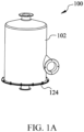
- FIG. 1A is a perspective view of a gas-liquid separator 100 according to an embodiment of this application.
- FIG. 1B is a partial cross-sectional view of the gas-liquid separator 100 shown in FIG. 1A .
- the gas-liquid separator 100 includes a housing assembly 102, an inner sleeve 106, and an additional gas-liquid separation apparatus 108.
- the housing assembly 102 defines a housing accommodation cavity 142 for accommodating the inner sleeve 106 and the additional gas-liquid separation apparatus 108.
- the gas-liquid separator 100 further includes an annular channel 110 between the housing assembly 102 and the inner sleeve 106.
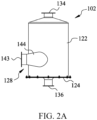
- FIG. 2A to FIG. 2D are respectively a side view, a top view, an axial cross-sectional view, and an exploded view of the housing assembly 102 shown in FIG. 1A .
- the housing assembly 102 includes an outer housing 122, an inlet pipe 128, a lower cover 124, and a housing bushing 104.
- the outer housing 122 is generally a cylindrical body extending in a height direction, which has a central axis X. a lower portion of the outer housing 122 has an opening, and a flange 123 is formed on the edge of the opening for connecting with the lower cover 124.
- An upper portion of the outer housing 122 is gradually contracted, and a gas outlet 134 is formed at a top portion for discharging gas.
- a side portion of the outer housing 122 is provided with a housing inlet (not shown) for communicating with the inlet pipe 128.
- the outer housing 122 has an inner side wall.
- a first limiting portion 231 and a second limiting portion 232 are arranged on the inner side wall of the outer housing 122.
- the first limiting portion 231 and the second limiting portion 232 respectively protrude radially inward from the inner side wall of the outer housing 122, and are respectively configured to limit an upper portion of the additional gas-liquid separation apparatus 108 and an upper portion of the housing bushing 104.
- the additional gas-liquid separation apparatus 108 and the housing bushing 104 may sequentially enter the outer housing 122 through the opening at the lower portion of the outer housing 122, and are assembled in place.
- the housing bushing 104 is substantially barrel-shaped, and an outer wall of the housing bushing 104 is arranged in close contact with the inner side wall of the outer housing 122. Therefore, at least a portion of the housing accommodation cavity 142 is defined by the inner side wall 244 of the housing bushing 104.
- An inlet 132 is provided on the inner side wall 244. In an example, the inlet 132 has a size and a shape completely the same as those of the housing inlet, and the inlet 132 is aligned with the housing inlet to allow a fluid to pass through the inlet pipe 128 and then flow through the housing inlet and the inlet 132 into the housing accommodation cavity 142.
- the inlet 132 is arranged at a middle portion of the outer housing 122 in the height direction, to ensure that the lower portion of the inlet 132 has sufficient depth to accommodate separated liquid, and the upper portion of the inlet 132 has enough space to install the additional gas-liquid separation apparatus 108.
- a plurality of first ribs 222 are arranged on the inner side wall 244 of the housing bushing 104.
- each of the plurality of first ribs 222 is formed by extending substantially along a straight line.
- Cross-sectional shapes of the plurality of first ribs 222 may be triangles, circles, squares, and the like.
- Each of the plurality of first ribs 222 is arranged at an angle ⁇ with respect to the height direction (that is, the X-axis direction) of the housing bushing 104.
- Each first rib 222 includes a first rib windward end (or a head end) 252 and a first rib leeward end (or a tail end) 254.
- the first rib windward end 252 is located upstream of the first rib leeward end 254.
- the flow direction of the fluid flowing into the housing accommodation cavity 142 from the inlet 132 refers to a movement direction of the fluid along the annular shape after entering the annular channel 110 from the inlet 132.
- the flow direction of the fluid flowing into the housing accommodation cavity 142 from the inlet 132 is a counterclockwise direction in the annular channel 110 as shown in FIG. 2B .
- a height of the first rib windward end 252 is higher than a height of the first rib leeward end 254.
- the fluid can impact the first ribs 222, so that the liquid in the fluid hits the first ribs 222 and then adheres to the first ribs 222, to separate the liquid from the gas.
- the angle ⁇ between each of the plurality of first ribs 222 and the height direction is greater than 0° and less than 45°.
- the lengths of the first ribs 222 are longer in the height direction, to improve the possibility that the fluid hits the first ribs 222, and the fluid (for example, separated gas) near the first ribs 222 can be induced to move obliquely downward, to accelerate the downward fall of the liquid collected on the first ribs 222 by using the movement of the fluid, thereby improving the separation rate of the liquid and the gas.
- the fluid for example, separated gas
- the plurality of first ribs 222 are further arranged into a plurality of groups of first ribs.
- Each group of first ribs is arranged along the height direction of the housing bushing 104, and a plurality of groups of first ribs are arranged along a circumferential direction of the inner side wall 244 and are spaced apart from each other, so that the liquid adhering to the first ribs 222 can slide down to the bottom portion of the housing accommodation cavity 142 along the inner side wall 244 (that is, at the intervals of the plurality of groups of first ribs) of the housing bushing 104.
- a first rib leeward end 254 of a first rib 222 at a higher height is located downstream of a first rib leeward end 254 of a first rib 222 at a lower height.
- a plurality of first rib leeward ends 254 form a straight line, which forms an angle ⁇ with the height direction.
- the value range of the angle ⁇ is greater than 0° and less than 30°.
- a bottom portion of the housing bushing 104 is further provided with a plurality of grooves 152 for matching protruding portions 153 on the lower cover 124, to prevent the housing bushing 104 from rotating with respect to the outer housing 122 due to the impact of the fluid entering the housing assembly 102.
- the lower cover 124 is substantially disc-shaped, and a liquid outlet 136 is provided on the lower cover 124 for discharging the liquid separated from the gas.
- the lower cover 124 is connected to the lower portion of the outer housing 122 through a connecting member 151.
- the connecting member 151 is a nut and a screw.
- the connecting member 151 may be alternatively other known connecting manners.
- the upper portion of the lower cover 124 is provided with the plurality of protruding portions 153, and the plurality of protruding portions 153 can be snapped into the plurality of grooves 152 at the bottom portion of the housing bushing 104, to prevent the housing bushing 104 from rotating in the outer housing 122.
- the upper portion of the lower cover 124 is further provided with a plurality of protruding rods 154.
- the plurality of protruding rods 154 can cooperate with a plurality of connecting portions 312 (referring to FIG. 3 ) in the inner sleeve body 302 to be connected to the inner sleeve body 302.
- the housing assembly 102 further includes an inlet pipe 128.
- the inlet pipe 128 has a central axis Y.
- the central axis Y is perpendicular to a radial direction of the outer housing 122, and has a vertical point close to the edge of the outer housing 122, so that the fluid entering the housing accommodation cavity 142 from the inlet pipe 128 can flow against the inner side wall 244 of the housing accommodation cavity 142 as much as possible.
- the inlet pipe 128 includes a first inlet pipe section 143 and a second inlet pipe section 144, where the first inlet pipe section 143 is communicated with the housing inlet through the second inlet pipe section 144.
- the first inlet pipe section 143 is a circular pipe section.
- the second inlet pipe section 144 is an elliptical pipe section.
- the second inlet pipe section 144 is arranged such that a size of the elliptical pipe section in the height direction (that is, along the central axis X direction) of the outer housing 122 is larger than a size of the elliptical pipe section in the horizontal direction, so that when the fluid enters the housing accommodation cavity 142 from the inlet pipe 128, the fluid can flow and spread in the height direction. In this way, more fluid can flow against the inner side wall 244 of the housing accommodation cavity 142, improving the liquid collection efficiency.
- first inlet pipe section 143 is a circular pipe section and the second inlet pipe section 144 is an elliptical pipe section in this application
- the size of the second inlet pipe section 144 is larger than that of the first inlet pipe section 143 in the height direction of the outer housing 122. This is because when the size of the second inlet pipe section 144 is larger than that of the first inlet pipe section 143, a jet effect can be generated on the fluid in the height direction.
- housing assembly 102 includes the outer housing 122 and the housing bushing 104 in this embodiment, and the housing bushing 104 abuts on the inner side wall of the outer housing 122, in some other embodiments, the outer housing 122 and the housing bushing 104 may be alternatively formed integrally.
- FIG. 3 is a side view of the inner sleeve 106 shown in FIG. 1A .
- the inner sleeve 106 includes an inner sleeve body 302 and an annular baffle 332.
- the inner sleeve body 302 is substantially cylindrical and defines an inner sleeve accommodation cavity 304.
- a lower portion of the inner sleeve body 302 is configured for connecting with the lower cover 124, to enable the inner sleeve accommodation cavity 304 to be communicated with the liquid outlet 136.
- the lower portion of the inner sleeve body 302 is provided with the plurality of connecting portions 312, in which holes are provided to accommodate the plurality of protruding rods 154 on the lower cover 124, so that the inner sleeve body 302 is connected to the lower cover 124.
- An upper portion of the inner sleeve body 302 is provided with the annular baffle 332.
- the annular baffle 332 is formed by extending horizontally outward from an upper edge of the inner sleeve body 302.
- annular baffle 332 When the inner sleeve 106 is assembled in the housing assembly 102, an outer edge of the annular baffle 332 abuts the inner side wall 244 of the housing bushing 104, and the outer side wall of the inner sleeve body 302 is spaced apart from the inner side wall of the outer housing 122, so that the housing bushing 104, the inner sleeve 106, and the lower cover 124 collectively define the annular channel 110.
- the lower portion of the inner sleeve body 302 is further provided with a plurality of communication ports 306, to enable the annular channel 110 to be communicated with the inner sleeve accommodation cavity 304 through the communication ports 306.
- the inner sleeve 106 further includes a plurality of second ribs 322.
- the plurality of second ribs 322 are arranged on the outer side wall 344 of the inner sleeve body 302.
- each of the plurality of second ribs 322 is formed by extending substantially along a straight line.
- Cross-sectional shapes of the plurality of second ribs 322 may be triangles, circles, squares, and the like.
- Each of the plurality of second ribs 322 is arranged at an angle ⁇ with respect to the height direction of the housing assembly 102.
- Each second rib 322 includes a second rib windward end (or a head end) 352 and a second rib leeward end (or a tail end) 354.
- the second rib windward end 352 is located upstream of the second rib leeward end 354.
- a height of the second rib windward end 352 is higher than a height of the second rib leeward end 354.
- the fluid can impact the second ribs 322, so that the liquid in the fluid hits the second ribs 322 and then adheres to the second ribs 322, to separate the liquid from the gas.
- the angle ⁇ between each of the plurality of second ribs 322 and the height direction is greater than 0° and less than 45°.
- the lengths of the second ribs 322 are longer in the height direction, to improve the possibility that the fluid hits the second ribs 322, and the fluid (for example, separated gas) near the second ribs 322 can be induced to move obliquely downward, to accelerate the downward fall of the liquid collected on the second ribs 322 by using the movement of the fluid, thereby improving the separation rate of the liquid and the gas.
- the fluid for example, separated gas
- the plurality of second ribs 322 are further arranged into a plurality of groups of second ribs.
- Each group of second ribs is arranged along the height direction of the housing assembly 102, and a plurality of groups of second ribs are arranged along a circumferential direction of the inner sleeve body 302 and are spaced apart from each other, so that the liquid adhering to the second ribs can slide down to the bottom portion of the annular channel 110 along the outer side wall 344 (that is, at the intervals of the plurality of groups of second ribs) of the inner sleeve body 302.
- a second rib leeward end 354 of a second rib 322 at a higher height is located downstream of a second rib windward end 352 of a second rib 322 at a lower height.
- a plurality of second rib leeward ends 354 form a straight line, which forms an angle ⁇ with the height direction.
- the value range of the angle ⁇ is greater than 0° and less than 30°.
- FIG. 4A and FIG. 4B are respectively an exploded view and an enlarged cross-sectional view of the additional gas-liquid separation apparatus 108.
- the additional gas-liquid separation apparatus 108 includes a first plate 401 and a second plate 402.
- the first plate 401 and the second plate 402 have the same structure. Therefore, the specific structure of the first plate 401 is described as an example below:
- the first plate 401 is substantially a circular disk that can be matched with the inner side wall of the outer housing 122, and includes a plurality of bent channels running vertically through the first plate 401.
- Each of the plurality of bent channels includes a first vertical channel 431 and a first inclined channel 432.
- the first vertical channels 431 are substantially vertically distributed with respect to the horizontal direction, so that the fluid can more easily enter the additional gas-liquid separation apparatus 108.
- the first inclined channels 432 are distributed at 45° with respect to the horizontal direction, so that the flow direction of the fluid entering the bent channels is changed.
- the first plate 401 further includes a pair of mounting holes 441 and a pair of protruding portions 442.
- the pair of mounting holes 441 are vertically arranged through the first plate 401 and are arranged at two opposite edges on the same diameter of the first plate 401.
- the pair of protruding portions 442 are formed by extending downward from the lower surface of the first plate 401 and are also arranged at two opposite edges on the same diameter of the first plate 401.
- the straight line connecting the pair of mounting holes 441 is substantially perpendicular to the straight line connecting the pair of protruding portions 442, thereby enhancing the stability.
- the second plate 402 includes a plurality of bent channels. Each of the plurality of bent channels includes a second vertical channel 451 and a second inclined channel 452. The second plate 402 further includes a pair of mounting holes 461 and a pair of protruding portions 462.
- the first plate 401 and the second plate 402 can form the additional gas-liquid separation apparatus 108 by simple assembly. Specifically, the first plate 401 and the second plate 402 are stacked, the pair of protruding portions 442 in the first plate 401 are inserted into the pair of mounting holes 461 in the second plate 402, and the pair of protruding portions 462 in the second plate 402 are inserted into the pair of mounting holes 441 in the first plate 401. When the first plate 401 and the second plate 402 are stacked and assembled in place, the bent channels in the first plate 401 and the bent channels in the second plate 402 are communicated with each other.
- the first inclined channels 432 in the first plate 401 are communicated with the second inclined channels 452 in the second plate 402 to form the bent channels.
- the value range of the angle formed by the first inclined channel 432 and the second inclined channel 452 is greater than or equal to 45° and less than or equal to 90°.
- the thickness of the first plate 401 and the second plate 402 is about 10 to 30 mm, and the width of the bent channels in the first plate 401 and the bent channels in the second plate 402 is about 4 to 10 mm.
- the conventional additional gas-liquid separation apparatus includes a base plate and a plurality of partition plates.
- the plurality of partition plates are spaced apart from each other and fixed on the base plate by connecting members, to form a plurality of bent channels for receiving the mixed fluid.
- the mounting process of such a conventional additional gas-liquid separation apparatus is very complex, and each of the plurality of partition plates needs to be fixed to the base plate by a connecting member, which increases the processing time and the costs of components.
- the additional gas-liquid separation apparatus 108 in this application has the advantages of easy production and simple assembly.
- the first plate 401 and the second plate 402 in the additional gas-liquid separation apparatus 108 in this application have the same structure, and both include inclined channels and vertical channels.
- the vertical channels facilitate the entry and exit of the mixed fluid into and out of the additional gas-liquid separation apparatus 108, and the inclined channels and the vertical channels are bent to change the movement direction of the mixed fluid.
- the configuration of the inclined channels and the vertical channels allows the additional gas-liquid separation apparatus 108 of this application to be made of plastic and produced by molding. The molding production manner can greatly improve the manufacturing efficiency.
- the first plate 401 and the second plate 402 can be mounted through the pair of mounting holes 461 and the pair of protruding portions provided thereon without requiring additional connecting members or processing tools.
- other materials with good hydrophobicity for example, Teflon
- Teflon can be further coated on the additional gas-liquid separation apparatus 108 made of plastic, thereby increasing the gas-liquid separation rate of the additional gas-liquid separation apparatus 108.
- the additional gas-liquid separation apparatus 108 is mounted in the outer housing 122.
- the upper portion of the additional gas-liquid separation apparatus 108 abuts the first limiting portion 231 (referring to FIG. 2C ), and the lower portion of the additional gas-liquid separation apparatus 108 abuts the housing bushing 104, so that the additional gas-liquid separation apparatus is assembled in the outer housing 122. Therefore, the housing accommodation cavity 142 is divided into an upper accommodation cavity and a lower accommodation cavity by the additional gas-liquid separation apparatus 108.
- Both the housing bushing 104 and the inner sleeve 106 are arranged in the lower accommodation cavity. The fluid in the lower accommodation cavity needs to pass through the bent channels in the additional gas-liquid separation apparatus 108 to enter the upper accommodation cavity.
- a flow path of the gas and liquid mixed fluid (referred to as "mixed fluid” below) after entering the gas-liquid separator 100 from the inlet pipe 128 is described below with reference to FIG. 1B .
- the mixed fluid flows into the housing inlet from the first inlet pipe section 143 and the second inlet pipe section 144.
- the mixed fluid flows in the second inlet pipe section 144, since the size of the second inlet pipe section 144 in the height direction increases, the mixed fluid generates a jet in the height direction.
- a contact area of the mixed fluid where the jet occurs and the inner side wall 244 of the housing bushing 104 increases, thereby increasing the probability of hitting the inner side wall 244 and the plurality of first ribs 222 arranged on the inner side wall 244 by the mixed fluid.
- the liquid in the mixed fluid entering the annular channel 110 hits the inner side wall 244 of the housing bushing 104 and the first ribs 222 arranged on the inner side wall 244 due to a greater centrifugal force thereof than the gas.
- a liquid film is formed on the inner side wall 244 of the housing bushing 104 and the plurality of first ribs 222 and falls due to gravity.
- the flow direction of the mixed fluid in the annular channel 110 continuously changes along the annular channel 110, and the mixed fluid hits the outer side wall 344 of the inner sleeve 106 and the plurality of second ribs 322 arranged on the outer side wall 344. Therefore, a portion of the liquid in the mixed fluid also forms a liquid film on the outer side wall 344, which falls due to gravity.
- the liquid separated from the mixed fluid is deposited at the bottom portion of the annular channel 110 and is deposited at the bottom portion of the gas-liquid separator 100 through the plurality of communication ports 306.
- a valve may be arranged on the liquid outlet 136, so that the liquid outlet 136 is disconnected from the external pipeline, and the liquid separated from the mixed fluid is deposited at the bottom portion. The liquid deposited at the bottom portion can create a liquid seal, so that the gas cannot flow out of the gas-liquid separator 100 directly through the liquid outlet 136.
- the remaining mixed fluid in the annular channel 110 cannot leave the annular channel 110 from above, but can only flow into the inner sleeve accommodation cavity 304 through the plurality of communication ports 306 and then flow upward.
- the mixed fluid carrying the smaller volume of liquid flows from the lower accommodation cavity to the upper accommodation cavity, the mixed fluid needs to pass through the bent channels in the first plate 401 and the second plate 402. More specifically, the mixed fluid passes through the second vertical channels 451 and the second inclined channels 452 in the second plate 402 and the first inclined channels 432 and the first vertical channels 431 in the first plate 401 in sequence. In the bent channels, the mixed fluid needs to change the flow direction for three times to pass through the bent channels.
- the liquid is impacted in the bent channels under the action of the inertial force, and flows to the bottom portion of the gas-liquid separator 100 under the action of gravity.
- the gas can flow upward through the bent channels, enter the upper accommodation cavity after passing through the additional gas-liquid separation apparatus 108, and then flow out of the gas-liquid separator 100 through the gas outlet 134.
- the mixed fluid entering the gas-liquid separator 100 from the inlet pipe 128 moves in the lower accommodation cavity.
- the mixed fluid needs to undergo changes in the flow direction at least twice.
- One of the changes is the change in the flow direction when the mixed fluid hits the annular channel 110, and the other is the change in the flow direction when the mixed fluid flows into the inner sleeve accommodation cavity 304 from the annular channel 110 through the plurality of communication ports 306 (the flow direction is changed from flowing downward to flowing upward).
- the changes in the flow direction enable most of the liquid with larger volume to separate from the mixed fluid.
- liquid with a particle size greater than 100 um in the mixed fluid can be collected.
- the mixed fluid then passes through the additional gas-liquid separation apparatus 108, and is separated again in the additional gas-liquid separation apparatus 108.
- the additional gas-liquid separation apparatus 108 can separate droplets with a particle size larger than 10 um. So far, the gas-liquid separator 100 of this application can separate liquid with a large particle size and a small particle size from the fluid, thereby achieving a higher separation rate.
- the inner sleeve 106 includes the annular baffle 332 to seal the upper end of the annular channel 110 to force the mixed fluid to flow into the inner sleeve accommodation cavity 304 through the plurality of communication ports 306 below, in another example, the inner sleeve 106 may alternatively not include the annular baffle 332. In other words, after entering the annular channel 110, the mixed gas can flow toward the additional gas-liquid separation apparatus 108 from the upper end of the annular channel 110.
- the gas-liquid separator 100 of this application mainly realizes the gas-liquid separation of the mixed fluid by using the annular channel 110 and the additional gas-liquid separation apparatus 108.
- the first ribs and the second ribs are respectively arranged on the inner side wall and the outer side wall of the annular channel 110, thereby increasing the separation efficiency of the liquid.
- the gas-liquid separator 100 according to this application has a compact structure, a small overall volume, and high separation efficiency.
Landscapes
- Chemical & Material Sciences (AREA)
- Chemical Kinetics & Catalysis (AREA)
- Separating Particles In Gases By Inertia (AREA)
Applications Claiming Priority (2)
| Application Number | Priority Date | Filing Date | Title |
|---|---|---|---|
| CN202010494328.9A CN113750653B (zh) | 2020-06-03 | 2020-06-03 | 气液分离器 |
| PCT/CN2021/097159 WO2021244465A1 (zh) | 2020-06-03 | 2021-05-31 | 气液分离器 |
Publications (3)
| Publication Number | Publication Date |
|---|---|
| EP4163003A1 true EP4163003A1 (de) | 2023-04-12 |
| EP4163003A4 EP4163003A4 (de) | 2024-04-17 |
| EP4163003B1 EP4163003B1 (de) | 2025-10-08 |
Family
ID=78783115
Family Applications (1)
| Application Number | Title | Priority Date | Filing Date |
|---|---|---|---|
| EP21818284.8A Active EP4163003B1 (de) | 2020-06-03 | 2021-05-31 | Gas-flüssigkeitsabscheider |
Country Status (4)
| Country | Link |
|---|---|
| US (1) | US12508526B2 (de) |
| EP (1) | EP4163003B1 (de) |
| CN (1) | CN113750653B (de) |
| WO (1) | WO2021244465A1 (de) |
Family Cites Families (56)
| Publication number | Priority date | Publication date | Assignee | Title |
|---|---|---|---|---|
| US432491A (en) * | 1890-07-15 | Dust-collector | ||
| US468935A (en) * | 1892-02-16 | Orville m | ||
| US814837A (en) * | 1904-11-08 | 1906-03-18 | Ephraim H Fenton | Pneumatic dust removing and collecting apparatus. |
| US1055792A (en) * | 1912-05-24 | 1913-03-11 | Albert F Plock | Dry gas-cleaner. |
| DE324260C (de) * | 1918-10-18 | 1920-08-23 | Emil Schierholz | Vorrichtung zum Auswaschen bzw. Ausscheiden mechanischer Beimengungen aus Gasen, Daempfen und Fluessigkeiten |
| DE414140C (de) * | 1923-11-01 | 1925-05-25 | Serge Bounakoff | Cyklonfluessigkeitsabscheider fuer Gas-, Dampf- oder Luftstroeme |
| US2010128A (en) * | 1931-09-17 | 1935-08-06 | Gerald D Arnold | Centrifugal separator |
| US2222930A (en) * | 1939-04-14 | 1940-11-26 | Gerald D Arnold | Centrifugal separator |
| US2351864A (en) * | 1940-06-27 | 1944-06-20 | Jr Garrett B Linderman | Dust collector |
| NL52376C (de) * | 1940-09-09 | |||
| US2542635A (en) | 1948-01-27 | 1951-02-20 | Apex Electrical Mfg Co | Centrifugal dust separator |
| DE1239055B (de) * | 1963-11-27 | 1967-04-20 | August Hornkohl K G | Abscheider zum Entfernen unerwuenschter fluessiger und/oder fester Fremdbestandteile aus stroemenden Druckgasen |
| US3399770A (en) * | 1966-01-19 | 1968-09-03 | Beloit Corp | Method for centrifugal separation of particles from a mixture |
| US3513642A (en) * | 1968-07-25 | 1970-05-26 | Milan S Cornett | Centrifugal dust separator |
| US3577711A (en) * | 1969-06-02 | 1971-05-04 | Us Agriculture | Apparatus for removing entrained particles from gases |
| US3951620A (en) * | 1974-09-19 | 1976-04-20 | Shell Oil Company | Separation apparatus and process |
| US3961922A (en) * | 1975-01-02 | 1976-06-08 | Dallas Research Enterprises | Vane separator |
| US4229194A (en) * | 1978-11-20 | 1980-10-21 | Atlantic Richfield Company | Vapor-solids separating device |
| US4251242A (en) * | 1979-02-12 | 1981-02-17 | Ngk Insulators, Ltd. | Mist eliminator |
| US4514202A (en) | 1983-04-25 | 1985-04-30 | The Marley Cooling Tower Company | Air stream entrained water eliminator for cross flow cooling tower |
| US4600410A (en) * | 1984-12-19 | 1986-07-15 | Atlantic Richfield Company | Process and apparatus for separating particulate matter from a gaseous medium |
| US4784674A (en) * | 1987-08-05 | 1988-11-15 | Flakt, Inc. | Mist eliminator module and a method for self-cleaning of the same |
| US4834887A (en) * | 1988-03-10 | 1989-05-30 | Broughton Amos W | In-line coaxial centrifugal separator with helical vane |
| US5085826A (en) * | 1990-12-20 | 1992-02-04 | General Electric Company | Steam dryer |
| US5137554A (en) * | 1991-09-09 | 1992-08-11 | Fasco Industries, Inc. | Cyclonic vacuum cleaner cone |
| US5320651A (en) * | 1993-06-28 | 1994-06-14 | Munters Corporation | Cross-flow film fill media with intergral drift eliminator |
| US6264712B1 (en) * | 1999-04-07 | 2001-07-24 | American Farm Implement & Specialty, Inc. | Low intake restriction air precleaner |
| CA2583076C (en) * | 2001-06-13 | 2011-01-18 | National Tank Company | A system for separating an entrained liquid component from a gas stream |
| US6837912B1 (en) * | 2002-04-22 | 2005-01-04 | Fisher-Klosterman, Inc. | Cyclone separator with surface vanes |
| US6770121B1 (en) * | 2002-09-12 | 2004-08-03 | Harbison-Fischer, Inc. | Separator with regions of differing surface tensions |
| WO2007012823A2 (en) * | 2005-07-26 | 2007-02-01 | Parker Hannifin Limited | Separator assembly |
| US8034143B2 (en) * | 2008-03-18 | 2011-10-11 | Uti Limited Partnership | Cyclone |
| US8245532B2 (en) * | 2008-05-15 | 2012-08-21 | Concepts Eti, Inc. | Semi-closed air-cycle refrigeration system and a positive-pressure snow removal cyclone separator therefor |
| AU2009202180B2 (en) * | 2008-06-05 | 2014-10-23 | Bissell Inc. | Cyclonic vacuum cleaner with improved collection chamber |
| US7674304B2 (en) * | 2008-06-26 | 2010-03-09 | Brentwood Industries, Inc. | Drift eliminator with formed beveled tip |
| MY158692A (en) * | 2009-09-04 | 2016-10-31 | Sulzer Chemtech Ag | Drained coalescer |
| US8336136B1 (en) * | 2010-11-09 | 2012-12-25 | Susanne Debora Lantos | Panel assembly for a partial drop-side crib |
| US8273158B2 (en) * | 2010-11-29 | 2012-09-25 | General Electric Company | Mist eliminator, moisture removal system, and method of removing water particles from inlet air |
| US9761416B2 (en) * | 2013-03-15 | 2017-09-12 | Applied Materials, Inc. | Apparatus and methods for reducing particles in semiconductor process chambers |
| CN203447899U (zh) * | 2013-08-28 | 2014-02-26 | 个旧市云新有色电解有限公司 | 一种螺旋导流汽水分离器 |
| CN203648273U (zh) * | 2013-11-07 | 2014-06-18 | 中石化洛阳工程有限公司 | 一种高效除雾器 |
| CN104548840A (zh) * | 2014-12-18 | 2015-04-29 | 广西大学 | 压缩液化制取高纯度页岩气用气液分离器 |
| CN104623987B (zh) * | 2015-02-03 | 2016-08-24 | 东南大学 | 一种用于提高小粒径雾滴除雾效率的除雾器 |
| DE102017006471B4 (de) * | 2016-08-08 | 2021-11-18 | Mann+Hummel Gmbh | Filter und Zyklonfiltersystem |
| WO2018027314A1 (en) * | 2016-08-09 | 2018-02-15 | Rodney Allan Bratton | In-line swirl vortex separator |
| CN206315572U (zh) * | 2016-12-19 | 2017-07-11 | 四川茵地乐科技有限公司 | 用于制胶废气的气液分离器 |
| CN206285624U (zh) * | 2016-12-19 | 2017-06-30 | 临安派祺空气净化科技有限公司 | 一种汽水旋风分离器 |
| CN206897013U (zh) * | 2017-05-19 | 2018-01-19 | 德哈哈压缩机江苏有限公司 | 螺旋气液分离器及包含其的空气压缩机 |
| CN108993065A (zh) * | 2017-06-06 | 2018-12-14 | 安瑞科(蚌埠)压缩机有限公司 | 气液固分离器 |
| CN207237488U (zh) * | 2017-07-06 | 2018-04-17 | 南通锐深环保科技有限公司 | 一种改进型除雾器的液滴分液器 |
| CN208436527U (zh) * | 2018-06-06 | 2019-01-29 | 北京国能中电节能环保技术股份有限公司 | 一种除沫装置 |
| CN110870998A (zh) * | 2018-09-02 | 2020-03-10 | 惠州道尚智能科技有限公司 | 一种气液分离储液罐 |
| CN109442588B (zh) * | 2018-11-30 | 2024-01-23 | 广东美的制冷设备有限公司 | 出风装置和空气处理装置 |
| CN209679678U (zh) * | 2018-12-26 | 2019-11-26 | 汉格斯特滤清系统(昆山)有限公司 | 一种旋风式分离器 |
| CN209662812U (zh) * | 2018-12-29 | 2019-11-22 | 天津天元伟业化工技术有限公司 | 一种除雾效果好的折流板除雾器 |
| CN209558558U (zh) * | 2019-01-31 | 2019-10-29 | 广东美的制冷设备有限公司 | 空气处理装置 |
-
2020
- 2020-06-03 CN CN202010494328.9A patent/CN113750653B/zh active Active
-
2021
- 2021-05-31 EP EP21818284.8A patent/EP4163003B1/de active Active
- 2021-05-31 WO PCT/CN2021/097159 patent/WO2021244465A1/zh not_active Ceased
- 2021-05-31 US US18/007,937 patent/US12508526B2/en active Active
Also Published As
| Publication number | Publication date |
|---|---|
| US12508526B2 (en) | 2025-12-30 |
| US20230249111A1 (en) | 2023-08-10 |
| CN113750653A (zh) | 2021-12-07 |
| WO2021244465A1 (zh) | 2021-12-09 |
| CN113750653B (zh) | 2022-08-19 |
| EP4163003A4 (de) | 2024-04-17 |
| EP4163003B1 (de) | 2025-10-08 |
Similar Documents
| Publication | Publication Date | Title |
|---|---|---|
| US7279020B2 (en) | Axial demisting cyclone | |
| US10328379B2 (en) | Filtration liquid tank for dedusting device, and dedusting device with the same | |
| US8974568B2 (en) | Inertial separator for gas liquid separation | |
| EP3653306A1 (de) | Zerstäuberscheibe, zerstäubungsvorrichtung damit und drohne | |
| US20190091703A1 (en) | Dust collector and cleaner having the same | |
| CN213790418U (zh) | 气液分离器 | |
| EP3984428A1 (de) | Zyklonabscheider und reinigungsgerät | |
| JP2006518274A (ja) | 分離トレイ | |
| CN117404742A (zh) | 空气净化器 | |
| CN109751798A (zh) | 气液分离器 | |
| US12508526B2 (en) | Gas-liquid separator | |
| US20190091702A1 (en) | Dust collector and cleaner having the same | |
| WO2022047728A1 (zh) | 一种旋风分离装置及清洁设备 | |
| US20240278161A1 (en) | Chimney for impactor nozzles and integrated assembly | |
| CN218516287U (zh) | 一种组合式高效分离内件及气液分离器 | |
| CN116114091B (zh) | 气液分离器和包括该气液分离器的燃料电池系统 | |
| CN212774460U (zh) | 旋风式分离器 | |
| EP2452734A1 (de) | Filterkartusche und Schmutztrennungsvorrichtung für Wärmeflüssigkeit | |
| CN204830609U (zh) | 气液分离装置及具有其的空调器 | |
| CN114234497A (zh) | 一种储液器和压缩机组件 | |
| CN116171201A (zh) | 涡流导流器和旋风分离器 | |
| CN216909797U (zh) | 一种自冷型气液分离器 | |
| CN213309469U (zh) | 一种旋风分离装置 | |
| CN104964493A (zh) | 气液分离装置及具有其的空调器 | |
| CN223089380U (zh) | 分离组件、油壶和发动机 |
Legal Events
| Date | Code | Title | Description |
|---|---|---|---|
| STAA | Information on the status of an ep patent application or granted ep patent |
Free format text: STATUS: THE INTERNATIONAL PUBLICATION HAS BEEN MADE |
|
| PUAI | Public reference made under article 153(3) epc to a published international application that has entered the european phase |
Free format text: ORIGINAL CODE: 0009012 |
|
| STAA | Information on the status of an ep patent application or granted ep patent |
Free format text: STATUS: REQUEST FOR EXAMINATION WAS MADE |
|
| 17P | Request for examination filed |
Effective date: 20230103 |
|
| AK | Designated contracting states |
Kind code of ref document: A1 Designated state(s): AL AT BE BG CH CY CZ DE DK EE ES FI FR GB GR HR HU IE IS IT LI LT LU LV MC MK MT NL NO PL PT RO RS SE SI SK SM TR |
|
| DAV | Request for validation of the european patent (deleted) | ||
| DAX | Request for extension of the european patent (deleted) | ||
| A4 | Supplementary search report drawn up and despatched |
Effective date: 20240314 |
|
| RIC1 | Information provided on ipc code assigned before grant |
Ipc: B04C 5/103 20060101ALI20240308BHEP Ipc: B01D 45/06 20060101ALI20240308BHEP Ipc: B01D 45/16 20060101AFI20240308BHEP |
|
| STAA | Information on the status of an ep patent application or granted ep patent |
Free format text: STATUS: EXAMINATION IS IN PROGRESS |
|
| 17Q | First examination report despatched |
Effective date: 20241212 |
|
| GRAP | Despatch of communication of intention to grant a patent |
Free format text: ORIGINAL CODE: EPIDOSNIGR1 |
|
| STAA | Information on the status of an ep patent application or granted ep patent |
Free format text: STATUS: GRANT OF PATENT IS INTENDED |
|
| INTG | Intention to grant announced |
Effective date: 20250514 |
|
| GRAS | Grant fee paid |
Free format text: ORIGINAL CODE: EPIDOSNIGR3 |
|
| GRAA | (expected) grant |
Free format text: ORIGINAL CODE: 0009210 |
|
| STAA | Information on the status of an ep patent application or granted ep patent |
Free format text: STATUS: THE PATENT HAS BEEN GRANTED |
|
| AK | Designated contracting states |
Kind code of ref document: B1 Designated state(s): AL AT BE BG CH CY CZ DE DK EE ES FI FR GB GR HR HU IE IS IT LI LT LU LV MC MK MT NL NO PL PT RO RS SE SI SK SM TR |
|
| REG | Reference to a national code |
Ref country code: GB Ref legal event code: FG4D Ref country code: CH Ref legal event code: F10 Free format text: ST27 STATUS EVENT CODE: U-0-0-F10-F00 (AS PROVIDED BY THE NATIONAL OFFICE) Effective date: 20251008 |
|
| REG | Reference to a national code |
Ref country code: DE Ref legal event code: R096 Ref document number: 602021040151 Country of ref document: DE |
|
| REG | Reference to a national code |
Ref country code: IE Ref legal event code: FG4D |
|
| REG | Reference to a national code |
Ref country code: NL Ref legal event code: MP Effective date: 20251008 |
|
| REG | Reference to a national code |
Ref country code: AT Ref legal event code: MK05 Ref document number: 1844399 Country of ref document: AT Kind code of ref document: T Effective date: 20251008 |
|
| PG25 | Lapsed in a contracting state [announced via postgrant information from national office to epo] |
Ref country code: NL Free format text: LAPSE BECAUSE OF FAILURE TO SUBMIT A TRANSLATION OF THE DESCRIPTION OR TO PAY THE FEE WITHIN THE PRESCRIBED TIME-LIMIT Effective date: 20251008 |
|
| REG | Reference to a national code |
Ref country code: CH Ref legal event code: W10 Free format text: ST27 STATUS EVENT CODE: U-0-0-W10-W00 (AS PROVIDED BY THE NATIONAL OFFICE) Effective date: 20260325 |