EP4162884A1 - Freisetzungsvorrichtung, system und verfahren sowie therapeutische vorrichtung - Google Patents
Freisetzungsvorrichtung, system und verfahren sowie therapeutische vorrichtung Download PDFInfo
- Publication number
- EP4162884A1 EP4162884A1 EP21818783.9A EP21818783A EP4162884A1 EP 4162884 A1 EP4162884 A1 EP 4162884A1 EP 21818783 A EP21818783 A EP 21818783A EP 4162884 A1 EP4162884 A1 EP 4162884A1
- Authority
- EP
- European Patent Office
- Prior art keywords
- release
- power consumption
- predetermined
- time duration
- predetermined timing
- Prior art date
- Legal status (The legal status is an assumption and is not a legal conclusion. Google has not performed a legal analysis and makes no representation as to the accuracy of the status listed.)
- Withdrawn
Links
- 238000000034 method Methods 0.000 title claims abstract description 286
- 230000001225 therapeutic effect Effects 0.000 title claims abstract description 13
- 230000008569 process Effects 0.000 claims abstract description 242
- 239000004020 conductor Substances 0.000 claims description 23
- 239000007943 implant Substances 0.000 claims description 21
- 238000004891 communication Methods 0.000 claims description 12
- 238000001514 detection method Methods 0.000 claims description 6
- 239000003792 electrolyte Substances 0.000 claims description 3
- 201000008450 Intracranial aneurysm Diseases 0.000 description 7
- 238000002560 therapeutic procedure Methods 0.000 description 4
- 206010002329 Aneurysm Diseases 0.000 description 3
- 238000010586 diagram Methods 0.000 description 3
- 238000012986 modification Methods 0.000 description 3
- 230000004048 modification Effects 0.000 description 3
- 210000001124 body fluid Anatomy 0.000 description 2
- 239000010839 body fluid Substances 0.000 description 2
- 230000010102 embolization Effects 0.000 description 2
- 238000009413 insulation Methods 0.000 description 2
- 206010020772 Hypertension Diseases 0.000 description 1
- 230000009286 beneficial effect Effects 0.000 description 1
- 230000008878 coupling Effects 0.000 description 1
- 238000010168 coupling process Methods 0.000 description 1
- 238000005859 coupling reaction Methods 0.000 description 1
- 230000003247 decreasing effect Effects 0.000 description 1
- 238000005516 engineering process Methods 0.000 description 1
- 208000014674 injury Diseases 0.000 description 1
- 230000003993 interaction Effects 0.000 description 1
- 230000008733 trauma Effects 0.000 description 1
- 208000019553 vascular disease Diseases 0.000 description 1
Images


Classifications
-
- A—HUMAN NECESSITIES
- A61—MEDICAL OR VETERINARY SCIENCE; HYGIENE
- A61B—DIAGNOSIS; SURGERY; IDENTIFICATION
- A61B17/00—Surgical instruments, devices or methods
- A61B17/12—Surgical instruments, devices or methods for ligaturing or otherwise compressing tubular parts of the body, e.g. blood vessels or umbilical cord
- A61B17/12022—Occluding by internal devices, e.g. balloons or releasable wires
- A61B17/12099—Occluding by internal devices, e.g. balloons or releasable wires characterised by the location of the occluder
- A61B17/12109—Occluding by internal devices, e.g. balloons or releasable wires characterised by the location of the occluder in a blood vessel
- A61B17/12113—Occluding by internal devices, e.g. balloons or releasable wires characterised by the location of the occluder in a blood vessel within an aneurysm
-
- A—HUMAN NECESSITIES
- A61—MEDICAL OR VETERINARY SCIENCE; HYGIENE
- A61B—DIAGNOSIS; SURGERY; IDENTIFICATION
- A61B17/00—Surgical instruments, devices or methods
- A61B17/12—Surgical instruments, devices or methods for ligaturing or otherwise compressing tubular parts of the body, e.g. blood vessels or umbilical cord
- A61B17/12022—Occluding by internal devices, e.g. balloons or releasable wires
- A61B17/12131—Occluding by internal devices, e.g. balloons or releasable wires characterised by the type of occluding device
- A61B17/1214—Coils or wires
-
- A—HUMAN NECESSITIES
- A61—MEDICAL OR VETERINARY SCIENCE; HYGIENE
- A61B—DIAGNOSIS; SURGERY; IDENTIFICATION
- A61B17/00—Surgical instruments, devices or methods
- A61B2017/00017—Electrical control of surgical instruments
-
- A—HUMAN NECESSITIES
- A61—MEDICAL OR VETERINARY SCIENCE; HYGIENE
- A61B—DIAGNOSIS; SURGERY; IDENTIFICATION
- A61B17/00—Surgical instruments, devices or methods
- A61B17/12—Surgical instruments, devices or methods for ligaturing or otherwise compressing tubular parts of the body, e.g. blood vessels or umbilical cord
- A61B17/12022—Occluding by internal devices, e.g. balloons or releasable wires
- A61B2017/1205—Introduction devices
- A61B2017/12054—Details concerning the detachment of the occluding device from the introduction device
- A61B2017/12063—Details concerning the detachment of the occluding device from the introduction device electrolytically detachable
-
- A—HUMAN NECESSITIES
- A61—MEDICAL OR VETERINARY SCIENCE; HYGIENE
- A61B—DIAGNOSIS; SURGERY; IDENTIFICATION
- A61B17/00—Surgical instruments, devices or methods
- A61B17/12—Surgical instruments, devices or methods for ligaturing or otherwise compressing tubular parts of the body, e.g. blood vessels or umbilical cord
- A61B17/12022—Occluding by internal devices, e.g. balloons or releasable wires
- A61B2017/1205—Introduction devices
- A61B2017/12054—Details concerning the detachment of the occluding device from the introduction device
- A61B2017/1209—Details concerning the detachment of the occluding device from the introduction device detachable by electrical current or potential, e.g. electroactive polymer
Definitions
- the present invention relates to the technical field of medical instruments and, in particular, to a release device, system and method, and a therapeutic apparatus.
- Intracranial aneurysm is a common vascular disease that threatens middle-aged and elderly people.
- the aneurysm ruptures in patients due to high blood pressure. If no timely and effective therapeutic is given, it will be life-threatening.
- the traditional therapeutic method for intracranial aneurysm is mainly to clip the aneurysm by surgical operation, but it has the disadvantages of large trauma and high patient mortality.
- a commonly used interventional therapeutic method for intracranial aneurysm is to use a coil for embolization.
- the coil is connected to a push rod.
- the doctor pushes the push rod to deliver the coil to the diseased site where the intracranial aneurysm is located, and pushes the coil into the lumen of the aneurysm.
- the coil needs to be separated from the push rod, which requires a release process to be performed.
- the release process is carried out in the patient's body, and the doctor cannot observe the progress of the release. As a result, it is difficult for the doctor to determine the relase state. Therefore, it is eager to develop a release device capable of determining whether the coil has been completely released.
- An object of the present invention is to provide a release device, a relase system, a release method, and a therapeutic device, so as to improve the success rate in the release of the medical implant and improve the patient's use experience.
- the present invention provides a release device, applied to a release system, the release device comprising a power supply assembly, a current detector, a first timer and a control unit; wherein,
- the release device further comprises a second timer that is in communication with the control unit, and configured to detect a release time duration; wherein the control unit is configured to calculate the power consumption according to the current of the release circuit and the release time duration.
- control unit pre-stores a first predetermined timing and a first power consumption threshold
- the release device comprises a first release mode and a second release mode
- control unit further pre-stores a first predetermined current value for the first release mode and a second predetermined current value for the second release mode, and the second predetermined current value is greater than the first predetermined current value
- control unit is further configured to acquire an initial power consumption that refers to a power consumption of the release circuit during a time period from a beginning of the release process to the first predetermined timing, and determine that the first release mode or the second release mode is to be excuted for the release process according to the initial power consumption and the first power consumption threshold.
- control unit when the initial power consumption is less than the first power consumption threshold, the control unit is configured to execute the first release mode; the control unit further pre-stores a second predetermined timing and a third predetermined timing both for the first release mode, and the third predetermined timing is after the second predetermined timing;
- control unit pre-stores a second power consumption threshold and a first predetermined time duration, wherein the power consumption of the release circuit in the time period from beginning of the release process to the third predetermined timing is a second power consumption;
- control unit when the initial power consumption is greater than or equal to the first power consumption threshold, the control unit is configured to perform the release process in the second release mode;
- control unit pre-stores a third power consumption threshold and a second predetermined time duration
- control unit further pre-stores a fifth predetermined timing and a fourth power consumption threshold, the fifth predetermined timing is after the fourth predetermined timing, and the fourth power consumption threshold is greater than the third power consumption threshold; when the second accumulated time duration is greater than or equal to the second predetermined time duration, the control unit is configured to determine whether the third power consumption is greater than or equal to the fourth power consumption threshold, if so, determine that the release process is successful, and if not, control the power supply assembly to continue supplying power to the release circuit until the fifth predetermined timing is reached, and determine that the release process is successful at the fifth predetermined timing.
- the release device further comprises a third release mode
- the control unit further pre-stores a reference range of power consumption; after the release process is suspended, the control device is further configured to determine whether the stored power consumption is within the reference range of power consumption, if yes, execute the third release mode, and if not, determine that the release process is terminated.
- control unit pre-stores a third predetermined current value, a sixth predetermined timing and a fifth power consumption threshold; in the third release mode, the control unit is configured to: acquire a fourth power consumption that refers to the power consumption of the release circuit in a time period from the beginning of the third release mode to the sixth predetermined timing; determine whether the fourth power consumption is greater than or equal to the fifth power consumption threshold; determine whether a comparison current is less than the third predetermined current value, the comparison current refers to the current of the release circuit at a timing for comparison, the timing for comparison refers to a timing when the power consumption of the release circuit in the third release mode is greater than the fifth power consumption threshold; determine whether the timing for comparison is before the sixth predetermined timing; determine whether the third accumulated time duration is greater than or equal to the third predetermined time duration, the third accumulated time duration is an accumulated time duration over which the current of the release circuit is less than the third predetermined current value in the time period from the beginning of the third release mode to the sixth predetermined timing, if the third accumulated current value
- control unit is further configured to determine that the release process is terminated when the fourth power consumption is less than the fifth power consumption threshold, or when the comparison current is greater than the third predetermined current value.
- the release device further comprises a display element that is in communication with the control unit, and configured to display a release state of the release system.
- the power supply assembly comprises a constant current source and a current driver, wherein the constant current source and the current driver are both connected to the control unit, and the constant current source is configured to supply power to the release circuit through the current driver.
- the present invention also provides a release system, comprising a push rod and the above release device, wherein the push rod is configured to connect with the power supply assembly of the release device, and the power supply assembly is configured to supply power to positive and negative electrodes of the push rod to form the release circuit.
- the power supply assembly has a positive electrode and a negative electrode
- the push rod comprises a first electrical conductor and a second electrical conductor, wherein the first electrical conductor is connected to the negative electrode of the power supply assembly, the second electrical conductor comprises a conductive area and a release area that are connected to each other, wherein the conductive area is connected to the positive electrode of the power supply assembly, and the release area is configured to connect with the first electrical conductor through an electrolyte, wherein the power supply assembly is configured to supply power to the push rod to break the release area.
- the present invention also provides a therapeutic device, comprising a medical implant and the above release system, the medical implant is configurd to connect with the release system, and can be release from the release system in a predetermined condition.
- the present invention also provides a release method, comprising steps of:
- the release process performed by the release system is determined to be successful when the power consumption reaches a predetermined power consumption threshold, and when the accumulated time duration reaches a predetermined time duration.
- the release method further comprises:
- the predetermined current value is set according to a detection result of the present power consumption of the release circuit
- the release method further comprises a first release mode and a second release mode; wherein the release method comprises:
- the release method further comprises a third release mode; when the release process is determined to be not successful in Step S2, the release method further comprises:
- Step S1 the first release mode or the second release mode is selected for the release process to be performed for the first time according to:
- the first predetermined current value, a second predetermined timing, a third predetermined timing, a second power consumption threshold and a first predetermined time duration are pre-stored for the first release mode, wherein the third predetermined timing is after the second predetermined timing; wherein the first release mode is excuted through:
- the release method further comprises: Step S25: acquiring and storing a second power consumption that refers to the power consumption of the release circuit in the time period from the beginning of the release process to the third predetermined timing, and stopping supplying power to the release circuit to suspend the release process.
- the second predetermined current value, a fourth predetermined timing, a fifth predetermined timing, a third power consumption threshold, a fourth power consumption threshold, and a second predetermined time duration are pre-stored for the second release mode, wherein the fifth predetermined timing is after the fourth predetermined timing, and the fourth power consumption threshold is greater than the third power consumption threshold; the second release mode is excuted through:
- the release method further comprises: Step S36: supplying power to the release circuit until the fifth predetermined timing is reached, and determining that the release process is successful at the fifth predetermined timing.
- a third predetermined current value, a sixth predetermined timing, a fifth power consumption threshold and a third predetermined time duration are pre-stored for the third release mode; the third release mode is excuted through:
- Step S42 when it is determined that the fourth power consumption is greater than or equal to the fifth power consumption threshold in Step S42, it is directed to Step S43 and Step S44.
- the release device is applied to a release system, and includes a power supply assembly, a current detector, a first timer and a control unit.
- the power supply assembly is configured to connect with a push rod, and supply power to the positive and negative electrodes of the push rod.
- the release system forms a release circuit.
- the current detector is configured to detect the current of the release circuit.
- the first timer is configured to detect the accumulated time duration over which the current is smaller than a predetermined current value.
- the control unit is in communication with the current detector and the first timer, and is configured to acquire the power consumption of the release circuit, and determine whether the release process of the release system is successful according to the power consumption and the accumulated time duration.
- the power consumption of the release circuit and the accumulated time duration over which the current of the release circuit are less than a predetermined current value are used for determining whether the release process is successful, which effectively reduces the misjudgment caused by the unstable current in the release circuit and improves the judgment accuracy.
- the release device includes a first release mode and a second release mode, and an appropriate release mode and judgment criterion are selected according to the actual situation, which further improves the accuracy of the operator's judgment on the release state.
- the release device further includes a third release mode. After the process release performed for the first time in the first release mode or the second release mode fails, if the power consumption of the release circuit satisfies a predetermined condition, the release device can automatically activate the third release mode to perform the release process for the second time. This improves the success rate of release, and improve the patient's experience of use.
- a connection may be a fixed, detachable or integral connection, or a mechanical or electrical connection, or a direct or indirect connection with one or more intervening media, or an internal communication or interaction between two components.
- An object of the present invention is to provide a release device, which is applied to a release system that is configured to connect with a medical implant and to send the medical implant to a predetermined position in a patient's body.
- the medical implant includes, but is not limited to, coils.
- the release system includes a release device 100 and a push rod 200.
- the push rod 200 includes a release area 222 that is configured to connect with the medical implant.
- the push rod 200 is configured to form a release circuit S together with the release device 100.
- the operator first sends the medical implant 300 to a predetermined position in the patient's body through the push rod 200, then connects the push rod 200 and the release device 100, and then controls the release device 100 to supply electrical power to the push rod 200, so as to break the release area 222 of the push rod 200. As a result, the release of the medical implant 300 is complete.
- Fig. 2 is an overall frame diagram of the release device 100 including a power supply assembly 110, a current detector 120, a first timer 130 and a control unit 140.
- the power supply assembly 110 is configured to connect with a push rod 200 and supply power to the positive and negative electrodes of the push rod 200.
- the release system forms a release circuit S.
- the power supply assembly 110 can also supply power to the current detector 120, the first timer 130 and the control unit 140.
- the current detector 120 is in communication with the control unit 140 and configured to detect the current of the release circuit S.
- the first timer 130 is in communication with the control unit 140 and configured to detect the accumulated time duration over which the current of the release circuit S is less than the predetermined current.
- the control unit 140 is configured to acquire the power consumption of the release circuit S, and determine whether a release process performed by the release system is successful according to the power consumption and the accumulated time duration.
- the release device 100 is configured to calculate the power consumption of the release circuit S based on the current of the release circuit S.
- the first timer 130 is configured to detect the accumulated time duration over which the current of the release circuit S is less than a predetermined current. The power consumption and the accumulated time duration are used together for determining the release state of the release system, so that the possibility of misjudgment due to the instable current can be reduced. Specifically, when the power consumption reaches the predetermined power consumption threshold, and the accumulated time duration reaches the predetermined time duration, it can be determined that the release process of the release system is successful.
- the control unit 140 is implemented as a programmable control unit known to those skilled in the art, such as a PLC controller, a computer, and the like.
- the release device 100 further includes a second timer 150 that is in communication with the control unit 140, and configured to detect the release time duration of the release circuit S (that is, the time duration over which the power supply assembly outputs current to the release circuit S).
- the control unit 140 is configured to calculate the power consumption according to the current of the release circuit S and the release time duration, which for example is an integral of the current of the release circuit S with respect to the release time duration.
- the release device 100 may further include a display element 160 that is in communication with the control unit 140, and configured to display the release state of the release system, for example display that the release process is successful, the release process is suspended, the release process is terminated, etc.
- the display element 160 may be a buzzer alarm, a display screen, an LED light and other components.
- the power supply assembly 110 preferably includes a constant current source 111 and a current driver 112.
- the constant current source 111 may be a DC constant current source, and the constant current source 111 is configured to supply power directly to the current detector 120, the first timer 130, the control unit 140, the second timer, and the display element 160.
- the control unit 140 controls the supply of a constant direct current to the release circuit S by controlling power-on and power-off of the current driver 112.
- the constant direct current may be in the range of 1.2-3.0 mA, preferably 1.8 mA.
- the releasing device 100 performs a release process at least once.
- the release device 100 includes a first release mode and a second release mode.
- the control unit 140 may select the first release mode or the second release mode for performing the releae process for the first time according to the actual situation of the release system 10. Specifically, it is determined whether the first release mode or the second release mode is to be selected to perform the release process for the first time according to the determination whether the power consumption of the release circuit S reaches a first power consumption threshold. If the power consumption of the release circuit S is less than the first power consumption threshold, the first release mode is selected. If the power consumption of the current release circuit S is greater than or equal to the first power consumption threshold, the second release mode is selected. Please see Fig.
- the control unit 140 may further include a storage module 141.
- the storage module 141 pre-stores a first predetermined current value for the first release mode, and a second predetermined current value for the second release mode.
- the second predetermined current value is greater than the first predetermined current value.
- the release device 100 further includes a third release mode configured to perform the release process for the second time.
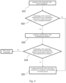
- Fig. 3 is a flow chart showing the general working process of a release device according to an exemplary embodiment.
- the storage module 141 pre-stores parameters such as the first power consumption threshold, the first predetermined timing, and the reference range of power consumption.
- the first predetermined timing may be 0.5-1.5 s, for example, 1 s, since the release process begins.
- the first power consumption threshold may be within a range of 0.2-2.2 mAs, for example, 1 mAs.
- the reference range of power consumption may be in a range of 1-24 mAs, and preferably 2-16 mAs.
- the working process of the release system for releasing the implant is as follows:
- Step S1 The process of Step S1 is specifically as follows:
- the control unit 140 of the release device can detect and distinguish the current environment of the release circuit S, and select different release modes (i.e., the first release mode or the second release mode) according to the current environment. This effectively avoids the "one-size-fits-all" standard for detection of release state, improves the accuracy of judgment, and reduces misjudgment.
- Fig. 4 is a flow chart of the first release mode according to an exemplary embodiment.
- the storage module pre-stores a first predetermined current value that is an index for determining whether the release area is about to break.
- the control unit further pre-stores a second predetermined timing, a third predetermined timing, a second power consumption threshold and a first predetermined time duration.
- the first predetermined current value may be in a range of 0.1-0.8 mA, such as 0.2 mA; the second predetermined timing may be in a range of 5-8 s, such as 7.5 s, since the beginning of the release process; the third predetermined timing may be in a range of 8-13 s, such as 10 s, since the beginning of the release process; the second power consumption threshold may be in a range of 2-5.4 mAs, such as 3 mAs; the first predetermined time duration may be in a range of 0.5-1.8 s, such as 1 s.
- the process of the first release mode is as follows:
- control unit is configured to control the power supply assembly to stop supplying power to the release circuit at the third predetermined timing. That is, the release process is preferably to be suspended at the third predetermined timing.
- the control unit determines whether the first power consumption reaches the second power consumption threshold at a timing between the second predetermined timing and the thrid predetermined timing. In this way, the workload of the control unit can be reduced.
- Fig. 5 is a flow chart of the second release mode according to an exemplary embodiment.
- the control unit pre-stores a second predetermined current value, a fourth predetermined timing, a fifth predetermined timing, a third power consumption threshold, a fourth power consumption threshold and a second predetermined time duration.
- the second predetermined current value is greater than the first predetermined current value, and may be in a range of 0.2-1.8 mA, such as 0.6 mA.
- the fourth predetermined timing may be in a range of 7.5-9.5 s, such as 8.5 s, since the beginning of the release process.
- the fifth predetermined timing may be in a range of 8-13 s, such as 10 s, since the beginning of the release process.
- the third power consumption threshold may be in a range of 2.2-5.4 mAs, such as 3 mAs.
- the fourth power consumption is greater than the third power consumption threshold, and may be in a range of 2.2-5.4 mAs, such as 3.4 mAs.
- the second predetermined time duration may be in a range of 0.5-2.4 s, such as 1 s.
- the process of the second release mode is as follows:
- the control unit determines whether the third release mode to be excuted according to the second power consumption or the third power consumption. That is, if the release device selects the first release mode for the release process to be performed for the first time, the control unit determines whether the second power consumption is within the reference range of power consumption; if so, it is determined to execute the third release mode, if not, it is determined that release process is terminated. If the release device selects the second release mode for the release process to be performed for the first time, the control unit determines whether the third power consumption is within the reference range of power consumption; if so, it is determined to execute the third release mode, if not, it is determined that the release process is terminated.
- the control unit is configured to determine whether the release process is to be performed for the second time according to the power consumption of the release circuit when the release process performed for the first time is suspended, which can reduce the unnecessary suffering of the patient. This is because if the power consumption of the release circuit is less than the minimum value of the reference range of power consumption when the release process performed for the first time is suspended, it means that the current of the release circuit is small, which may be due to poor release environment or short-circuiting of the release circuit; if the power consumption of the relase circuit is greater than the maximum value of the reference range of power consumption when release process performed for the first time is suspended, it means that the current of the release circuit is large, and a short circuit may have occurred. The existence of these problems will cause the release system to fail to complete the release process, thereby eliminating the need for a release process to be perfomed for the second time.
- Fig. 6 is a flow chart of the third release mode according to an exemplary embodiment.
- the control unit pre-stores a third predetermined current value, a sixth predetermined timing, a fifth power consumption threshold and a third predetermined time duration.
- the third predetermined current value may be in a range of 0.1-0.6 mA, such as 0.2 mA.
- the sixth predetermined timing may be in a range of 8-12 s, such as 10 s, since the beginning of the third predetermined mode.
- the fifth power consumption threshold may be in a range of 1.2-4.5 mAs, such as 2 mAs.
- the third predetermined time duration may be in a range of 0.2-2.4 s, such as 1 s.
- the control unit 140 Before executing the third release mode, preferably the control unit 140 clears the previously stored power consumption (i.e., the second power consumption or the third power consumption), so that the power consumption calculated by the control unit after the third relase mode is excuted is actually the power consumption of the release circuit in the third relase mode. As shown in Fig. 6 , the process of the third release mode is as follows:
- Step S42 if the fourth power consumption is less than the fifth power consumption threshold, the control unit can determine that the first release mode is terminated, and further determine that the release process is terminated.
- Step S45 if the timing for comparison is after the sixth predetermined timing, it means that the current of the release circuit has not decreased to the third predetermined current value before the sixth predetermined timing, and the control unit determines that the second release mode is terminated, and further determines that the release process is terminated.
- Step S44 and Step S45 in Fig. 6 can also be interchanged.
- the process of the third release mode is as follows:
- the current output by the constant current source 111 to the release circuit may be in a range of 1.2-3.0 mA, for example, 1.8 mA.
- an embodiment of the present invention further provides a release system.
- the release system includes a release device 100 and a push rod 200.
- the push rod 200 is connected to the power supply assembly 110 of the release device 100, and the power supply assembly 110 is configured to supply power to the positive and negative electrodes of the push rod 200 to form a release circuit S.
- the power supply assembly 110 has a positive electrode and a negative electrode.
- the push rod 200 includes a first electrical conductor 210 and a second electrical conductor 220.
- the proximal end of the first electrical conductor 210 is connected to the negative electrode of the power supply assembly 110.
- the second conductor 220 includes a conductive area 221 and a release area 222 that are connected to each other.
- the proximal end of the conductive area 221 is connected to the positive electrode of the power supply assembly 110.
- the proximal end of the first electrical conductor 210 is formed as the negative electrode of the push rod 200
- the proximal end of the conductive area 221 of the second electrical conductor 220 is formed as the positive electrode of the push rod 200.
- the release area 222 is disposed at the distal end of the conductive area 221, and is connected to the second end through an electrolyte such as body fluid to form the release circuit S.
- proximal end and distal end refer to relative orientations, relative positions and directions of elements relative to each other from the perspective of the doctor operating the medical instruments.
- proximal end and distal end are not restrictive, the “proximal end” generally refers to the end of the medical device that is close to the doctor during normal operation, while the “distal end” generally refers to the end that enters the patient's body first.
- the first electrical conductor 210 and the second electrical conductor 220 are arranged one sleeved over another.
- the first electrical conductor 210 has a columnar body and has an inner cavity axially extending therethrough.
- the conductive area 221 of the second electrical conductor 220 is in the inner cavity, the release area 222 extends to the outside of the inner cavity.
- An insulation 230 is further disposed between the conductive area 221 and the first electrical conductor 210.
- an embodiment of the present invention further provides a therapeutic device.
- the therapeutic device includes a medical implant 300 and the aforementioned release system.
- the medical implant 300 is configued to connect to the release system, and can be released from the release system under predetermined conditions. More specifically, the medical implant 300 is connected to the release area 222 of the push rod 200.
- the medical implant 300 described here includes, but is not limited to, a coil.
- the medical implant 300 can be sent into the lumen where the intracranial aneurysm locates by the push rod 200, and then the release device 100, the push rod 200 and the body fluid together form a release circuit S, to which the power supply assembly 110 of the release device 100 supplies power so as to break the release area 222 to complete the relase of the medical implant 300.
- the medical implant 300 may be a coil or a stent.
- the therapeutic device provided in this embodiment adopts a self-loop structure, so that there is no need to insert conductive needles or place electrodes on the patient's body, thereby reducing the suffering of the patient.
- an embodiment of the present invention also provides a release method including the following steps:
- Whether the release process is successful can be determined according to whether the power consumption reaches a predetermined power consumption threshold and whether the accumulated time dration reaches the predetermined time duration; if both so, it is determined that the release process of the release system is successful.
- the predetermined current value is set according to the detection result about the present power consumption of the release circuit.
- the first predetermined current value is set.
- the second predetermined current value is set.
- the first predetermined current value is less than the second predetermined current value.
- the first predetermined current value is less than the second predetermined current value.
- the release environments are distinguished into a low-current environment and a high-current environment.
- a first predetermined current value is set in the low-current environment. Whether the release process is successful can be determined according to whether the present power consumption of the release circuit reaches a predetermined power consumption threshold and whether the accumulated time dration over which the current of the release circuit is less than or equal to the first predetermined current value reaches the predetermined time duration; if both so, it is determined that the release process of the release system is successful.
- a second predetermined current value (greater than the first predetermined current value in the low-current environment) is set in the high-current environment.
- Whether the release process is successful can be determined according to whether the present power consumption of the release circuit reaches a predetermined power consumption threshold and whether the accumulated time dration over which the current of the release circuit is less than or equal to the second predetermined current value reaches the predetermined time duration; if both so, it is determined that the release process of the release system is successful.
- the release process under a low-current environment and the release process under a high-current environment are respectively defined as a first release mode and a second release mode (the names of the two can also be interchanged).
- the release process under the first release mode or the second release mode is to be performed for the first time.
- the release method includes the following steps:
- a third release mode is further included in the release method. If the release process is determined to be not successful in Step S2, in additional to the aforementioned steps, the relase method further includes:
- the control unit will store the power consumption of the release circuit at a predetermined timing, and determine whether the third release mode is to be excuted so that the release process is to be performed for the second time according to the power consumption of the release circuit at the predetermined timing.
- Step S1 the first release mode or the second release mode is selected for the release process to be performed for the first time based on following steps:
- the process of the first release mode is as follows:
- the first predetermined current value, the second predetermined timing, the third predetermined timing, the second power consumption threshold and the first predetermined time duration are pre-stored for the first release mode.
- the third predetermined timing is after the second predetermined timing.
- the release method when it is determined that the release process is not successful in Step S24, the release method further includes: Step S25: acquiring and storing a second power consumption, which refers to the power consumption of the release circuit in the time period from the beginning of the release process to the third predetermined timing, and stopping supplying power to the release circuit to suspend the release process.
- Step S25 acquiring and storing a second power consumption, which refers to the power consumption of the release circuit in the time period from the beginning of the release process to the third predetermined timing, and stopping supplying power to the release circuit to suspend the release process.
- the process of the second release mode is as follows:
- the second predetermined current value, the fourth predetermined timing, a fifth predetermined timing, the third power consumption threshold, the fourth power consumption threshold and the second predetermined time duration are pre-stored for the second release mode.
- the fifth predetermined timing is after the fourth predetermined timing, and the fourth power consumption threshold is greater than the third power consumption threshold.
- the release method when it is determined that the release process is not successful in Step S35, the release method further includes: Step S36: supplying power to the release circuit until the fifth predetermined timing is reached, and determining that the release process is successful at the fifth predetermined timing.
- a reference range of power consumption is also pre-stored according to the release method. It is to be determined whether the stored power consumption is within the reference range of power consumption; if not, it is determined that the release process is terminated, and if so, it is determined that the third release mode is to be executed.
- This embodiment is an alternative solution provided on the basis that the release process is not successful in both the first release mode and the second release mode, and the release process can be preformed in the third release mode.
- the process of the third release mode is as follows:
- the third predetermined current value, the sixth predetermined timing, the fifth power consumption threshold and a third predetermined time duration are pre-stored.
- Step S42 when it is determined that the fourth power consumption is greater than or equal to the fifth power consumption threshold in Step S42, it is directed to Step S43 and Step S44.
- Step S44 and Step S45 in Fig. 6 can also be interchanged.
- the process of the third release mode is as follows:
Landscapes
- Health & Medical Sciences (AREA)
- Surgery (AREA)
- Life Sciences & Earth Sciences (AREA)
- Medical Informatics (AREA)
- Animal Behavior & Ethology (AREA)
- Vascular Medicine (AREA)
- Reproductive Health (AREA)
- Engineering & Computer Science (AREA)
- Biomedical Technology (AREA)
- Heart & Thoracic Surgery (AREA)
- Veterinary Medicine (AREA)
- Molecular Biology (AREA)
- Nuclear Medicine, Radiotherapy & Molecular Imaging (AREA)
- General Health & Medical Sciences (AREA)
- Public Health (AREA)
- Neurosurgery (AREA)
- Power Sources (AREA)
- Emergency Protection Circuit Devices (AREA)
- Control Of Electric Motors In General (AREA)
- Charge And Discharge Circuits For Batteries Or The Like (AREA)
- Surgical Instruments (AREA)
Applications Claiming Priority (2)
| Application Number | Priority Date | Filing Date | Title |
|---|---|---|---|
| CN202010506601.5A CN113749717B (zh) | 2020-06-05 | 2020-06-05 | 解脱装置、系统及方法、治疗装置 |
| PCT/CN2021/108016 WO2021244671A1 (zh) | 2020-06-05 | 2021-07-23 | 解脱装置、系统及方法、治疗装置 |
Publications (2)
| Publication Number | Publication Date |
|---|---|
| EP4162884A1 true EP4162884A1 (de) | 2023-04-12 |
| EP4162884A4 EP4162884A4 (de) | 2023-11-15 |
Family
ID=78785049
Family Applications (1)
| Application Number | Title | Priority Date | Filing Date |
|---|---|---|---|
| EP21818783.9A Withdrawn EP4162884A4 (de) | 2020-06-05 | 2021-07-23 | Freisetzungsvorrichtung, system und verfahren sowie therapeutische vorrichtung |
Country Status (5)
| Country | Link |
|---|---|
| US (1) | US20230329718A1 (de) |
| EP (1) | EP4162884A4 (de) |
| JP (1) | JP2023531159A (de) |
| CN (1) | CN113749717B (de) |
| WO (1) | WO2021244671A1 (de) |
Cited By (1)
| Publication number | Priority date | Publication date | Assignee | Title |
|---|---|---|---|---|
| WO2024177844A1 (en) * | 2023-02-21 | 2024-08-29 | Stryker Corporation | Vaso-occlusive electrolytic detachment detection |
Family Cites Families (17)
| Publication number | Priority date | Publication date | Assignee | Title |
|---|---|---|---|---|
| US7410482B2 (en) * | 1998-09-04 | 2008-08-12 | Boston Scientific-Scimed, Inc. | Detachable aneurysm neck bridge |
| US6397850B1 (en) * | 2000-02-09 | 2002-06-04 | Scimed Life Systems Inc | Dual-mode apparatus and method for detection of embolic device detachment |
| US20030176857A1 (en) * | 2000-07-26 | 2003-09-18 | Lee Kyu Ho | Assembly for embolic treatments |
| JP4421444B2 (ja) * | 2004-10-28 | 2010-02-24 | 株式会社カネカ | 医療用デバイス用高周波電源装置 |
| WO2009012057A2 (en) * | 2007-07-13 | 2009-01-22 | Boston Scientific Scimed, Inc. | Hybrid and portable power supplies for electrolytically detaching implantable medical devices |
| CA2694027A1 (en) * | 2007-07-20 | 2009-01-29 | Boston Scientific Scimed, Inc. | Power supply using time varying signal for electrolytically detaching implantable device |
| CA2692962C (en) * | 2007-07-27 | 2016-09-13 | Microvention, Inc. | Detachable coil incorporating stretch resistance |
| US20090143786A1 (en) * | 2007-12-03 | 2009-06-04 | Boston Scientific Scimed, Inc. | Implantable device with electrolytically detachable junction having multiple fine wires and method of introduction |
| EP2240093B1 (de) * | 2008-01-04 | 2013-04-24 | Boston Scientific Scimed, Inc. | Ablösemechanismen für implantierbare vorrichtungen |
| JP2016209620A (ja) * | 2010-06-13 | 2016-12-15 | アンジオメトリックス コーポレーション | 血管内腔の情報を決定し、医療用デバイスをガイドするための方法およびシステム |
| CN102715930A (zh) * | 2011-10-25 | 2012-10-10 | 北京泰杰伟业科技有限公司 | 一种用于栓塞用弹簧圈的电解脱控制器 |
| US9855050B2 (en) * | 2014-09-19 | 2018-01-02 | DePuy Synthes Products, Inc. | Vasculature occlusion device detachment system with tapered corewire and single loop fuse detachment |
| US10828039B2 (en) * | 2016-06-27 | 2020-11-10 | Covidien Lp | Electrolytic detachment for implantable devices |
| CN106451798A (zh) * | 2016-09-20 | 2017-02-22 | 宁德时代新能源科技股份有限公司 | 一种启动方法和装置 |
| CN108400727B (zh) * | 2017-02-07 | 2019-12-13 | 苏州宝时得电动工具有限公司 | 电动工具控制方法、装置及电动工具 |
| CN110874094A (zh) * | 2018-09-04 | 2020-03-10 | 西门子(中国)有限公司 | 软启动器的检测装置和检测系统 |
| CN209678602U (zh) * | 2018-12-29 | 2019-11-26 | 微创神通医疗科技(上海)有限公司 | 电解脱装置及电解脱系统 |
-
2020
- 2020-06-05 CN CN202010506601.5A patent/CN113749717B/zh active Active
-
2021
- 2021-07-23 WO PCT/CN2021/108016 patent/WO2021244671A1/zh not_active Ceased
- 2021-07-23 EP EP21818783.9A patent/EP4162884A4/de not_active Withdrawn
- 2021-07-23 JP JP2022574369A patent/JP2023531159A/ja active Pending
- 2021-07-23 US US18/008,299 patent/US20230329718A1/en not_active Abandoned
Cited By (1)
| Publication number | Priority date | Publication date | Assignee | Title |
|---|---|---|---|---|
| WO2024177844A1 (en) * | 2023-02-21 | 2024-08-29 | Stryker Corporation | Vaso-occlusive electrolytic detachment detection |
Also Published As
| Publication number | Publication date |
|---|---|
| CN113749717B (zh) | 2023-09-29 |
| EP4162884A4 (de) | 2023-11-15 |
| CN113749717A (zh) | 2021-12-07 |
| US20230329718A1 (en) | 2023-10-19 |
| WO2021244671A1 (zh) | 2021-12-09 |
| JP2023531159A (ja) | 2023-07-21 |
Similar Documents
| Publication | Publication Date | Title |
|---|---|---|
| EP2521504B1 (de) | Vorrichtung umfassend einen sensor und ein schaltbares gerät zur therapeutischen energiezufuhr | |
| JP4780492B2 (ja) | 塞栓療器の分離検出方法 | |
| AU2012303701B2 (en) | System and method for locating and identifying functional nerves innervating wall of arteries and catheters for same | |
| US5643254A (en) | Endovascular embolic device detachment detection method | |
| EP1370326B1 (de) | Defibrillator mit detektion kardiopulmonarer wiederbelebung | |
| JP4787990B2 (ja) | インプラント可能なデバイスの電気的な位置決め離脱システム | |
| EP3771475A1 (de) | Blasendetektor am proximalen ende eines katheters mit ausfallsicherem mechanismus | |
| JP2005527319A (ja) | 浸潤麻酔を用いる電気外科手術 | |
| JP2010534087A (ja) | 移植可能装置を電解作用により分離するための時間変化信号を用いた電源 | |
| JP2018500092A (ja) | Cpr中の心律動をモニタリングする装置 | |
| JP2017536918A (ja) | デュアルecg解析アルゴリズムを用いた自動体外式除細動器(aed)の解析任意選択ボタン | |
| WO2020063455A1 (zh) | 电解脱机构以及电解脱装置 | |
| EP4162884A1 (de) | Freisetzungsvorrichtung, system und verfahren sowie therapeutische vorrichtung | |
| JP2004065529A (ja) | 血圧制御装置 | |
| WO2022095927A1 (zh) | 起搏控制方法、起搏控制装置及医疗设备 | |
| JP2011512945A (ja) | 植え込み型除細動システムを使用する心房除細動 | |
| EP4186445A1 (de) | Freisetzungsvorrichtung, freisetzungssystem, freisetzungsverfahren und behandlungsvorrichtung | |
| CN115645655B (zh) | 心包腔积液引流装置及心脏压塞缓解方法 | |
| US20210220648A1 (en) | Nerve stimulation apparatus and nerve stimulation method | |
| EP4596031A1 (de) | Defibrillationsvorrichtungen | |
| JPS6157793B2 (de) | ||
| KR20110075203A (ko) | 마취상태가 디스플레이 가능한 마취액주입장치 | |
| JP2016067574A (ja) | 神経刺激装置 | |
| CN120242314A (zh) | 神经电刺激电极及神经电刺激系统 | |
| JPH11299903A (ja) | 体内埋込型薬液投与装置 |
Legal Events
| Date | Code | Title | Description |
|---|---|---|---|
| STAA | Information on the status of an ep patent application or granted ep patent |
Free format text: STATUS: THE INTERNATIONAL PUBLICATION HAS BEEN MADE |
|
| PUAI | Public reference made under article 153(3) epc to a published international application that has entered the european phase |
Free format text: ORIGINAL CODE: 0009012 |
|
| STAA | Information on the status of an ep patent application or granted ep patent |
Free format text: STATUS: REQUEST FOR EXAMINATION WAS MADE |
|
| 17P | Request for examination filed |
Effective date: 20221209 |
|
| AK | Designated contracting states |
Kind code of ref document: A1 Designated state(s): AL AT BE BG CH CY CZ DE DK EE ES FI FR GB GR HR HU IE IS IT LI LT LU LV MC MK MT NL NO PL PT RO RS SE SI SK SM TR |
|
| XX | Miscellaneous (additional remarks) |
Free format text: THE FILING DATE OF THE INTERNATIONAL APPLICATION IS WITHIN TWO MONTHS FROM THE DATE OF EXPIRATION OF THE PRIORITY PERIOD (R. 26BIS.3 PCT). |
|
| A4 | Supplementary search report drawn up and despatched |
Effective date: 20231013 |
|
| RIC1 | Information provided on ipc code assigned before grant |
Ipc: A61B 17/12 20060101AFI20231009BHEP |
|
| STAA | Information on the status of an ep patent application or granted ep patent |
Free format text: STATUS: THE APPLICATION HAS BEEN WITHDRAWN |
|
| 18W | Application withdrawn |
Effective date: 20240419 |