EP4162256B1 - Vorrichtung zum nachweis von stoffen - Google Patents
Vorrichtung zum nachweis von stoffen Download PDFInfo
- Publication number
- EP4162256B1 EP4162256B1 EP21723244.6A EP21723244A EP4162256B1 EP 4162256 B1 EP4162256 B1 EP 4162256B1 EP 21723244 A EP21723244 A EP 21723244A EP 4162256 B1 EP4162256 B1 EP 4162256B1
- Authority
- EP
- European Patent Office
- Prior art keywords
- matter
- light
- detection zone
- arrangement
- light beams
- Prior art date
- Legal status (The legal status is an assumption and is not a legal conclusion. Google has not performed a legal analysis and makes no representation as to the accuracy of the status listed.)
- Active
Links
Images


Classifications
-
- G—PHYSICS
- G01—MEASURING; TESTING
- G01N—INVESTIGATING OR ANALYSING MATERIALS BY DETERMINING THEIR CHEMICAL OR PHYSICAL PROPERTIES
- G01N21/00—Investigating or analysing materials by the use of optical means, i.e. using sub-millimetre waves, infrared, visible or ultraviolet light
- G01N21/17—Systems in which incident light is modified in accordance with the properties of the material investigated
- G01N21/25—Colour; Spectral properties, i.e. comparison of effect of material on the light at two or more different wavelengths or wavelength bands
- G01N21/31—Investigating relative effect of material at wavelengths characteristic of specific elements or molecules, e.g. atomic absorption spectrometry
- G01N21/39—Investigating relative effect of material at wavelengths characteristic of specific elements or molecules, e.g. atomic absorption spectrometry using tunable lasers
-
- B—PERFORMING OPERATIONS; TRANSPORTING
- B07—SEPARATING SOLIDS FROM SOLIDS; SORTING
- B07C—POSTAL SORTING; SORTING INDIVIDUAL ARTICLES, OR BULK MATERIAL FIT TO BE SORTED PIECE-MEAL, e.g. BY PICKING
- B07C5/00—Sorting according to a characteristic or feature of the articles or material being sorted, e.g. by control effected by devices which detect or measure such characteristic or feature; Sorting by manually actuated devices, e.g. switches
- B07C5/34—Sorting according to other particular properties
- B07C5/342—Sorting according to other particular properties according to optical properties, e.g. colour
-
- G—PHYSICS
- G01—MEASURING; TESTING
- G01J—MEASUREMENT OF INTENSITY, VELOCITY, SPECTRAL CONTENT, POLARISATION, PHASE OR PULSE CHARACTERISTICS OF INFRARED, VISIBLE OR ULTRAVIOLET LIGHT; COLORIMETRY; RADIATION PYROMETRY
- G01J3/00—Spectrometry; Spectrophotometry; Monochromators; Measuring colours
- G01J3/28—Investigating the spectrum
- G01J3/2823—Imaging spectrometer
-
- G—PHYSICS
- G01—MEASURING; TESTING
- G01N—INVESTIGATING OR ANALYSING MATERIALS BY DETERMINING THEIR CHEMICAL OR PHYSICAL PROPERTIES
- G01N21/00—Investigating or analysing materials by the use of optical means, i.e. using sub-millimetre waves, infrared, visible or ultraviolet light
- G01N21/17—Systems in which incident light is modified in accordance with the properties of the material investigated
- G01N21/25—Colour; Spectral properties, i.e. comparison of effect of material on the light at two or more different wavelengths or wavelength bands
- G01N21/31—Investigating relative effect of material at wavelengths characteristic of specific elements or molecules, e.g. atomic absorption spectrometry
- G01N21/35—Investigating relative effect of material at wavelengths characteristic of specific elements or molecules, e.g. atomic absorption spectrometry using infrared light
- G01N21/3563—Investigating relative effect of material at wavelengths characteristic of specific elements or molecules, e.g. atomic absorption spectrometry using infrared light for analysing solids; Preparation of samples therefor
-
- G—PHYSICS
- G01—MEASURING; TESTING
- G01N—INVESTIGATING OR ANALYSING MATERIALS BY DETERMINING THEIR CHEMICAL OR PHYSICAL PROPERTIES
- G01N21/00—Investigating or analysing materials by the use of optical means, i.e. using sub-millimetre waves, infrared, visible or ultraviolet light
- G01N21/17—Systems in which incident light is modified in accordance with the properties of the material investigated
- G01N21/25—Colour; Spectral properties, i.e. comparison of effect of material on the light at two or more different wavelengths or wavelength bands
- G01N21/31—Investigating relative effect of material at wavelengths characteristic of specific elements or molecules, e.g. atomic absorption spectrometry
- G01N21/35—Investigating relative effect of material at wavelengths characteristic of specific elements or molecules, e.g. atomic absorption spectrometry using infrared light
- G01N21/359—Investigating relative effect of material at wavelengths characteristic of specific elements or molecules, e.g. atomic absorption spectrometry using infrared light using near infrared light
-
- G—PHYSICS
- G01—MEASURING; TESTING
- G01J—MEASUREMENT OF INTENSITY, VELOCITY, SPECTRAL CONTENT, POLARISATION, PHASE OR PULSE CHARACTERISTICS OF INFRARED, VISIBLE OR ULTRAVIOLET LIGHT; COLORIMETRY; RADIATION PYROMETRY
- G01J3/00—Spectrometry; Spectrophotometry; Monochromators; Measuring colours
- G01J3/28—Investigating the spectrum
- G01J3/2823—Imaging spectrometer
- G01J2003/2826—Multispectral imaging, e.g. filter imaging
-
- G—PHYSICS
- G01—MEASURING; TESTING
- G01N—INVESTIGATING OR ANALYSING MATERIALS BY DETERMINING THEIR CHEMICAL OR PHYSICAL PROPERTIES
- G01N21/00—Investigating or analysing materials by the use of optical means, i.e. using sub-millimetre waves, infrared, visible or ultraviolet light
- G01N21/84—Systems specially adapted for particular applications
- G01N2021/845—Objects on a conveyor
-
- G—PHYSICS
- G01—MEASURING; TESTING
- G01N—INVESTIGATING OR ANALYSING MATERIALS BY DETERMINING THEIR CHEMICAL OR PHYSICAL PROPERTIES
- G01N21/00—Investigating or analysing materials by the use of optical means, i.e. using sub-millimetre waves, infrared, visible or ultraviolet light
- G01N21/84—Systems specially adapted for particular applications
- G01N21/85—Investigating moving fluids or granular solids
- G01N2021/8592—Grain or other flowing solid samples
-
- G—PHYSICS
- G01—MEASURING; TESTING
- G01N—INVESTIGATING OR ANALYSING MATERIALS BY DETERMINING THEIR CHEMICAL OR PHYSICAL PROPERTIES
- G01N2201/00—Features of devices classified in G01N21/00
- G01N2201/06—Illumination; Optics
- G01N2201/061—Sources
- G01N2201/06113—Coherent sources; lasers
-
- G—PHYSICS
- G01—MEASURING; TESTING
- G01N—INVESTIGATING OR ANALYSING MATERIALS BY DETERMINING THEIR CHEMICAL OR PHYSICAL PROPERTIES
- G01N2201/00—Features of devices classified in G01N21/00
- G01N2201/10—Scanning
- G01N2201/104—Mechano-optical scan, i.e. object and beam moving
Definitions
- the present invention relates to an apparatus for detecting matter and more specifically to such an apparatus comprising a spectroscopy system and a laser triangulation system.
- manual identification of objects by a person may be employed to advantage when a limited number of objects are to be identified, sorted and classified. The person in question may then, based on his/her knowledge identify and classify the objects concerned.
- This type of manual identification is however monotonous and prone to errors. Also, the experience level of the operator will significantly influence the results of the operation performed by the operator. Moreover, manual identification of the above kind suffers from low identification speeds.
- Machines of the above kind generally has some form of sensor that is used for identifying the objects of interest.
- an optical sensor in form of a spectral sensor may be employed to determine the quality of harvested fruits and vegetables.
- a spectral sensor may be employed to determine the material of objects that are to be recycled.
- a plurality of sensors is typically required.
- the use of more than one sensor generally results in that the machines will have to be made larger in order to be able to fit the further sensors and associated entities required.
- the footprint of the machines increases.
- the increased footprint resulting in that valuable industry space that might be used for other purposes is needed for installing the machines.
- the use of further sensors may result in that the sensors interfere with each other if not positioned sufficiently far away from each other.
- DE 196 50 705 A1 discloses a method and an arrangement for implementation of more compact and inexpensive multisensory cameras in which different image sensors, being sensitive to different properties, are stacked vertically on top of each other in a common beam path.
- the individual stacked image sensors are aligned such that corresponding pixels of the respective image sensors views the same portion of the object being viewed.
- WO 01/07950 A1 discloses a sorting device, provided with an inspection unit, where products to be sorted are inspected on their acceptability.
- US 2016/0263624 A1 discloses an apparatus for detecting matter in which a plurality of objects is fed into a detection region. The objects are illuminated in the detection region and light having passed through the objects are detected.
- US 2004/0027574 A1 discloses an apparatus and methods for sensing the presence of bright white paper on a conveyor of a paper sorting system by utilizing fluorescence triggered by ultraviolet light.
- an object of the present invention is to provide an apparatus for detecting matter which is compact and hence requires less installation space.
- Another object is to provide such an apparatus enabling efficient detection of matter by using a spectroscopy system and a laser triangulation system.
- Another object is to provide such an apparatus enabling enhanced detection of matter.
- an apparatus for detecting matter comprising: a light source arrangement adapted to emit a first set of light beams and a second set of light beams towards a first detection zone through which the matter is provided, a spectroscopy system including a spectrometer, wherein the spectroscopy system is adapted to receive and analyse light which is reflected and/or scattered by matter in the first detection zone, wherein the received light of the spectroscopy system originates from the first and second sets of light beams, and a laser triangulation system including, a laser arrangement adapted to emit a line of laser light towards a second detection zone through which the matter is provided, and a camera-based sensor arrangement configured to receive and analyse light which is reflected and/or scattered by matter in the second detection zone, wherein the received light of the camera-based sensor arrangement originates from the line of laser light, wherein the apparatus is configured such that the received light of the spectroscopy system completely intersects the received light of the camera-based sensor arrangement and/
- the apparatus comprises a light source arrangement which is adapted to emit a first set of light beams and a second set of light beams towards a first detection zone through which the matter is provided.
- the light source arrangement is adapted to emit two different separate sets of light beams.
- the first set of light beams and a second set of light beams emitted by the light source arrangement are both emitted towards a first detection zone.
- the term set of light beams may be any type of light, visible or non-visible such as NIR, IR or UV, having an extension other than an infinite decimal beam or ray.
- the set of light beams may mean any bundle or beam of light having a physical extension in space travers to its propagation direction.
- the set of light beams may thus for instance form a beam of parallel light, a beam of non-parallel light, like a diverging or converging beam of light, or a band of light to give a few non-limiting examples.
- the first set of light beams and a second set of light beams will hence reach the first detection zone through which matter is provided.
- the matter is provided through the first detection zone in the sense that the matter is transferred or conveyed through the first detection zone.
- the matter may be provided through the first detection zone in a continuous or intermittent manner.
- the matter may be provided through the first detection zone sequentially or in parallel.
- a single piece of matter or a plurality of pieces of matter may be in the first detection zone at the same time.
- Preferably a plurality of pieces of matter are present simultaneously in the first detection zone.
- the apparatus comprises a spectroscopy system adapted to receive and analyse light which is reflected and/or scattered by matter in the first detection zone.
- the received light of the spectroscopy system is originating or predominantly originating from the first and second sets of light beams. Hence, a limited amount of ambient light may reach the spectroscopy system.
- the spectroscopy system is thus adapted such that it views the first detection zone in order to receive and analyse light which is reflected and/or scattered by matter in the first detection zone.
- Optical elements may be provided between an entry window of the spectroscopy system and the first detection zone to alter a beam path of the light being reflected and/or scattered by matter in the first detection zone.
- the apparatus comprises a laser triangulation system.
- the laser triangulation system includes a laser arrangement adapted to emit a line of laser light towards a second detection zone through which the matter is provided.
- the laser arrangement typically includes one or more laser light sources and optionally optical elements for forming emitted laser light into a line of laser light.
- line of laser light may be any type of laser light, visible or non-visible, having an elongated extension, such that the light forms a line or a line like profile when impinging on a surface.
- the matter is provided through the second detection zone correspondingly to what has been described above in relation to the first detection zone.
- the laser triangulation system includes a camera-based sensor arrangement configured to receive and analyse light which is reflected and/or scattered by matter in the second detection zone.
- the received light of the camera-based sensor arrangement is originating or predominantly originating from the line of laser light. Hence, a limited amount of ambient light may still reach the camera-based sensor arrangement.
- the camera-based sensor arrangement is thus adapted such that it views the second detection zone in order to receive and analyse light which is reflected and/or scattered by matter in the second detection zone.
- the reflected light of the line of laser light will move on the sensor element of the camera-based sensor arrangement in response to a height variation of the matter in the second detection zone.
- the sensor element of the camera-based sensor arrangement is typically an imaging sensor element including an array of light sensitive sensor pixels.
- the received light of the spectroscopy system completely intersects the received light of the camera-based sensor arrangement and/or the line of laser light.
- the particular provision of the spectroscopy system in relation to the camera-based sensor arrangement and/or the laser arrangement allows for a compact system requiring significantly less space.
- the received light of the spectroscopy system i.e. the light originating from the first and second set of light beams and having been reflected and/or scattered by matter in the first detection zone
- the received light of the camera-based sensor arrangement i.e. the light originating from the line of laser light and having been reflected and/or scattered by matter in the second detection zone.
- both the spectroscopy system (and the light source arrangement) and the laser triangulation system may be provided in the same area of the apparatus meaning that both these systems may be provided in a space normally required for a single system. This means that a compact apparatus with enhanced detection capabilities is provided by the present invention.
- the matter is subsequently provided through the first detection zone and the second detection zone.
- This allows for that specific matter provided in the first detection zone may subsequently be correlated to be the same matter when provided in through the second detection zone.
- a compact apparatus with enhanced detection capabilities is provided by the present invention.
- the apparatus may further comprise a focusing arrangement, wherein the focusing arrangement is adapted to direct and focus the first set of light beams and the second set of light beams on a scanning element, wherein the scanning element being adapted to redirect the first and second sets of light beams towards the first detection zone, whereby the first and second set of light beams converge at the first detection zone.
- a focusing arrangement is adapted to direct and focus the first set of light beams and the second set of light beams on a scanning element, wherein the scanning element being adapted to redirect the first and second sets of light beams towards the first detection zone, whereby the first and second set of light beams converge at the first detection zone.
- the scanning element may scan the first and second set of light beams at the first detection zone.
- the scanning element may be one of a rotating polygon mirror and a tilting mirror.
- the light source arrangement may include a first light source adapted to emit the first set of light beams and a second light source adapted to emit the second set of light beams.
- a more intense illumination may be provided at the first detection zone.
- the illumination of the first detection zone may easily be tailored by using different types of light sources having different characteristics as the first and second light sources.
- a more robust apparatus may be achieved. The apparatus may not need to be taken out of operation if one of the first and second light sources fails and may consequently still be operated during exchange of one of the light sources.
- the focusing arrangement may include a first focusing element adapted to direct and focus the first set of light beams on the scanning element and a second focusing element adapted to direct and focus the second set of light beams on the scanning element, which is advantageous in that the first and second sets of light beams may be directed and focused individually on the scanning element.
- the focusing elements may be any optical element capable of focusing and directing the first and/or second sets of light beams.
- the focusing elements may be a combination of a plurality of optical elements acting jointly.
- the focusing elements may direct the first and/or second sets of light beams along a direction of incoming light of the first and/or second sets of light beams.
- the first focusing element may be a lens or a mirror.
- the first focusing element may be a combination of a lens and a mirror.
- the second focusing element may be a lens or a mirror.
- the second focusing element may be a combination of a lens and a mirror.
- the light source arrangement may include a single light source adapted to emit the first set of light beams and the second set of light beams, which is advantageous in that the light source arrangement may be made more energy efficient. Further, the light source arrangement may be made more compact since space may only have to be allocated to a single light source.
- the focusing arrangement may include a first focusing element adapted to direct and focus the first set of light beams on the scanning element and a second focusing element adapted to direct and focus the second set of light beams on the scanning element, which is advantageous in that the first and second sets of light beams may be directed and focused individually on the scanning element.
- the focusing elements may be any optical element capable of focusing and directing the first and/or second sets of light beams.
- the focusing elements may be a combination of a plurality of optical elements acting jointly.
- the focusing elements may direct the first and/or second sets of light beams along a direction of incoming light of the first and/or second sets of light beams.
- the first focusing element may be a lens or a mirror.
- the first focusing element may be a parabolic mirror.
- the first focusing element may be an elliptical mirror or a mirror with a shape optimized to focus light into the first detection zone.
- the first focusing element may be an off-axis parabolic mirror.
- the first focusing element may be a combination of a lens and a mirror.
- the first focusing element may be a combination of a lens and a flat mirror.
- the second focusing element may be a lens or a mirror.
- the second focusing element may be a parabolic mirror.
- the second focusing element may be an elliptical mirror or a mirror with a shape optimized to focus light into the first detection zone.
- the second focusing element may be an off-axis parabolic mirror.
- the second focusing element may be a combination of a lens and a mirror.
- the second focusing element may be a combination of a lens and a flat mirror.
- the spectroscopy system may include a first spectrometer system adapted to analyse light of a first wavelength interval and a second spectrometer system adapted to analyse light of a second wavelength interval, which is advantageous in that spectrometer systems adapted for analysis of a certain wavelength interval may be used. By this arrangement, more sensitive and accurate analysis may be performed.
- the first wavelength interval and the second wavelength interval may overlap or partially overlap.
- the first wavelength interval and the second wavelength interval may be separate intervals.
- the spectroscopy system may include a first spectrometer system adapted to analyse light of a first wavelength interval, a second spectrometer system adapted to analyse light of a second wavelength interval and a third spectrometer system adapted to analyse light of a third wavelength interval.
- the spectroscopy system may include a plurality of spectrometer systems adapted to analyse light of a plurality of wavelength intervals.
- the spectroscopy system may be a scanning spectroscopy system, which is advantageous in that accurate analysis ranging over a wavelength interval may be performed on the matter in the first detection zone. Also, an image of the matter in the first detection zone may be acquired, where the image including information form the analysis of the light received by the scanning spectroscopy system.
- the first detection zone and the second detection zone may overlap, which is advantageous in that it may become easier to correlate matter in the first detection zone to corresponding matter in the second detection zone. In other words, it may become easier to determine when a particular piece of matter having passed through the first detection zone passes through the second detection zone.
- This setup is advantageous when the matter is traveling through the first detection zone and/or second detection zone in a random fashion, as is generally the case when the matter is free falling or sliding through the first detection zone and/or second detection zone.
- the first detection zone and the second detection zone may overlap partially.
- the apparatus may further include a first optical filter arranged between the light source arrangement and the first detection zone, the first optical filter counteracting light originating from the first set of light beams and the second set of light beams from reaching the camera-based sensor arrangement.
- This arrangement of the first optical filter may counteract undesired light that otherwise would risk disturbing the camera-based sensor system form reaching the same.
- the provision of the first optical filter is particularly relevant and hence advantageous when the first detection zone and the second detection zone overlap.
- the apparatus may further include a second optical filter arranged between the second detection zone and the camera-based sensor arrangement, the second optical filter counteracts passing of light originating from the first set of light beams, the second set of light beams and ambient light while allowing passage of light originating from the line of laser light.
- This arrangement of the second optical filter may counteract undesired light that otherwise would risk disturbing the camera-based sensor arrangement form reaching the same.
- the provision of the second optical filter is particularly relevant and hence advantageous when the first detection zone and the second detection zone overlap.
- the laser arrangement may further be adapted to emit a further line of laser light towards a second detection zone
- the camera-based sensor arrangement may be further configured to receive and analyse light originating from the further line of laser light which is reflected and/or scattered by matter in the second detection zone.
- a wavelength of light of the further line of laser light may be different form a wavelength of light of the line of laser light.
- the apparatus may further include a third optical filter arranged between the second detection zone and the camera-based sensor system, the second optical filter counteracts passing of light originating from the first set of light beams, the second set of light beams, the laser light and ambient light while allowing passage of light originating from the further line of laser light.
- a third optical filter arranged between the second detection zone and the camera-based sensor system, the second optical filter counteracts passing of light originating from the first set of light beams, the second set of light beams, the laser light and ambient light while allowing passage of light originating from the further line of laser light.
- the camera-based may be configured to receive and analyse light which is reflected and/or scattered by matter in the second detection zone based on different wavelengths.
- the received light originating from the line of laser light and from the further line of laser light may advantageously be directed to different areas of an imaging sensor element of the camera-based sensor system or to different imaging sensor elements of the camera-based sensor system.
- the possibility to analyse light which is reflected and/or scattered by matter in the second detection zone based on different wavelengths brings about that more information about the matter in the second detection zone may be acquired.
- the apparatus may further comprise a processing unit coupled to the spectroscopy system and the camera-based sensor arrangement, wherein the processing unit being configured to determine a first property set pertaining to matter in the first detection zone based on an outputted signal of the spectroscopy system, and wherein the processing unit being configured to determine a second property set pertaining to matter in the second detection zone based on an outputted signal of the camera-based sensor arrangement.
- the provision of a processing unit coupled to the spectroscopy system and the camera-based sensor arrangement brings about that the processing unit may determine properties or a property of matter in the respective first and second detection zones.
- the processing unit may thus receive signals form the spectroscopy system and the camera-based sensor arrangement respectively. The received signals may be based on analysis of the light received by the spectroscopy system and the camera-based sensor arrangement respectively.
- processing unit may be any unit, system or device capable of receiving a signal or signals or data from other entities and to process the received signals or data.
- the processing may for instance include calculating properties or a property based on the received the received signals or data, forwarding of the received signals or data and altering the received signals or data.
- the processing unit may be a single unit or may be distributed over a plurality of devices, such as a plurality of PCs, each having processing capabilities.
- the processing unit may be implemented in hardware or in software.
- the term property set may be any set of data including any type of data.
- the property set may include any number of properties including 0.
- the property set may be an empty set, which for instance may be indicative of a non-presence of matter.
- the first property set may be indicative of at least one of a spectral response of the matter, a material type of the matter, a colour of the matter, a fluorescence of the matter, a ripeness of the matter, a dry matter content of the matter, a water content of the matter, a fat content of the matter, an oil content of the matter, a calorific value of the matter, a presence of bones or fishbones of the matter, a presence of pest, a mineral type of the matter, an ore type of the matter, a defect level of the matter, a detection of hazardous biological materials of the matter, a presence of matter, a non-presence of matter, a detection of multilayer materials of the matter, a detection of fluorescent markers of the matter, a quality grade of the matter, a physical structure of the surface of the matter and a molecular structure of the matter.
- An example of a relevant hazardous biological material that may be detected is mycotoxin.
- the above features of the first property set may be determined in specific combinations which may be useful for detecting matter in the first detection zone. Examples of applications where such combinations are useful are sorting of pet food, detection of fishbones in fillets, paper sorting using visible and NIR spectroscopy, removal of foreign material and shells from pistachios, recycling of polymers to give a few non-limiting examples.
- the second property set may be indicative of at least one of a height of the matter, a height profile of the matter, a 3D map of the matter, an intensity profile of reflected and/or scattered light, a volume centre of the matter, an estimated mass centre of the matter, an estimated weight of the matter, an estimated material of the matter a presence of matter, a non-presence of matter, a detection of isotropic and anisotropic light scattering of the matter, a structure and quality of wood, a surface roughness and texture of the matter and an indication of presence of fluids in the matter.
- Examples of a relevant fluids are oil and water in food products.
- the above features of the second property set may be determined in specific combinations which may be useful for detecting matter in the second detection zone. Examples of applications where such combinations are useful are glass sorting and quartz sorting to give a few non-limiting examples.
- the processing unit may be further configured to receive an input indicative of a viewing angle of the camera-based sensor arrangement with respect to the second detection zone, and to compensate for the viewing angle of the camera-based sensor arrangement when determining the second property set, which is advantageous in that a more accurate subsequent sorting or ejection of the matter may be achieved.
- the height of the matter in the second detection zone may be compensated for when determining a position of the matter in the second detection zone.
- a subsequent sorting or ejection operation may affect or influence the matter in a location counteracting wrongful sorting or ejection.
- a sorter or ejector may impinge on matter at its estimated mass center thereby reducing the risk of for instance slipping or tumbling of the matter.
- An ejector may be configured with valve image processing steps for reducing or minimizing the compressed air consumption and energy consumption while keeping optimal sorting yield and sorting loss.
- the processing unit may be configured to receive an input indicative of a geometry of the laser arrangement and the camera-based sensor arrangement with respect to the second detection zone.
- the processing unit may be configured to compensate for the geometry of the laser arrangement and the camera-based sensor arrangement with respect to the second detection zone when determining the second property set.
- the apparatus may further comprise an ejection arrangement coupled to the processing unit, wherein the ejection arrangement is adapted to eject and sort matter into a plurality of fractions in response to receiving a signal form the processing unit based on the determined first property set and/or the determined second property set, the ejection arrangement being adapted to eject and sort said matter by means of at least one of a jet of compressed air, a jet of pressurized water, a mechanical finger, a bar of jets of compressed air, a bar of jets of pressurized water, a bar of mechanical fingers, a robotic arm and a mechanical diverter.
- the apparatus may eject and thus sort the matter into a plurality of fractions based on the determined first property set and/or the determined second property set.
- the matter may be sorted based on analysis performed by the spectroscopy system and/or the laser triangulation system.
- the plurality of fractions may be based on any of the determined properties.
- the fractions may for instance be based on material or colour.
- One faction may correspond to matter that is to be discarded or scrapped.
- the ejection and sorting may be executed by a jet of compressed air, a jet of pressurized water, a mechanical finger, a bar of jets of compressed air, a bar of jets of pressurized water, a bar of mechanical fingers, a robotic arm or a mechanical diverter.
- the matter may be analyzed online by for instance a cloud service.
- the so analyzed matter may then be classified for instance in terms of purity, defect level, average color etc.
- the apparatus may further comprise, a conveyor for conveying matter through the first detection zone and the second detection zone, or a chute, optionally including a vibration feeder, for sliding or freefalling of the matter through the first detection zone and/or the second detection zone.
- the matter may be conveyed through the first detection zone and second detection zone in a controlled manner. Matter conveyed through and analysed in the first detection zone may then be conveyed through and analysed in the second detection zone.
- a controlled conveyance of matter through the first detection zone and the second detection zone matter may be kept track of. Hence, matter in the first detection zone may be correlated or identified as being the same matter in the second detection zone.
- a chute optionally including a vibration feeder
- the matter may be slid or made freefalling through the first detection zone and/or the second detection zone.
- the matter may be slid though the first detection zone and the second detection zone.
- the matter may be made to freefall through the first detection zone and the second detection zone.
- the matter may be slid though the first detection zone and made to freefall through the second detection zone.
- the provision of a chute, optionally including a vibration feeder is advantageous for small bulk object such as grains of different kinds.
- Fig. 1 schematically illustrates an apparatus 100 for detecting matter. Matter 102 is provided through a first detection zone 104 and a second detection zone 106.
- the matter 102 is conveyed through provided through the first detection zone 104 and the second detection zone 106 by means of a conveyor 108.
- the matter 102 may be provided through the the first detection zone 104 and the second detection zone 106 by any suitable means or manually without any technical means. Further, the matter 102 may be provided through the the first detection zone 104 and the second detection zone 106 by sliding or freefalling.
- the conveyor of Fig. 1 is optional.
- the depicted apparatus 100 of Fig. 1 further includes a housing 110 arranged above the first detection zone 104 and the second detection zone 106.
- the housing 110 is arranged above the conveyor 108.
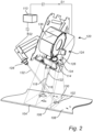
- FIG. 2 schematically discloses a selection of components arranged in the housing 110.
- a light source arrangement 114 adapted to emit a first set of light beams 116 and a second set of light beams 118 towards the first detection zone 104.
- a spectroscopy system 120 adapted to receive and analyse light 122 which is reflected and/or scattered by matter 102 in the first detection zone 104.
- the laser triangulation system 124 includes a laser arrangement 126 adapted to emit a line of laser light 130 towards the second detection zone 106.
- the laser triangulation system 124 includes a camera-based sensor arrangement 128 configured to receive and analyse light 132 which is reflected and/or scattered by matter 102 in the second detection zone 106.
- the depicted apparatus 100 of Fig. 1 further includes an ejection arrangement 112 provided downstream of the first detection zone 104 and the second detection zone 106.
- the ejection arrangement 112 is adapted to eject and sort the matter 102 into a plurality of fractions.
- the ejection arrangement 112 of Fig. 1 is optional.
- the depicted apparatus 100 of Fig. 1 further includes a control cabinet 111 arranged above the conveyor 108.
- the control cabinet 111 includes equipment used for controlling the apparatus 100.
- the equipment typically includes a processing unit 113 or control unit for controlling the conveyor 108, the ejection arrangement 112 and the equipment in the housing 110.
- the processing unit 113 is typically used to determine properties or a property of the matter 102 based on measurement carried out by the equipment in the housing 110.
- FIG. 2 here is conceptually depicted components in the interior of the housing 110 of Fig. 1 .
- Fig. 2 also illustrates a portion of the conveyor 108 including the first detection zone 104 and the second detection zone 106.
- the received light 122 of the spectroscopy system 120 intersects the received light 132 of the camera-based sensor arrangement 128.
- Matter 102 is provided through the first detection zone 104 and the second detection zone 106 by means of the conveyor 108.
- the matter 102 is in the depicted apparatus 100 of Figs. 1 and 2 conveyed through the first detection zone 104 and the second detection zone 106.
- the matter 102 is typically conveyed through the first detection zone 104 and the second detection zone 106 continuously.
- the matter 102 may be conveyed through the first detection zone 104 and the second detection zone 106 in an intermittent manner.
- the matter 102 may be conveyed through the first detection zone 104 fist and subsequently through the second detection zone 106.
- the matter 102 may be conveyed through the second detection zone 106 fist and subsequently through first detection zone 104.
- the laser arrangement 126 includes a line laser which emits the line of laser light 130.
- the laser may be of any suitable kind.
- the laser preferably has a peak wavelength at 660 nm or 640 nm.
- An example of a suitable laser is Z100M18S3-F-660-LP60-PR manufactured by Z-Laser which emits a line of laser light having a wavelength of 660 nm.
- the laser arrangement 126 may be equipped with a thermoelectric cooling device and insulation to withstand a typical ambient temperature of 60°C.
- the line of laser light 130 impinges on the matter 102 in the second detection zone 106, where the light is reflected and/or scattered by the matter 102.
- a portion of the so reflected and/or scattered light 132 typically reaches the camera-based sensor arrangement 128, as schematically illustrated in Fig. 2 .
- the camera-based sensor arrangement 128 will view and consequently image the line of laser light 130 as it impinges on the matter 102 in the second detection zone 106.
- the camera-based sensor arrangement 128 may for instance include a camera of the type C5 manufactured by AT - Automation Technology GmbH.
- a height variation or a presence of the matter 102 in the second detection zone 106 will shift the location of the image of the line of laser light on a sensor element of the camera of the camera-based sensor arrangement 128.
- the shift owing form the angle difference between the field of view of the of the camera of the camera-based sensor arrangement 128 and the line of laser light 130.
- Various properties of the matter 102 in the second detection zone 106 may be determined based on measurements carried out by the camera-based sensor arrangement 128.
- a focusing arrangement 134 is adapted to direct and focus the first set of light beams 116 and the second set of light beams 118 on a scanning element 136.
- the scanning element 136 is adapted to redirect the first and second sets of light beams 116, 118 towards the first detection zone 104. By the arrangement of the scanning element 136 the first and second set of light beams 116, 118 converge at the first detection zone 104 as illustrated in Fig. 2 .
- the depicted scanning element 136 of Fig. 2 is in the form of a rotational polygon mirror.
- first set of light beams 116 and the second set of light beams 118 will occur.
- the first set of light beams 116 and the second set of light beams 118 will hence be scanned across the first detection zone 104 and consequently be scanned across the conveyor 108.
- scanning elements may be used to advantage.
- a scanning mirror hinged about a pivot axis may be used.
- the spectroscopy system 120 is adapted to receive and analyse light 122 which is reflected and/or scattered by matter 102 in the first detection zone 104.
- the light 122 which is reflected and/or scattered by matter 102 in the first detection zone 104 will before entering the spectroscopy system 120 impinge on the scanning element 136, i.e. the polygon mirror, form where the light 122 is directed to an entry window of the spectroscopy system 120 by means of a fixed folding mirror.
- the fixed folding mirror may be located between where the first set of light beams 116 and the second set of light beams 118 exits the focusing arrangement 134.
- the spectroscopy system 120 may include a spectrometer manufactured by Tomra which is able to cope with the required repetition rate.
- the spectrometer may be configured to analyse light in the wavelength interval 400 - 1000 nm.
- the spectrometer may be configured to analyse light in the wavelength interval 500 - 1000 nm.
- the spectrometer may be configured to analyse light in the wavelength interval 1000 - 1900 nm.
- the spectrometer may be configured to analyse light having a wavelength above 900 nm.
- the spectrometer may be configured to analyse light in the wavelength interval 1900 - 2500 nm.
- the spectrometer may be configured to analyse light in the wavelength interval 2700 - 5300 nm.
- the spectrometer may be configured to analyse light in the wavelength interval 900 - 1700 nm.
- the spectrometer may be configured to analyse light in the wavelength interval 700 - 1400 nm.
- the spectrometer may analyse visible light.
- the spectrometer may analyse NIR light.
- the spectrometer may analyse IR light. Different types of spectrometers may be used depending on characteristics of the matter 102 to be detected.
- the spectroscopy system 120 may include a first spectrometer system 120 adapted to analyse light of a first wavelength interval and a second spectrometer system 120 adapted to analyse light of a second wavelength interval.
- a first spectroscopy system 120 may analyse light in the wavelength interval 450 - 800 nm and a second spectroscopy system 120 may analyse light in the wavelength interval 1500 - 1900 nm.
- one spectrometer for visible light may be used in combination with one NIR spectrometer.
- three or more spectroscopy systems 120 may be included in the spectroscopy system 120.
- three or more spectrometers may be used.
- one spectrometer for visible light may be used in combination with two NIR spectrometers.
- the spectroscopy system 120 may be a scanning spectroscopy system 120.
- An example of a suitable scanning spectrometer is manufactured by Tomra.
- Various properties of the matter 102 in the first detection zone 104 may be determined based on measurements carried out by the spectroscopy system 120.
- the depicted apparatus 100 of Figs. 1 and 2 includes a processing unit 113.
- the processing unit 113 is in the depicted apparatus 100 located in the control cabinet 111.
- the processing unit 113 is coupled to the spectroscopy system 120 and the camera-based sensor arrangement 128.
- the coupling between the processing unit 113, the spectroscopy system 120 and the camera-based sensor arrangement 128 is schematically illustrated by broken lines in Fig. 2 .
- the processing unit 113 may be coupled to the spectroscopy system 120 and the camera-based sensor arrangement 128 by any suitable connection, including wired and wireless connections. Any connection capable of transmitting data in any format, digital or analogue, may be used to advantage.
- the processing unit 113 of the depicted apparatus 100 is configured to determine a first property set pertaining to matter 102 in the first detection zone 106.
- the first property set may be any set of data including any type of data.
- the first property set may include any number of properties.
- the first property set is determined based on an outputted signal S1 of the spectroscopy system 120.
- the signal S1 may include any kind of data, proceed or raw.
- the processing unit 113 is thus configured to receive and analyse data based on the outputted signal S1 of the spectroscopy system 120 and to determine a fist property set based on the signal S1.
- the first property set may be indicative of at least one of a spectral response of the matter 102, a material type of the matter 102, a colour of the matter 102, a fluorescence of the matter 102, a ripeness of the matter 102, a dry matter content of matter 102, a water content of the matter 102, a fat content of the matter 102, an oil content of the matter 102, a calorific value of the matter 102, a presence of bones or fishbones of the matter 102, a presence of pest of the matter 102, a mineral type of the matter 102, an ore type of the matter 102, a defect level of the matter 102, a detection of hazardous biological materials of the matter 102, a presence of matter 102, a non-presence of matter 102, a detection of multilayer materials of the matter 102, a detection of fluorescent markers of the matter 102, a quality grade of the matter 102, a physical structure of the surface of the matter 102 and mo
- the spectroscopy system 120 may include processing capabilities possibly used to process the actual raw data from the spectrometer or spectrometers of the spectroscopy system 120. This means that the spectroscopy system 120 may be capable of determining properties or a property to be included in the first property set by the processing unit 113. In other words, the processing unit 113 may be configured to simply include already processed data form the spectroscopy system 120 into the first property set.
- the first property set is typically indicative of different properties for different applications of the apparatus 100.
- the first property set is typically indicative of polymer material, sleeve material and cap material.
- the first property set is typically indicative of foreign matter like polymers, stones and shells.
- the first property set is typically indicative of wood type and presence of foreign material.
- the processing unit 113 of the depicted apparatus 100 is configured to determine a second property set pertaining to matter 102 in the second detection zone 108.
- the second property set may be any set of data including any type of data.
- the second property set may include any number of properties.
- the second property set is determined based on an outputted signal S2 of the camera-based sensor arrangement 128.
- the signal S2 may include any kind of data, proceed or raw data.
- the processing unit 113 is thus configured to receive and analyse data based on the outputted signal S2 of the of the camera-based sensor arrangement 128 and to determine a second property set based on the signal S2.
- the second property set may be indicative of at least one of a height of the matter 102, a height profile of the matter 102, a 3D map of the matter 102, an intensity profile of reflected and/or scattered light 132, a volume centre of the matter 102, an estimated mass centre of the matter 102, an estimated weight of the matter 102, an estimated material of the matter 102, a presence of matter 102, a non-presence of matter 102, a detection of isotropic and anisotropic light scattering of the matter 102, a structure and quality of wood, a surface roughness and texture of the matter 102 and an indication of presence of fluids in the matter 102.
- the camera-based sensor arrangement 128 may include processing capabilities possibly used to process the actual raw data from the camera or cameras of the camera-based sensor arrangement 128. This means that the camera-based sensor arrangement 128 may be capable of determining properties or a property to be included in the second property set by the processing unit 113. In other words, the processing unit 113 may be configured to simply include already processed data form the camera-based sensor arrangement 128 into the second property set.
- the second property set is typically indicative of different properties for different applications of the apparatus 100.
- the processing unit 113 of the depicted apparatus 100 may be configured to to compensate for the viewing angle of the camera-based sensor arrangement 128 with respect to the second detection zone 106 and hence with respect to the conveyor 108.
- the processing unit 113 is configured to receive an input indicative of the viewing angle of the camera-based sensor arrangement 128 with respect to the second detection zone 106 i.e. with respect to the second detection zone 106 on the conveyor 108. Based on the received input related to the viewing angle, the processing unit 113 may thus compensate for the viewing angle of the camera-based sensor arrangement 128 with respect to the second detection zone 106 when determining the second property set based on the received signal S2.
- the received input pertaining to the viewing angle of the camera-based sensor arrangement 128 with respect to the second detection zone 106 may be a static variable indicative of the viewing angle.
- the received input pertaining to the viewing angle of the camera-based sensor arrangement 128 with respect to the second detection zone 106 may be a dynamic input based on a measurement of the viewing angle. In the latter case, dynamic variations in for instance the conveyor 108 may be accounted for.
- the height or a varying height of the matter 102 may be taken into account and compensated for when determining a position of the matter in the second detection zone 106.
- the geometry of the laser arrangement 126 and the camera-based sensor arrangement 128 may be taken into account when determining the position of the matter in the second detection zone 106.
- the ejection arrangement 112 may impinge on a less favorable position at an edge region of the matter 102 resulting in a wrongful ejection and sorting of the matter 102.
- the ejection arrangement 112 may impinge on the matter in a position far away from the mass center of the matter 102, which in turn may result in that the matter is tumbling rather than being displaced, i.e. ejected and sorted.
- the processing unit 113 may be configured to receive an input indicative of a geometry of the laser arrangement 126 and the camera-based sensor arrangement 128 with respect to the second detection zone 106.
- the processing unit 113 of the depicted apparatus 100 may be configured to to compensate for the geometry of the laser arrangement 126 and the camera-based sensor arrangement 128 with respect to the second detection zone 106, and hence with respect to the conveyor 108, when determining the second property set.
- the ejection arrangement 112 of the depicted apparatus 100 is coupled to the processing unit 113.
- the ejection arrangement 112 is adapted to eject and thus sort matter 102 into a plurality of fractions.
- the matter 102 may be sorted into one scrap fraction and one fraction that is to be used.
- the matter 102 i.e. the fruits and vegetables, may be sorted into a plurality of fractions based on a colour which in turn corresponds to a ripeness level, defects or presence of foreign material.
- the ejection and sorting performed by the ejection arrangement 112 may be initiated in response to receiving a signal form the processing unit 113.
- the signal from the processing unit 113 is typically based on the determined first property set and/or the determined second property set. Hence, the matter may be sorted based on analysis performed by the spectroscopy system 120 and/or the laser triangulation system 124.
- the so received signal may be a simple on/off signal or may be a complex signal including for instance specific coordinates of the matter 102 when approaching the ejection arrangement 112.
- the ejection arrangement 112 may thus impinge on or grip specific matter 102 fulfilling specific criteria and do so in a specific location, resulting in that the matter 102 is ejected and thus sorted.
- the ejection arrangement 112 may include a jet of compressed air, a jet of pressurized water, a mechanical finger, a bar of jets of compressed air, a bar of jets of pressurized water, a bar of mechanical fingers, a robotic arm and a mechanical diverter.
- the entities and principles used to perform the ejection and sorting are consequently known in the art per se.
- FIG. 3 here is conceptually depicted a first variant of a light source arrangement 114 an associated focusing arrangement 134 which may be used in the apparatus 100 of Figs. 1 and 2 .
- the depicted light source arrangement 114 of Fig. 3 in includes a first light source 138 and a second light source 140.
- the first light source 138 is adapted to emit the first set of light beams 116 and a second light source 140 is adapted to emit the second set of light beams 118.
- the first light source 138 and the second light source 140 may be of the same type.
- the first light source 138 and the second light source 140 may be of different types.
- the first light source 138 and the second light source 140 may be broadband spectral sources such as halogen light sources. Suitable halogen light sources for the first light source 138 and the second light source 140 may have a spectral distribution starting at about 400 nm and significantly decaying at about 2,5 ⁇ m. A maximum emission power may occur at about 1,3 ⁇ m.
- Xenon arc light sources may be used for the first light source 138 and the second light source 140. A shorter wavelength such as from 200 nm and above may be achieved by using Xenon arc light sources.
- LED light sources or heating elements may be used for the first light source 138 and the second light source 140.
- LED light sources or heating elements may be used for UV-Fluorescence spectroscopy LED light sources may be used to advantage.
- mid infrared spectroscopy heating elements may be used to advantage.
- Supercontinuum lasers may be used for the first light source 138 and the second light source 140.
- lasers at multiple wavelength may be used in combination for the first light source 138 and the second light source 140.
- LED's and Pulsed LED's may be used for the first light source 138 and the second light source 140 preferably in conjunction with line scan cameras.
- the depicted focusing arrangement 134 of Fig. 3 in includes a first focusing element 142, in form of a lens, adapted to direct and focus the first set of light beams 116 on the scanning element 136 and a second focusing element 144, in form of a lens, adapted to direct and focus the second set of light beams 118 on the scanning element 136.
- Scanning element 136 is not depicted in Fig. 3 for reasons of simplicity.
- the first focusing element 142 and/or the second focusing element 144 may alternatively include a mirror.
- the first focusing element 142 and/or the second focusing element 144 may alternatively be a combination of at least one lens and at least one mirror.
- FIG. 4 here is conceptually depicted a second variant of a light source arrangement 114 an associated focusing arrangement 134 which may be used in the apparatus 100 of Figs. 1 and 2 .
- the depicted light source arrangement 114 of Fig. 4 in includes a single source 146.
- the single source 146 is adapted to emit the first set of light beams 116 the second set of light beams 118.
- the first set of light beams 116 the second set of light beams 118 are typically light beams emitted in different directions by the single source 146.
- the single source 146 may be of any kind of the light sources described above in conjunction with Fig. 3 .
- the depicted focusing arrangement 134 of Fig. 4 in includes a first focusing element 142, in form of an off axis parabolic mirror, adapted to direct and focus the first set of light beams 116 on the scanning element 136 and a second focusing element 144, in form of an off axis parabolic mirror, adapted to direct and focus the second set of light beams 118 on the scanning element 136.
- Scanning element 136 is not depicted in Fig. 4 for reasons of simplicity.
- the first focusing element 142 and/or the second focusing element 144 may alternatively include a flat mirror combined with an associated lens.
- the depicted light source arrangement 114 of Fig. 4 including the single source 146 may include an automated or semiautomated light source switching device 115.
- the light source switching device 115 may hence be configured to physically move a spare light source 147 and the single light source 146 in case the single light source 146 fails. More specifically, in case the single light source fails 146, the light source switching device 115 may move the spare light source 147 into the position of the single light source 146 while removing the single light source 146.
- the light source switching device 115 may be configured to detect when the spare light source 147 has reached the correct position, i.e. the initial position of the single light source 146, and then switch on the spare light source 147.
- the light source switching device 115 may be automated and switch light source upon a detected failure of the single light source 146.
- the light source switching device 115 may be automated and switch light source in response to a user-initiated input.
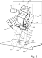
- FIG. 5 here is conceptually depicted a different setup of the components in the interior of the housing 110 of Fig. 1 .
- Fig. 5 also illustrates a portion of the conveyor 108 including the first detection zone 104 and the second detection zone 106.
- the setup depicted in Fig. 5 is similar to that in Fig. 2 . Hence, only relevant differences between Fig. 5 and Fig 2 . will be discussed to avoid undue repetition.
- the received light 122 of the spectroscopy system 120 intersects the line of laser light 130.
- the camera-based sensor arrangement 128 is viewing the second detection zone 106 on the conveyor 108 from above, i.e. in a normal direction with respect to the surface of the conveyor 108 and the laser arrangement 126 is inclined with respect to the surface of the conveyor 108, i.e. not normal to the surface of the conveyor 108.
- the line of laser light 130 impinges on the conveyor 108 in an angled fashion.
- the position of matter 102 in the second detection zone 106 may be compensated for by taking the height or a varying height of the matter 102 into account when determining the position of the matter in the second detection zone 106.
- the processing unit 113 may compensate for the viewing angle of the camera-based sensor arrangement 128 with respect to the second detection zone 106 and hence with respect to the conveyor 108.
- the geometry of the laser arrangement 126 and the camera-based sensor arrangement 128 may be taken into account when determining the position of the matter in the second detection zone 106.
- Fig. 6 here is conceptually depicted a different setup of an apparatus largely corresponding to the apparatus 100 of Fig. 1 . More specifically it is in Fig 6 . conceptually depicted a different setup of the components in the interior of the housing 110 of Fig. 1 . Fig. 5 also illustrates how the conveyor 108 has been replaced by a chute 148.
- the setup depicted in Fig. 6 is to a large extent similar to that in Fig. 2 . Hence, only relevant differences between Fig. 6 and Fig 2 . will be discussed to avoid undue repetition
- the depicted chute 148 is inclined such that the matter 102 is made to freefall of the chute 148 and through the first detection zone 104 and the second detection zone 106.
- the matter may alternatively be slid on the chute 148 through the first detection zone 104 and the second detection zone 106.
- the chute 148 may as an option include a vibration feeder for feeding the matter 102 onto the chute 148.
- the first detection zone 104 and the second detection zone 106 overlap. Hence, matter 102 provided through the first detection zone 104 and the second detection zone 106 will be present in the first detection zone 104 and the second detection zone 106 simultaneously.
- the overlap of the first detection zone 104 and the second detection zone 106 it may be ascertained that measurements made by the spectroscopy system 120 and the laser triangulation system 124 may be correlated to the same piece of matter 102 in the respective detection zones. In other words, wrongful correlation of a particular piece of matter 102 may be counteracted.
- the apparatus 100 may be employed with one or more optical filters 150, 152 as depicted in Fig 6 .
- a fist optical filter 150 is arranged between the light source arrangement 114 and the first detection zone 104. More specifically, the depicted first optical filter 150 of Fig. 6 is located between the scanning element 136 and the first detection zone 104, i.e. in a location where the first set of light beams 116 and the second set of light beams 118 are scanned by the scanning element 136.
- the first optical filter 150 may for this reason have an elongated shape, such as a rectangular shape, along a scan direction.
- the first optical filter 150 may advantageously be arranged at lens or exit window at the light source arrangement 114 or focusing arrangement 134.
- the first optical filter 150 has optical properties that make the filter 150 counteract light originating from the first set of light beams 116 and the second set of light beams 118 from reaching the camera-based sensor arrangement 128.
- the first optical filter 150 may block certain wavelengths of light originating from the first set of light beams 116 and the second set of light beams 118 while allowing other wavelengths to pass. Hence, the first optical filter 150 may block light originating the first set of light beams 116 and the second set of light beams 118 that otherwise would be detected by the camera-based sensor arrangement 128. In practice, the first optical filter 150 may block any light or a major portion of light having a wavelength below 900 nm. Hence, the first optical filter 150 may allow wavelengths in the NIR and IR ranges to pass. The wavelengths in the NIR and IR ranges is relevant for spectroscopy system 120 while not disturbing the camera-based sensor arrangement 128 or only disturbing the camera-based sensor arrangement 128 to a limited extent.
- a second optical filter 152 is arranged between the second detection zone 106 and the camera-based sensor arrangement 128.
- the second optical filter 152 has optical properties that counteract passing of light 122 originating from the first set of light beams 116 and the second set of light beams 118.
- the second optical filter 152 has optical properties that counteract passing of ambient light. Hence, a major portion of ambient light will be blocked by the second optical filter 152.
- the second optical filter 152 has optical properties that allows passage of light originating from the line of laser light 130.
- the second optical filter 152 is typically a bandpass filter having a passband corresponding to the wavelength of the line of laser light 130.
- the arrangement of the second optical filter 152 may counteract undesired light that otherwise would risk disturbing the camera-based sensor arrangement 128 form reaching the same.
- the second optical filter 152 may advantageously have a narrow passband around 622 nm so as to efficiently filter away almost all light not originating from the line of laser light 130.
- the passband of the second optical filter 152 is advantageously tailored to correspond to the wavelength or wavelengths of the line of laser light 130. Relevant bandpass filters for the second optical filter 152 are known in the art per se.
- the apparatus 100 may include a plurality of optical setups each including a light source arrangement 114, a spectroscopy system 120 and a laser triangulation system 124 as described above.
- the optical setups may by arranged side by side over the width or a portion of the width of the conveyor 108 or chute 148. This means in practice that the width of the conveyor 108 or chute 148 may be covered by a plurality of first detection zones 106 and a plurality of second detection zones 108 of the above described type.
- the optical setups may by arranged one after another along the conveyor 108 or chute 148. This means in practice that an extension along the conveyor 108 or chute 148 may be covered by a plurality of first detection zones 106 and a plurality of second detection zones 108 of the above described type.
- the optical setups may by arranged side by side and one after the other. This means in practice that an extension along and across the conveyor 108 or chute 148 may be covered by a plurality of first detection zones 106 and a plurality of second detection zones 108 of the above described type.
- the plurality of first detection zones 106 and second detection zones 108 may for instance partially overlap each other in a direction perpendicular to a flow direction of matter 102 being provided through the first detection zones 106 and second detection zones 108.
- the plurality of first detection zones 106 and second detection zones 108 may for instance partially overlap each other in a direction along a flow direction of matter 102 being provided through the first detection zones 106 and second detection zones 108.
- the plurality of first detection zones 106 and second detection zones 108 may for instance be arranged one after another and at the same time partially overlap each other in a direction perpendicular to a flow direction of matter 102 being provided through the first detection zones 106 and second detection zones 108.
- the plurality of first detection zones 106 and second detection zones 108 may not physically overlap each other but still cover different portions of the width of the conveyor 108 or chute 148.
- the plurality of first detection zones 106 and second detection zones 108 may for instance be arranged side by side and also partially overlap each other in a direction perpendicular to and/or along a flow direction of matter 102 provided through the first detection zones 106 and second detection zones 108.
- the plurality of optical setups is arranged in such a way, that upper surfaces or top surfaces of matter with large or maximum height can be detected across the complete conveyor 108 or chute 148.
- the laser triangulation systems 124 of each optical setup may be adapted such that the plurality of second detection zones 108 do not interfere or only interfere to a limited extent. This may for instance be achieved by adapting the colours of the line of laser light 130 of each optical setup such that each optical setup uses a different colour of the line of laser light 130.
- the first optical filter 150 and the second optical filter of each optical setup may be adapted to suit the light source arrangement 114, the spectroscopy system 120 and the laser triangulation system 124 of each optical setup, thereby further reducing interference between the plurality of second detection zones 108.
- the light source arrangements 114 of each optical setup may be adapted such that the plurality of first detection zones 106 do not interfere or only interfere to a limited extent. This may for instance be achieved by adapting the light source arrangements 114 of each optical setup. The light source arrangements 114 of each optical setup may for this reason be synchronized. This means in practice that the first set of light beams 116 and the second set of light beams 118 of each optical setup may be synchronized so as to counteract interference therebetween. In other words, the first set of light beams 116 and the second set of light beams 118 of each optical setup may not reach the overlapping portions of the plurality of first detection zones 106 simultaneously.
Landscapes
- Physics & Mathematics (AREA)
- Spectroscopy & Molecular Physics (AREA)
- General Physics & Mathematics (AREA)
- Biochemistry (AREA)
- Chemical & Material Sciences (AREA)
- Analytical Chemistry (AREA)
- Life Sciences & Earth Sciences (AREA)
- General Health & Medical Sciences (AREA)
- Health & Medical Sciences (AREA)
- Immunology (AREA)
- Pathology (AREA)
- Optics & Photonics (AREA)
- Investigating Or Analysing Materials By Optical Means (AREA)
- Sorting Of Articles (AREA)
Claims (17)
- Einrichtung (100) zum Detektieren einer Substanz (102), wobei die Einrichtung (100) Folgendes umfasst:eine Lichtquellenanordnung (114), die zum Emittieren eines ersten Satzes von Lichtstrahlen (116) und eines zweiten Satzes von Lichtstrahlen (118) zu einer ersten Detektionszone (104) hin eingerichtet ist, durch die die Substanz (102) bereitgestellt wird,ein Spektroskopiesystem (120) einschließlich eines Spektrometers, wobei das Spektroskopiesystem (120) zum Empfangen und Analysieren von Licht (122) eingerichtet ist, das durch eine Substanz (102) in der ersten Detektionszone (104) reflektiert und/oder gestreut wird, wobei das empfangene Licht (122) des Spektroskopiesystems (120) von dem ersten (116) und zweiten Satz von Lichtstrahlen (118) stammt, und ein Lasertriangulationssystem (124), das Folgendes beinhaltet:eine Laseranordnung (126), die zum Emittieren einer Linie von Laserlicht (130) zu einer zweiten Detektionszone (106) hin eingerichtet ist, durch die die Substanz (102) bereitgestellt wird, undeine kamerabasierte Sensoranordnung (128), die zum Empfangen und Analysieren von Licht (132) konfiguriert ist, das durch eine Substanz (102) in der zweiten Detektionszone (106) reflektiert und/oder gestreut wird, wobei das empfangene Licht (132) der kamerabasierten Sensoranordnung (128) von der Linie von Laserlicht (130) stammt,wobei die Einrichtung derart konfiguriert ist, dass das empfangene Licht (122) des Spektroskopiesystems (120) vollständig das empfangene Licht (132) der kamerabasierten Sensoranordnung (128) und/oder die Linie von Laserlicht (130) schneidet, dadurch gekennzeichnet, dass die Einrichtung derart konfiguriert ist, dass die Substanz (102) zuerst durch die erste Detektionszone (104) oder die zweite Detektionszone (106) und anschließend durch die andere der ersten Detektionszone (104) und der zweiten Detektionszone (106) bereitgestellt wird.
- Einrichtung (100) nach Anspruch 1, wobei die Einrichtung (100) ferner eine Fokussierungsanordnung (134) umfasst,wobei die Fokussierungsanordnung (134) zum Lenken und Fokussieren des ersten Satzes von Lichtstrahlen (116) und des zweiten Satzes von Lichtstrahlen (118) auf ein Scanelement (136) eingerichtet ist,wobei das Scanelement (136) zum Umlenken des ersten und zweiten Satzes von Lichtstrahlen (116, 118) zu der ersten Detektionszone (104) hin konfiguriert ist, wodurch der erste und zweite Satz von Lichtstrahlen (116, 118) bei der ersten Detektionszone (104) konvergieren.
- Einrichtung (100) nach Anspruch 1 oder 2, wobei die Lichtquellenanordnung (114) eine erste Lichtquelle (138), die zum Emittieren des ersten Satzes von Lichtstrahlen (116) eingerichtet ist, und eine zweite Lichtquelle (140) beinhaltet, die zum Emittieren des zweiten Satzes von Lichtstrahlen (118) eingerichtet ist.
- Einrichtung (100) nach Anspruch 2 oder 3, wobei die Fokussierungsanordnung (134) ein erstes Fokussierungselement (142), das zum Lenken und Fokussieren des ersten Satzes von Lichtstrahlen (116) auf das Scanelement (136) eingerichtet ist, und ein zweites Fokussierungselement (144) beinhaltet, das zum Lenken und Fokussieren des zweiten Satzes von Lichtstrahlen (118) auf das Scanelement (136) eingerichtet ist.
- Einrichtung (100) nach Anspruch 1 oder 2, wobei die Lichtquellenanordnung (134) eine einzige Lichtquelle (146) beinhaltet, die zum Emittieren des ersten Satzes von Lichtstrahlen (116) und des zweiten Satzes von Lichtstrahlen (118) eingerichtet ist.
- Einrichtung (100) nach Anspruch 5, wenn abhängig von Anspruch 2, wobei die Fokussierungsanordnung (134) ein erstes Fokussierungselement (142), das zum Lenken und Fokussieren des ersten Satzes von Lichtstrahlen (116) auf das Scanelement (136) eingerichtet ist, und ein zweites Fokussierungselement (144) beinhaltet, das zum Lenken und Fokussieren des zweiten Satzes von Lichtstrahlen (118) auf das Scanelement (136) eingerichtet ist.
- Einrichtung (100) nach einem der vorhergehenden Ansprüche, wobei das Spektroskopiesystem (120) ein erstes Spektrometersystem (120), das zum Analysieren von Licht eines ersten Wellenlängenintervalls eingerichtet ist, und ein zweites Spektrometersystem (120) beinhaltet, das zum Analysieren von Licht eines zweiten Wellenlängenintervalls eingerichtet ist.
- Einrichtung (100) nach einem der vorhergehenden Ansprüche, wobei das Spektroskopiesystem (120) ein Rasterspektroskopiesystem (120) ist.
- Einrichtung (100) nach einem der vorhergehenden Ansprüche, wobei die erste Detektionszone (104) und die zweite Detektionszone (106) überlappen.
- Einrichtung (100) nach einem der vorhergehenden Ansprüche, wobei die Einrichtung (100) ferner ein erstes optisches Filter (150) beinhaltet, das zwischen der Lichtquellenanordnung (114) und der ersten Detektionszone (104) angeordnet ist, wobei das erste optische Filter (150) dem entgegenwirkt, dass Licht, das von dem ersten Satz von Lichtstrahlen (116) und dem zweiten Satz von Lichtstrahlen (118) stammt, die kamerabasierte Sensoranordnung (128) erreicht.
- Einrichtung (100) nach einem der vorhergehenden Ansprüche, wobei die Einrichtung (100) ferner ein zweites optisches Filter (152) beinhaltet, das zwischen der zweiten Detektionszone (106) und der kamerabasierten Sensoranordnung (128) angeordnet ist, wobei das zweite optische Filter (152) einem Durchgang von Licht (122) entgegenwirkt, das von dem ersten Satz von Lichtstrahlen (116), dem zweiten Satz von Lichtstrahlen (118) und Umgebungslicht stammt, während ein Durchgang von Licht ermöglicht wird, das von der Linie von Laserlicht (130) stammt.
- Einrichtung (100) nach einem der vorhergehenden Ansprüche, wobei die Einrichtung (100) ferner eine Verarbeitungseinheit (113) umfasst, die mit dem Spektroskopiesystem (120) und der kamerabasierten Sensoranordnung (128) gekoppelt ist,wobei die Verarbeitungseinheit (113) zum Bestimmen eines ersten Eigenschaftssatzes in Bezug auf eine Substanz (102) in der ersten Detektionszone (106) basierend auf einem ausgegebenen Signal (S1) des Spektroskopiesystems (120) konfiguriert ist, undwobei die Verarbeitungseinheit (113) zum Bestimmen eines zweiten Eigenschaftssatzes in Bezug auf eine Substanz (102) in der zweiten Detektionszone (108) basierend auf einem ausgegebenen Signal (S2) der kamerabasierten Sensoranordnung (128) konfiguriert ist.
- Einrichtung (100) nach Anspruch 12, wobei der erste Eigenschaftssatz wenigstens eines von einer spektralen Antwort der Substanz (102), einem Materialtyp der Substanz (102), einer Farbe der Substanz (102), einer Fluoreszenz der Substanz (102), einem Reifegrad der Substanz (102), einem Trockensubstanzanteil einer Substanz (102), einem Wasseranteil der Substanz (102), einem Fettanteil der Substanz (102), einem Ölanteil der Substanz (102), einem Brennwert der Substanz (102), einer Anwesenheit von Knochen oder Gräten der Substanz (102), einer Anwesenheit von Schädlingen der Substanz (102), einem Mineraltyp der Substanz (102), einem Erztyp der Substanz (102), einem Defektniveau der Substanz (102), einer Detektion von gefährlichen biologischen Materialien der Substanz (102), einer Anwesenheit einer Substanz (102), einem Nichtvorhandensein einer Substanz (102), einer Detektion von Mehrschichtmaterialien der Substanz (102), einer Detektion von Fluoreszenzmarkern der Substanz (102), einer Güteklasse der Substanz (102), einer physischen Struktur der Oberfläche der Substanz (102) und einer molekularen Struktur der Substanz (102) angibt.
- Einrichtung (100) nach Anspruch 12 oder 13, wobei der zweite Eigenschaftssatz wenigstens eines von einer Höhe der Substanz (102), einem Höhenprofil der Substanz (102), einer 3D-Karte der Substanz (102), einem Intensitätsprofil von reflektiertem und/oder gestreutem Licht (132), einem Volumenzentrum der Substanz (102), einem geschätzten Schwerpunkt der Substanz (102), einem geschätzten Gewicht der Substanz (102), einem geschätzten Material der Substanz (102), einer Anwesenheit einer Substanz (102), einem Nichtvorhandensein einer Substanz (102), einer Detektion von isotroper und anisotroper Lichtstreuung der Substanz (102), einer Struktur und Qualität von Holz, einer Oberflächenrauigkeit und Textur der Substanz (102) und einer Indikation der Anwesenheit von Fluiden in der Substanz (102) angibt.
- Einrichtung (100) nach einem der Ansprüche 12-14, wobei die Verarbeitungseinheit (113) ferner zu Folgendem konfiguriert ist: Empfangen einer Eingabe, die einen Betrachtungswinkel der kamerabasierten Sensoranordnung (128) mit Bezug auf die zweite Detektionszone (106) angibt, und
Kompensieren des Betrachtungswinkels der kamerabasierten Sensoranordnung (128), wenn der zweite Eigenschaftssatz bestimmt wird. - Einrichtung nach einem der Ansprüche 12-15, wobei die Einrichtung (100) ferner eine Ausstoßanordnung (112) umfasst, die mit der Verarbeitungseinheit (113) gekoppelt ist,
wobei die Ausstoßanordnung (112) zum Ausstoßen und Sortieren einer Substanz (102) in mehrere Teile als Reaktion auf das Empfangen eines Signals von der Verarbeitungseinheit (113) basierend auf dem bestimmten ersten Eigenschaftssatz und/oder dem bestimmten zweiten Eigenschaftssatz eingerichtet ist, wobei die Ausstoßanordnung (112) zum Ausstoßen und Sortieren der Substanz (102) mittels wenigstens eines von einem Druckluftstrahl, einem Druckwasserstrahl, einem mechanischen Finger, einem Streifen von Druckluftstrahlen, einem Streifen von Druckwasserstrahlen, einem Streifen von mechanischen Fingern, einem Roboterarm und einem mechanischen Ablenkelement eingerichtet ist. - Einrichtung (100) nach einem der vorhergehenden Ansprüche, wobei die Einrichtung (100) ferner Folgendes umfasst:ein Transportband (108) zum Transportieren einer Substanz durch die erste Detektionszone (104) und die zweite Detektionszone (106), odereine Rutsche (148), optional einschließlich eines Vibrationsförderers, um die Substanz durch die erste Detektionszone und/oder die zweite Detektionszone rutschen oder fallen zu lassen.
Applications Claiming Priority (2)
| Application Number | Priority Date | Filing Date | Title |
|---|---|---|---|
| EP20178662 | 2020-06-08 | ||
| PCT/EP2021/061647 WO2021249698A1 (en) | 2020-06-08 | 2021-05-04 | Apparatus for detecting matter |
Publications (2)
| Publication Number | Publication Date |
|---|---|
| EP4162256A1 EP4162256A1 (de) | 2023-04-12 |
| EP4162256B1 true EP4162256B1 (de) | 2024-10-16 |
Family
ID=71069719
Family Applications (1)
| Application Number | Title | Priority Date | Filing Date |
|---|---|---|---|
| EP21723244.6A Active EP4162256B1 (de) | 2020-06-08 | 2021-05-04 | Vorrichtung zum nachweis von stoffen |
Country Status (12)
| Country | Link |
|---|---|
| US (1) | US12480871B2 (de) |
| EP (1) | EP4162256B1 (de) |
| JP (1) | JP2023529580A (de) |
| KR (1) | KR20230021119A (de) |
| CN (1) | CN115769061A (de) |
| AU (1) | AU2021286772A1 (de) |
| BR (1) | BR112022024482A2 (de) |
| CA (1) | CA3181055A1 (de) |
| ES (1) | ES3004941T3 (de) |
| PL (1) | PL4162256T3 (de) |
| TW (1) | TW202146838A (de) |
| WO (1) | WO2021249698A1 (de) |
Families Citing this family (10)
| Publication number | Priority date | Publication date | Assignee | Title |
|---|---|---|---|---|
| US11878327B2 (en) | 2019-03-13 | 2024-01-23 | Digimarc Corporation | Methods and arrangements for sorting items, useful in recycling |
| WO2023199102A1 (en) | 2022-04-14 | 2023-10-19 | Tomra Sorting Gmbh | Scanning of objects |
| EP4508418A1 (de) | 2022-04-14 | 2025-02-19 | Tomra Food (Belgium) N.V. | Abtasten von objekten |
| EP4332557B1 (de) * | 2022-08-31 | 2024-06-26 | Unity Semiconductor | System zur optischen inspektion eines substrats unter verwendung derselben oder verschiedener wellenlängen |
| EP4429831B1 (de) * | 2022-10-24 | 2025-12-24 | Wacker Chemie AG | Verfahren und vorrichtung zum sortieren von siliciumbruchstücken |
| CN115815150A (zh) * | 2022-11-09 | 2023-03-21 | 安徽中科光电色选机械有限公司 | 一种基于三维检测和光谱检测的高速分选装置 |
| KR20250174622A (ko) | 2023-04-04 | 2025-12-12 | 톰라 소팅 게엠베하 | Rgb 카메라 스캔 조명 |
| WO2025016952A1 (en) | 2023-07-14 | 2025-01-23 | Basf Se | Method and system for classifying polyurethane objects from a waste stream |
| WO2025160073A1 (en) * | 2024-01-24 | 2025-07-31 | Huron Valley Steel Corporation | Scrap sorting system |
| KR102732204B1 (ko) * | 2024-02-28 | 2024-11-20 | (주)우림아이씨티 | 재활용 폐기물 선별 제어 장치 및 그 방법 |
Family Cites Families (15)
| Publication number | Priority date | Publication date | Assignee | Title |
|---|---|---|---|---|
| DE19650705A1 (de) | 1996-12-08 | 1998-06-10 | Robert Prof Dr Ing Massen | Multisensorielle Kamera mit kompakter Sensoranordnung |
| US6369882B1 (en) * | 1999-04-29 | 2002-04-09 | Advanced Sorting Technologies Llc | System and method for sensing white paper |
| BE1012795A3 (nl) * | 1999-07-23 | 2001-03-06 | Barco Elbicon N V | Gebruik van optische golfgeleidertechnologie in een sorteerinrichting. |
| BE1015418A3 (de) * | 2003-03-18 | 2005-03-01 | Pulsarr Ind Res B V | |
| JP2010117263A (ja) * | 2008-11-13 | 2010-05-27 | Sumitomo Electric Ind Ltd | 異物検査装置 |
| CN101592598B (zh) * | 2009-07-10 | 2010-09-29 | 杭州电子科技大学 | 一种基于近场光学行波吸收的痕量物质分析装置 |
| EP2462429A1 (de) * | 2009-08-05 | 2012-06-13 | Corning Inc. | Etikettunabhängiges optisches lesesystem und verfahren mit optischer abtastung |
| DE102010030908B4 (de) * | 2010-07-02 | 2014-10-16 | Strube Gmbh & Co. Kg | Verfahren zur Klassifizierung in Saatgutpartien enthaltener Objekte, Sortierverfahren und zugehörige Vorrichtungen |
| WO2015063299A1 (en) | 2013-11-01 | 2015-05-07 | Tomra Sorting Nv | Method and apparatus for detecting matter |
| CN105874321B (zh) * | 2013-11-04 | 2019-06-28 | 陶朗分选股份有限公司 | 检查设备 |
| CN107851176A (zh) * | 2015-02-06 | 2018-03-27 | 阿克伦大学 | 光学成像系统及其方法 |
| CN104819743B (zh) * | 2015-04-30 | 2017-05-10 | 杭州电子科技大学 | 一种基于激光感知的多参数检测方法 |
| CN105628679B (zh) * | 2016-03-23 | 2018-06-29 | 中国科学院上海技术物理研究所 | 基于红外拉曼紫外荧光超连续谱的血液鉴别仪 |
| DK3367054T3 (da) | 2017-02-28 | 2020-07-13 | Phenospex B V | System til optisk registrering af objekter |
| US10732354B2 (en) * | 2018-06-06 | 2020-08-04 | Boston Medical Center Corporation | Systems and methods for fiber-based visible and near infrared optical coherence tomography |
-
2021
- 2021-05-04 WO PCT/EP2021/061647 patent/WO2021249698A1/en not_active Ceased
- 2021-05-04 AU AU2021286772A patent/AU2021286772A1/en active Pending
- 2021-05-04 US US18/000,549 patent/US12480871B2/en active Active
- 2021-05-04 JP JP2022572265A patent/JP2023529580A/ja active Pending
- 2021-05-04 CA CA3181055A patent/CA3181055A1/en active Pending
- 2021-05-04 CN CN202180039035.4A patent/CN115769061A/zh active Pending
- 2021-05-04 KR KR1020237000604A patent/KR20230021119A/ko active Pending
- 2021-05-04 PL PL21723244.6T patent/PL4162256T3/pl unknown
- 2021-05-04 ES ES21723244T patent/ES3004941T3/es active Active
- 2021-05-04 BR BR112022024482A patent/BR112022024482A2/pt unknown
- 2021-05-04 EP EP21723244.6A patent/EP4162256B1/de active Active
- 2021-05-12 TW TW110117154A patent/TW202146838A/zh unknown
Also Published As
| Publication number | Publication date |
|---|---|
| CA3181055A1 (en) | 2021-12-16 |
| US12480871B2 (en) | 2025-11-25 |
| PL4162256T3 (pl) | 2025-03-03 |
| TW202146838A (zh) | 2021-12-16 |
| ES3004941T3 (en) | 2025-03-13 |
| AU2021286772A1 (en) | 2022-12-08 |
| CN115769061A (zh) | 2023-03-07 |
| EP4162256A1 (de) | 2023-04-12 |
| BR112022024482A2 (pt) | 2022-12-27 |
| JP2023529580A (ja) | 2023-07-11 |
| US20230213443A1 (en) | 2023-07-06 |
| WO2021249698A1 (en) | 2021-12-16 |
| KR20230021119A (ko) | 2023-02-13 |
Similar Documents
| Publication | Publication Date | Title |
|---|---|---|
| EP4162256B1 (de) | Vorrichtung zum nachweis von stoffen | |
| JP6792101B2 (ja) | 分類の方法および装置 | |
| US10189055B2 (en) | Color based optical grading system with multi reflectance and multi-angle views | |
| EP4445119B1 (de) | Materialidentifizierungsvorrichtung und -verfahren | |
| EP2726221B1 (de) | Inspektionseinrichtung mit wechselnder seitenbeleuchtung | |
| CA2310838A1 (en) | Method and device for identifying and sorting objects conveyed on a belt | |
| US20250018433A1 (en) | Apparatus for illuminating matter | |
| RU2403100C2 (ru) | Устройство для сортировки зерна по цвету | |
| WO2025021562A1 (en) | Inspection arrangement and method for analysing items | |
| CN120936866A (zh) | Rgb相机扫描照明 |
Legal Events
| Date | Code | Title | Description |
|---|---|---|---|
| STAA | Information on the status of an ep patent application or granted ep patent |
Free format text: STATUS: UNKNOWN |
|
| STAA | Information on the status of an ep patent application or granted ep patent |
Free format text: STATUS: THE INTERNATIONAL PUBLICATION HAS BEEN MADE |
|
| PUAI | Public reference made under article 153(3) epc to a published international application that has entered the european phase |
Free format text: ORIGINAL CODE: 0009012 |
|
| STAA | Information on the status of an ep patent application or granted ep patent |
Free format text: STATUS: REQUEST FOR EXAMINATION WAS MADE |
|
| 17P | Request for examination filed |
Effective date: 20221129 |
|
| AK | Designated contracting states |
Kind code of ref document: A1 Designated state(s): AL AT BE BG CH CY CZ DE DK EE ES FI FR GB GR HR HU IE IS IT LI LT LU LV MC MK MT NL NO PL PT RO RS SE SI SK SM TR |
|
| DAV | Request for validation of the european patent (deleted) | ||
| DAX | Request for extension of the european patent (deleted) | ||
| RIC1 | Information provided on ipc code assigned before grant |
Ipc: G01N 21/84 20060101ALN20240404BHEP Ipc: B07C 5/342 20060101ALI20240404BHEP Ipc: G01N 21/3563 20140101ALI20240404BHEP Ipc: G01N 21/85 20060101ALI20240404BHEP Ipc: G01N 21/31 20060101AFI20240404BHEP |
|
| GRAP | Despatch of communication of intention to grant a patent |
Free format text: ORIGINAL CODE: EPIDOSNIGR1 |
|
| RIC1 | Information provided on ipc code assigned before grant |
Ipc: G01N 21/84 20060101ALN20240411BHEP Ipc: B07C 5/342 20060101ALI20240411BHEP Ipc: G01N 21/3563 20140101ALI20240411BHEP Ipc: G01N 21/85 20060101ALI20240411BHEP Ipc: G01N 21/31 20060101AFI20240411BHEP |
|
| STAA | Information on the status of an ep patent application or granted ep patent |
Free format text: STATUS: GRANT OF PATENT IS INTENDED |
|
| INTG | Intention to grant announced |
Effective date: 20240516 |
|
| GRAS | Grant fee paid |
Free format text: ORIGINAL CODE: EPIDOSNIGR3 |
|
| GRAA | (expected) grant |
Free format text: ORIGINAL CODE: 0009210 |
|
| STAA | Information on the status of an ep patent application or granted ep patent |
Free format text: STATUS: THE PATENT HAS BEEN GRANTED |
|
| AK | Designated contracting states |
Kind code of ref document: B1 Designated state(s): AL AT BE BG CH CY CZ DE DK EE ES FI FR GB GR HR HU IE IS IT LI LT LU LV MC MK MT NL NO PL PT RO RS SE SI SK SM TR |
|
| P01 | Opt-out of the competence of the unified patent court (upc) registered |
Free format text: CASE NUMBER: APP_50437/2024 Effective date: 20240906 |
|
| REG | Reference to a national code |
Ref country code: GB Ref legal event code: FG4D |
|
| REG | Reference to a national code |
Ref country code: CH Ref legal event code: EP Ref country code: DE Ref legal event code: R096 Ref document number: 602021020360 Country of ref document: DE |
|
| REG | Reference to a national code |
Ref country code: IE Ref legal event code: FG4D Ref country code: NL Ref legal event code: FP |
|
| REG | Reference to a national code |
Ref country code: SK Ref legal event code: T3 Ref document number: E 45319 Country of ref document: SK |
|
| REG | Reference to a national code |
Ref country code: SE Ref legal event code: TRGR |
|
| REG | Reference to a national code |
Ref country code: LT Ref legal event code: MG9D |
|
| REG | Reference to a national code |
Ref country code: ES Ref legal event code: FG2A Ref document number: 3004941 Country of ref document: ES Kind code of ref document: T3 Effective date: 20250313 |
|
| PG25 | Lapsed in a contracting state [announced via postgrant information from national office to epo] |
Ref country code: PT Free format text: LAPSE BECAUSE OF FAILURE TO SUBMIT A TRANSLATION OF THE DESCRIPTION OR TO PAY THE FEE WITHIN THE PRESCRIBED TIME-LIMIT Effective date: 20250217 Ref country code: HR Free format text: LAPSE BECAUSE OF FAILURE TO SUBMIT A TRANSLATION OF THE DESCRIPTION OR TO PAY THE FEE WITHIN THE PRESCRIBED TIME-LIMIT Effective date: 20241016 Ref country code: IS Free format text: LAPSE BECAUSE OF FAILURE TO SUBMIT A TRANSLATION OF THE DESCRIPTION OR TO PAY THE FEE WITHIN THE PRESCRIBED TIME-LIMIT Effective date: 20250216 |
|
| PG25 | Lapsed in a contracting state [announced via postgrant information from national office to epo] |
Ref country code: FI Free format text: LAPSE BECAUSE OF FAILURE TO SUBMIT A TRANSLATION OF THE DESCRIPTION OR TO PAY THE FEE WITHIN THE PRESCRIBED TIME-LIMIT Effective date: 20241016 |
|
| PG25 | Lapsed in a contracting state [announced via postgrant information from national office to epo] |
Ref country code: BG Free format text: LAPSE BECAUSE OF FAILURE TO SUBMIT A TRANSLATION OF THE DESCRIPTION OR TO PAY THE FEE WITHIN THE PRESCRIBED TIME-LIMIT Effective date: 20241016 |
|
| PG25 | Lapsed in a contracting state [announced via postgrant information from national office to epo] |
Ref country code: NO Free format text: LAPSE BECAUSE OF FAILURE TO SUBMIT A TRANSLATION OF THE DESCRIPTION OR TO PAY THE FEE WITHIN THE PRESCRIBED TIME-LIMIT Effective date: 20250116 |
|
| PG25 | Lapsed in a contracting state [announced via postgrant information from national office to epo] |
Ref country code: LV Free format text: LAPSE BECAUSE OF FAILURE TO SUBMIT A TRANSLATION OF THE DESCRIPTION OR TO PAY THE FEE WITHIN THE PRESCRIBED TIME-LIMIT Effective date: 20241016 Ref country code: GR Free format text: LAPSE BECAUSE OF FAILURE TO SUBMIT A TRANSLATION OF THE DESCRIPTION OR TO PAY THE FEE WITHIN THE PRESCRIBED TIME-LIMIT Effective date: 20250117 |
|
| PG25 | Lapsed in a contracting state [announced via postgrant information from national office to epo] |
Ref country code: RS Free format text: LAPSE BECAUSE OF FAILURE TO SUBMIT A TRANSLATION OF THE DESCRIPTION OR TO PAY THE FEE WITHIN THE PRESCRIBED TIME-LIMIT Effective date: 20250116 |
|
| PGFP | Annual fee paid to national office [announced via postgrant information from national office to epo] |
Ref country code: NL Payment date: 20250409 Year of fee payment: 5 |
|
| PG25 | Lapsed in a contracting state [announced via postgrant information from national office to epo] |
Ref country code: SM Free format text: LAPSE BECAUSE OF FAILURE TO SUBMIT A TRANSLATION OF THE DESCRIPTION OR TO PAY THE FEE WITHIN THE PRESCRIBED TIME-LIMIT Effective date: 20241016 |
|
| PGFP | Annual fee paid to national office [announced via postgrant information from national office to epo] |
Ref country code: PL Payment date: 20250414 Year of fee payment: 5 Ref country code: DE Payment date: 20250402 Year of fee payment: 5 |
|
| PG25 | Lapsed in a contracting state [announced via postgrant information from national office to epo] |
Ref country code: DK Free format text: LAPSE BECAUSE OF FAILURE TO SUBMIT A TRANSLATION OF THE DESCRIPTION OR TO PAY THE FEE WITHIN THE PRESCRIBED TIME-LIMIT Effective date: 20241016 |
|
| PGFP | Annual fee paid to national office [announced via postgrant information from national office to epo] |
Ref country code: GB Payment date: 20250401 Year of fee payment: 5 Ref country code: ES Payment date: 20250605 Year of fee payment: 5 |
|
| PGFP | Annual fee paid to national office [announced via postgrant information from national office to epo] |
Ref country code: IT Payment date: 20250422 Year of fee payment: 5 |
|
| REG | Reference to a national code |
Ref country code: DE Ref legal event code: R097 Ref document number: 602021020360 Country of ref document: DE |
|
| PG25 | Lapsed in a contracting state [announced via postgrant information from national office to epo] |
Ref country code: EE Free format text: LAPSE BECAUSE OF FAILURE TO SUBMIT A TRANSLATION OF THE DESCRIPTION OR TO PAY THE FEE WITHIN THE PRESCRIBED TIME-LIMIT Effective date: 20241016 |
|
| PGFP | Annual fee paid to national office [announced via postgrant information from national office to epo] |
Ref country code: FR Payment date: 20250401 Year of fee payment: 5 |
|
| PG25 | Lapsed in a contracting state [announced via postgrant information from national office to epo] |
Ref country code: RO Free format text: LAPSE BECAUSE OF FAILURE TO SUBMIT A TRANSLATION OF THE DESCRIPTION OR TO PAY THE FEE WITHIN THE PRESCRIBED TIME-LIMIT Effective date: 20241016 |
|
| PGFP | Annual fee paid to national office [announced via postgrant information from national office to epo] |
Ref country code: AT Payment date: 20250721 Year of fee payment: 5 |
|
| PGFP | Annual fee paid to national office [announced via postgrant information from national office to epo] |
Ref country code: TR Payment date: 20250425 Year of fee payment: 5 Ref country code: SK Payment date: 20250416 Year of fee payment: 5 |
|
| PG25 | Lapsed in a contracting state [announced via postgrant information from national office to epo] |
Ref country code: CZ Free format text: LAPSE BECAUSE OF FAILURE TO SUBMIT A TRANSLATION OF THE DESCRIPTION OR TO PAY THE FEE WITHIN THE PRESCRIBED TIME-LIMIT Effective date: 20241016 |
|
| PGFP | Annual fee paid to national office [announced via postgrant information from national office to epo] |
Ref country code: SE Payment date: 20250411 Year of fee payment: 5 |
|
| PLBE | No opposition filed within time limit |
Free format text: ORIGINAL CODE: 0009261 |
|
| STAA | Information on the status of an ep patent application or granted ep patent |
Free format text: STATUS: NO OPPOSITION FILED WITHIN TIME LIMIT |
|
| 26N | No opposition filed |
Effective date: 20250717 |
|
| REG | Reference to a national code |
Ref country code: CH Ref legal event code: H13 Free format text: ST27 STATUS EVENT CODE: U-0-0-H10-H13 (AS PROVIDED BY THE NATIONAL OFFICE) Effective date: 20251223 |
|
| PG25 | Lapsed in a contracting state [announced via postgrant information from national office to epo] |
Ref country code: LU Free format text: LAPSE BECAUSE OF NON-PAYMENT OF DUE FEES Effective date: 20250504 |
|
| PG25 | Lapsed in a contracting state [announced via postgrant information from national office to epo] |
Ref country code: CH Free format text: LAPSE BECAUSE OF NON-PAYMENT OF DUE FEES Effective date: 20250531 |
|
| PG25 | Lapsed in a contracting state [announced via postgrant information from national office to epo] |
Ref country code: MC Free format text: LAPSE BECAUSE OF FAILURE TO SUBMIT A TRANSLATION OF THE DESCRIPTION OR TO PAY THE FEE WITHIN THE PRESCRIBED TIME-LIMIT Effective date: 20241016 |