EP4161037B1 - Electronic apparatus - Google Patents
Electronic apparatus Download PDFInfo
- Publication number
- EP4161037B1 EP4161037B1 EP21812463.4A EP21812463A EP4161037B1 EP 4161037 B1 EP4161037 B1 EP 4161037B1 EP 21812463 A EP21812463 A EP 21812463A EP 4161037 B1 EP4161037 B1 EP 4161037B1
- Authority
- EP
- European Patent Office
- Prior art keywords
- cam
- location
- housing
- functional device
- electronic device
- Prior art date
- Legal status (The legal status is an assumption and is not a legal conclusion. Google has not performed a legal analysis and makes no representation as to the accuracy of the status listed.)
- Active
Links
Images



Classifications
-
- G—PHYSICS
- G06—COMPUTING OR CALCULATING; COUNTING
- G06F—ELECTRIC DIGITAL DATA PROCESSING
- G06F3/00—Input arrangements for transferring data to be processed into a form capable of being handled by the computer; Output arrangements for transferring data from processing unit to output unit, e.g. interface arrangements
- G06F3/01—Input arrangements or combined input and output arrangements for interaction between user and computer
- G06F3/016—Input arrangements with force or tactile feedback as computer generated output to the user
-
- H—ELECTRICITY
- H04—ELECTRIC COMMUNICATION TECHNIQUE
- H04M—TELEPHONIC COMMUNICATION
- H04M1/00—Substation equipment, e.g. for use by subscribers
- H04M1/02—Constructional features of telephone sets
- H04M1/0202—Portable telephone sets, e.g. cordless phones, mobile phones or bar type handsets
- H04M1/026—Details of the structure or mounting of specific components
-
- H—ELECTRICITY
- H10—SEMICONDUCTOR DEVICES; ELECTRIC SOLID-STATE DEVICES NOT OTHERWISE PROVIDED FOR
- H10N—ELECTRIC SOLID-STATE DEVICES NOT OTHERWISE PROVIDED FOR
- H10N30/00—Piezoelectric or electrostrictive devices
- H10N30/101—Piezoelectric or electrostrictive devices with electrical and mechanical input and output, e.g. having combined actuator and sensor parts
-
- G—PHYSICS
- G06—COMPUTING OR CALCULATING; COUNTING
- G06F—ELECTRIC DIGITAL DATA PROCESSING
- G06F1/00—Details not covered by groups G06F3/00 - G06F13/00 and G06F21/00
- G06F1/16—Constructional details or arrangements
- G06F1/1601—Constructional details related to the housing of computer displays, e.g. of CRT monitors, of flat displays
-
- G—PHYSICS
- G06—COMPUTING OR CALCULATING; COUNTING
- G06F—ELECTRIC DIGITAL DATA PROCESSING
- G06F1/00—Details not covered by groups G06F3/00 - G06F13/00 and G06F21/00
- G06F1/16—Constructional details or arrangements
- G06F1/1613—Constructional details or arrangements for portable computers
- G06F1/1626—Constructional details or arrangements for portable computers with a single-body enclosure integrating a flat display, e.g. Personal Digital Assistants [PDAs]
-
- H—ELECTRICITY
- H02—GENERATION; CONVERSION OR DISTRIBUTION OF ELECTRIC POWER
- H02N—ELECTRIC MACHINES NOT OTHERWISE PROVIDED FOR
- H02N2/00—Electric machines in general using piezoelectric effect, electrostriction or magnetostriction
- H02N2/10—Electric machines in general using piezoelectric effect, electrostriction or magnetostriction producing rotary motion, e.g. rotary motors
- H02N2/103—Electric machines in general using piezoelectric effect, electrostriction or magnetostriction producing rotary motion, e.g. rotary motors by pressing one or more vibrators against the rotor
-
- H—ELECTRICITY
- H04—ELECTRIC COMMUNICATION TECHNIQUE
- H04M—TELEPHONIC COMMUNICATION
- H04M1/00—Substation equipment, e.g. for use by subscribers
- H04M1/02—Constructional features of telephone sets
- H04M1/0202—Portable telephone sets, e.g. cordless phones, mobile phones or bar type handsets
- H04M1/0206—Portable telephones comprising a plurality of mechanically joined movable body parts, e.g. hinged housings
- H04M1/0208—Portable telephones comprising a plurality of mechanically joined movable body parts, e.g. hinged housings characterized by the relative motions of the body parts
- H04M1/0235—Slidable or telescopic telephones, i.e. with a relative translation movement of the body parts; Telephones using a combination of translation and other relative motions of the body parts
- H04M1/0237—Sliding mechanism with one degree of freedom
-
- H—ELECTRICITY
- H04—ELECTRIC COMMUNICATION TECHNIQUE
- H04M—TELEPHONIC COMMUNICATION
- H04M1/00—Substation equipment, e.g. for use by subscribers
- H04M1/02—Constructional features of telephone sets
- H04M1/0202—Portable telephone sets, e.g. cordless phones, mobile phones or bar type handsets
- H04M1/0249—Details of the mechanical connection between the housing parts or relating to the method of assembly
-
- G—PHYSICS
- G06—COMPUTING OR CALCULATING; COUNTING
- G06F—ELECTRIC DIGITAL DATA PROCESSING
- G06F1/00—Details not covered by groups G06F3/00 - G06F13/00 and G06F21/00
- G06F1/16—Constructional details or arrangements
- G06F1/1613—Constructional details or arrangements for portable computers
- G06F1/163—Wearable computers, e.g. on a belt
-
- H—ELECTRICITY
- H04—ELECTRIC COMMUNICATION TECHNIQUE
- H04M—TELEPHONIC COMMUNICATION
- H04M1/00—Substation equipment, e.g. for use by subscribers
- H04M1/02—Constructional features of telephone sets
- H04M1/0202—Portable telephone sets, e.g. cordless phones, mobile phones or bar type handsets
- H04M1/026—Details of the structure or mounting of specific components
- H04M1/0264—Details of the structure or mounting of specific components for a camera module assembly
-
- H—ELECTRICITY
- H04—ELECTRIC COMMUNICATION TECHNIQUE
- H04N—PICTORIAL COMMUNICATION, e.g. TELEVISION
- H04N23/00—Cameras or camera modules comprising electronic image sensors; Control thereof
- H04N23/57—Mechanical or electrical details of cameras or camera modules specially adapted for being embedded in other devices
Definitions
- the present application relates to the technical field of communication devices, and in particular, to an electronic device.
- Technological innovations enable the types of the electronic devices to be gradually increased, and the development process of a wearable smart device represented by a smart watch is extremely fast.
- An acoustic device is disposed on the smart watch, so that the smart watch has a call function, and some smart watches are further equipped with cameras, so that the smart watches have a video call function.
- a functional device such as the camera, is generally fixed beside a display screen, however, this arrangement causes that a screen-to-body ratio of the smart watch is relatively small, and if the smart watch collides, it extremely causes damage to the functional device.
- CN210578670U relates to a camera telescoping mechanism and a mobile terminal
- the camera telescoping mechanism is used for installing a camera module and driving the camera module to perform telescoping motion
- the camera telescoping mechanism comprises an energy storage driving unit which is used for being connected to the camera module and controlling the camera module to perform stretching motion
- the active driving unit is used for being connected to the camera module and controlling the camera module to perform retraction motion
- the energy storage driving unit converts first energy of the energy storage driving unit into second energy for driving the camera module to move
- the energy storage driving unit converts second energy of movement of the camera module into first energy of the energy storage driving unit and stores the first energy of the energy storage driving unit for use in next extension movement.
- CN110086902A discloses a terminal device comprising a driven member, a housing and a driving mechanism.
- the driving mechanism is arranged in the housing and comprises a power supply, an annular piezoelectric component and a deformable body, the power supply is electrically connected with the annular piezoelectric component, and a deformable body is arranged on the annular piezoelectric component, can rotate along with the deformation of the annular piezoelectric component and is connected with the driven component to drive the driven component to move.
- CN110086902A further discloses a control method of the terminal device.
- the terminal device can solve the problems of electromagnetic interference, higher noise, more complex structure, low precision and larger size of the driving mechanism.
- CN110545369A discloses electronic equipment which comprises a shell, a driven device and a driving mechanism; the shell is provided with a first through hole and an inner cavity, and the first through hole is communicated with the inner cavity; the driven device is movably arranged in the shell; the driving mechanism is arranged in the inner cavity; the driving mechanism comprises a driving motor and a cam, a power output shaft of the driving motor is connected with the cam, the driven device abuts against the rim of the cam, and the driven device extends out of the shell or retracts into the shell through the first through hole along with rotation of the cam. According to the scheme, the problem that a driving mechanism in the electronic equipment is complex in structure can be solved.
- EP3139584A1 relates to a camera-lens automatic pop-up device and a terminal, comprising a camera lens, a first elastic assembly, a rotating assembly, a slide-rail switch and a second elastic member, wherein the camera lens is connected with one end of the first elastic assembly and the body of the terminal, respectively; the side of the camera lens is provided with a connection groove; the other end of the first elastic assembly is connected with the body; when the slide-rail switch is dialed downwards, the slide-rail switch rotates the rotating assembly so that the rotating assembly is separated away from the connection groove and the first elastic assembly pops up the camera lens; after the camera lens is popped up, the camera lens is pressed down so that the first elastic assembly is compressed; the connection groove is clamped with the rotating assembly; the rotating assembly rotates the slide-rail switch so that the slide-rail switch is reset; the slide-rail switch is connected with the body through the second elastic assembly; after the slide-rail switch has been reset, the second elastic assembly fixes the slide-rail switch.
- US2009005135A1 discloses a portable electronic device.
- the portable electronic device includes a housing, electronic circuitry, and a slide mechanism.
- the housing includes first and second housing members.
- the electronic circuitry is mounted in the housing.
- the slide mechanism is between the first and second housing members and includes a cam section and an actuator.
- the cam section is connected to a first housing member.
- the actuator contacts a first side of the cam section.
- a first end of the actuator is movably connected to the first housing member.
- a second end of the actuator is movably connected to a second housing member.
- the second housing member is movable in a first direction when the actuator moves in a direction away from the cam section.
- the second housing member is movable in a second direction when the actuator moves along the first side of the cam section.
- CN109246342A discloses a mobile terminal, and the mobile terminal comprises a housing, a camera and a driving mechanism disposed in the housing.
- a side frame of the housing is provided with a perforation, and a driving mechanism includes a driving body and a cam.
- the driving body is in drive connection with the cam, and drives the cam to rotate.
- the camera is movably disposed on the housing, and the camera is in surface contact with the rim of the cam and enters and exits from the perforation with the rotation of the cam.
- CN108494286A provides a torsion precision piezoelectric actuator adopting a shear deformation mode and a manufacturing method thereof, and belongs to the field of piezoelectric actuation and solves the problems of complex structure, high cost and tedious manufacturing and the like of an existing rotary precision piezoelectric actuator.
- the actuator is cylindrical or circular in shape, and is formed by piezoelectric ceramics and power-on electrode slices.
- the polarization direction of the piezoelectric ceramics can be divided into polarization in axial and radial directions of the actuator; and under each situation, the piezoelectric ceramics can be divided into positive polarization and negative polarization piezoelectric ceramic groups.
- the manufacturing process of the actuator comprises manufacturing of the piezoelectric ceramics and the power-on electrode slices and assembling of the actuator; and the manufacturing process can be adjusted flexibly according to application occasions, processing conditions and performance indexes and the like, and is convenient for batch production.
- CN108924310A discloses a mobile terminal.
- the mobile terminal comprises a shell, a camera and a driving mechanism arranged inside an inner cavity of the shell; a border of the shell is configured with a punch hole;
- the driving mechanism comprises a driving body and an elastic telescopic part; a locating piece is arranged inside the inner cavity; the elastic telescopic part is compressed between the camera and the locating piece; the elastic telescopic part is used for applying elastic force to the camera to enable the camera to penetrate out of the punch hole; and the driving body applies traction force to the camera to enable the camera to penetrate through the punch hole and retract to the inner cavity.
- the electronic equipment comprises a shell, a functional module, a driving assembly and a locking assembly, wherein a through hole is formed in the shell, the functional module is movably arranged in the shell, the driving assembly is arranged in the shell and is connected to the functional module, the locking assembly comprises an operation piece and a locking piece, the operation piece is movably connected to the shell, the locking piece is connected between the functional module and the operation piece and is movably clamped to the functional module, the locking piece is provided with a prop-against surface, the operation piece is provided with a matching surface, the matching surface props against the prop-against surface in a sliding way, the locking piece is pushed to be separated from the functional module when the matching surface slides relative to the prop-against surface, and the functional module is driven by the driving assembly and extends out of the shell via the through hole.
- a telescopic structure of the functional module by arranging a telescopic structure of the functional module, a hole formed in a front surface or a back surface of the shell of the electronic equipment and used for accommodating or exposing the functional module can be prevented, more installation space is favorably saved for a display panel, and the screen-to-body ratio is improved.
- CN109995905A discloses a function assembly, an electronic device and a control method of the electronic device.
- the functional assembly comprises a base, a sliding module and a first driving mechanism;
- the sliding module comprises a sliding piece connected with the base in a sliding manner and a camera module fixed on the sliding piece; the camera module slides along with the sliding piece and is unfolded or folded relative to the base;
- the first driving mechanism comprises a driving strip and a gear;
- the driving strip is provided with a first rack and a first empty groove in the two opposite sides between the first end and the second end respectively, the second end is provided with an adapting rack connected with the first rack and the first empty groove, and the gear is meshed with the adapting rack so as to rotate from the first rack to the first empty groove.
- the CN109963001A provides a functional assembly, an electronic device and a control method of the electronic device.
- the functional assembly comprises a base, a sliding base and a driving mechanism arranged in the base.
- the base is provided with a containing cavity.
- a camera module is arranged on the sliding seat.
- the driving mechanism comprises a driving piece, a transmission piece, a connecting rod chain and an elastic piece.
- the transmission piece is connected between the driving piece and the sliding base
- the connecting rod chain comprises a plurality of connecting rods sequentially arranged on the transmission piece in a sleeving mode
- the elastic piece is connected between the base and the sliding base.
- the sliding base carries the camera module to extend out of the containing cavity under abutting of the connecting rod chain, and the elastic piece is stretched; and when the driving piece releases the transmission piece, the transmission piece is loose, so that the connecting rod chain is in a loose state, the sliding seat carries the camera module to retract into the accommodating cavity under the restoring force of the elastic piece, and the user experience is improved.
- the present application discloses an electronic device, for solving the problems in the current electronic device that because a functional device is located beside a display screen, the screen-to-body ratio of the electronic device is relatively low and the functional device is easily damaged due to a collision.
- the present application discloses the electronic device, including the housing, the functional device, the transmission mechanism, and the driving mechanism, where the driving mechanism includes the piezoelectric device, and the piezoelectric device can vibrate when being energized, so that the functional device is driven through the transmission mechanism to move.
- the transmission mechanism includes the cam, the cam is disposed at the inner side of the functional device, the cam is mounted on the piezoelectric device, and the piezoelectric device can drive the cam to rotate to change the location of the cam.
- the functional device can retract into the housing by making the cam rotate to the first location, so that the housing provides a protection function for the functional device, and prevents the functional device from being damaged due to the collision.
- the cam can rotate to the second location from the first location, and the cam can drive at least part of the functional device to extend out of the housing from the opening of the housing, so that it is ensured that the functional device can normally work.
- the functional device is mounted in the housing, but not on a surface of the housing, the functional device does not occupy the space, used for mounting the display screen, on the housing, and thus, the area occupied by the display screen can be expanded and the screen-to-body ratio of the electronic device can be increased.
- the embodiments of the present application disclose an electronic device which can be a smart phone, a tablet computer, an E-book reader, or a wearable device.
- the electronic device includes a housing 100, a functional device 200, a driving mechanism 300, and a transmission mechanism 400.
- An opening is formed on the housing 100; moreover, the functional device 200 is movably mounted on the housing 100; the driving mechanism 300 is connected to the transmission mechanism 400; and the transmission mechanism 400 cooperates with the functional device 200, so that at least part of the functional device 200 can extend out of the housing 100 from the opening, and the functional device 200 retracts into the housing 100 from the opening.
- the functional device 200 can include at least one of a camera, a sensor, a receiver, and a light supplementing lamp.
- the driving mechanism 300 is mounted in the housing 100, the driving mechanism 300 includes a piezoelectric device 310, the piezoelectric device 310 is made of a piezoelectric material, and the piezoelectric device 310 vibrates when being energized.
- the piezoelectric device 310 can be of an annular structure.
- the piezoelectric device 310 includes polarized A and B phase regions, the polarization directions of the A phase region and the B phase region are opposite, E is an electric field direction, and F is a polarization direction.
- the piezoelectric device 310 can be connected to a power supply 700 in the electronic device through a wire.
- the piezoelectric device 310 will alternately stretch and retract for deformation, so that the piezoelectric device 310 can generate traveling waves rotating along an annular circumferential direction, and any point on a surface of the piezoelectric device 310 can generate ultrasonic vibration according to an elliptical trajectory to rub with the transmission mechanism 400, and thus, the transmission mechanism 400 rotates.
- the piezoelectric device 310 can be a piezoelectric ceramic formed of BaTiO3 (barium tatanate), or can also be PZT, i.e., a binary piezoelectric ceramic with the chemical formula of PbPb(Zr11xTix)O3, so that it is ensured that the piezoelectric device 310 has good comprehensive performance.
- an unpolarized region of ⁇ /4 can be clamped between the A phase region and the B phase region, and the unpolarized region can be used as a sensor for controlling the power supply to feed back a signal, and the other region of a 3 ⁇ /4 wavelength between the A phase region and the B phase region can be used as a public region.
- the voltage and frequency of the piezoelectric device 310 can be determined according to actual conditions, and are not limited herein.
- the transmission mechanism 400 includes a cam 410; the cam 410 is disposed at an inner side of the functional device 200, and the cam 410 is mounted on the piezoelectric device 310; the piezoelectric device 310 drives the cam 410 to rotate between a first location and a second location; and on the basis of the structural features of the cam 410, by mounting the cam 410 at the inner side of the functional device 200, in a case that a position of the cam 410 that is in contact with the functional device 200 is changed, a distance between the center of rotation of the cam 410 and the functional device 200 is also changed.
- the cam 410 can include a wheel body 411 and a protruding portion 412; the protruding portion 412 is connected to a wheel rim of the wheel body 411; and compared with a condition that the wheel body 411 is in contact with the functional device 200, in a case that the protruding portion 412 is in contact with the functional device 200, a distance between the functional device 200 and the center of rotation of the cam 410 can be larger.
- the location of the cam 410 can be set to be the second location, and in a case that the wheel body 411 of the cam 410 is in contact with the functional device 200, the location of the cam 410 can be set to be the first location.
- the cam 410 is at the first location
- the functional device 200 is located in the housing 100, and in a case that the cam 410 is at the second location, the cam 410 can drive at least part of the functional device 200 to extend out of the housing 100 from the opening.
- the functional device 200 can retract into the housing 100 in a manual push-back manner to be in contact with the wheel body 411 of the cam 410.
- the transmission mechanism 400 of the electronic device disclosed in the embodiments of the present application includes the cam 410, the location of the cam 410 can be changed through the piezoelectric device 310, and the mounting and working space occupied by the transmission mechanism 400, i.e., the cam 410, is relatively small, and thus, the structure is simple and compact, it is convenient to design and easy to manufacture, and the reliability is relatively high.
- the functional device 200 can retract into the housing 100 by making the cam 410 rotate to the first location, so that the housing 100 provides a protection function for the functional device 200, and prevents the functional device 200 from being damaged due to a collision.
- the cam 410 can rotate to the second location from the first location, and the cam 410 can drive at least part of the functional device 200 to extend out of the housing 100 from the opening of the housing 100, so that it is ensured that the functional device 200 can normally work. Moreover, because the functional device 200 is mounted in the housing 100, but not on a surface of the housing 100, the functional device 200 does not occupy the space, used for mounting the display screen, on the housing 100, and thus, the area occupied by the display screen can be expanded and the screen-to-body ratio of the electronic device can be increased.
- the transmission mechanism 400 can further include a reset portion 420; one end of the reset portion 420 can be connected to the functional device 200, and the other end of the reset portion 420 can be connected to the housing 100; an included angle between a stretchable direction of the reset portion 420 and a movement direction of the functional device 200 can be ⁇ , and 0° ⁇ 90; in a case that the cam 410 is at the first location, the reset portion 420 is in a natural state; and in a case that the cam 410 is at the second location, the reset portion 420 is in a compressed state, or in a case that the cam 410 is at the second location, the reset portion 420 is in an extended state.
- the reset portion 420 stores elastic potential energy due to being stretched or compressed, so that once the cam 410 leaves the second location, the reset portion 420 has a tend to restore deformation to release the elastic potential energy; and because the stretchable direction of the reset portion 420 has a component in the movement direction of the functional device 200, under the action of the reset portion 420, the functional device 200 can automatically retract into the housing 100.
- the reset portion 420 can be a compression spring, and one end of the compression spring can be fixed on the housing 100, and the other end of the compression spring can be fixed on the functional device 200.
- the location of an end portion of the compression spring connected to the housing 100 is not changed relative to the housing 100, but the location of an end portion of the compression spring connected to the functional device 200 is changed along with the movement of the functional device 200 relative to the housing 100, and therefore, by designing a mounting location of the compression spring, in a case that the cam 410 rotates to the second location, the compression spring can be in the compressed state or the extended state.
- the end portion of the compression spring connected to the housing 100 and the end portion of the compression spring connected to the functional device 200 are arranged along an extension direction of the functional device 200, along with the execution of the process that the functional device 200 extends out of the housing 100, the end portion of the compression spring connected to the functional device 200 moves towards a direction distant from the end portion of the compression spring connected to the housing 100, so that the compression spring is stretched, and in a case that the cam 410 rotates to the second location, the compression spring can be in the extended state.
- the end portion of the compression spring connected to the housing 100 and the end portion of the compression spring connected to the functional device 200 are arranged along a retraction direction of the functional device 200, along with the execution of the process that the functional device 200 extends out of the housing 100, the end portion of the compression spring connected to the functional device 200 moves towards a direction close to the end portion of the compression spring connected to the housing 100, so that the compression spring is compressed, and in a case that the cam 410 rotates to the second location, the compression spring can be in the compressed state.
- the stretchable direction of the compression spring can be parallel to the movement direction of the functional device 200, and thus, on one hand, the elastic function of the compression spring can be prevented from having a negative influence on other components, and on the other hand, the automatic retraction speed and thoroughness of the functional device 200 can further be improved.
- the compression spring can be mounted between the functional device 200 and the cam 410, and in a case that the cam 410 rotates to the second location, the compression spring can be in the compressed state, so that the mounting space in the electronic device can be well utilized.
- the transmission mechanism 400 further includes a connection portion 440; the functional device 200 is connected to one end of the connection portion 440, and the other end of the connection portion 440 is engaged with the cam 410, so that the engagement difficulty between the cam 410 and the functional device 200 is reduced through the connection portion 440.
- the connection portion 440 is provided, a distance between the mounting location of the cam 410 and the opening can be relatively large, so that it is ensured that there is a certain distance between the protruding portion 412 of the cam 410 and an edge of the housing 100, and in a case that the cam 410 drives the functional device 200 to extend out, the protruding portion 412 of the cam 410 can be prevented from being in contact with the edge of the housing 100.
- connection portion 440 can be of a rod-shaped connection structure, can be fixedly connected to the functional device 200 in a bonding manner and the like, or can further fix the functional device 200 to one end of the connection portion 440 through a connection member, such as a bolt.
- the size and shape of the connection portion 440 can be determined according to actual conditions.
- the electronic device disclosed in the embodiments of the present application can further include a guide rail 510; the guide rail 510 is fixed on the housing 100; and by enabling the connection portion 440 to be in movable engagement with the guide rail 510 along the movement direction, and enabling the connection portion 440 to engage with the guide rail 510 in a limiting manner along a direction perpendicular to the movement direction, the movement direction of the connection portion 440 can be limited, and it can be prevented that the cam 410 cannot move in the process of driving the functional device 200 through the connection portion 440 because the functional device 200 is stuck in the opening due to the deflection of the connection portion 440.
- the guide rail 510 can be a limiting structure corresponding to the structure of the connection portion 440.
- the connection portion 440 can be a rectangular rod-shaped structure, and then the guide rail 510 can be a rectangular cylindrical structure.
- the connection portion 440 is disposed in the guide rail 510, so that the connection portion 440 only can move along the movement direction of the functional device 200, and the guide rail 510 can further provide a certain guide function for the connection portion 440 to a certain extent, and improve the movement stability of the connection portion 440 and the functional device 200.
- the guide rail 510 can further be another type of component. For the consideration of brevity, details are not described again.
- the functional device 200 keeps the extended state, so that the cam 410 is frequently subjected to a shear force for a long time, which easily breaks a connection relationship between the cam 410 and the piezoelectric device 310, and the actual location of the cam 410 is affected by the working state of the piezoelectric device 310. If the piezoelectric device 310 accidentally acts, it may cause that the cam 410 vibrates or rotates, and thus, the cam cannot provide a stable support effect for the functional device 200.
- the transmission mechanism further includes a positioning portion 450; the positioning portion 450 is hingedly connected to the connection portion 440; the positioning portion 450 includes a positioning hook 451; and in a case that the cam 410 is at the second location, the positioning hook 451 is engaged with the positioning groove 110 in a limiting manner to limit the functional device 200 to retract into the housing 100 from the opening.
- the positioning groove 110 can be formed at a location of the housing 100 corresponding to the positioning hook 451, so that in the process that the cam 410 drives the connection portion 440 to move, the positioning hook 451 is gradually close to the positioning groove 110, and in a case that the positioning hook 451 reaches the location of the positioning groove 110, the positioning hook 451 can stretch into the positioning groove 110, and even though after the cam 410 is detached from the second location, the functional device 200 can also fail to automatically retract into the housing 100, so that it is ensured that the functional device 200 can be stable in the state of extending out of the housing 100.
- the positioning hook 451 can be detached from the positioning groove 110 in a manual operation manner, such as pulling the positioning hook 451.
- the transmission mechanism 400 can further include an elastic portion 430; one end of the elastic portion 430 can be connected to the positioning hook 451, and the other end of the elastic portion 430 can be connected to the housing 100; an included angle between a stretchable direction of the elastic portion 430 and the movement direction of the functional device 200 is ⁇ , and 0° ⁇ 90°; and in a case that the cam 410 is at the first location, the elastic portion 430 is in an extended state or a compressed state.
- the elastic portion 430 stores elastic potential energy due to being stretched or compressed, so that once the cam 410 leaves the first location, the elastic portion 430 has a tend to restore deformation to release the elastic potential energy; and because the stretchable direction of the elastic portion 430 has a component in a direction perpendicular to the movement direction of the functional device 200, no matter whether there are other influence factors, in a case that the positioning hook 451 moves to the location of the positioning groove 110, under the action of the elastic portion 430, it can be ensured that the positioning hook 451 can form a reliable limiting engagement relationship with the positioning groove 110.
- the stretchable direction of the elastic portion 430 can be perpendicular to the movement direction of the functional device 200, and this can maximally prevent the occurrence of a phenomenon that the positioning hook 451 is accidentally detached from the positioning groove 110.
- the elastic portion 430 can be an extension spring, and the elastic portion 430 is disposed between the positioning hook 451 and the positioning groove 110, so that the space between the positioning hook 451 and the positioning groove 110 is effectively utilized.
- the positioning portion 450 further includes a blocking segment 452; the blocking segment 452 is connected to the positioning hook 451, and is located at one side of a hinge point of the positioning portion 450 facing away from the positioning hook 451; in the process that the cam 410 rotates to the first location from the second location, the cam 410 can be in contact with the blocking segment 452; and because the blocking segment 452 and the positioning hook 451 are respectively at the opposite two sides of the hinge point of the positioning portion 450, the cam 410 can drive the positioning hook 451 to be detached from the positioning groove 110, so that it is ensured that the functional device 200 can retract into the housing 100.
- the relationships among the orientation of the positioning hook 451, the location of the blocking segment 452, and the rotation direction of the cam 410 can be correspondingly set according to actual requirements.
- the piezoelectric device 310 drives the cam 410 to always rotate along the same direction.
- the cam 410 can drive the functional device 200 to extend out of the housing 100; and as shown in the figures, in a case that the cam 410 continues to clockwise rotate to the first location from the second location, the functional device 200 can retract into the housing 100.
- the functional device 200 is disposed above the cam 410, and the positioning hook 451 can be rightwards disposed, so that in the process that the cam 410 drives the connection portion 440 to upwards move, the positioning hook 451 can form the limiting engagement relationship with the positioning groove 110, so as to limit the functional device 200 from retracting into the housing 100.
- the blocking segment 452 can be disposed at the right side of the positioning hook 451, i.e., at the downstream of the positioning hook 451.
- the cam 410 In the process that the cam 410 clockwise rotates, the cam 410 first cooperates with the positioning hook 451, and after the cam 410 continues to rotate by a certain angle, the blocking segment 452 can be in contact with the cam 410. Because the blocking segment 452 and the positioning hook 451 are located at the opposite two sides of the hinge point, in a case that the cam 410 drives the blocking segment 452 to rotate, the blocking segment 452 moves towards an upper right direction and the positioning hook 451 moves towards a lower left direction and can be detached from the positioning groove 110, and then under the action of the reset portion 420, the functional device 200 can automatically retract into the housing 100.
- the cam 410 can further include a rotating rod 413; the rotating rod 413 is connected to the wheel body 411; in the process that the cam 410 rotates towards the first location from the second location, the rotating rod 413 is in contact with the blocking segment 452 to drive the positioning hook 451 to be detached from the positioning groove 110.
- the rotating rod 413 and enabling the rotating rod 413 to engage with the blocking segment 452 the functions and roles of the components in the cam 410 are more single, so that in the process of structure design, the design difficulty of the protruding portion 412, the rotating rod 413, the blocking segment 452 and other components is reduced.
- the rotating rod 413 and the protruding portion 412 can be arranged along the axial direction of the wheel body 411, and the blocking segment 452 is located at one side of the wheel body 411 where the rotating rod 413 is located, so that the blocking segment 452 and the protruding portion 412 are located at different planes, and it is ensured that the protruding portion 412 does not collide with the blocking segment 452 in the process of rotating along with the wheel body 411.
- a preset included angle can be formed between the protruding portion 412 and the rotating rod 413, so that in the processes that the functional device 200 extends and retracts, the angles by which the protruding portion 412 rotates are closer to each other, and thus, it is prevented that the response speed of an extension action or a retraction action of the functional device 200 is too slow, and the user experience is improved.
- a guide surface 412a can be formed on the protruding portion 412, and the location of the guide surface 412a is associated with the rotation direction of the cam 410.
- a surface of the protruding portion 412 that is in contact with the functional device 200 is the guide surface 412a, and under the action of the guide surface 412a, the functional device 200 can more easily move onto the protruding portion 412 of the cam 410 from the wheel body 411 of the cam 410, and the movement process of the functional device 200 can be smoother and more stable.
- a guide portion can be an inclined plane, or the guide surface 412a can also a smooth curved surface.
- the end portion of the connection portion 440 facing away from the functional device 200 is in contact with the guide surface 412a of the protruding portion 412.
- the transmission mechanism can further include a pulley 460.
- the pulley 460 is fixed to one end of the functional device 200 facing the cam 410, and the pulley 460 is movably connected to the housing 100 along the movement direction of the functional device 200. In the process that the cam 410 rotates, the cam 410 can engage with the pulley 460 in a rolling manner, and this can reduce the rotation resistance of the cam 410.
- the pulley 460 can further provide a certain guide function for the rotation of the protruding portion 412, and thus, it is easier for the protruding portion 412 of the cam 410 to rotate between the pulley 460 and the wheel body 411, so as to drive the pulley 460 to move towards a direction facing away from the wheel body 411 to drive the functional device 200 to extend out of the housing 100.
- the axle of the pulley 460 can be movably connected to the housing 100, and the functional device 200 can be connected to the axle of the pulley 460.
- the functional device 200 can be connected to the axle of the pulley 460 through the connection portion 440.
- the reset portion 420 can be sleeved on the connection portion 440, so that the connection portion 440 can further provide a certain guide function for the reset portion 420, and prevent the reset portion 420 from being bent or deformed when being compressed.
- one end of the reset portion 420 can be fixed on the housing 100, and the other end of the reset portion can be fixed on the connection portion 440.
- the driving mechanism 300 can further include a wear-resistant layer 330.
- the wear-resistant layer 330 can be fixed at one side of the cam 410 facing the piezoelectric device 310, so that in the working process of the piezoelectric device 310, by enabling the wear-resistant layer 330 to be in contact with the piezoelectric device 310, the service life of the transmission mechanism 400 can be prolonged, and the cam 410 can be prevented from being damaged.
- the wear-resistant layer 330 can be formed of a carbon nano-material, and a thickness of the wear-resistant layer can be determined according to an actual requirement.
- the driving mechanism 300 can further include an elastic layer 320; the elastic layer 320 is an elastic structural member, and the elastic layer 320 can be fixed to one side of the piezoelectric device 310 facing the cam 410 in a bonding manner and the like; and the elastic layer 320 can generate a relatively large amount of deformation in the working process of the piezoelectric device 310, and under the action of a larger amount of deformation, it can further be ensured that the cam 410 can generate a rotation action along a preset direction.
- the elastic layer 320 can be formed of a metal copper material and be of a sheet-shaped structure, so that it is ensured that the elastic layer 320 has a relatively large elastic capability and further has relatively high structural strength.
- the piezoelectric device 310 can be disposed parallel to a dial to reduce the whole thickness of the electronic device.
- an operation button 800 can further be disposed on a watch case, and the operation button 800 can be disposed at one side of the watch case facing away from the opening.
- a corresponding operation can be performed on the electronic device through the operation button 800.
- a volume adjustment function of the electronic device can be implemented through the operation button 800, and correspondingly, the functional device 200 can also be driven to move through the operation button 800.
- the electronic device disclosed in the embodiments of the present application is the smart watch;
- the housing 100 can be the watch case;
- the smart watch further includes a watch band 600; and the watch band 600 is connected to the watch case.
- the watch case can be formed of a metal and the like, and can be a square structure, a round structure, or the like.
- the watch band 600 can be formed of plastic, a fiber, a corium, or the like; a clamping detachable connection relationship between the watch band 600 and the watch case can be formed through a spring bar; and the watch band 600 can be of a segmented structure, and can also be of an integrated structure.
- a preset included angle ⁇ is formed between the watch band 600 and the opening of the housing 100, and 0° ⁇ 90°.
- the functional device 200 can be prevented from being hindered by the watch band 600 as much as possible in the process of extending out of the housing 100.
- the preset included angle ⁇ between the watch band 600 and the opening can be equal to 90°, so that the watch band 600 and the opening are located at different sides of the housing 100, and the watch band 600 can be maximally prevented from hindering the extension and retraction processes of the functional device 200.
Landscapes
- Engineering & Computer Science (AREA)
- Theoretical Computer Science (AREA)
- General Engineering & Computer Science (AREA)
- Signal Processing (AREA)
- Human Computer Interaction (AREA)
- General Physics & Mathematics (AREA)
- Physics & Mathematics (AREA)
- Computer Hardware Design (AREA)
- Telephone Set Structure (AREA)
- Electric Clocks (AREA)
- Apparatuses For Generation Of Mechanical Vibrations (AREA)
- General Electrical Machinery Utilizing Piezoelectricity, Electrostriction Or Magnetostriction (AREA)
- Casings For Electric Apparatus (AREA)
Description
- The present application relates to the technical field of communication devices, and in particular, to an electronic device.
- Technological innovations enable the types of the electronic devices to be gradually increased, and the development process of a wearable smart device represented by a smart watch is extremely fast. An acoustic device is disposed on the smart watch, so that the smart watch has a call function, and some smart watches are further equipped with cameras, so that the smart watches have a video call function. In the current smart watch, a functional device, such as the camera, is generally fixed beside a display screen, however, this arrangement causes that a screen-to-body ratio of the smart watch is relatively small, and if the smart watch collides, it extremely causes damage to the functional device.
-
CN210578670U relates to a camera telescoping mechanism and a mobile terminal, the camera telescoping mechanism is used for installing a camera module and driving the camera module to perform telescoping motion, and the camera telescoping mechanism comprises an energy storage driving unit which is used for being connected to the camera module and controlling the camera module to perform stretching motion; the active driving unit is used for being connected to the camera module and controlling the camera module to perform retraction motion; when the camera module performs stretching motion, the energy storage driving unit converts first energy of the energy storage driving unit into second energy for driving the camera module to move; and when the camera module performs retraction movement, the energy storage driving unit converts second energy of movement of the camera module into first energy of the energy storage driving unit and stores the first energy of the energy storage driving unit for use in next extension movement. By using the camera telescoping mechanism and the mobile terminal, the position state of the camera module can be maintained. -
CN110086902A discloses a terminal device comprising a driven member, a housing and a driving mechanism. The driving mechanism is arranged in the housing and comprises a power supply, an annular piezoelectric component and a deformable body, the power supply is electrically connected with the annular piezoelectric component, and a deformable body is arranged on the annular piezoelectric component, can rotate along with the deformation of the annular piezoelectric component and is connected with the driven component to drive the driven component to move.CN110086902A further discloses a control method of the terminal device. The terminal device can solve the problems of electromagnetic interference, higher noise, more complex structure, low precision and larger size of the driving mechanism. -
CN110545369A discloses electronic equipment which comprises a shell, a driven device and a driving mechanism; the shell is provided with a first through hole and an inner cavity, and the first through hole is communicated with the inner cavity; the driven device is movably arranged in the shell; the driving mechanism is arranged in the inner cavity; the driving mechanism comprises a driving motor and a cam, a power output shaft of the driving motor is connected with the cam, the driven device abuts against the rim of the cam, and the driven device extends out of the shell or retracts into the shell through the first through hole along with rotation of the cam. According to the scheme, the problem that a driving mechanism in the electronic equipment is complex in structure can be solved. -
EP3139584A1 relates to a camera-lens automatic pop-up device and a terminal, comprising a camera lens, a first elastic assembly, a rotating assembly, a slide-rail switch and a second elastic member, wherein the camera lens is connected with one end of the first elastic assembly and the body of the terminal, respectively; the side of the camera lens is provided with a connection groove; the other end of the first elastic assembly is connected with the body; when the slide-rail switch is dialed downwards, the slide-rail switch rotates the rotating assembly so that the rotating assembly is separated away from the connection groove and the first elastic assembly pops up the camera lens; after the camera lens is popped up, the camera lens is pressed down so that the first elastic assembly is compressed; the connection groove is clamped with the rotating assembly; the rotating assembly rotates the slide-rail switch so that the slide-rail switch is reset; the slide-rail switch is connected with the body through the second elastic assembly; after the slide-rail switch has been reset, the second elastic assembly fixes the slide-rail switch. The device enables the camera lens to automatically pop up and back, so that the camera lens can be accommodated in a shell, thus avoiding the damage to the camera lens. -
US2009005135A1 discloses a portable electronic device. The portable electronic device includes a housing, electronic circuitry, and a slide mechanism. The housing includes first and second housing members. The electronic circuitry is mounted in the housing. The slide mechanism is between the first and second housing members and includes a cam section and an actuator. The cam section is connected to a first housing member. The actuator contacts a first side of the cam section. A first end of the actuator is movably connected to the first housing member. A second end of the actuator is movably connected to a second housing member. The second housing member is movable in a first direction when the actuator moves in a direction away from the cam section. The second housing member is movable in a second direction when the actuator moves along the first side of the cam section. -
CN109246342A discloses a mobile terminal, and the mobile terminal comprises a housing, a camera and a driving mechanism disposed in the housing. A side frame of the housing is provided with a perforation, and a driving mechanism includes a driving body and a cam. The driving body is in drive connection with the cam, and drives the cam to rotate. The camera is movably disposed on the housing, and the camera is in surface contact with the rim of the cam and enters and exits from the perforation with the rotation of the cam. According to the above solution, the mobile terminal can solve the problem that the current deployment of a camera will affect the development of the mobile terminal towards the large screen-to-body ratio. -
CN108494286A provides a torsion precision piezoelectric actuator adopting a shear deformation mode and a manufacturing method thereof, and belongs to the field of piezoelectric actuation and solves the problems of complex structure, high cost and tedious manufacturing and the like of an existing rotary precision piezoelectric actuator. The actuator is cylindrical or circular in shape, and is formed by piezoelectric ceramics and power-on electrode slices. The polarization direction of the piezoelectric ceramics can be divided into polarization in axial and radial directions of the actuator; and under each situation, the piezoelectric ceramics can be divided into positive polarization and negative polarization piezoelectric ceramic groups. When an excitation voltage is applied to the power-on electrode slices, the piezoelectric ceramics have shear deformation, and precise angular displacement can be output through structure design and appropriate connection. The manufacturing process of the actuator comprises manufacturing of the piezoelectric ceramics and the power-on electrode slices and assembling of the actuator; and the manufacturing process can be adjusted flexibly according to application occasions, processing conditions and performance indexes and the like, and is convenient for batch production. -
CN108924310A discloses a mobile terminal. The mobile terminal comprises a shell, a camera and a driving mechanism arranged inside an inner cavity of the shell; a border of the shell is configured with a punch hole; the driving mechanism comprises a driving body and an elastic telescopic part; a locating piece is arranged inside the inner cavity; the elastic telescopic part is compressed between the camera and the locating piece; the elastic telescopic part is used for applying elastic force to the camera to enable the camera to penetrate out of the punch hole; and the driving body applies traction force to the camera to enable the camera to penetrate through the punch hole and retract to the inner cavity. According to the scheme provided byCN108924310A , the problem that the layout of a current camera affects the development of the mobile terminal towards the large screen-to-body ratio can be solved. -
CN108811416A relates to electronic equipment. The electronic equipment comprises a shell, a functional module, a driving assembly and a locking assembly, wherein a through hole is formed in the shell, the functional module is movably arranged in the shell, the driving assembly is arranged in the shell and is connected to the functional module, the locking assembly comprises an operation piece and a locking piece, the operation piece is movably connected to the shell, the locking piece is connected between the functional module and the operation piece and is movably clamped to the functional module, the locking piece is provided with a prop-against surface, the operation piece is provided with a matching surface, the matching surface props against the prop-against surface in a sliding way, the locking piece is pushed to be separated from the functional module when the matching surface slides relative to the prop-against surface, and the functional module is driven by the driving assembly and extends out of the shell via the through hole. In the electronic equipment, by arranging a telescopic structure of the functional module, a hole formed in a front surface or a back surface of the shell of the electronic equipment and used for accommodating or exposing the functional module can be prevented, more installation space is favorably saved for a display panel, and the screen-to-body ratio is improved. -
CN109995905A discloses a function assembly, an electronic device and a control method of the electronic device. The functional assembly comprises a base, a sliding module and a first driving mechanism; the sliding module comprises a sliding piece connected with the base in a sliding manner and a camera module fixed on the sliding piece; the camera module slides along with the sliding piece and is unfolded or folded relative to the base; the first driving mechanism comprises a driving strip and a gear; the driving strip is provided with a first rack and a first empty groove in the two opposite sides between the first end and the second end respectively, the second end is provided with an adapting rack connected with the first rack and the first empty groove, and the gear is meshed with the adapting rack so as to rotate from the first rack to the first empty groove. When the camera module is subjected to external impact, the sliding piece is separated from the gear, so that the camera module is prevented from being damaged by rigid impact, and the safety is improved. -
CN109963001A provides a functional assembly, an electronic device and a control method of the electronic device. The functional assembly comprises a base, a sliding base and a driving mechanism arranged in the base. The base is provided with a containing cavity. And a camera module is arranged on the sliding seat. The driving mechanism comprises a driving piece, a transmission piece, a connecting rod chain and an elastic piece. The transmission piece is connected between the driving piece and the sliding base, the connecting rod chain comprises a plurality of connecting rods sequentially arranged on the transmission piece in a sleeving mode, and the elastic piece is connected between the base and the sliding base. When the driving piece pulls the transmission piece, the transmission piece is tightened, the multiple connecting rods abut against one another to enable the connecting rod chain to be in a straight state, the sliding base carries the camera module to extend out of the containing cavity under abutting of the connecting rod chain, and the elastic piece is stretched; and when the driving piece releases the transmission piece, the transmission piece is loose, so that the connecting rod chain is in a loose state, the sliding seat carries the camera module to retract into the accommodating cavity under the restoring force of the elastic piece, and the user experience is improved. - The present application discloses an electronic device, for solving the problems in the current electronic device that because a functional device is located beside a display screen, the screen-to-body ratio of the electronic device is relatively low and the functional device is easily damaged due to a collision.
- The invention is set out in the appended set of claims.
- The technical solution used by the present application can achieve the following beneficial effects:
- The present application discloses the electronic device, including the housing, the functional device, the transmission mechanism, and the driving mechanism, where the driving mechanism includes the piezoelectric device, and the piezoelectric device can vibrate when being energized, so that the functional device is driven through the transmission mechanism to move. No electromagnetic interference is generated in the working process of the piezoelectric device, and there is almost no noise during working, so that the user experience is relatively good and there is no need to configure a deceleration mechanism for the driving mechanism, and thus, the whole structure of the electronic device is more concise. The transmission mechanism includes the cam, the cam is disposed at the inner side of the functional device, the cam is mounted on the piezoelectric device, and the piezoelectric device can drive the cam to rotate to change the location of the cam. The mounting and working space occupied by this transmission mechanism is relatively small, the structure is simple and compact, it is convenient to design and easy to manufacture, and reliability is relatively high. In the process of using the electronic device, in a case that there is no need to use the functional device, the functional device can retract into the housing by making the cam rotate to the first location, so that the housing provides a protection function for the functional device, and prevents the functional device from being damaged due to the collision. In a case that there is a need to use the functional device, through the piezoelectric device, the cam can rotate to the second location from the first location, and the cam can drive at least part of the functional device to extend out of the housing from the opening of the housing, so that it is ensured that the functional device can normally work. Moreover, because the functional device is mounted in the housing, but not on a surface of the housing, the functional device does not occupy the space, used for mounting the display screen, on the housing, and thus, the area occupied by the display screen can be expanded and the screen-to-body ratio of the electronic device can be increased.
- The accompanying drawings described herein are used for providing further understanding of the present application, and constitute a part of the present application. The exemplary embodiments of the present application and the descriptions thereof are used to explain the present application, and do not constitute any inappropriate limitation to the present application. In the accompanying drawings:
-
FIG. 1 is a schematic structural diagram of an electronic device disclosed in embodiments of the present application; -
FIG. 2 is a schematic diagram of part of a structure of an electronic device shown inFIG. 1 ; -
FIG. 3 is a schematic diagram of a structure shown inFIG. 2 in another direction; -
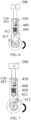
FIG. 4 is a first state diagram of parts in a movement process in an electronic device shown inFIG. 1 ; -
FIG. 5 is a second state diagram of parts in a movement process in an electronic device shown inFIG. 1 ; -
FIG. 6 is a third state diagram of parts in a movement process in an electronic device shown inFIG. 1 ; -
FIG. 7 is a fourth state diagram of parts in a movement process in an electronic device shown inFIG. 1 ; -
FIG. 8 is a fifth state diagram of parts in a movement process in an electronic device shown inFIG. 1 ; -
FIG. 9 is a schematic assembly diagram of a driving mechanism in an electronic device disclosed in embodiments of the present application; -
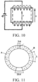
FIG. 10 is a schematic working principle diagram of a piezoelectric device in an electronic device disclosed in embodiments of the present application; -
FIG. 11 is a schematic diagram of a polarized state of a piezoelectric device in an electronic device disclosed in embodiments of the present application. -
- 100: housing, 110: positioning groove
- 200: functional device
- 300: driving mechanism, 310: piezoelectric device, 320: elastic layer, 330: wear-resistant layer
- 400: transmission mechanism, 410: cam, 411: wheel body, 412: protruding portion, 412a: guide surface, 413: rotating rod, 420: reset portion, 430: elastic portion, 440: connection portion, 450: positioning portion, 451: positioning hook, 452: blocking segment, 460: pulley
- 510: guide rail
- 600: watch band
- 700: power supply
- 800: operation button.
- To describe the purpose, the technical solutions and the advantages of the present application more clearly, the technical solutions of the present application are clearly and fully described below with reference to the specific embodiments and the corresponding accompanying drawings of the present application. Apparently, the described embodiments are merely some of the embodiments of the present application, but not all the embodiments. Based on the embodiments of the present application, all other embodiments obtained by a person of ordinary skill in the art without involving an inventive effort shall fall within the scope of protection of the present application.
- The technical solutions disclosed in various embodiments of the present application are described in detail below with reference to the accompanying drawings.
- As shown in
FIG. 1 to FIG. 11 , the embodiments of the present application disclose an electronic device which can be a smart phone, a tablet computer, an E-book reader, or a wearable device. - As shown in
FIG. 1 , the electronic device includes ahousing 100, afunctional device 200, adriving mechanism 300, and atransmission mechanism 400. An opening is formed on thehousing 100; moreover, thefunctional device 200 is movably mounted on thehousing 100; thedriving mechanism 300 is connected to thetransmission mechanism 400; and thetransmission mechanism 400 cooperates with thefunctional device 200, so that at least part of thefunctional device 200 can extend out of thehousing 100 from the opening, and thefunctional device 200 retracts into thehousing 100 from the opening. Optionally, thefunctional device 200 can include at least one of a camera, a sensor, a receiver, and a light supplementing lamp. - As shown in
FIG. 1 to FIG. 3 , thedriving mechanism 300 is mounted in thehousing 100, thedriving mechanism 300 includes apiezoelectric device 310, thepiezoelectric device 310 is made of a piezoelectric material, and thepiezoelectric device 310 vibrates when being energized. Optionally, thepiezoelectric device 310 can be of an annular structure. As shown inFIG. 10 and FIG. 11 , thepiezoelectric device 310 includes polarized A and B phase regions, the polarization directions of the A phase region and the B phase region are opposite, E is an electric field direction, and F is a polarization direction. Thepiezoelectric device 310 can be connected to apower supply 700 in the electronic device through a wire. In a case that thepower supply 700 applies an electrical signal to thepiezoelectric device 310, thepiezoelectric device 310 will alternately stretch and retract for deformation, so that thepiezoelectric device 310 can generate traveling waves rotating along an annular circumferential direction, and any point on a surface of thepiezoelectric device 310 can generate ultrasonic vibration according to an elliptical trajectory to rub with thetransmission mechanism 400, and thus, thetransmission mechanism 400 rotates. - No electromagnetic interference is generated in the working process of the
piezoelectric device 310, and there is almost no noise during working, so that the user experience is relatively good and there is no need to configure a deceleration mechanism for thedriving mechanism 300, and thus, the whole structure of the electronic device is more concise. Optionally, thepiezoelectric device 310 can be a piezoelectric ceramic formed of BaTiO3 (barium tatanate), or can also be PZT, i.e., a binary piezoelectric ceramic with the chemical formula of PbPb(Zr11xTix)O3, so that it is ensured that thepiezoelectric device 310 has good comprehensive performance. - Further, as shown in
FIG. 11 , an unpolarized region of λ/4 can be clamped between the A phase region and the B phase region, and the unpolarized region can be used as a sensor for controlling the power supply to feed back a signal, and the other region of a 3λ/4 wavelength between the A phase region and the B phase region can be used as a public region. The voltage and frequency of thepiezoelectric device 310 can be determined according to actual conditions, and are not limited herein. - As shown in
FIG. 1 to FIG. 3 andFIG. 9 , thetransmission mechanism 400 includes acam 410; thecam 410 is disposed at an inner side of thefunctional device 200, and thecam 410 is mounted on thepiezoelectric device 310; thepiezoelectric device 310 drives thecam 410 to rotate between a first location and a second location; and on the basis of the structural features of thecam 410, by mounting thecam 410 at the inner side of thefunctional device 200, in a case that a position of thecam 410 that is in contact with thefunctional device 200 is changed, a distance between the center of rotation of thecam 410 and thefunctional device 200 is also changed. - As shown in
FIG. 1 to FIG. 3 , thecam 410 can include awheel body 411 and a protrudingportion 412; the protrudingportion 412 is connected to a wheel rim of thewheel body 411; and compared with a condition that thewheel body 411 is in contact with thefunctional device 200, in a case that the protrudingportion 412 is in contact with thefunctional device 200, a distance between thefunctional device 200 and the center of rotation of thecam 410 can be larger. Therefore, in a case that the protrudingportion 412 of thecam 410 is in contact with thefunctional device 200, the location of thecam 410 can be set to be the second location, and in a case that thewheel body 411 of thecam 410 is in contact with thefunctional device 200, the location of thecam 410 can be set to be the first location. In a case that thecam 410 is at the first location, thefunctional device 200 is located in thehousing 100, and in a case that thecam 410 is at the second location, thecam 410 can drive at least part of thefunctional device 200 to extend out of thehousing 100 from the opening. It should be noted that in a case that the protrudingportion 412 of thecam 410 is not in contact with thefunctional device 200, thefunctional device 200 can retract into thehousing 100 in a manual push-back manner to be in contact with thewheel body 411 of thecam 410. - The
transmission mechanism 400 of the electronic device disclosed in the embodiments of the present application includes thecam 410, the location of thecam 410 can be changed through thepiezoelectric device 310, and the mounting and working space occupied by thetransmission mechanism 400, i.e., thecam 410, is relatively small, and thus, the structure is simple and compact, it is convenient to design and easy to manufacture, and the reliability is relatively high. In the process of using the electronic device, in a case that there is no need to use thefunctional device 200, thefunctional device 200 can retract into thehousing 100 by making thecam 410 rotate to the first location, so that thehousing 100 provides a protection function for thefunctional device 200, and prevents thefunctional device 200 from being damaged due to a collision. In a case that there is a need to use thefunctional device 200, through thepiezoelectric device 310, thecam 410 can rotate to the second location from the first location, and thecam 410 can drive at least part of thefunctional device 200 to extend out of thehousing 100 from the opening of thehousing 100, so that it is ensured that thefunctional device 200 can normally work. Moreover, because thefunctional device 200 is mounted in thehousing 100, but not on a surface of thehousing 100, thefunctional device 200 does not occupy the space, used for mounting the display screen, on thehousing 100, and thus, the area occupied by the display screen can be expanded and the screen-to-body ratio of the electronic device can be increased. - Further, as shown in
FIG. 3 , thetransmission mechanism 400 can further include areset portion 420; one end of thereset portion 420 can be connected to thefunctional device 200, and the other end of thereset portion 420 can be connected to thehousing 100; an included angle between a stretchable direction of thereset portion 420 and a movement direction of thefunctional device 200 can be β, and 0°≤β<90; in a case that thecam 410 is at the first location, thereset portion 420 is in a natural state; and in a case that thecam 410 is at the second location, thereset portion 420 is in a compressed state, or in a case that thecam 410 is at the second location, thereset portion 420 is in an extended state. - In the process of using the aforementioned structure, in a case that the
cam 410 is at the second location, thereset portion 420 stores elastic potential energy due to being stretched or compressed, so that once thecam 410 leaves the second location, thereset portion 420 has a tend to restore deformation to release the elastic potential energy; and because the stretchable direction of thereset portion 420 has a component in the movement direction of thefunctional device 200, under the action of thereset portion 420, thefunctional device 200 can automatically retract into thehousing 100. - Specifically, the
reset portion 420 can be a compression spring, and one end of the compression spring can be fixed on thehousing 100, and the other end of the compression spring can be fixed on thefunctional device 200. In the process that thefunctional device 200 moves relative to thehousing 100, the location of an end portion of the compression spring connected to thehousing 100 is not changed relative to thehousing 100, but the location of an end portion of the compression spring connected to thefunctional device 200 is changed along with the movement of thefunctional device 200 relative to thehousing 100, and therefore, by designing a mounting location of the compression spring, in a case that thecam 410 rotates to the second location, the compression spring can be in the compressed state or the extended state. - For example, in a case that the end portion of the compression spring connected to the
housing 100 and the end portion of the compression spring connected to thefunctional device 200 are arranged along an extension direction of thefunctional device 200, along with the execution of the process that thefunctional device 200 extends out of thehousing 100, the end portion of the compression spring connected to thefunctional device 200 moves towards a direction distant from the end portion of the compression spring connected to thehousing 100, so that the compression spring is stretched, and in a case that thecam 410 rotates to the second location, the compression spring can be in the extended state. Moreover, in a case that the end portion of the compression spring connected to thehousing 100 and the end portion of the compression spring connected to thefunctional device 200 are arranged along a retraction direction of thefunctional device 200, along with the execution of the process that thefunctional device 200 extends out of thehousing 100, the end portion of the compression spring connected to thefunctional device 200 moves towards a direction close to the end portion of the compression spring connected to thehousing 100, so that the compression spring is compressed, and in a case that thecam 410 rotates to the second location, the compression spring can be in the compressed state. - More specifically, as shown in
FIG. 3 , the stretchable direction of the compression spring can be parallel to the movement direction of thefunctional device 200, and thus, on one hand, the elastic function of the compression spring can be prevented from having a negative influence on other components, and on the other hand, the automatic retraction speed and thoroughness of thefunctional device 200 can further be improved. Optionally, as shown inFIG. 3 , the compression spring can be mounted between thefunctional device 200 and thecam 410, and in a case that thecam 410 rotates to the second location, the compression spring can be in the compressed state, so that the mounting space in the electronic device can be well utilized. - Further, the
transmission mechanism 400 further includes aconnection portion 440; thefunctional device 200 is connected to one end of theconnection portion 440, and the other end of theconnection portion 440 is engaged with thecam 410, so that the engagement difficulty between thecam 410 and thefunctional device 200 is reduced through theconnection portion 440. In detail, in the case that theconnection portion 440 is provided, a distance between the mounting location of thecam 410 and the opening can be relatively large, so that it is ensured that there is a certain distance between the protrudingportion 412 of thecam 410 and an edge of thehousing 100, and in a case that thecam 410 drives thefunctional device 200 to extend out, the protrudingportion 412 of thecam 410 can be prevented from being in contact with the edge of thehousing 100. - Specifically, the
connection portion 440 can be of a rod-shaped connection structure, can be fixedly connected to thefunctional device 200 in a bonding manner and the like, or can further fix thefunctional device 200 to one end of theconnection portion 440 through a connection member, such as a bolt. The size and shape of theconnection portion 440 can be determined according to actual conditions. - Optionally, the electronic device disclosed in the embodiments of the present application can further include a
guide rail 510; theguide rail 510 is fixed on thehousing 100; and by enabling theconnection portion 440 to be in movable engagement with theguide rail 510 along the movement direction, and enabling theconnection portion 440 to engage with theguide rail 510 in a limiting manner along a direction perpendicular to the movement direction, the movement direction of theconnection portion 440 can be limited, and it can be prevented that thecam 410 cannot move in the process of driving thefunctional device 200 through theconnection portion 440 because thefunctional device 200 is stuck in the opening due to the deflection of theconnection portion 440. - Specifically, the
guide rail 510 can be a limiting structure corresponding to the structure of theconnection portion 440. For example, theconnection portion 440 can be a rectangular rod-shaped structure, and then theguide rail 510 can be a rectangular cylindrical structure. Theconnection portion 440 is disposed in theguide rail 510, so that theconnection portion 440 only can move along the movement direction of thefunctional device 200, and theguide rail 510 can further provide a certain guide function for theconnection portion 440 to a certain extent, and improve the movement stability of theconnection portion 440 and thefunctional device 200. Of course, theguide rail 510 can further be another type of component. For the consideration of brevity, details are not described again. - In the process of using the electronic device, in a case that the
functional device 200 is supported directly through thecam 410, thefunctional device 200 keeps the extended state, so that thecam 410 is frequently subjected to a shear force for a long time, which easily breaks a connection relationship between thecam 410 and thepiezoelectric device 310, and the actual location of thecam 410 is affected by the working state of thepiezoelectric device 310. If thepiezoelectric device 310 accidentally acts, it may cause that thecam 410 vibrates or rotates, and thus, the cam cannot provide a stable support effect for thefunctional device 200. - Further, the transmission mechanism further includes a
positioning portion 450; thepositioning portion 450 is hingedly connected to theconnection portion 440; thepositioning portion 450 includes apositioning hook 451; and in a case that thecam 410 is at the second location, thepositioning hook 451 is engaged with thepositioning groove 110 in a limiting manner to limit thefunctional device 200 to retract into thehousing 100 from the opening. In the process of using the aforementioned structure, in a case that at least part of thefunctional device 200 extends out of thehousing 100, by enabling thepositioning hook 451 to cooperate with thepositioning groove 110, it can be ensured that a stable relative fixed relationship can be formed between thefunctional device 200 and thehousing 100, and the service lives of thecam 410 and thepiezoelectric device 310 can be prolonged to a certain extent. - Specifically, as shown in
FIG. 3 , thepositioning groove 110 can be formed at a location of thehousing 100 corresponding to thepositioning hook 451, so that in the process that thecam 410 drives theconnection portion 440 to move, thepositioning hook 451 is gradually close to thepositioning groove 110, and in a case that thepositioning hook 451 reaches the location of thepositioning groove 110, thepositioning hook 451 can stretch into thepositioning groove 110, and even though after thecam 410 is detached from the second location, thefunctional device 200 can also fail to automatically retract into thehousing 100, so that it is ensured that thefunctional device 200 can be stable in the state of extending out of thehousing 100. - Correspondingly, in a case that there is a need to enable the
functional device 200 to retract into thehousing 100, on one hand, it is needed to ensure that thecam 410 rotates to the first location, and on the other hand, it is needed to enable thepositioning hook 451 to be detached from thepositioning groove 110, so that a limiting engagement relationship between thepositioning hook 451 and thepositioning groove 110 is broken. Optionally, through a corresponding connection structure, thepositioning hook 451 can be detached from thepositioning groove 110 in a manual operation manner, such as pulling thepositioning hook 451. - Further, in order to enable the
positioning hook 451 to be able to more easily form the limiting engagement relationship with thepositioning groove 110, optionally, as shown inFIG. 3 , thetransmission mechanism 400 can further include anelastic portion 430; one end of theelastic portion 430 can be connected to thepositioning hook 451, and the other end of theelastic portion 430 can be connected to thehousing 100; an included angle between a stretchable direction of theelastic portion 430 and the movement direction of thefunctional device 200 is γ, and 0°<γ≤90°; and in a case that thecam 410 is at the first location, theelastic portion 430 is in an extended state or a compressed state. - In the process of using the aforementioned structure, in a case that the
cam 410 is at the first location, theelastic portion 430 stores elastic potential energy due to being stretched or compressed, so that once thecam 410 leaves the first location, theelastic portion 430 has a tend to restore deformation to release the elastic potential energy; and because the stretchable direction of theelastic portion 430 has a component in a direction perpendicular to the movement direction of thefunctional device 200, no matter whether there are other influence factors, in a case that thepositioning hook 451 moves to the location of thepositioning groove 110, under the action of theelastic portion 430, it can be ensured that thepositioning hook 451 can form a reliable limiting engagement relationship with thepositioning groove 110. - Optionally, as shown in
FIG. 3 , in a case that thepositioning hook 451 is engaged with thepositioning groove 110 in a limiting manner, the stretchable direction of theelastic portion 430 can be perpendicular to the movement direction of thefunctional device 200, and this can maximally prevent the occurrence of a phenomenon that thepositioning hook 451 is accidentally detached from thepositioning groove 110. Theelastic portion 430 can be an extension spring, and theelastic portion 430 is disposed between thepositioning hook 451 and thepositioning groove 110, so that the space between thepositioning hook 451 and thepositioning groove 110 is effectively utilized. - According to the invention, the
positioning portion 450 further includes ablocking segment 452; the blockingsegment 452 is connected to thepositioning hook 451, and is located at one side of a hinge point of thepositioning portion 450 facing away from thepositioning hook 451; in the process that thecam 410 rotates to the first location from the second location, thecam 410 can be in contact with the blockingsegment 452; and because theblocking segment 452 and thepositioning hook 451 are respectively at the opposite two sides of the hinge point of thepositioning portion 450, thecam 410 can drive thepositioning hook 451 to be detached from thepositioning groove 110, so that it is ensured that thefunctional device 200 can retract into thehousing 100. It should be noted that the relationships among the orientation of thepositioning hook 451, the location of the blockingsegment 452, and the rotation direction of thecam 410 can be correspondingly set according to actual requirements. - In order to reduce the design difficulty and control difficulty of the electronic device, the electric field direction cannot be changed in the working process of the electronic device, so that the
piezoelectric device 310 drives thecam 410 to always rotate along the same direction. As shown inFIG. 4 to FIG. 8 , in a case that thecam 410 clockwise rotates to the second location from the first location, thecam 410 can drive thefunctional device 200 to extend out of thehousing 100; and as shown in the figures, in a case that thecam 410 continues to clockwise rotate to the first location from the second location, thefunctional device 200 can retract into thehousing 100. - In a case that the
cam 410 always rotates along the same direction, more specifically, in a case that thecam 410 clockwise rotates, in order to more clearly describe the mutual relationships among thepositioning hook 451, the blockingsegment 452, and thecam 410, by taking the electronic device shown inFIG. 6 as an example, thefunctional device 200 is disposed above thecam 410, and thepositioning hook 451 can be rightwards disposed, so that in the process that thecam 410 drives theconnection portion 440 to upwards move, thepositioning hook 451 can form the limiting engagement relationship with thepositioning groove 110, so as to limit thefunctional device 200 from retracting into thehousing 100. Meanwhile, the blockingsegment 452 can be disposed at the right side of thepositioning hook 451, i.e., at the downstream of thepositioning hook 451. In the process that thecam 410 clockwise rotates, thecam 410 first cooperates with thepositioning hook 451, and after thecam 410 continues to rotate by a certain angle, the blockingsegment 452 can be in contact with thecam 410. Because the blockingsegment 452 and thepositioning hook 451 are located at the opposite two sides of the hinge point, in a case that thecam 410 drives the blockingsegment 452 to rotate, the blockingsegment 452 moves towards an upper right direction and thepositioning hook 451 moves towards a lower left direction and can be detached from thepositioning groove 110, and then under the action of thereset portion 420, thefunctional device 200 can automatically retract into thehousing 100. - Optionally, the
cam 410 can further include arotating rod 413; therotating rod 413 is connected to thewheel body 411; in the process that thecam 410 rotates towards the first location from the second location, therotating rod 413 is in contact with the blockingsegment 452 to drive thepositioning hook 451 to be detached from thepositioning groove 110. By additionally providing therotating rod 413 and enabling therotating rod 413 to engage with the blockingsegment 452, the functions and roles of the components in thecam 410 are more single, so that in the process of structure design, the design difficulty of the protrudingportion 412, therotating rod 413, the blockingsegment 452 and other components is reduced. - Moreover, in order to prevent the protruding
portion 412 from colliding with the blockingsegment 452 during rotation, optionally, therotating rod 413 and the protrudingportion 412 can be arranged along the axial direction of thewheel body 411, and the blockingsegment 452 is located at one side of thewheel body 411 where therotating rod 413 is located, so that the blockingsegment 452 and the protrudingportion 412 are located at different planes, and it is ensured that the protrudingportion 412 does not collide with the blockingsegment 452 in the process of rotating along with thewheel body 411. - In a case that the
cam 410 always rotates along the same direction, in order to enable the response speeds of thefunctional device 200 in the extension process and in the retraction process to relatively approach to each other, optionally, a preset included angle can be formed between the protrudingportion 412 and therotating rod 413, so that in the processes that thefunctional device 200 extends and retracts, the angles by which the protrudingportion 412 rotates are closer to each other, and thus, it is prevented that the response speed of an extension action or a retraction action of thefunctional device 200 is too slow, and the user experience is improved. - Further, as shown in
FIG. 3 , aguide surface 412a can be formed on the protrudingportion 412, and the location of theguide surface 412a is associated with the rotation direction of thecam 410. Specifically, in the process that thecam 410 rotates to the second location from the first location, a surface of the protrudingportion 412 that is in contact with thefunctional device 200 is theguide surface 412a, and under the action of theguide surface 412a, thefunctional device 200 can more easily move onto the protrudingportion 412 of thecam 410 from thewheel body 411 of thecam 410, and the movement process of thefunctional device 200 can be smoother and more stable. Specifically, as shown inFIG. 3 , a guide portion can be an inclined plane, or theguide surface 412a can also a smooth curved surface. Of course, in a case that thefunctional device 200 is connected to one end of theconnection portion 440, in the process that thecam 410 rotates to the second location from the first location, the end portion of theconnection portion 440 facing away from thefunctional device 200 is in contact with theguide surface 412a of the protrudingportion 412. - In order to further ensure that the
cam 410 can more reliably drive thefunctional device 200 to move, optionally, the transmission mechanism can further include apulley 460. Thepulley 460 is fixed to one end of thefunctional device 200 facing thecam 410, and thepulley 460 is movably connected to thehousing 100 along the movement direction of thefunctional device 200. In the process that thecam 410 rotates, thecam 410 can engage with thepulley 460 in a rolling manner, and this can reduce the rotation resistance of thecam 410. Moreover, in a case that the protrudingportion 412 of thecam 410 rotates to a location where thepulley 460 is located, thepulley 460 can further provide a certain guide function for the rotation of the protrudingportion 412, and thus, it is easier for the protrudingportion 412 of thecam 410 to rotate between thepulley 460 and thewheel body 411, so as to drive thepulley 460 to move towards a direction facing away from thewheel body 411 to drive thefunctional device 200 to extend out of thehousing 100. - Specifically, the axle of the
pulley 460 can be movably connected to thehousing 100, and thefunctional device 200 can be connected to the axle of thepulley 460. Optionally, thefunctional device 200 can be connected to the axle of thepulley 460 through theconnection portion 440. In addition, as shown inFIG. 2 , thereset portion 420 can be sleeved on theconnection portion 440, so that theconnection portion 440 can further provide a certain guide function for thereset portion 420, and prevent thereset portion 420 from being bent or deformed when being compressed. Optionally, one end of thereset portion 420 can be fixed on thehousing 100, and the other end of the reset portion can be fixed on theconnection portion 440. - Further, the
driving mechanism 300 can further include a wear-resistant layer 330. The wear-resistant layer 330 can be fixed at one side of thecam 410 facing thepiezoelectric device 310, so that in the working process of thepiezoelectric device 310, by enabling the wear-resistant layer 330 to be in contact with thepiezoelectric device 310, the service life of thetransmission mechanism 400 can be prolonged, and thecam 410 can be prevented from being damaged. Optionally, the wear-resistant layer 330 can be formed of a carbon nano-material, and a thickness of the wear-resistant layer can be determined according to an actual requirement. - Optionally, the
driving mechanism 300 can further include anelastic layer 320; theelastic layer 320 is an elastic structural member, and theelastic layer 320 can be fixed to one side of thepiezoelectric device 310 facing thecam 410 in a bonding manner and the like; and theelastic layer 320 can generate a relatively large amount of deformation in the working process of thepiezoelectric device 310, and under the action of a larger amount of deformation, it can further be ensured that thecam 410 can generate a rotation action along a preset direction. Optionally, theelastic layer 320 can be formed of a metal copper material and be of a sheet-shaped structure, so that it is ensured that theelastic layer 320 has a relatively large elastic capability and further has relatively high structural strength. In a case that the electronic device is a smart watch, thepiezoelectric device 310 can be disposed parallel to a dial to reduce the whole thickness of the electronic device. In addition, as shown inFIG. 1 , anoperation button 800 can further be disposed on a watch case, and theoperation button 800 can be disposed at one side of the watch case facing away from the opening. In the process of using the electronic device, a corresponding operation can be performed on the electronic device through theoperation button 800. For example, a volume adjustment function of the electronic device can be implemented through theoperation button 800, and correspondingly, thefunctional device 200 can also be driven to move through theoperation button 800. - Optionally, the electronic device disclosed in the embodiments of the present application is the smart watch; the
housing 100 can be the watch case; the smart watch further includes awatch band 600; and thewatch band 600 is connected to the watch case. The watch case can be formed of a metal and the like, and can be a square structure, a round structure, or the like. Thewatch band 600 can be formed of plastic, a fiber, a corium, or the like; a clamping detachable connection relationship between thewatch band 600 and the watch case can be formed through a spring bar; and thewatch band 600 can be of a segmented structure, and can also be of an integrated structure. - Further, a preset included angle α is formed between the
watch band 600 and the opening of thehousing 100, and 0°<α≤90°. In this case, thefunctional device 200 can be prevented from being hindered by thewatch band 600 as much as possible in the process of extending out of thehousing 100. Optionally, the preset included angle α between thewatch band 600 and the opening can be equal to 90°, so that thewatch band 600 and the opening are located at different sides of thehousing 100, and thewatch band 600 can be maximally prevented from hindering the extension and retraction processes of thefunctional device 200. - The descriptions of the aforementioned embodiments of the present application focus on differences between the embodiments. As long as different optimized features between the embodiments are not contradictory, they can be combined to form a more preferred embodiment. Further descriptions are omitted herein for the purpose of brevity.
- The foregoing descriptions are only for the embodiments of the present application, but are not intended to limit the present application. Persons skilled in the art can make modifications and variations on the present application. Any modifications, improvements, etc. made within the principle of the present application should be included within the scopes of protection of the claims of the present application.
Claims (12)
- An electronic device comprising:a housing (100), provided with an opening and a positioning groove (110);a functional device (200), movably mounted on the housing (100);a driving mechanism (300), mounted in the housing (100) and comprising a piezoelectric device (310), wherein the piezoelectric device (310) is adapted to vibrate when being energized; anda transmission mechanism (400), comprising a cam (410), a connection portion (440) and a positioning portion (450), wherein the functional device is connected to one end of the connection portion (440), and the other end of the connection portion (440) is configured to engage with the cam (410), the positioning portion (450) is hingedly connected to the connection portion (440); the positioning portion (450) comprises a positioning hook (451), the cam (410) is disposed at an inner side of the functional device (200), the cam (410) comprises a wheel body (411) and a protruding portion (412), the protruding portion (412) is disposed at a wheel rim of the wheel body (411), the wheel body (411) is mounted on the piezoelectric device (310), and the piezoelectric device (310) is adapted to drive the cam (410) to rotate between a first location and a second location,wherein in a case that the cam (410) is at the first location, the functional device (200) is located in the housing (100), and in a case that the cam (410) is at the second location, the protruding portion (412) is adapted to drive at least part of the functional device (200) to extend out of the housing (100) from the opening; and in a case that the cam (410) is at the second location, the positioning hook (451) is engaged with the positioning groove (110) in a limiting manner to limit the functional device (200) to retract into the housing (100) from the opening,wherein the positioning portion (450) further comprises a blocking segment (452); the blocking segment (452) is connected to the positioning hook (451), and the blocking segment (452) is located at one side of a hinge point of the positioning portion (450) facing away from the positioning hook (451); and in the process that the cam (410) rotates towards the first location from the second location, the cam (410) is in contact with the blocking segment (452) to drive the positioning hook (451) to be detached from the positioning groove (110).
- The electronic device according to claim 1, wherein the transmission mechanism (400) further comprises a reset portion (420); one end of the reset portion (420) is connected to the functional device (200), and the other end of the reset portion (420) is connected to the housing (100); an included angle between a stretchable direction of the reset portion (420) and a movement direction of the functional device (200) is β, and 0°≤β<90; in a case that the cam (410) is at the first location, the reset portion (420) is in a natural state; and in a case that the cam (410) is at the second location, the reset portion (420) is in a compressed state, or in a case that the cam (410) is at the second location, the reset portion (420) is in an extended state.
- The electronic device according to claim 1, wherein the transmission mechanism (400) further comprises an elastic portion (430); one end of the elastic portion (430) is connected to the positioning hook (451), and the other end of the elastic portion (430) is connected to the housing (100); an included angle between a stretchable direction of the elastic portion (430) and a movement direction of the functional device (200) is γ, and 0°<γ≤90°; and in a case that the cam (410) is at the first location, the elastic portion (430) is in an extended state or a compressed state.
- The electronic device according to claim 1, wherein the cam (410) further comprises a rotating rod (413); the rotating rod (413) is connected to the wheel body (411); the rotating rod (413) and the protruding portion (412) are arranged along an axial direction of the wheel body (411), and the blocking segment (452) is located at one side of the wheel body (411) where the rotating rod (413) is located; and in the process that the cam (410) rotates towards the first location from the second location, the rotating rod (413) is in contact with the blocking segment (452) to drive the positioning hook (451) to be detached from the positioning groove (110).
- The electronic device according to claim 1, further comprising a guide rail (510), wherein the guide rail (510) is fixed to the housing (100); the connection portion (440) is in movable engagement with the guide rail (510) along the movement direction; and the connection portion (440) is engaged with the guide rail (510) in a limiting manner along a direction perpendicular to the movement direction.
- The electronic device according to claim 1, wherein the protruding portion (412) is provided with a guide surface (412a); and in the process that the cam (410) rotates towards the second location from the first location, a surface of the protruding portion (412) that is in contact with the connection portion (440) is the guide surface (412a).
- The electronic device according to claim 1, wherein the transmission mechanism (400) further comprises a pulley (460); the pulley (460) is fixed to one end of the functional device (200) facing the cam (410), and the pulley (460) is movably connected to the housing (100) along the movement direction of the functional device (200); and the cam (410) is engaged with the pulley (460) in a rolling manner.
- The electronic device according to claim 1, wherein the driving mechanism (300) further comprises a wear-resistant layer (330); and the wear-resistant layer (330) is fixed to one side of the cam (410) facing the piezoelectric device (310).
- The electronic device according to claim 1, wherein the driving mechanism (300) further comprises an elastic layer (320); the elastic layer (320) is an elastic structural member; and the elastic layer (320) is fixed to one side of the piezoelectric device (310) facing the cam (410).
- The electronic device according to claim 1, wherein the electronic device is a smart watch; the housing (100) is a watch case; the smart watch further comprises a watch band (600); and the watch band (600) is connected to the watch case.
- The electronic device according to claim 10, wherein a preset included angle α is formed between the watch band (600) and the opening, and 0°<α≤90°.
- The electronic device according to claim 10, wherein the functional device (200) comprises at least one of a camera, a sensor, a receiver, and a light supplementing lamp.
Applications Claiming Priority (2)
| Application Number | Priority Date | Filing Date | Title |
|---|---|---|---|
| CN202010463367.2A CN111614817B (en) | 2020-05-27 | 2020-05-27 | Electronic device |
| PCT/CN2021/095943 WO2021238959A1 (en) | 2020-05-27 | 2021-05-26 | Electronic apparatus |
Publications (3)
| Publication Number | Publication Date |
|---|---|
| EP4161037A1 EP4161037A1 (en) | 2023-04-05 |
| EP4161037A4 EP4161037A4 (en) | 2023-11-08 |
| EP4161037B1 true EP4161037B1 (en) | 2024-08-28 |
Family
ID=72204454
Family Applications (1)
| Application Number | Title | Priority Date | Filing Date |
|---|---|---|---|
| EP21812463.4A Active EP4161037B1 (en) | 2020-05-27 | 2021-05-26 | Electronic apparatus |
Country Status (7)
| Country | Link |
|---|---|
| US (1) | US12239023B2 (en) |
| EP (1) | EP4161037B1 (en) |
| JP (1) | JP7459304B2 (en) |
| KR (1) | KR102754558B1 (en) |
| CN (1) | CN111614817B (en) |
| ES (1) | ES2991775T3 (en) |
| WO (1) | WO2021238959A1 (en) |
Families Citing this family (3)
| Publication number | Priority date | Publication date | Assignee | Title |
|---|---|---|---|---|
| CN111614817B (en) | 2020-05-27 | 2021-06-04 | 维沃移动通信有限公司 | Electronic device |
| CN114598759B (en) * | 2020-12-07 | 2026-03-27 | 北京小米移动软件有限公司 | electronic devices |
| CN116014513A (en) * | 2023-01-03 | 2023-04-25 | 维沃移动通信有限公司 | Adjustment device and connection line assembly |
Family Cites Families (37)
| Publication number | Priority date | Publication date | Assignee | Title |
|---|---|---|---|---|
| JPS5199270U (en) * | 1975-02-08 | 1976-08-09 | ||
| JPH01157594A (en) | 1987-12-14 | 1989-06-20 | Nec Corp | Automatic cleaning type image display device |
| JPH0713437Y2 (en) * | 1988-04-18 | 1995-03-29 | 富士写真フイルム株式会社 | Shutter mechanism |
| JPH09314968A (en) * | 1996-05-31 | 1997-12-09 | Mitsubishi Electric Corp | Printer device |
| JPH10127068A (en) * | 1996-10-21 | 1998-05-15 | Nikon Corp | Rotary motor |
| KR100643974B1 (en) | 2002-03-11 | 2006-11-10 | 세이코 엡슨 가부시키가이샤 | Rotation / Move Conversion Actuator |
| CN101206297B (en) | 2006-12-20 | 2011-09-28 | 财团法人工业技术研究院 | Piezo Driven Optical Lens |
| US20090005135A1 (en) * | 2007-06-29 | 2009-01-01 | Nokia Corporation | Electronic device slide mechanism |
| KR101636909B1 (en) * | 2009-02-03 | 2016-07-06 | 삼성전자주식회사 | Piezoelectric ultrasonic motor and method for fabricating the same |
| CN105141815B (en) * | 2015-09-02 | 2018-07-31 | 小米科技有限责任公司 | Camera automatic pop-up device and terminal |
| CN107991827B (en) * | 2016-10-26 | 2020-08-18 | Tdk株式会社 | Lens driving device |
| KR101893166B1 (en) * | 2017-04-28 | 2018-08-29 | 엘지전자 주식회사 | The mobile terminal module and the watch type mobile terminal |
| CN107197133B (en) | 2017-07-21 | 2019-11-29 | 维沃移动通信有限公司 | A kind of mobile terminal and CCD camera assembly |
| EP3481035B1 (en) * | 2017-11-03 | 2020-07-29 | Guangdong Oppo Mobile Telecommunications Corp., Ltd. | Mobilephone camera slidable by electromagnetic force |
| CN109862236B (en) * | 2017-11-30 | 2020-07-10 | Oppo广东移动通信有限公司 | Camera assembly, mobile terminal and control method of camera assembly |
| CN109962995B (en) * | 2017-12-14 | 2021-03-12 | Oppo广东移动通信有限公司 | Functional assembly, electronic device and control method thereof |
| CN109963001B (en) * | 2017-12-22 | 2020-12-22 | Oppo广东移动通信有限公司 | Functional component, electronic device and control method thereof |
| CN109981937A (en) | 2017-12-28 | 2019-07-05 | 广东欧珀移动通信有限公司 | Electronic equipment and camera assembly thereof |
| CN109995905B (en) * | 2017-12-29 | 2021-01-22 | Oppo广东移动通信有限公司 | Functional module, electronic device and control method of electronic device |
| KR102493579B1 (en) | 2018-01-08 | 2023-01-31 | 삼성전자주식회사 | Electronic device including camera and method for controlling the electronic device |
| CN208052117U (en) * | 2018-03-05 | 2018-11-06 | 广州市合成电子制品有限公司 | A kind of PCB whole plates automatic cutting lathe |
| CN108494286B (en) * | 2018-04-27 | 2019-11-08 | 哈尔滨工业大学 | Torsion-type precision piezoelectric driver adopting shear working mode and manufacturing method thereof |
| CN108811416B (en) * | 2018-06-06 | 2020-04-21 | Oppo(重庆)智能科技有限公司 | Electronic equipment |
| WO2019237993A1 (en) * | 2018-06-12 | 2019-12-19 | 宁波舜宇光电信息有限公司 | Camera unit with light deflection mechanism, and application thereof |
| CN108924310B (en) * | 2018-07-25 | 2021-01-08 | 维沃移动通信有限公司 | Mobile terminal |
| CN208572158U (en) * | 2018-08-27 | 2019-03-01 | 珠海格力电器股份有限公司 | Mobile terminal |
| CN109246342A (en) * | 2018-09-27 | 2019-01-18 | 维沃移动通信有限公司 | Mobile terminal |
| CN210129880U (en) * | 2019-01-24 | 2020-03-06 | Oppo广东移动通信有限公司 | Mobile terminal |
| CN110086902B (en) * | 2019-04-02 | 2021-01-08 | 维沃移动通信(杭州)有限公司 | Terminal device and control method of terminal device |
| CN111835887B (en) * | 2019-04-16 | 2022-04-08 | 北京小米移动软件有限公司 | Camera structure and electronics |
| CN110601596B (en) * | 2019-05-09 | 2022-07-01 | 山东理工大学 | A Standing Wave Magnetic Repulsion Unidirectional Rotary Motor Based on Piezoelectric Ceramics |
| CN210578670U (en) * | 2019-07-12 | 2020-05-19 | 深圳传音控股股份有限公司 | Camera telescopic mechanism and mobile terminal |
| CN110557480B (en) * | 2019-08-01 | 2021-05-14 | 维沃移动通信(杭州)有限公司 | Electronic equipment |
| CN110545369B (en) * | 2019-08-20 | 2021-01-08 | 维沃移动通信(杭州)有限公司 | Electronic device |
| CN110545346A (en) | 2019-10-09 | 2019-12-06 | Oppo广东移动通信有限公司 | Electronic equipment |
| CN110933210B (en) * | 2019-12-26 | 2021-07-06 | 维沃移动通信有限公司 | Electronic equipment |
| CN111614817B (en) * | 2020-05-27 | 2021-06-04 | 维沃移动通信有限公司 | Electronic device |
-
2020
- 2020-05-27 CN CN202010463367.2A patent/CN111614817B/en active Active
-
2021
- 2021-05-26 ES ES21812463T patent/ES2991775T3/en active Active
- 2021-05-26 EP EP21812463.4A patent/EP4161037B1/en active Active
- 2021-05-26 KR KR1020227045488A patent/KR102754558B1/en active Active
- 2021-05-26 WO PCT/CN2021/095943 patent/WO2021238959A1/en not_active Ceased
- 2021-05-26 JP JP2022572709A patent/JP7459304B2/en active Active
-
2022
- 2022-11-21 US US17/991,440 patent/US12239023B2/en active Active
Also Published As
| Publication number | Publication date |
|---|---|
| ES2991775T3 (en) | 2024-12-04 |
| EP4161037A1 (en) | 2023-04-05 |
| EP4161037A4 (en) | 2023-11-08 |
| CN111614817B (en) | 2021-06-04 |
| CN111614817A (en) | 2020-09-01 |
| KR102754558B1 (en) | 2025-01-14 |
| US20230089414A1 (en) | 2023-03-23 |
| KR20230012068A (en) | 2023-01-25 |
| JP7459304B2 (en) | 2024-04-01 |
| JP2023532406A (en) | 2023-07-28 |
| WO2021238959A1 (en) | 2021-12-02 |
| US12239023B2 (en) | 2025-02-25 |
Similar Documents
| Publication | Publication Date | Title |
|---|---|---|
| US12239023B2 (en) | Electronic device | |
| US12298658B2 (en) | Aperture, camera module, and electronic device | |
| US11023019B2 (en) | Mobile terminal | |
| KR101899502B1 (en) | Hinge device and computing apparatus having the same | |
| CN113840482B (en) | electronic device | |
| CN114900572B (en) | Housing components and electronic equipment | |
| EP4160577B1 (en) | Electronic device | |
| CN114501915A (en) | Electronic device | |
| CN115755491A (en) | Iris diaphragm, harmonic oscillator, lens assembly and electronic equipment | |
| CN113286022A (en) | Electronic device | |
| CN109862234B (en) | Functional component, mobile terminal and control method thereof | |
| CN1114967C (en) | Method and apparatus for automatically extracting and retracting antenna in wireless telephone | |
| CN110933210B (en) | Electronic equipment | |
| CN113362710B (en) | Electronic device | |
| CN113572877B (en) | Foldable electronic device | |
| EP4156657A1 (en) | Electronic device | |
| CN110336900A (en) | Camera module and mobile terminal | |
| CN111650827A (en) | Electronic equipment | |
| CN109922182B (en) | Terminal device | |
| CN110087428A (en) | Mobile terminal | |
| EP4131899B1 (en) | Electronic device | |
| CN111090232B (en) | Electronic device | |
| CN109831552B (en) | Camera device and mobile terminal | |
| CN113783978A (en) | Electronic equipment | |
| CN111542189A (en) | Electronic device |
Legal Events
| Date | Code | Title | Description |
|---|---|---|---|
| STAA | Information on the status of an ep patent application or granted ep patent |
Free format text: STATUS: THE INTERNATIONAL PUBLICATION HAS BEEN MADE |
|
| PUAI | Public reference made under article 153(3) epc to a published international application that has entered the european phase |
Free format text: ORIGINAL CODE: 0009012 |
|
| STAA | Information on the status of an ep patent application or granted ep patent |
Free format text: STATUS: REQUEST FOR EXAMINATION WAS MADE |
|
| 17P | Request for examination filed |
Effective date: 20221222 |
|
| AK | Designated contracting states |
Kind code of ref document: A1 Designated state(s): AL AT BE BG CH CY CZ DE DK EE ES FI FR GB GR HR HU IE IS IT LI LT LU LV MC MK MT NL NO PL PT RO RS SE SI SK SM TR |
|
| DAV | Request for validation of the european patent (deleted) | ||
| DAX | Request for extension of the european patent (deleted) | ||
| A4 | Supplementary search report drawn up and despatched |
Effective date: 20231009 |
|
| RIC1 | Information provided on ipc code assigned before grant |
Ipc: H02N 2/10 20060101ALI20231002BHEP Ipc: H10N 30/20 20230101ALI20231002BHEP Ipc: G06F 3/01 20060101ALI20231002BHEP Ipc: G06F 1/16 20060101ALI20231002BHEP Ipc: H04N 23/57 20230101ALI20231002BHEP Ipc: H04M 1/02 20060101AFI20231002BHEP |
|
| GRAP | Despatch of communication of intention to grant a patent |
Free format text: ORIGINAL CODE: EPIDOSNIGR1 |
|
| STAA | Information on the status of an ep patent application or granted ep patent |
Free format text: STATUS: GRANT OF PATENT IS INTENDED |
|
| INTG | Intention to grant announced |
Effective date: 20240607 |
|
| GRAS | Grant fee paid |
Free format text: ORIGINAL CODE: EPIDOSNIGR3 |
|
| GRAA | (expected) grant |
Free format text: ORIGINAL CODE: 0009210 |
|
| STAA | Information on the status of an ep patent application or granted ep patent |
Free format text: STATUS: THE PATENT HAS BEEN GRANTED |
|
| AK | Designated contracting states |
Kind code of ref document: B1 Designated state(s): AL AT BE BG CH CY CZ DE DK EE ES FI FR GB GR HR HU IE IS IT LI LT LU LV MC MK MT NL NO PL PT RO RS SE SI SK SM TR |
|
| REG | Reference to a national code |
Ref country code: CH Ref legal event code: EP |
|
| REG | Reference to a national code |
Ref country code: DE Ref legal event code: R096 Ref document number: 602021018069 Country of ref document: DE |
|
| REG | Reference to a national code |
Ref country code: IE Ref legal event code: FG4D |
|
| REG | Reference to a national code |
Ref country code: NL Ref legal event code: FP |
|
| REG | Reference to a national code |
Ref country code: ES Ref legal event code: FG2A Ref document number: 2991775 Country of ref document: ES Kind code of ref document: T3 Effective date: 20241204 |
|
| REG | Reference to a national code |
Ref country code: LT Ref legal event code: MG9D |
|
| PG25 | Lapsed in a contracting state [announced via postgrant information from national office to epo] |
Ref country code: NO Free format text: LAPSE BECAUSE OF FAILURE TO SUBMIT A TRANSLATION OF THE DESCRIPTION OR TO PAY THE FEE WITHIN THE PRESCRIBED TIME-LIMIT Effective date: 20241128 |
|
| REG | Reference to a national code |
Ref country code: AT Ref legal event code: MK05 Ref document number: 1719189 Country of ref document: AT Kind code of ref document: T Effective date: 20240828 |
|
| PG25 | Lapsed in a contracting state [announced via postgrant information from national office to epo] |
Ref country code: PL Free format text: LAPSE BECAUSE OF FAILURE TO SUBMIT A TRANSLATION OF THE DESCRIPTION OR TO PAY THE FEE WITHIN THE PRESCRIBED TIME-LIMIT Effective date: 20240828 Ref country code: GR Free format text: LAPSE BECAUSE OF FAILURE TO SUBMIT A TRANSLATION OF THE DESCRIPTION OR TO PAY THE FEE WITHIN THE PRESCRIBED TIME-LIMIT Effective date: 20241129 Ref country code: PT Free format text: LAPSE BECAUSE OF FAILURE TO SUBMIT A TRANSLATION OF THE DESCRIPTION OR TO PAY THE FEE WITHIN THE PRESCRIBED TIME-LIMIT Effective date: 20241230 Ref country code: FI Free format text: LAPSE BECAUSE OF FAILURE TO SUBMIT A TRANSLATION OF THE DESCRIPTION OR TO PAY THE FEE WITHIN THE PRESCRIBED TIME-LIMIT Effective date: 20240828 |
|
| PG25 | Lapsed in a contracting state [announced via postgrant information from national office to epo] |
Ref country code: BG Free format text: LAPSE BECAUSE OF FAILURE TO SUBMIT A TRANSLATION OF THE DESCRIPTION OR TO PAY THE FEE WITHIN THE PRESCRIBED TIME-LIMIT Effective date: 20240828 |
|
| PG25 | Lapsed in a contracting state [announced via postgrant information from national office to epo] |
Ref country code: LV Free format text: LAPSE BECAUSE OF FAILURE TO SUBMIT A TRANSLATION OF THE DESCRIPTION OR TO PAY THE FEE WITHIN THE PRESCRIBED TIME-LIMIT Effective date: 20240828 |
|
| PG25 | Lapsed in a contracting state [announced via postgrant information from national office to epo] |
Ref country code: IS Free format text: LAPSE BECAUSE OF FAILURE TO SUBMIT A TRANSLATION OF THE DESCRIPTION OR TO PAY THE FEE WITHIN THE PRESCRIBED TIME-LIMIT Effective date: 20241228 Ref country code: AT Free format text: LAPSE BECAUSE OF FAILURE TO SUBMIT A TRANSLATION OF THE DESCRIPTION OR TO PAY THE FEE WITHIN THE PRESCRIBED TIME-LIMIT Effective date: 20240828 |
|
| PG25 | Lapsed in a contracting state [announced via postgrant information from national office to epo] |
Ref country code: HR Free format text: LAPSE BECAUSE OF FAILURE TO SUBMIT A TRANSLATION OF THE DESCRIPTION OR TO PAY THE FEE WITHIN THE PRESCRIBED TIME-LIMIT Effective date: 20240828 |
|
| PG25 | Lapsed in a contracting state [announced via postgrant information from national office to epo] |
Ref country code: RS Free format text: LAPSE BECAUSE OF FAILURE TO SUBMIT A TRANSLATION OF THE DESCRIPTION OR TO PAY THE FEE WITHIN THE PRESCRIBED TIME-LIMIT Effective date: 20241128 |
|
| PG25 | Lapsed in a contracting state [announced via postgrant information from national office to epo] |
Ref country code: RS Free format text: LAPSE BECAUSE OF FAILURE TO SUBMIT A TRANSLATION OF THE DESCRIPTION OR TO PAY THE FEE WITHIN THE PRESCRIBED TIME-LIMIT Effective date: 20241128 Ref country code: PT Free format text: LAPSE BECAUSE OF FAILURE TO SUBMIT A TRANSLATION OF THE DESCRIPTION OR TO PAY THE FEE WITHIN THE PRESCRIBED TIME-LIMIT Effective date: 20241230 Ref country code: PL Free format text: LAPSE BECAUSE OF FAILURE TO SUBMIT A TRANSLATION OF THE DESCRIPTION OR TO PAY THE FEE WITHIN THE PRESCRIBED TIME-LIMIT Effective date: 20240828 Ref country code: NO Free format text: LAPSE BECAUSE OF FAILURE TO SUBMIT A TRANSLATION OF THE DESCRIPTION OR TO PAY THE FEE WITHIN THE PRESCRIBED TIME-LIMIT Effective date: 20241128 Ref country code: LV Free format text: LAPSE BECAUSE OF FAILURE TO SUBMIT A TRANSLATION OF THE DESCRIPTION OR TO PAY THE FEE WITHIN THE PRESCRIBED TIME-LIMIT Effective date: 20240828 Ref country code: IS Free format text: LAPSE BECAUSE OF FAILURE TO SUBMIT A TRANSLATION OF THE DESCRIPTION OR TO PAY THE FEE WITHIN THE PRESCRIBED TIME-LIMIT Effective date: 20241228 Ref country code: HR Free format text: LAPSE BECAUSE OF FAILURE TO SUBMIT A TRANSLATION OF THE DESCRIPTION OR TO PAY THE FEE WITHIN THE PRESCRIBED TIME-LIMIT Effective date: 20240828 Ref country code: GR Free format text: LAPSE BECAUSE OF FAILURE TO SUBMIT A TRANSLATION OF THE DESCRIPTION OR TO PAY THE FEE WITHIN THE PRESCRIBED TIME-LIMIT Effective date: 20241129 Ref country code: FI Free format text: LAPSE BECAUSE OF FAILURE TO SUBMIT A TRANSLATION OF THE DESCRIPTION OR TO PAY THE FEE WITHIN THE PRESCRIBED TIME-LIMIT Effective date: 20240828 Ref country code: BG Free format text: LAPSE BECAUSE OF FAILURE TO SUBMIT A TRANSLATION OF THE DESCRIPTION OR TO PAY THE FEE WITHIN THE PRESCRIBED TIME-LIMIT Effective date: 20240828 Ref country code: AT Free format text: LAPSE BECAUSE OF FAILURE TO SUBMIT A TRANSLATION OF THE DESCRIPTION OR TO PAY THE FEE WITHIN THE PRESCRIBED TIME-LIMIT Effective date: 20240828 |
|
| PG25 | Lapsed in a contracting state [announced via postgrant information from national office to epo] |
Ref country code: DK Free format text: LAPSE BECAUSE OF FAILURE TO SUBMIT A TRANSLATION OF THE DESCRIPTION OR TO PAY THE FEE WITHIN THE PRESCRIBED TIME-LIMIT Effective date: 20240828 Ref country code: SM Free format text: LAPSE BECAUSE OF FAILURE TO SUBMIT A TRANSLATION OF THE DESCRIPTION OR TO PAY THE FEE WITHIN THE PRESCRIBED TIME-LIMIT Effective date: 20240828 Ref country code: RO Free format text: LAPSE BECAUSE OF FAILURE TO SUBMIT A TRANSLATION OF THE DESCRIPTION OR TO PAY THE FEE WITHIN THE PRESCRIBED TIME-LIMIT Effective date: 20240828 |
|
| PG25 | Lapsed in a contracting state [announced via postgrant information from national office to epo] |
Ref country code: EE Free format text: LAPSE BECAUSE OF FAILURE TO SUBMIT A TRANSLATION OF THE DESCRIPTION OR TO PAY THE FEE WITHIN THE PRESCRIBED TIME-LIMIT Effective date: 20240828 |
|
| PG25 | Lapsed in a contracting state [announced via postgrant information from national office to epo] |
Ref country code: CZ Free format text: LAPSE BECAUSE OF FAILURE TO SUBMIT A TRANSLATION OF THE DESCRIPTION OR TO PAY THE FEE WITHIN THE PRESCRIBED TIME-LIMIT Effective date: 20240828 |
|
| PG25 | Lapsed in a contracting state [announced via postgrant information from national office to epo] |
Ref country code: SK Free format text: LAPSE BECAUSE OF FAILURE TO SUBMIT A TRANSLATION OF THE DESCRIPTION OR TO PAY THE FEE WITHIN THE PRESCRIBED TIME-LIMIT Effective date: 20240828 |
|
| PGFP | Annual fee paid to national office [announced via postgrant information from national office to epo] |
Ref country code: NL Payment date: 20250409 Year of fee payment: 5 |
|
| REG | Reference to a national code |
Ref country code: DE Ref legal event code: R097 Ref document number: 602021018069 Country of ref document: DE |
|
| PLBE | No opposition filed within time limit |
Free format text: ORIGINAL CODE: 0009261 |
|
| STAA | Information on the status of an ep patent application or granted ep patent |
Free format text: STATUS: NO OPPOSITION FILED WITHIN TIME LIMIT |
|
| PGFP | Annual fee paid to national office [announced via postgrant information from national office to epo] |
Ref country code: DE Payment date: 20250402 Year of fee payment: 5 |
|
| PGFP | Annual fee paid to national office [announced via postgrant information from national office to epo] |
Ref country code: ES Payment date: 20250605 Year of fee payment: 5 |
|
| PGFP | Annual fee paid to national office [announced via postgrant information from national office to epo] |
Ref country code: IT Payment date: 20250422 Year of fee payment: 5 |
|
| PGFP | Annual fee paid to national office [announced via postgrant information from national office to epo] |
Ref country code: FR Payment date: 20250401 Year of fee payment: 5 |
|
| 26N | No opposition filed |
Effective date: 20250530 |
|
| PG25 | Lapsed in a contracting state [announced via postgrant information from national office to epo] |
Ref country code: SE Free format text: LAPSE BECAUSE OF FAILURE TO SUBMIT A TRANSLATION OF THE DESCRIPTION OR TO PAY THE FEE WITHIN THE PRESCRIBED TIME-LIMIT Effective date: 20240828 |
|
| REG | Reference to a national code |
Ref country code: CH Ref legal event code: H13 Free format text: ST27 STATUS EVENT CODE: U-0-0-H10-H13 (AS PROVIDED BY THE NATIONAL OFFICE) Effective date: 20251223 |
|
| PG25 | Lapsed in a contracting state [announced via postgrant information from national office to epo] |
Ref country code: LU Free format text: LAPSE BECAUSE OF NON-PAYMENT OF DUE FEES Effective date: 20250526 |
|
| PG25 | Lapsed in a contracting state [announced via postgrant information from national office to epo] |
Ref country code: CH Free format text: LAPSE BECAUSE OF NON-PAYMENT OF DUE FEES Effective date: 20250531 |
|
| REG | Reference to a national code |
Ref country code: BE Ref legal event code: MM Effective date: 20250531 |
|
| PG25 | Lapsed in a contracting state [announced via postgrant information from national office to epo] |
Ref country code: MC Free format text: LAPSE BECAUSE OF FAILURE TO SUBMIT A TRANSLATION OF THE DESCRIPTION OR TO PAY THE FEE WITHIN THE PRESCRIBED TIME-LIMIT Effective date: 20240828 |
|
| PGFP | Annual fee paid to national office [announced via postgrant information from national office to epo] |
Ref country code: GB Payment date: 20260324 Year of fee payment: 6 |
|
| PG25 | Lapsed in a contracting state [announced via postgrant information from national office to epo] |
Ref country code: IE Free format text: LAPSE BECAUSE OF NON-PAYMENT OF DUE FEES Effective date: 20250526 |
|
| PG25 | Lapsed in a contracting state [announced via postgrant information from national office to epo] |
Ref country code: BE Free format text: LAPSE BECAUSE OF NON-PAYMENT OF DUE FEES Effective date: 20250531 |