EP4160906A1 - Verfahren zum regeln einer elektrisch erregten synchronmaschine - Google Patents
Verfahren zum regeln einer elektrisch erregten synchronmaschine Download PDFInfo
- Publication number
- EP4160906A1 EP4160906A1 EP22198017.0A EP22198017A EP4160906A1 EP 4160906 A1 EP4160906 A1 EP 4160906A1 EP 22198017 A EP22198017 A EP 22198017A EP 4160906 A1 EP4160906 A1 EP 4160906A1
- Authority
- EP
- European Patent Office
- Prior art keywords
- rotor
- current
- stator
- component
- generated
- Prior art date
- Legal status (The legal status is an assumption and is not a legal conclusion. Google has not performed a legal analysis and makes no representation as to the accuracy of the status listed.)
- Pending
Links
- 230000001360 synchronised effect Effects 0.000 title claims abstract description 40
- 238000000034 method Methods 0.000 title claims abstract description 24
- 230000001276 controlling effect Effects 0.000 claims abstract description 5
- 230000001105 regulatory effect Effects 0.000 claims abstract description 4
- 230000008859 change Effects 0.000 claims description 18
- 230000001965 increasing effect Effects 0.000 claims description 9
- 230000001939 inductive effect Effects 0.000 claims description 8
- 230000009467 reduction Effects 0.000 claims description 2
- 230000003068 static effect Effects 0.000 claims description 2
- 238000010438 heat treatment Methods 0.000 claims 1
- 238000010168 coupling process Methods 0.000 description 5
- 238000005859 coupling reaction Methods 0.000 description 5
- 230000003993 interaction Effects 0.000 description 5
- 230000001808 coupling effect Effects 0.000 description 4
- 230000004907 flux Effects 0.000 description 3
- 230000001419 dependent effect Effects 0.000 description 2
- 230000005540 biological transmission Effects 0.000 description 1
- 230000008878 coupling Effects 0.000 description 1
- 230000000694 effects Effects 0.000 description 1
- 238000005457 optimization Methods 0.000 description 1
- 238000004804 winding Methods 0.000 description 1
Images
Classifications
-
- H—ELECTRICITY
- H02—GENERATION; CONVERSION OR DISTRIBUTION OF ELECTRIC POWER
- H02P—CONTROL OR REGULATION OF ELECTRIC MOTORS, ELECTRIC GENERATORS OR DYNAMO-ELECTRIC CONVERTERS; CONTROLLING TRANSFORMERS, REACTORS OR CHOKE COILS
- H02P27/00—Arrangements or methods for the control of AC motors characterised by the kind of supply voltage
- H02P27/04—Arrangements or methods for the control of AC motors characterised by the kind of supply voltage using variable-frequency supply voltage, e.g. inverter or converter supply voltage
- H02P27/06—Arrangements or methods for the control of AC motors characterised by the kind of supply voltage using variable-frequency supply voltage, e.g. inverter or converter supply voltage using DC to AC converters or inverters
Definitions
- the invention relates to a method for controlling an electrically excited synchronous machine with a stator and a rotor according to the preamble of claim 1.
- the invention also relates to the electrically excited synchronous machine.
- the stator In an electrically excited synchronous machine, the stator is supplied with a stator current and the rotor with a rotor current.
- the current can be transmitted to the rotating rotor via slip rings or via an inductive energy transmitter.
- the inductance and thus the time constant of the rotor are high, so that the rotor current in the rotor can only change slowly. This phenomenon is also related to the available voltage in the rotor, but it cannot be overcome by increasing the voltage in the case of inductive current transmission.
- the object of the invention is therefore to specify an improved or at least alternative embodiment for a method for controlling an electrically excited synchronous machine of the generic type and the electrically excited synchronous machine, in which the disadvantages described are overcome.
- the present invention is based on the general idea of using a magnetic coupling existing between a stator and a rotor of an electrically excited synchronous machine for regulating or adjusting a rotor current flowing in the rotor.
- a method for controlling an electrically excited synchronous machine having a stator and a rotor A stator current flows in the stator and a rotor current flows in the rotor.
- the stator current has a d-component, which also influences the rotor current, and a q-component, which predominantly influences the torque.
- a source-generated component of the rotor current is generated via a rotor source of the rotor.
- a stator-generated component of the rotor current is generated via an adjustment of the d-component of the stator current and thereby the rotor current in the rotor is regulated.
- an inductive coupling or interaction between the stator and the rotor of the synchronous machine is used in order to influence the rotor current.
- the stator current can be represented in a rotor-related d/q system by a q vector, which predominantly represents the torque, and a d vector, which predominantly represents the magnetic flux density. Since the alignment of the stator magnetic field to the rotor magnetic field is decisive for the coupling or interaction, a change in the d component of the stator current can change the alignment of the stator magnetic field to the rotor magnetic field. As a result, the rotor current in the rotor can be influenced.
- the d component of the stator current is sometimes also referred to as the "flow direction of the rotor flux".
- the rotor current is composed of the source-generated part and the stator-generated part of the rotor current.
- the source-generated portion is generated by the rotor source and the stator-generated portion is generated by the coupling or interaction between the stator magnetic field and the rotor magnetic field.
- the source-generated portion of the rotor current for example be constant or define a constant current level of the rotor current.
- the part generated by the stator can represent all dynamic changes in the rotor current. It goes without saying, however, that this division can only be partially implemented in reality.
- the source-generated part of the rotor current can therefore define a constant current level of the rotor current and the stator-generated part can map dynamic changes in the rotor current in such a way that the rotor current is changed faster than the source-generated part of the rotor current and thus the regulation the electrically excited synchronous machine is accelerated.
- a dynamic change in the rotor current can be represented by the change in the stator-generated component, the change in the stator-generated component taking place faster than a change in the source-generated component and thereby the change in the rotor current and the overall control of the electric machine being accelerated becomes.
- the starting and stopping of the electrical machine can be accelerated as a result of the change in the proportion generated by the stator.
- the rotor current is composed of the source-generated portion and the stator-generated portion of the rotor current, the source-generated portion can be reduced compared to conventional solutions. Accordingly, less power has to be transmitted to the rotor to generate the source-generated portion of the rotor current. As a result, an inductive energy transmitter provided for this purpose or a slip ring energy transmitter provided for this purpose can be dimensioned smaller. Furthermore, the change in the rotor current can be accelerated over time and therefore the regulation of the synchronous machine can be improved. As a result, the efficiency of the synchronous machine can be improved.
- the stator can advantageously be energized via an inverter.
- the stator can have a plurality of windings which are connected to one another to form a three-phase or three-phase star-point circuit.
- the rotor can be energized via an inductive energy transmitter or a slip ring energy transmitter.
- a voltage provided in the stationary rotor source is transmitted inductively or directly to the rotating rotor via the energy transmitter.
- the source-generated component of the rotor current is generated in the rotor. Since the rotor current also has the stator-generated component in addition to the source-generated component, the source-generated component of the rotor current and therefore the voltage provided by the rotor source can be lower than is conventional.
- the energy transmitter has to transmit a lower voltage.
- the maximum energy that can be transmitted with the energy transmitter can be defined almost entirely statically in the method. Dynamic effects can advantageously be represented by the stator-generated portion of the rotor current. As a result, the energy transmitter can be dimensioned to be more compact overall.
- the source-generated component of the rotor current can advantageously be predetermined by an FEM calculation at a static operating point of the synchronous machine.
- the method can provide for the d component of the stator current and thereby the stator-generated component of the rotor current in the rotor to be increased when the synchronous machine is started to quickly build up a torque in the voltage-free and current-free rotor.
- the rotor Before starting the synchronous machine, the rotor is voltage-free and current-free.
- the stator-generated component of the rotor current is generated in the rotor and the torque is built up as a result. Included the stator generated portion of the rotor current increases faster than the source generated portion of the rotor current. Accordingly, the torque can be generated more quickly than with the source-generated portion of the rotor current alone, and the synchronous machine can be started more quickly. It is estimated that the build-up of torque in the synchronous machine can be accelerated by a factor of between 10 and 100 as a result.
- the d component of the stator current and thereby the stator-generated component of the rotor current are reduced as the source-generated component of the rotor current increases.
- the d component can be reduced.
- the losses generated by the d component in the synchronous machine can be reduced or only occur when the synchronous machine is started quickly.
- the rotor source can provide a voltage that exceeds a voltage necessary to generate the source-generated part of the rotor current.
- this can be used to compensate for a change in torque that is caused by a negative change in the d component of the stator current.
- the d component can be optimized with regard to an increase in efficiency by starting the synchronous machine quickly and with regard to a reduction in efficiency by increasing the d component of the stator current.
- the d component can be optimized with regard to the losses generated and with regard to the rapid build-up of the torque.
- the d component of the stator current can also be changed in order to quickly achieve freedom from torque in the rotor, and the stator-generated component of the rotor current in the rotor can thereby be reduced. Reducing the source-generated component itself is too slow and can be accelerated by adjusting the d-part of the stator current. In this case, the d component is adjusted in the opposite way to starting the synchronous machine in such a way that the torque is reduced to zero as quickly as possible. As a result, the functional safety of the synchronous machine can be increased, for example in error scenarios.
- the synchronous machine is used in a motor vehicle.
- the power loss generated by the increased d component is then dissipated as thermal energy and used to heat at least one further component of the motor vehicle.
- the additional component of the motor vehicle is preferably a battery and/or a motor and/or an inverter.
- the invention also relates to an electrically excited synchronous machine with a stator and a rotor.
- the synchronous machine is designed to carry out the method described above. In order to avoid repetition, reference is made to the above explanations at this point.
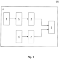
- the only figure 1 shows a schematic of an interaction scheme in an electrically excited synchronous machine 1 according to the invention.
- the synchronous machine 1 has a stator 2 and a rotor 3 .
- the stator 2 is supplied with stator current from a stator source 4 via an inverter 5 .
- the stator current can be represented by a q vector or q component that represents the torque and a d vector or d component that represents the magnetic flux density.
- a rotor current flows in the rotor 3 .
- the rotor 3 is connected to a rotor source 6 via an inductive energy transmitter or a slip ring energy transmitter 7 .
- a voltage is transmitted inductively or directly to the rotor 3 by the energy transmitter 7 and a source-generated component of the rotor current is thereby generated.
- the d component of the stator current additionally generates a stator-generated component of the rotor current in the rotor 3 through inductive coupling or interaction.
- the rotor current in the rotor 3 is therefore made up of the source-generated component and the stator-generated component.
- a method 8 according to the invention the d component of the stator current is adjusted and the stator-generated component of the rotor current is thereby changed. Since the d-part and thus the stator-generated part of the rotor current faster than the source-generated portion is variable, the overall rotor current change can be accelerated. As a result, the control of the synchronous machine and its efficiency can be improved.
Landscapes
- Engineering & Computer Science (AREA)
- Power Engineering (AREA)
- Control Of Ac Motors In General (AREA)
Abstract
Description
- Die Erfindung betrifft ein Verfahren zum Regeln einer elektrisch erregten Synchronmaschine mit einem Stator und einem Rotor nach dem Oberbegriff des Anspruchs 1. Die Erfindung betrifft auch die elektrisch erregte Synchronmaschine.
- In einer elektrisch erregten Synchronmaschine werden der Stator mit einem Stator-Strom und der Rotor mit einem Rotor-Strom bestromt. Die Stromübertragung auf den rotierenden Rotor kann dabei über Schleifringe oder über einen induktiven Energieübertrager erfolgen. Die Induktivität und dadurch die Zeitkonstante des Rotors sind hoch, so dass der Rotor-Strom in dem Rotor sich nur langsam ändern kann. Dieses Phänomen hängt auch mit der zur Verfügung stehenden Spannung im Rotor zusammen, ist jedoch bei der induktiven Stromübertragung durch eine Erhöhung der Spannung nicht zu überwinden.
- Die Aufgabe der Erfindung ist es daher, für ein Verfahren zum Regeln einer elektrisch erregten Synchronmaschine der gattungsgemäßen Art und die elektrisch erregte Synchronmaschine eine verbesserte oder zumindest alternative Ausführungsform anzugeben, bei der die beschriebenen Nachteile überwunden werden.
- Diese Aufgabe wird erfindungsgemäß durch den Gegenstand der unabhängigen Ansprüche gelöst. Vorteilhafte Ausführungsformen sind Gegenstand der abhängigen Ansprüche.
- Die vorliegende Erfindung beruht auf dem allgemeinen Gedanken, eine zwischen einem Stator und einem Rotor einer elektrisch erregten Synchronmaschine bestehende magnetische Kopplung zum Regeln bzw. Anpassen eines im Rotor fließenden Rotor-Stroms zu verwenden.
- Ein Verfahren ist zum Regeln einer elektrisch erregten Synchronmaschine mit einem Stator und einem Rotor vorgesehen. In dem Stator strömt dabei ein Stator-Strom und in dem Rotor strömt ein Rotor-Strom. Der Stator-Strom weist dabei einen auch den Rotor-Strom beeinflussenden d-Anteil und einen überwiegend das Drehmoment beeinflussenden q-Anteil auf. Erfindungsgemäß wird ein quelleerzeugter Anteil des Rotor-Stroms über eine Rotor-Quelle des Rotors erzeugt. Ein statorerzeugter Anteil des Rotor-Stroms wird über eine Anpassung des d-Anteils des Stator-Stroms erzeugt und dadurch wird der Rotor-Strom in dem Rotor geregelt.
- In der erfindungsgemäßen Lösung wird eine induktive Kopplung bzw. Wechselwirkung zwischen dem Stator und dem Rotor der Synchronmaschine genutzt, um den Rotor-Strom zu beeinflussen. Der Stator-Strom kann dabei in einem rotorbezogenen d/q-System durch einen q-Vektor, der überwiegend das Drehmoment abbildet, und einen d-Vektor, der überwiegend die magnetische Flussdichte abbildet, abgebildet werden. Da für die Kopplung bzw. Wechselwirkung die Ausrichtung des Statormagnetfelds zum Rotormagnetfeld entscheidend ist, kann eine Änderung des d-Anteils des Stator-Stroms die Ausrichtung des Statormagnetfelds zu dem Rotormagnetfeld verändern. Dadurch kann der Rotor-Strom in dem Rotor beeinflusst werden. Der d-Anteil des Stator-Stroms wird gelegentlich auch als "Flussrichtung des Rotorflusses" bezeichnet.
- Der Rotor-Strom wird also aus dem quelleerzeugten Anteil und dem statorerzeugten Anteil des Rotor-Stroms zusammengesetzt. Der quelleerzeugte Anteil wird dabei von der Rotor-Quelle und der statorerzeugte Anteil wird durch die Kopplung bzw. Wechselwirkung zwischen dem Statormagnetfeld und dem Rotormagnetfeld erzeugt. Dabei kann der quelleerzeugte Anteil des Rotor-Stroms beispielweise konstant sein bzw. ein konstantes Stromlevel des Rotor-Stroms definieren. Der statorerzeugte Anteil kann dagegen alle dynamischen Änderungen des Rotor-Stroms abbilden. Es versteht sich jedoch, dass diese Aufteilung in der Realität nur teilweise realisierbar ist.
- Der quelleerzeugte Anteil des Rotor-Stroms kann demnach ein konstantes Stromlevel des Rotor-Stroms definieren und der statorerzeugte Anteil dynamische Änderungen des Rotor-Stroms so abbilden, dass der Rotor-Strom schneller als der quelleerzeugte Anteil des Rotor-Stroms verändert wird und dadurch das Regeln der elektrisch erregten Synchronmaschine beschleunigt wird. In anderen Worten kann eine dynamische Änderung des Rotor-Stroms durch die Änderung des statorerzeugten Anteils abgebildet werden, wobei die Änderung des statorerzeugten Anteils schneller als eine Änderung des quelleerzeugten Anteils stattfindet und dadurch die Änderung des Rotor-Stroms und insgesamt das Regeln der elektrischen Maschine beschleunigt wird. Insbesondere kann dadurch das Starten und das Stoppen der elektrischen Maschine durch die Änderung des statorerzeugten Anteils beschleunigt werden.
- Da der Rotor-Strom aus dem quelleerzeugten Anteil und dem statorerzeugten Anteil des Rotor-Stroms zusammengesetzt ist, kann der quelleerzeugte Anteil im Vergleich zu herkömmlichen Lösungen reduziert werden. Entsprechend muss eine geringere Leistung zum Erzeugen des quelleerzeugten Anteiles des Rotor-Stroms an den Rotor übertragen werden. Dadurch kann ein dazu vorgesehener induktiver Energieübertrager oder ein dazu vorgesehener Schleifring-Energieübertrager kleiner dimensioniert werden. Ferner kann die Änderung des Rotor-Stroms zeitlich beschleunigt werden und daher die Regelung der Synchronmaschine verbessert werden. Dadurch kann die Effizienz der Synchronmaschine verbessert werden.
- Der Stator kann vorteilhafterweise über einen Wechselrichter bestromt werden. Dabei kann der Stator mehrere Wicklungen aufweisen, die zu einer dreisträngigen bzw. dreiphasigen Sternpunkt-Schaltung miteinander verschaltet sind. Der Rotor kann über einen induktiven Energieübertrager oder einen Schleifring-Energieübertrager bestromt werden. Dabei wird eine in der stationären Rotor-Quelle bereitgestellte Spannung über den Energieübertrager induktiv oder direkt auf den drehenden Rotor übertragen. Dadurch wird in dem Rotor der quelleerzeugte Anteil des Rotor-Stroms erzeugt. Da der Rotor-Strom neben dem quelleerzeugten Anteil auch den statorerzeugten Anteil aufweist, können der quelleerzeugte Anteil des Rotor-Stroms und demnach die von der Rotor-Quelle bereitgestellte Spannung geringer als herkömmlich sein. Entsprechend muss der Energieübertrager eine geringere Spannung übertragen. In dem Verfahren kann zudem die maximale Energie, die mit dem Energieübertrager übertragbar ist, nahe vollständig statisch definiert werden. Dynamische Effekte können vorteilhafterweise durch den statorerzeugten Anteil des Rotor-Stroms abgebildet sein. Dadurch kann der Energieübertrager insgesamt kompakter dimensioniert werden.
- Vorteilhafterweise kann der quelleerzeugte Anteil des Rotor-Stroms durch eine FEM-Berechnung in einem statischen Betriebspunkt der Synchronmaschine vorbestimmt werden.
- In dem Verfahren kann vorgesehen sein, dass beim Starten der Synchronmaschine zum schnellen Aufbauen eines Drehmoments in dem spannungsfreien und stromfreien Rotor der d-Anteil des Stator-Stroms und dadurch der statorerzeugte Anteil des Rotor-Stroms in dem Rotor erhöht werden. Vor dem Starten der Synchronmaschine ist der Rotor spannungsfrei und stromfrei. Durch die Erhöhung des d-Anteils des Stator-Stroms wird in dem Rotor der statorerzeugte Anteil des Rotor-Stroms erzeugt und dadurch das Drehmoment aufgebaut. Dabei wächst der statorerzeugte Anteil des Rotor-Stroms schneller als der quelleerzeugte Anteil des Rotor-Stroms an. Demnach kann das Drehmoment schneller als allein mit dem quelleerzeugten Anteil des Rotor-Stroms erzeugt werden und die Synchronmaschine kann schneller gestartet werden. Schätzungsweise kann dadurch das Aufbauen des Drehmoments in der Synchronmaschine um einen Faktor zwischen 10 und 100 beschleunigt werden.
- Zusätzlich kann vorgesehen sein, dass der d-Anteil des Stator-Stroms und dadurch der statorerzeugte Anteil des Rotor-Stroms mit dem Anwachsen des quelleerzeugten Anteils des Rotor-Stroms reduziert werden. Sobald also ein ausreichendes Drehmoment über den quelleerzeugten langsamer anwachsenden Anteil produzierbar ist, kann der d-Anteil reduziert werden. Dadurch können die von dem d-Anteil erzeugten Verluste in der Synchronmaschine reduziert werden bzw. nur beim schnellen Starten der Synchronmaschine entstehen.
- Vorteilhafterweise kann die Rotor-Quelle beim Reduzieren des d-Anteils des Stator-Stroms eine Spannung, die eine zum Erzeugen des quelleerzeugten Anteils des Rotor-Stroms notwendige Spannung übersteigt, bereitstellen. Insbesondere kann dadurch eine Drehmomentänderung, die durch eine negative Änderung des d-Anteils des Stator-Stroms bedingt ist, kompensiert werden.
- Um das Verfahren zu optimieren, kann der d-Anteil bezüglich einer Wirkungsgradsteigerung durch ein schnelles Starten der Synchronmaschine und bezüglich einer Wirkungsgradsenkung durch ein Erhöhen des d-Anteils des Stator-Stroms optimiert werden. Mit anderen Worten kann der d-Anteil bezüglich der erzeugten Verluste und bezüglich des schnellen Aufbauens des Drehmoments optimiert werden.
- Beim Stoppen der Synchronmaschine kann zudem zum schnellen Erreichen einer Drehmomentfreiheit in dem Rotor der d-Anteil des Stator-Stroms verändert und dadurch der statorerzeugte Anteil des Rotor-Stroms in dem Rotor reduziert werden. Das Reduzieren des quelleerzeugten Anteils an sich ist zu langsam und kann durch die Anpassung des d-Anteils des Stator-Stroms beschleunigt werden. Hier wird also umgekehrt zum Starten der Synchronmaschine der d-Anteil so angepasst, dass das Drehmoment möglichst schnell auf null gebracht wird. Dadurch kann die funktionale Sicherheit der Synchronmaschine beispielweise bei Fehlerszenarien erhöht werden.
- Bei einer vorteilhaften Ausbildung des Verfahrens kann vorgesehen sein, dass die Synchronmaschine in einem Kraftfahrzeug eingesetzt wird. Dann wird die durch den erhöhten d-Anteil erzeugte Verlustleistung als thermische Energie abgeführt und zum Heizen wenigstens einer weiteren Komponente des Kraftfahrzeugs eingesetzt. Vorzugsweise ist die weitere Komponente des Kraftfahrzeugs eine Batterie und/oder ein Motor und/oder ein Inverter. Dadurch kann die thermische Optimierung des gesamten Kraftfahrzeugs und/oder der Batterie und/oder eines Bordnetzes vorgenommen werden.
- Die Erfindung betrifft auch eine elektrisch erregte Synchronmaschine mit einem Stator und mit einem Rotor. Erfindungsgemäß ist die Synchronmaschine zum Ausführen des oben beschriebenen Verfahrens ausgelegt. Um Wiederholungen zu vermeiden, wird an dieser Stelle auf die obigen Ausführungen verwiesen.
- Weitere wichtige Merkmale und Vorteile der Erfindung ergeben sich aus den Unteransprüchen, aus der Zeichnung und aus der zugehörigen Figurenbeschreibung anhand der Zeichnung.
- Es versteht sich, dass die vorstehend genannten und die nachstehend noch zu erläuternden Merkmale nicht nur in der jeweils angegebenen Kombination, sondern auch in anderen Kombinationen oder in Alleinstellung verwendbar sind, ohne den Rahmen der vorliegenden Erfindung zu verlassen.
- Bevorzugte Ausführungsbeispiele der Erfindung sind in der Zeichnung dargestellt und werden in der nachfolgenden Beschreibung näher erläutert.
- Die einzige
Figur 1 zeigt schematisch ein Wechselwirkungsschema in einer erfindungsgemäßen elektrisch erregten Synchronmaschine 1. Die Synchronmaschine 1 weist dabei einen Stator 2 und einen Rotor 3 auf. Der Stator 2 wird von einer Stator-Quelle 4 über einen Wechselrichter 5 mit Stator-Strom versorgt. In einem rotorbezogenen d/q-System kann der Stator-Strom durch einen das Drehmoment abbildenden q-Vektor bzw. q-Anteil und einen die magnetische Flussdichte abbildenden d-Vektor bzw. d-Anteil dargestellt werden. Eine derartige Darstellung ist dem Fachmann bereits bekannt und wird hier nicht näher erläutert. - In dem Rotor 3 strömt ein Rotor-Strom. Dabei ist der Rotor 3 mit einer Rotor-Quelle 6 über einen induktiven Energieübertrager oder einen Schleifring-Energieübertrager 7 verbunden. Durch den Energieübertrager 7 wird eine Spannung in den Rotor 3 induktiv oder direkt übertragen und dadurch ein quelleerzeugter Anteil des Rotor-Stroms erzeugt. Der d-Anteil des Stator-Stroms erzeugt in dem Rotor 3 durch eine induktive Kopplung bzw. Wechselwirkung zusätzlich einen statorerzeugten Anteil des Rotor-Stroms. Der Rotor-Strom in dem Rotor 3 setzt sich also aus dem quelleerzeugten Anteil und dem statorerzeugten Anteil zusammen.
- In einem erfindungsgemäßen Verfahren 8 wird der d-Anteil des Stator-Stroms angepasst und dadurch der statorerzeugte Anteil des Rotor-Stroms verändert. Da der d-Anteil und dadurch der statorerzeugte Anteil des Rotor-Stroms schneller als der quelleerzeugte Anteil veränderbar ist, kann die Änderung des Rotor-Stroms insgesamt beschleunigt werden. Dadurch können die Regelung der Synchronmaschine und deren Effizienz verbessert werden.
Claims (12)
- Verfahren (8) zum Regeln einer elektrisch erregten Synchronmaschine (1) mit einem Stator (2) und einem Rotor (3),- wobei in dem Stator (2) ein Stator-Strom und in dem Rotor (3) ein Rotor-Strom strömen,- wobei der Stator-Strom einen den Rotor-Strom beeinflussenden d-Anteil und einen das Drehmoment beeinflussenden q-Anteil aufweist,dadurch gekennzeichnet,- dass über eine Rotor-Quelle (6) des Rotors (3) ein quelleerzeugter Anteil des Rotor-Stroms erzeugt wird, und- dass über eine Anpassung des d-Anteils des Stator-Stroms ein statorerzeugter Anteil des Rotor-Stroms erzeugt und dadurch der Rotor-Strom in dem Rotor (3) geregelt wird.
- Verfahren nach Anspruch 1,
dadurch gekennzeichnet,- dass der Stator (2) über einen Wechselrichter (5) bestromt wird, und/oder- dass der Rotor (3) über einen induktiven Energieübertrager (7) oder einen Schleifring-Energieübertrager (7) bestromt wird. - Verfahren nach Anspruch 1 oder 2,
dadurch gekennzeichnet,
dass der quelleerzeugte Anteil des Rotor-Stroms durch eine FEM-Berechnung in einem statischen Betriebspunkt der Synchronmaschine (1) vorbestimmt wird. - Verfahren nach einem der vorangehenden Ansprüche,
dadurch gekennzeichnet,
dass beim Starten der Synchronmaschine (1) zum schnellen Aufbauen eines Drehmoments in dem spannungsfreien und stromfreien Rotor (3) der d-Anteil des Stator-Stroms und dadurch der statorerzeugte Anteil des Rotor-Stroms in dem Rotor (3) erhöht werden. - Verfahren nach Anspruch 4,
dadurch gekennzeichnet,
dass der d-Anteil des Stator-Stroms und dadurch der statorerzeugte Anteil des Rotor-Stroms mit dem Anwachsen des quelleerzeugten Anteils des Rotor-Stroms reduziert werden. - Verfahren nach Anspruch 5,
dadurch gekennzeichnet,
dass die Rotor-Quelle (6) beim Reduzieren des d-Anteils des Stator-Stroms eine Spannung, die eine zum Erzeugen des quelleerzeugten Anteils des Rotor-Stroms notwendige Spannung übersteigt, bereitstellt. - Verfahren nach einem der vorangehenden Ansprüche,
dadurch gekennzeichnet,
dass der d-Anteil des Stator-Stroms bezüglich einer Wirkungsgradsteigerung durch ein schnelles Starten der Synchronmaschine (1) und bezüglich einer Wirkungsgradsenkung durch ein Erhöhen des d-Anteils des Stator-Stroms optimiert wird. - Verfahren nach einem der vorangehenden Ansprüche,
dadurch gekennzeichnet,
dass beim Stoppen der Synchronmaschine (1) zum schnellen Erreichen einer Drehmomentfreiheit in dem Rotor (3) der d-Anteil des Stator-Stroms verändert und dadurch der statorerzeugte Anteil des Rotor-Stroms in dem Rotor (3) reduziert wird. - Verfahren nach einem der vorangehenden Ansprüche,
dadurch gekennzeichnet,
dass die Synchronmaschine (1) in einem Kraftfahrzeug eingesetzt wird und die durch den erhöhten d-Anteil des Stator-Stroms erzeugte Verlustleistung als thermische Energie abgeführt und zum Heizen wenigstens einer weiteren Komponente des Kraftfahrzeugs, vorzugsweise einer Batterie und/oder eines Motors und/oder eines Inverters, eingesetzt wird. - Verfahren nach einem der vorangehenden Ansprüche,
dadurch gekennzeichnet,
dass der quelleerzeugte Anteil des Rotor-Stroms ein konstantes Stromlevel des Rotor-Stroms definieren und der statorerzeugte Anteil dynamische Änderungen des Rotor-Stroms so abbildet, dass der Rotor-Strom insgesamt schneller als der quelleerzeugte Anteil des Rotor-Stroms verändert wird und dadurch das Regeln der elektrisch erregten Synchronmaschine beschleunigt wird. - Verfahren nach einem der vorangehenden Ansprüche,
dadurch gekennzeichnet,
dass eine dynamische Änderung des Rotor-Stroms durch die Änderung des statorerzeugten Anteils abgebildet wird, wobei die Änderung des statorerzeugten Anteils schneller als eine Änderung des quelleerzeugten Anteils stattfindet und dadurch die Änderung des Rotor-Stroms und insgesamt das Regeln der elektrischen Maschine beschleunigt wird. - Elektrisch erregte Synchronmaschine (1) mit einem Stator (2) und mit einem Rotor (3), wobei die Synchronmaschine (1) zum Ausführen des Verfahrens (8) nach einem der vorangehenden Ansprüche ausgelegt ist.
Applications Claiming Priority (1)
| Application Number | Priority Date | Filing Date | Title |
|---|---|---|---|
| DE102021210909.8A DE102021210909B4 (de) | 2021-09-29 | 2021-09-29 | Verfahren zum Regeln einer elektrisch erregten Synchronmaschine |
Publications (1)
| Publication Number | Publication Date |
|---|---|
| EP4160906A1 true EP4160906A1 (de) | 2023-04-05 |
Family
ID=83506342
Family Applications (1)
| Application Number | Title | Priority Date | Filing Date |
|---|---|---|---|
| EP22198017.0A Pending EP4160906A1 (de) | 2021-09-29 | 2022-09-27 | Verfahren zum regeln einer elektrisch erregten synchronmaschine |
Country Status (2)
| Country | Link |
|---|---|
| EP (1) | EP4160906A1 (de) |
| DE (1) | DE102021210909B4 (de) |
Cited By (1)
| Publication number | Priority date | Publication date | Assignee | Title |
|---|---|---|---|---|
| EP4686082A2 (de) | 2024-07-23 | 2026-01-28 | Volkswagen Ag | Verfahren zum steuern einer fremderregten synchronmaschine mit reluktanzanteil für ein zumindest teilweise elektrisch betriebenes kraftfahrzeug mittels einer steuereinrichtung, steuereinrichtung sowie fremderregte synchronmaschine |
Citations (4)
| Publication number | Priority date | Publication date | Assignee | Title |
|---|---|---|---|---|
| US20050007044A1 (en) * | 2003-07-10 | 2005-01-13 | Ming Qiu | Sensorless control method and apparatus for a motor drive system |
| WO2012013447A2 (de) * | 2010-07-28 | 2012-02-02 | Continental Automotive Gmbh | Verfahren und vorrichtung zur regelung fremderregter synchronmaschinen |
| DE102012223441A1 (de) * | 2012-01-05 | 2013-07-11 | GM Global Technology Operations LLC (n. d. Ges. d. Staates Delaware) | Verfahren und System für sensorloses Steuern eines elektrischen Motors |
| DE102019133634A1 (de) * | 2019-12-10 | 2021-06-10 | Bayerische Motoren Werke Aktiengesellschaft | Verfahren zum Betreiben einer elektrischen Maschine eines Kraftfahrzeugs, System sowie Kraftfahrzeug |
Family Cites Families (2)
| Publication number | Priority date | Publication date | Assignee | Title |
|---|---|---|---|---|
| DE102011009935B4 (de) | 2010-03-30 | 2012-10-04 | Sew-Eurodrive Gmbh & Co. Kg | Verfahren zum Ansteuern eines optimalen Betriebspunktes bei einer Synchronmaschine und eine umrichtergespeiste Synchronmaschine |
| DE102010043492A1 (de) | 2010-11-05 | 2012-05-10 | Continental Automotive Gmbh | Verfahren und Vorrichtung zur Regelung fremderregter Synchronmaschinen |
-
2021
- 2021-09-29 DE DE102021210909.8A patent/DE102021210909B4/de active Active
-
2022
- 2022-09-27 EP EP22198017.0A patent/EP4160906A1/de active Pending
Patent Citations (4)
| Publication number | Priority date | Publication date | Assignee | Title |
|---|---|---|---|---|
| US20050007044A1 (en) * | 2003-07-10 | 2005-01-13 | Ming Qiu | Sensorless control method and apparatus for a motor drive system |
| WO2012013447A2 (de) * | 2010-07-28 | 2012-02-02 | Continental Automotive Gmbh | Verfahren und vorrichtung zur regelung fremderregter synchronmaschinen |
| DE102012223441A1 (de) * | 2012-01-05 | 2013-07-11 | GM Global Technology Operations LLC (n. d. Ges. d. Staates Delaware) | Verfahren und System für sensorloses Steuern eines elektrischen Motors |
| DE102019133634A1 (de) * | 2019-12-10 | 2021-06-10 | Bayerische Motoren Werke Aktiengesellschaft | Verfahren zum Betreiben einer elektrischen Maschine eines Kraftfahrzeugs, System sowie Kraftfahrzeug |
Non-Patent Citations (15)
| Title |
|---|
| BASAK SAPTARSHI ET AL: "A brushless generation system for microgrid operation utilizing dual stator induction generator", 2014 IEEE 23RD INTERNATIONAL SYMPOSIUM ON INDUSTRIAL ELECTRONICS (ISIE), IEEE, 1 June 2014 (2014-06-01), pages 302 - 307, XP032624007, DOI: 10.1109/ISIE.2014.6864629 * |
| BHATTACHERJEE HAIMANTI ET AL: "A Brushless Synchronous Generator for Standalone DC Applications", IECON 2019 - 45TH ANNUAL CONFERENCE OF THE IEEE INDUSTRIAL ELECTRONICS SOCIETY, IEEE, vol. 1, 14 October 2019 (2019-10-14), pages 828 - 833, XP033670129, DOI: 10.1109/IECON.2019.8927313 * |
| BHATTACHERJEE HAIMANTI ET AL: "Brushless and Magnetless Synchronous Generator for Standalone DC load with Vienna Rectifier", 2020 IEEE 29TH INTERNATIONAL SYMPOSIUM ON INDUSTRIAL ELECTRONICS (ISIE), IEEE, 17 June 2020 (2020-06-17), pages 83 - 88, XP033800865, DOI: 10.1109/ISIE45063.2020.9152485 * |
| CHOE SEHWA ET AL: "Sensorless Control of Synchronous Machine With an Inverter Integrated Rotor", IEEE TRANSACTIONS ON INDUSTRY APPLICATIONS, IEEE SERVICE CENTER, PISCATAWAY, NJ, US, vol. 50, no. 4, 1 July 2014 (2014-07-01), pages 2584 - 2591, XP011553361, ISSN: 0093-9994, [retrieved on 20140715], DOI: 10.1109/TIA.2013.2294995 * |
| DASH SAGAR KUMAR ET AL: "Speed Control of Brushless Induction Excited Synchronous Motor (BINSYM)", 2020 IEEE INTERNATIONAL CONFERENCE ON POWER ELECTRONICS, DRIVES AND ENERGY SYSTEMS (PEDES), IEEE, 16 December 2020 (2020-12-16), pages 1 - 6, XP033890825, DOI: 10.1109/PEDES49360.2020.9379795 * |
| HWANG DAEYEON ET AL: "Field Current Control Strategy for Wound-Rotor Synchronous Motors Considering Coupled Stator Flux Linkage", IEEE ACCESS, IEEE, USA, vol. 8, 11 June 2020 (2020-06-11), pages 111811 - 111821, XP011795261, DOI: 10.1109/ACCESS.2020.3001866 * |
| KURRAMSETTY VAMSI KRISHNA ET AL: "Influence of WFSM Parameters, Currents and Control Scheme on Its Dynamic Performance During Active Short Circuit Fault in EV", 2021 24TH INTERNATIONAL CONFERENCE ON ELECTRICAL MACHINES AND SYSTEMS (ICEMS), KIEE & EMECS, 31 October 2021 (2021-10-31), pages 564 - 569, XP034050919, DOI: 10.23919/ICEMS52562.2021.9634380 * |
| LIU YE ET AL: "Optimization and Performance Improvement of a Hybrid Excitation Synchronous Machine With Modular Magnetic-Shunting Rotor", IEEE TRANSACTIONS ON INDUSTRIAL ELECTRONICS, IEEE SERVICE CENTER, PISCATAWAY, NJ, USA, vol. 67, no. 6, 15 July 2019 (2019-07-15), pages 4381 - 4390, XP011773071, ISSN: 0278-0046, [retrieved on 20200213], DOI: 10.1109/TIE.2019.2927183 * |
| MADEMLIS GEORGIOS ET AL: "Performance Evaluation of Electrically Excited Synchronous Machine compared to PMSM for High-Power Traction Drives", 2020 INTERNATIONAL CONFERENCE ON ELECTRICAL MACHINES (ICEM), IEEE, vol. 1, 23 August 2020 (2020-08-23), pages 1793 - 1799, XP033868411, DOI: 10.1109/ICEM49940.2020.9270852 * |
| POTHI NATTAPONG ET AL: "Comparison of Flux-Weakening Control Strategies of Novel Hybrid-Excited Doubly Salient Synchronous Machines", IEEE TRANSACTIONS ON INDUSTRY APPLICATIONS, IEEE SERVICE CENTER, PISCATAWAY, NJ, US, vol. 55, no. 4, 1 July 2019 (2019-07-01), pages 3589 - 3597, XP011733150, ISSN: 0093-9994, [retrieved on 20190701], DOI: 10.1109/TIA.2019.2909494 * |
| REIGOSA DAVID ET AL: "Sensorless Control of Wound Rotor Synchronous Motors Based on Rotor High-Frequency Signal Injection", 2020 IEEE ENERGY CONVERSION CONGRESS AND EXPOSITION (ECCE), IEEE, 11 October 2020 (2020-10-11), pages 5111 - 5116, XP033851226, DOI: 10.1109/ECCE44975.2020.9236217 * |
| UZEL D ET AL: "Optimal vector control for wound rotor salient pole synchronous motor up to base speed", POWER ELECTRONICS AND MOTION CONTROL CONFERENCE (EPE/PEMC), 2012 15TH INTERNATIONAL, IEEE, 4 September 2012 (2012-09-04), pages DS2a.12 - 1, XP032311868, ISBN: 978-1-4673-1970-6, DOI: 10.1109/EPEPEMC.2012.6397263 * |
| UZEL DAVID ET AL: "Self-Sensing Control of Wound Rotor Synchronous Motor Drive for Mine Hoist", IEEE TRANSACTIONS ON INDUSTRIAL ELECTRONICS, IEEE SERVICE CENTER, PISCATAWAY, NJ, USA, vol. 65, no. 3, 1 March 2018 (2018-03-01), pages 2009 - 2017, XP011674599, ISSN: 0278-0046, [retrieved on 20171214], DOI: 10.1109/TIE.2017.2740818 * |
| UZEL DAVID ET AL: "Steady state torque optimal operating point control for wound rotor synchronous motors", 2013 INTERNATIONAL CONFERENCE ON APPLIED ELECTRONICS, UNIVERSITY OF WEST BOHEMIA, 6 September 2016 (2016-09-06), pages 277 - 280, XP032971676, ISSN: 1803-7232, ISBN: 978-1-6654-9481-6, [retrieved on 20160926], DOI: 10.1109/AE.2016.7577290 * |
| WENJIA WANG ET AL: "Maximum torque control of hybrid excitation synchronous machine drives based on field current self-optimizing method", IECON 2013 - 39TH ANNUAL CONFERENCE OF THE IEEE INDUSTRIAL ELECTRONICS SOCIETY, IEEE, 10 November 2013 (2013-11-10), pages 2977 - 2982, XP032538774, ISSN: 1553-572X, [retrieved on 20131230], DOI: 10.1109/IECON.2013.6699604 * |
Cited By (1)
| Publication number | Priority date | Publication date | Assignee | Title |
|---|---|---|---|---|
| EP4686082A2 (de) | 2024-07-23 | 2026-01-28 | Volkswagen Ag | Verfahren zum steuern einer fremderregten synchronmaschine mit reluktanzanteil für ein zumindest teilweise elektrisch betriebenes kraftfahrzeug mittels einer steuereinrichtung, steuereinrichtung sowie fremderregte synchronmaschine |
Also Published As
| Publication number | Publication date |
|---|---|
| DE102021210909B4 (de) | 2023-12-14 |
| DE102021210909A1 (de) | 2023-03-30 |
Similar Documents
| Publication | Publication Date | Title |
|---|---|---|
| DE102008034543A1 (de) | Lineargerät für Feldschwächung in einer Maschine mit internen Permanentmagneten | |
| DE3400754A1 (de) | Elektrische rotationsmaschine mit veraenderlicher drehzahl | |
| DE3813735C2 (de) | ||
| EP2761732B1 (de) | System mit einem polumschaltbaren Elektromotor, einem Umrichter und einer Verschalteinheit | |
| DE60118124T2 (de) | Permanentmagnetmotor-generator mit Spamumgsstabilisator | |
| DE2238364C3 (de) | Elektrische Transmissionsanordnung | |
| WO2009040211A2 (de) | Dieselelektrisches fahrzeug | |
| DE102021003612B4 (de) | Verfahren zum Betrieb eines batterieelektrischen Fahrzeugs | |
| EP4160906A1 (de) | Verfahren zum regeln einer elektrisch erregten synchronmaschine | |
| DE2607595A1 (de) | Elektrische stromgeneratoranordnung | |
| DE10202237A1 (de) | Verfahren und Vorrichtung zur Steuerung einer induktions-Maschine | |
| DE2849298A1 (de) | Antriebsanordnung fuer ein zugfahrzeug | |
| DE102023004191A1 (de) | Verfahren zum Beheizen eines Kraftfahrzeuges | |
| EP3686046A1 (de) | Heizbetrieb eines elektrischen antriebssystems eines fahrzeugs | |
| EP0045843A2 (de) | Verfahren zur Nutzung der Abwärmeenergie einer Verbrennungskraftmaschine | |
| DE1281027B (de) | Stromversorgungsanlage fuer ein Wechselspannungsbordnetz auf Schiffen mit Wellengenerator | |
| DE102011003946A1 (de) | Verfahren zum Regeln eines von einer elektrischen Maschine in einem Kraftfahrzeug abgegebenen Ist-Drehmoments auf ein Soll-Drehmoment | |
| DE19830621A1 (de) | Antriebsvorrichtung, insbesondere für Fahrzeuge | |
| EP2683605B1 (de) | Verfahren zum betrieb eines unterseebootes sowie unterseeboot | |
| DE102017130869A1 (de) | Elektrisches Getriebe und Verfahren zum Betreiben eines Elektromotors | |
| DE1538649C3 (de) | Generatoranlage für Wechselstrom konstanter Frequenz bei wechselnder Antriebsdrehzahl | |
| DE69314494T2 (de) | Von einer energiequelle angetriebener rotierender wechselstromgenerator zur erzeugung von elektrischer leistung | |
| DE656278C (de) | Anordnung zur Drehzahlregelung eines elektrischen Schiffsschraubenantriebes | |
| AT106283B (de) | Elektrische Lokomotive. | |
| DE3138894A1 (de) | Vorrichutng zum speisen eines verbrauchers mit einer gesicherten spannung vorgegebener frequenz |
Legal Events
| Date | Code | Title | Description |
|---|---|---|---|
| PUAI | Public reference made under article 153(3) epc to a published international application that has entered the european phase |
Free format text: ORIGINAL CODE: 0009012 |
|
| STAA | Information on the status of an ep patent application or granted ep patent |
Free format text: STATUS: THE APPLICATION HAS BEEN PUBLISHED |
|
| AK | Designated contracting states |
Kind code of ref document: A1 Designated state(s): AL AT BE BG CH CY CZ DE DK EE ES FI FR GB GR HR HU IE IS IT LI LT LU LV MC MK MT NL NO PL PT RO RS SE SI SK SM TR |
|
| STAA | Information on the status of an ep patent application or granted ep patent |
Free format text: STATUS: REQUEST FOR EXAMINATION WAS MADE |
|
| 17P | Request for examination filed |
Effective date: 20230928 |
|
| RBV | Designated contracting states (corrected) |
Designated state(s): AL AT BE BG CH CY CZ DE DK EE ES FI FR GB GR HR HU IE IS IT LI LT LU LV MC MK MT NL NO PL PT RO RS SE SI SK SM TR |
|
| STAA | Information on the status of an ep patent application or granted ep patent |
Free format text: STATUS: EXAMINATION IS IN PROGRESS |
|
| 17Q | First examination report despatched |
Effective date: 20241025 |