EP4160898A1 - Inverter having optimized electromagnetic behavior - Google Patents
Inverter having optimized electromagnetic behavior Download PDFInfo
- Publication number
- EP4160898A1 EP4160898A1 EP22198223.4A EP22198223A EP4160898A1 EP 4160898 A1 EP4160898 A1 EP 4160898A1 EP 22198223 A EP22198223 A EP 22198223A EP 4160898 A1 EP4160898 A1 EP 4160898A1
- Authority
- EP
- European Patent Office
- Prior art keywords
- inverter
- busbar
- bridges
- positive
- negative
- Prior art date
- Legal status (The legal status is an assumption and is not a legal conclusion. Google has not performed a legal analysis and makes no representation as to the accuracy of the status listed.)
- Pending
Links
- 239000003990 capacitor Substances 0.000 claims abstract description 33
- 239000004065 semiconductor Substances 0.000 claims abstract description 13
- 238000001816 cooling Methods 0.000 claims abstract description 12
- 238000005538 encapsulation Methods 0.000 claims description 12
- 238000001746 injection moulding Methods 0.000 claims description 7
- 239000012778 molding material Substances 0.000 claims description 7
- 238000005476 soldering Methods 0.000 claims description 4
- 230000005540 biological transmission Effects 0.000 claims 1
- 238000007599 discharging Methods 0.000 abstract 1
- 239000011888 foil Substances 0.000 description 7
- 238000013461 design Methods 0.000 description 4
- 230000010354 integration Effects 0.000 description 4
- 230000008878 coupling Effects 0.000 description 3
- 238000010168 coupling process Methods 0.000 description 3
- 238000005859 coupling reaction Methods 0.000 description 3
- 238000002955 isolation Methods 0.000 description 2
- 239000002184 metal Substances 0.000 description 2
- 238000000034 method Methods 0.000 description 2
- 238000004804 winding Methods 0.000 description 2
- 230000004888 barrier function Effects 0.000 description 1
- 238000009529 body temperature measurement Methods 0.000 description 1
- 238000007796 conventional method Methods 0.000 description 1
- 230000001419 dependent effect Effects 0.000 description 1
- 238000011161 development Methods 0.000 description 1
- 230000018109 developmental process Effects 0.000 description 1
- 239000012777 electrically insulating material Substances 0.000 description 1
- 230000017525 heat dissipation Effects 0.000 description 1
- 230000001771 impaired effect Effects 0.000 description 1
- 238000009413 insulation Methods 0.000 description 1
- 239000007788 liquid Substances 0.000 description 1
- 238000012545 processing Methods 0.000 description 1
- 238000000926 separation method Methods 0.000 description 1
- 238000005245 sintering Methods 0.000 description 1
- 239000000758 substrate Substances 0.000 description 1
- 238000003466 welding Methods 0.000 description 1
Images


Classifications
-
- H—ELECTRICITY
- H02—GENERATION; CONVERSION OR DISTRIBUTION OF ELECTRIC POWER
- H02M—APPARATUS FOR CONVERSION BETWEEN AC AND AC, BETWEEN AC AND DC, OR BETWEEN DC AND DC, AND FOR USE WITH MAINS OR SIMILAR POWER SUPPLY SYSTEMS; CONVERSION OF DC OR AC INPUT POWER INTO SURGE OUTPUT POWER; CONTROL OR REGULATION THEREOF
- H02M7/00—Conversion of ac power input into dc power output; Conversion of dc power input into ac power output
- H02M7/42—Conversion of dc power input into ac power output without possibility of reversal
- H02M7/44—Conversion of dc power input into ac power output without possibility of reversal by static converters
- H02M7/48—Conversion of dc power input into ac power output without possibility of reversal by static converters using discharge tubes with control electrode or semiconductor devices with control electrode
- H02M7/53—Conversion of dc power input into ac power output without possibility of reversal by static converters using discharge tubes with control electrode or semiconductor devices with control electrode using devices of a triode or transistor type requiring continuous application of a control signal
- H02M7/537—Conversion of dc power input into ac power output without possibility of reversal by static converters using discharge tubes with control electrode or semiconductor devices with control electrode using devices of a triode or transistor type requiring continuous application of a control signal using semiconductor devices only, e.g. single switched pulse inverters
- H02M7/5387—Conversion of dc power input into ac power output without possibility of reversal by static converters using discharge tubes with control electrode or semiconductor devices with control electrode using devices of a triode or transistor type requiring continuous application of a control signal using semiconductor devices only, e.g. single switched pulse inverters in a bridge configuration
-
- B—PERFORMING OPERATIONS; TRANSPORTING
- B60—VEHICLES IN GENERAL
- B60K—ARRANGEMENT OR MOUNTING OF PROPULSION UNITS OR OF TRANSMISSIONS IN VEHICLES; ARRANGEMENT OR MOUNTING OF PLURAL DIVERSE PRIME-MOVERS IN VEHICLES; AUXILIARY DRIVES FOR VEHICLES; INSTRUMENTATION OR DASHBOARDS FOR VEHICLES; ARRANGEMENTS IN CONNECTION WITH COOLING, AIR INTAKE, GAS EXHAUST OR FUEL SUPPLY OF PROPULSION UNITS IN VEHICLES
- B60K1/00—Arrangement or mounting of electrical propulsion units
-
- H—ELECTRICITY
- H02—GENERATION; CONVERSION OR DISTRIBUTION OF ELECTRIC POWER
- H02M—APPARATUS FOR CONVERSION BETWEEN AC AND AC, BETWEEN AC AND DC, OR BETWEEN DC AND DC, AND FOR USE WITH MAINS OR SIMILAR POWER SUPPLY SYSTEMS; CONVERSION OF DC OR AC INPUT POWER INTO SURGE OUTPUT POWER; CONTROL OR REGULATION THEREOF
- H02M1/00—Details of apparatus for conversion
- H02M1/44—Circuits or arrangements for compensating for electromagnetic interference in converters or inverters
-
- H—ELECTRICITY
- H02—GENERATION; CONVERSION OR DISTRIBUTION OF ELECTRIC POWER
- H02M—APPARATUS FOR CONVERSION BETWEEN AC AND AC, BETWEEN AC AND DC, OR BETWEEN DC AND DC, AND FOR USE WITH MAINS OR SIMILAR POWER SUPPLY SYSTEMS; CONVERSION OF DC OR AC INPUT POWER INTO SURGE OUTPUT POWER; CONTROL OR REGULATION THEREOF
- H02M7/00—Conversion of ac power input into dc power output; Conversion of dc power input into ac power output
- H02M7/003—Constructional details, e.g. physical layout, assembly, wiring or busbar connections
-
- H—ELECTRICITY
- H05—ELECTRIC TECHNIQUES NOT OTHERWISE PROVIDED FOR
- H05K—PRINTED CIRCUITS; CASINGS OR CONSTRUCTIONAL DETAILS OF ELECTRIC APPARATUS; MANUFACTURE OF ASSEMBLAGES OF ELECTRICAL COMPONENTS
- H05K7/00—Constructional details common to different types of electric apparatus
- H05K7/14—Mounting supporting structure in casing or on frame or rack
- H05K7/1422—Printed circuit boards receptacles, e.g. stacked structures, electronic circuit modules or box like frames
- H05K7/1427—Housings
- H05K7/1432—Housings specially adapted for power drive units or power converters
- H05K7/14329—Housings specially adapted for power drive units or power converters specially adapted for the configuration of power bus bars
-
- B—PERFORMING OPERATIONS; TRANSPORTING
- B60—VEHICLES IN GENERAL
- B60K—ARRANGEMENT OR MOUNTING OF PROPULSION UNITS OR OF TRANSMISSIONS IN VEHICLES; ARRANGEMENT OR MOUNTING OF PLURAL DIVERSE PRIME-MOVERS IN VEHICLES; AUXILIARY DRIVES FOR VEHICLES; INSTRUMENTATION OR DASHBOARDS FOR VEHICLES; ARRANGEMENTS IN CONNECTION WITH COOLING, AIR INTAKE, GAS EXHAUST OR FUEL SUPPLY OF PROPULSION UNITS IN VEHICLES
- B60K1/00—Arrangement or mounting of electrical propulsion units
- B60K2001/001—Arrangement or mounting of electrical propulsion units one motor mounted on a propulsion axle for rotating right and left wheels of this axle
-
- H—ELECTRICITY
- H01—ELECTRIC ELEMENTS
- H01L—SEMICONDUCTOR DEVICES NOT COVERED BY CLASS H10
- H01L25/00—Assemblies consisting of a plurality of individual semiconductor or other solid state devices ; Multistep manufacturing processes thereof
- H01L25/03—Assemblies consisting of a plurality of individual semiconductor or other solid state devices ; Multistep manufacturing processes thereof all the devices being of a type provided for in the same subgroup of groups H01L27/00 - H01L33/00, or in a single subclass of H10K, H10N, e.g. assemblies of rectifier diodes
- H01L25/04—Assemblies consisting of a plurality of individual semiconductor or other solid state devices ; Multistep manufacturing processes thereof all the devices being of a type provided for in the same subgroup of groups H01L27/00 - H01L33/00, or in a single subclass of H10K, H10N, e.g. assemblies of rectifier diodes the devices not having separate containers
- H01L25/07—Assemblies consisting of a plurality of individual semiconductor or other solid state devices ; Multistep manufacturing processes thereof all the devices being of a type provided for in the same subgroup of groups H01L27/00 - H01L33/00, or in a single subclass of H10K, H10N, e.g. assemblies of rectifier diodes the devices not having separate containers the devices being of a type provided for in group H01L29/00
- H01L25/072—Assemblies consisting of a plurality of individual semiconductor or other solid state devices ; Multistep manufacturing processes thereof all the devices being of a type provided for in the same subgroup of groups H01L27/00 - H01L33/00, or in a single subclass of H10K, H10N, e.g. assemblies of rectifier diodes the devices not having separate containers the devices being of a type provided for in group H01L29/00 the devices being arranged next to each other
-
- H—ELECTRICITY
- H01—ELECTRIC ELEMENTS
- H01R—ELECTRICALLY-CONDUCTIVE CONNECTIONS; STRUCTURAL ASSOCIATIONS OF A PLURALITY OF MUTUALLY-INSULATED ELECTRICAL CONNECTING ELEMENTS; COUPLING DEVICES; CURRENT COLLECTORS
- H01R12/00—Structural associations of a plurality of mutually-insulated electrical connecting elements, specially adapted for printed circuits, e.g. printed circuit boards [PCB], flat or ribbon cables, or like generally planar structures, e.g. terminal strips, terminal blocks; Coupling devices specially adapted for printed circuits, flat or ribbon cables, or like generally planar structures; Terminals specially adapted for contact with, or insertion into, printed circuits, flat or ribbon cables, or like generally planar structures
- H01R12/50—Fixed connections
- H01R12/51—Fixed connections for rigid printed circuits or like structures
- H01R12/55—Fixed connections for rigid printed circuits or like structures characterised by the terminals
- H01R12/58—Fixed connections for rigid printed circuits or like structures characterised by the terminals terminals for insertion into holes
- H01R12/585—Terminals having a press fit or a compliant portion and a shank passing through a hole in the printed circuit board
Definitions
- the invention relates to an inverter for energizing an electric drive of an electric vehicle or a hybrid vehicle and a corresponding vehicle with such an inverter.
- Purely electric vehicles and hybrid vehicles are known in the prior art, which are driven exclusively or in support of one or more electric machines as drive units.
- the electric vehicles and hybrid vehicles include electric energy stores, in particular rechargeable electric batteries. These batteries are designed as DC voltage sources, but the electrical machines usually require an AC voltage. Therefore, power electronics with a so-called inverter are usually connected between a battery and an electric machine of an electric vehicle or a hybrid vehicle.
- Such inverters typically include semiconductor switching elements typically formed of transistors. It is known to provide the semiconductor switching elements in different degrees of integration, namely either as discrete individual switches with a low degree of integration but high scalability, as power modules with a high degree of integration but low scalability, and as half-bridges, which in terms of degree of integration and scalability between individual switches and half-bridges or power electronics modules.
- the inverters known from the prior art have a high leakage inductance due to their design.
- the functionality of the known inverters is impaired because the leakage inductance is coupled to the switching speed of the semiconductor switching elements and thereby causes excessive voltage increases.
- the heat that is generated during operation of the inverter can only be dissipated insufficiently, which impairs the functionality of the inverter.
- the invention relates to an inverter for operating an electric axle drive in an electric vehicle and/or a hybrid vehicle.
- the inverter includes a DC input for connecting a DC voltage source.
- the DC voltage source is a battery, for example, in particular a high-voltage battery (HV battery), which provides a DC voltage of 400V or 800V. This DC voltage is applied between a positive pole and a negative pole of the DC input.
- the inverter includes an intermediate circuit capacitor, which has a plurality of input contacts for injecting a DC current generated by the DC voltage source.
- the input contacts are attached to a capacitor housing of the intermediate circuit capacitor.
- the input contacts include both positive and negative input contacts.
- the positive input contacts are connected to the positive pole of the DC input and thus to a positive electrode of the DC voltage source.
- the negative input contacts are connected to the negative pole of the DC input and thus to a negative electrode of the DC voltage source.
- the inverter also includes a plurality of half-bridges each having a plurality of semiconductor switching elements for converting the DC current to an AC current having a plurality of phase currents.
- Each half-bridge is assigned to a phase or a phase current of the AC current.
- the half ridges extend along a longitudinal direction from the DC input to the AC output.
- the individual half-bridges are arranged in a row along a transverse direction perpendicular to the longitudinal direction.
- Each half-bridge can preferably comprise a single half-bridge module or multiple half-bridge modules.
- the half-bridge module in the sense of the present
- the invention is a modular bridge circuit that includes a module high side and a module low side.
- the module high side and the module low side each include one or more semiconductor switching elements connected in parallel.
- the module highsides of these half-bridge modules are connected in parallel to one another and form a common highside of the entire half-bridge, with the module lowsides of these half-bridge modules also being connected in parallel to one another and form a common lowside of the entire half-bridge. This means that, depending on the desired vehicle performance, the amount of current that can be carried by the half-bridges can be scaled up or down as desired by a suitable choice of the number of half-bridge modules.
- the inverter further includes a DC bus bar arrangement for feeding the DC current into the half-bridges.
- the DC bus bar assembly has a positive DC bus bar and a negative DC bus bar.
- the DC current flows from the input contacts of the intermediate circuit capacitor via the latter to the positive and negative DC power rails. There the DC current is fed into the respective half-bridges, preferably into the individual half-bridge modules.
- the AC busbar arrangement comprises a plurality of AC busbars, each of which has a plurality of input contacts and one output contact.
- the input contacts are connected to AC power terminals of the half-bridges, with the output contact being connected to the electric motor of the electric axle drive, in particular to its winding.
- the output contacts of the multiple phases are part of the AC output of the inverter.
- the inverter also includes a cooler for cooling the half-bridges.
- the cooler is preferably on the underside the half-bridges, in particular connected to a metal layer of a substrate of the respective half-bridge modules.
- the positive and/or negative DC busbar extends across the row of half-bridges. This means that the width of the positive and/or negative DC busbars comes close to the width of the row of half-bridges. This increases the area of the DC bus bars, so that the current density of the DC current to be carried by the DC bus bars is reduced. This reduces the heat generated by the current into the half-bridges. In addition, a current flow that is symmetrical with respect to the longitudinal direction is made possible, and the leakage inductance of the inverter is reduced and the electromagnetic behavior (EMC) of the inverter is improved. In addition, the large-area DC busbars allow the inverter to have a flat design, which means a more compact design for the inverter.
- the positive DC busbar and the negative DC busbar have several busbar branches on the output side for connection to a DC power input of the half-bridge modules, each busbar branch being assigned to one of the half-bridge modules.
- each busbar branch being assigned to one of the half-bridge modules.
- two busbar branches are therefore assigned to this half-bridge, with the inverter having a total of six busbar branches in the case of a three-phase AC current. This measure facilitates distributed contacting between the DC busbar arrangement and the half bridges.
- the inverter can also have more or fewer half-bridge modules or busbar branches.
- the positive DC busbar and/or the negative DC busbar is encapsulated on the outside with a current-insulating injection molding material.
- the encapsulation of the DC busbar arrangement serves both to increase the mechanical stability and to increase the clearance and creepage distances between the positive and negative DC busbars in order to ensure safe electrical isolation between them.
- the encapsulation of the positive DC busbar and/or the negative DC busbar comprises a plurality of attachment points, each for a fastener for fixing the encapsulation to an inverter housing, wherein the number of attachment points can correspond to the number of half-bridges, with a relative position between the attachment point and the associated half-bridge is the same for all half-bridges.
- the attachment points are designed, for example, as openings, in particular as through-openings, which preferably extend through the encapsulation, the positive and the negative DC busbar.
- the fastener is preferably a metal fastener such as a screw.
- the encapsulation of the positive DC busbar and/or the negative DC busbar has a plurality of openings for passing through signal connections of the half-bridges. This measure facilitates the contacting of the signal connections to a printed circuit board of the inverter, which is to be fitted on top of the encapsulation.
- the signal connections can be positioned over the support frame.
- all signal connections of the half-bridges are connected to the printed circuit board by means of soldering.
- all signal connections can be connected to the printed circuit board during assembly using the same connection method, namely soldering. This eliminates additional connection steps that would be required due to the use of several different connection methods and thus reduces the assembly effort of the inverter.
- press-fit pins can be used as signal connectors.
- a support frame for accommodating the half-bridge modules is arranged between an inverter housing and a circuit board, with a plurality of signal connections of the half-bridges vertically through the Support frames are passed in the direction of a printed circuit board.
- the carrier frame increases the mechanical stability of the signal connections and protects them from breakage when connecting to the printed circuit board.
- the support frame serves to position the signal connections.
- the carrier frame enables a form-fit or a force-fit connection between various components within the inverter, which increases the robustness of the inverter.
- the support frame is used to maintain clearance and creepage distances.
- a temperature sensor is arranged between a printed circuit board and the cooler in such a way that the temperature sensor is fixed on the underside by means of a thermally conductive layer on the cooler or the half-bridge modules, with at least one signal line of the temperature sensor extending through the carrier frame and into the printed circuit board.
- the temperature sensor is thermally better coupled to the cooler.
- the support frame stabilizes the position of the temperature sensor and increases the reliability of the temperature measurement.
- a current-insulating heat-conducting foil is arranged between an inverter housing and the DC input, the DC busbar arrangement and/or the AC busbar arrangement.
- the thermally conductive foil improves the thermal coupling between the inverter housing on the one hand and the DC input, the DC busbar arrangement and/or the AC busbar arrangement on the other hand. This achieves more efficient heat dissipation from the current-carrying components of the inverter.
- the heat-conducting foil also serves to maintain the air and creepage distances and thus to isolate the potential between the components of the inverter to which current is applied.
- the invention also relates to an electric axle drive with such an inverter and a vehicle with such an electric axle drive. This also results in the advantages already described in connection with the inverter according to the invention for the inverter according to the invention and the vehicle according to the invention.
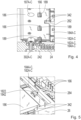
- the inverter 10 includes a DC input 12, an intermediate circuit capacitor 14, a plurality of half-bridges 16A-C, a DC busbar arrangement, an AC output 22, a cooler 24, a printed circuit board 28 and an inverter housing 30.
- the inverter 10 has other components , which are detailed below.
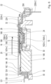
- the DC input 12 is here and also in 2 shown in more detail in a side sectional view.
- the DC input 12 includes a positive input connection 121 and a negative input connection 123, the input connections 121, 123 being designed for connection to a DC voltage source, preferably a battery, in particular a high-voltage (HV) battery.
- the DC input 12 also includes a plurality of positive input contacts 122 and a plurality of negative input contacts 124.
- the positive input contacts 122 are embodied here as output-side current contacts of the positive input connection 121, with the negative input contacts 124 being embodied as output-side current contacts of the negative input connection 123.
- the input contacts 122, 124 are encapsulated with an electrically insulating injection molding material.
- the encapsulation 126 serves at the same time as a frame for the input contacts 122, 124 and is applied to the inverter housing 30 on the underside by means of a current-insulating thermally conductive film 32 .
- the intermediate circuit capacitor 14 includes a capacitor housing 146, on whose first edge facing the DC input 12 a plurality of positive and negative capacitor input contacts 142, 144 are arranged.
- the positive capacitor input contacts 142 are electrically connected to the positive input contacts 122 and the negative capacitor input contacts 144 are electrically connected to the negative input contacts 124 .
- the input contacts 122, 124 and the capacitor input contacts 142, 144 are arranged on the capacitor housing 146 in such a way that the positive capacitor input contacts 142 and the negative capacitor input contacts 144 are lined up alternately, as in FIG 1 shown.
- the capacitor case 146 is box-shaped and extends in a longitudinal direction between the DC input and the AC output and in a transverse direction perpendicular thereto.
- the DC bus bar assembly is attached to a second edge opposite the capacitor input contacts 142,144.
- the DC bus assembly connects the link capacitor 14 to the half-bridges 16A-C.
- the DC busbar arrangement has a positive DC busbar 18 and a negative DC busbar 20 which extend across the width of the capacitor housing 146 .
- the intermediate circuit capacitor 14 has a transverse contact 148 on the output side (see FIG 1 , 3 and 6 ) to which the positive DC bus bar 18 is electrically connected, as shown in side view in FIG 6 shown.
- the negative DC busbar 20, on the other hand, is integrated in the intermediate circuit capacitor 14 and preferably extends, as shown in FIG 6 shown schematically, from the power electronics 16 to the intermediate circuit capacitor 14 inside.
- the DC busbars 18, 20 have a plurality of positive or negative busbar branches 182A-C, 184A-C, 202A-C, 204A-C, which are each connected to a half-bridge module 162A-C, 164A-C of the half-bridges 16A-C are.
- the half-bridge modules 162A-C, 164A-C each include a module high side and a module low side, the module high side and the module low side each including one or more semiconductor switching elements connected in parallel.
- the module high-sides of the half-bridge modules 162A-C, 164A-C are connected in parallel with one another to form a high-side of the half-bridge 16A-C.
- each half-bridge 16A-C the module lowsides of the half-bridge modules 162A-C, 164A-C are connected in parallel with one another to form a lowside of the half-bridge 16A-C.
- each half-bridge 16A-C comprises a first half-bridge module 162A-C and a second half-bridge module 164A-C.
- Each half-bridge module 162A-C, 164A-C has a positive DC power connection and a negative DC power connection.
- a positive busbar junction 182A-C, 184A-C makes electrical contact with the positive DC power connection.
- a negative busbar junction 202A-C, 204A-C is electrically connected to the negative DC power connection.
- the electrical contact is made as in 6 shown schematically, on top of the respective half-bridge modules 162A-C, 164A-C, what is simpler than conventional methods of contacting and enables the inverter 10 to have a compact design.
- the DC busbar arrangement can also be encapsulated using an electrically insulating injection molding material.
- the encapsulation 186 of the positive DC busbar 18 takes place on both sides, ie on the top and bottom.
- An insulating film is provided between the encapsulation 186 of the positive DC busbar 18 and the negative DC busbar 20 and preferably extends only partially over the negative DC busbar 18 .
- the DC busbars 18, 20 each have an intermediate section that runs along the width, in which several fastening points 187A-C, 206A -C for attaching multiple fasteners 302A-C (see 4 ) for the purpose of fixing the DC bus bar assembly to the inverter housing 30 are formed.
- the fastening points 187A-C, 206A-C are preferably designed as screw holes, with the fastening means 302A-C preferably being screws which pass through the positive DC busbar 18, the negative DC busbar 20 and the overmolding 186 bis on the top side of the DC busbar arrangement extends into the inverter housing 30. This enables the DC busbar arrangement to be attached in a particularly stable manner.
- a plurality of openings 189, 208 are formed in the intermediate portion of the positive and negative DC bus bars 18, 20 through which a plurality of signal terminals 166 of the half-bridges 16A-C pass upwardly.
- the signal connections 166 extend through the printed circuit board 28 in order to transmit control signals between it and the half-bridges 16A-C, in particular the control connections (gate electrodes) of the semiconductor switching elements.
- a support frame 26 is, as in 1 and 6 shown, is arranged between the half-bridges 16A-C on the one hand and the inverter housing 30 on the other hand.
- the signal terminals 166 extend upwardly from the semiconductor switching elements through a plurality of signal towers of the support frame 26 and the openings 189, 208 of the DC bus bars 18, 20 to be received in the circuit board 28 (see Fig 6 ).
- the support frame 26 is on the underside the cooler 24, supported on the other hand on the inverter housing 30.
- the cooler 24 can have a cooling structure for directly cooled liquid cooling with a plurality of fins (pin-fin structure) which extend downwards, starting from a cooling plate.
- This cooling structure can be geometrically designed for various boundary conditions, so that an optimal ratio between the flow energy used and the heat output to be dissipated is established. This increases the cooling surface and increases the cooling capacity.
- the half-bridge modules 162A-C, 164A-C are externally overmolded with an electrically insulating injection molding material to protect the semiconductor switching elements from the environment. Only the power connections (not shown), the signal connections 166 and a bottom surface connecting to the heatsink 24 are exposed from the injection molding material.
- the half-bridge modules 162A-C, 164A-C are each connected to the cooling plate by means of sintering or soldering.
- the support frame 26 is used to guide the signal connections 166, to accommodate a temperature sensor 34 (described in more detail below) and to maintain the air and creepage distances.
- An insulating foil 242 is arranged between the half-bridge modules 182A-C, 184A-C and the cooler 24 in order to maintain the air and creepage distances between the power connections of the half-bridge modules 162AC, 164A-C on the one hand and the cooling plate on the other hand.
- the AC outlet 22 (or AC bus bar assembly) includes a plurality of AC bus bars 222A-C, a plurality of AC output contacts 226A-C connected to the AC bus bars 222A-C, and an overmold 224 formed by overmolding the AC bus bars 222A-C with an electrically insulating injection molding material.
- the overmold 224 is on top of the AC bus bars 222A-C.
- a current-insulating heat-conducting foil 32 is arranged underneath the AC bus bars 222A-C for the purpose of increased thermal coupling to the inverter housing 30 .
- the AC busbars 222A-C are partially encapsulated with the current-isolating heat-conducting foil 32 and partially with an electrically insulating material. This measure ensures a local thermal coupling there, which is limited to an area where underside cooling of the AC bus bars 222A-C is needed. This avoids that the cost-intensive current-insulating heat-conducting foil 32 is used unnecessarily.
- the AC power rails 222A-C each extend horizontally between an AC power terminal of the half-bridge modules 162A-C, 164A-C and one of the AC output contacts 226A-C.
- the half-bridge modules 162A-C, 164A-C each have a plurality (two in this example) AC power terminals that are each electrically connected to one of the AC power rails 222A-C.
- the AC output contacts 226A-C are oriented vertically and project beyond an end portion 304 of the inverter housing 30 for connection to windings of an electric final drive electric machine.
- a current sensor 36 is electrically connected to the printed circuit board 28 on the underside, preferably soldered.
- a recess 228 is formed in the overmold 224 of the AC bus bars 222A-C.
- the cutout 228 reduces the distance between the current sensor 36 and the AC bus bars 222A-C.
- a bottom layer of the recess 228 serves for potential isolation between the current sensor 36 and the AC bus bars 222A-C.
- the current sensor 36 is used to detect the respective AC phase currents.
- the current sensor 36 typically includes a plurality of signal lines (not shown here) that are electrically connected or soldered to the circuit board 28 in order to transmit the sensed current levels to an internal or external processing unit, such as a vehicle ECU (not shown here).
- a temperature sensor 34 is, as in figure 8 shown disposed in a space between the support frame 26 and the radiator 24.
- the temperature sensor 34 comprises a sensor body 344 and two signal lines 342, which first extend horizontally and then vertically upwards from both ends of the sensor body 344.
- the signal lines 342 are routed through the carrier frame 26 and the circuit board 28 .
- a thermally conductive layer 346 is attached between the sensor body 344 and the cooler 24 .
Abstract
Die Erfindung betrifft einen Inverter (10) zum Betreiben eines elektrischen Antriebs in einem Elektrofahrzeug und/oder einem Hybridfahrzeug, umfassend einen DC-Eingang (12) zum Anschließen einer DC-Spannungsquelle, einen Zwischenkreiskondensator (14), der mehrere Eingangskontakte (142) zum Injizieren eines mittels der DC-Spannungsquelle erzeugten DC-Stroms aufweist, wobei die Eingangskontakte (142) an einem Kondensatorgehäuse (146) des Zwischenkreiskondensators (14) angebracht sind, mehrere Halbbrücken (16A-C), die jeweils mehrere Halbleiterschaltelemente zum Umwandeln des DC-Stroms in einen AC-Strom mit mehreren Phasenströmen aufweisen, wobei die Halbbrücken (16A-C) in einer Querrichtung des Inverters (10) in einer Reihe angeordnet sind, eine DC-Stromschienenanordnung zum Einspeisen des DC-Stroms in die Halbbrücken, die eine positive DC-Stromschiene (18) und eine negative DC-Stromschiene (20) aufweist, wobei sich die positive und/oder negative DC-Stromschiene (18, 20) in der Querrichtung des Inverters (10) über die Reihe der Halbbrücken (16A-C) erstreckt, sodass die Breite der positiven und/oder negativen DC-Stromschiene (18, 20) an die Breite der Reihe der Halbbrücken (16A-C) heranreicht, eine AC-Stromschienenanordnung (22) zum Abgeben des AC-Stroms in den elektrischen Antrieb, einen Kühler (24) zum Abkühlen der Halbbrücken (16A-C).The invention relates to an inverter (10) for operating an electric drive in an electric vehicle and/or a hybrid vehicle, comprising a DC input (12) for connecting a DC voltage source, an intermediate circuit capacitor (14) which has a plurality of input contacts (142) for Injecting a DC current generated by the DC voltage source, the input contacts (142) being attached to a capacitor housing (146) of the intermediate circuit capacitor (14), a plurality of half-bridges (16A-C) each having a plurality of semiconductor switching elements for converting the DC current into an AC current with multiple phase currents, the half-bridges (16A-C) being arranged in a row in a transverse direction of the inverter (10), a DC bus bar arrangement for injecting the DC current into the half-bridges which have a positive DC bus bar (18) and a negative DC bus bar (20), the positive and/or negative DC bus bar (18, 20) extending in the transverse direction of the inverter (10) across the series of half bridges (16A-C ) extends so that the width of the positive and/or negative DC busbar (18, 20) reaches the width of the row of half-bridges (16A-C), an AC busbar arrangement (22) for discharging the AC current into the electrical drive, a cooler (24) for cooling the half-bridges (16A-C).
Description
Die Erfindung betrifft einen Inverter zum Bestromen eines elektrischen Antriebs eines Elektrofahrzeugs oder eines Hybridfahrzeugs sowie ein entsprechendes Fahrzeug mit einem solchen Inverter.The invention relates to an inverter for energizing an electric drive of an electric vehicle or a hybrid vehicle and a corresponding vehicle with such an inverter.
Im Stand der Technik sind reine Elektrofahrzeuge sowie Hybridfahrzeuge bekannt, welche ausschließlich bzw. unterstützend von einer oder mehreren elektrischen Maschinen als Antriebsaggregate angetrieben werden. Um die elektrischen Maschinen solcher Elektrofahrzeuge bzw. Hybridfahrzeuge mit elektrischer Energie zu versorgen, umfassen die Elektrofahrzeuge und Hybridfahrzeuge elektrische Energiespeicher, insbesondere wiederaufladbare elektrische Batterien. Diese Batterien sind dabei als Gleichspannungsquellen ausgebildet, die elektrischen Maschinen benötigen in der Regel jedoch eine Wechselspannung. Daher wird zwischen einer Batterie und einer elektrischen Maschine eines Elektrofahrzeugs oder eines Hybridfahrzeugs üblicherweise eine Leistungselektronik mit einem sog. Inverter geschaltet.Purely electric vehicles and hybrid vehicles are known in the prior art, which are driven exclusively or in support of one or more electric machines as drive units. In order to supply the electric machines of such electric vehicles or hybrid vehicles with electric energy, the electric vehicles and hybrid vehicles include electric energy stores, in particular rechargeable electric batteries. These batteries are designed as DC voltage sources, but the electrical machines usually require an AC voltage. Therefore, power electronics with a so-called inverter are usually connected between a battery and an electric machine of an electric vehicle or a hybrid vehicle.
Derartige Inverter umfassen üblicherweise Halbleiterschaltelemente, die typischerweise aus Transistoren gebildet sind. Dabei ist es bekannt, die Halbleiterschaltelemente in unterschiedlichen Integrationsgraden bereitzustellen, nämlich entweder als diskrete Einzelschalter mit einem geringen Integrationsgrad, jedoch hoher Skalierbarkeit, als Leistungsmodule mit einem hohen Integrationsgrad, jedoch geringer Skalierbarkeit, sowie als Halbbrücken, die hinsichtlich Integrationsgrad und Skalierbarkeit zwischen Einzelschaltern und Halbbrücken bzw. Leistungselektronikmodulen rangieren.Such inverters typically include semiconductor switching elements typically formed of transistors. It is known to provide the semiconductor switching elements in different degrees of integration, namely either as discrete individual switches with a low degree of integration but high scalability, as power modules with a high degree of integration but low scalability, and as half-bridges, which in terms of degree of integration and scalability between individual switches and half-bridges or power electronics modules.
Die aus dem Stand der Technik bekannten Inverter weisen bauartbedingt eine hohe Streuinduktivität auf. Dadurch, dass die Streuinduktivität an die Schaltgeschwindigkeit der Halbleiterschaltelemente koppelt und hierdurch Spannungsüberhöhungen verursacht, ist die Funktionalität der bekannten Inverter beeinträchtigt. Außerdem ist die Wärme, die im Betrieb des Inverters erzeugt wird, nur unzureichend abführbar, was die Funktionalität des Inverters beeinträchtigt.The inverters known from the prior art have a high leakage inductance due to their design. The functionality of the known inverters is impaired because the leakage inductance is coupled to the switching speed of the semiconductor switching elements and thereby causes excessive voltage increases. In addition, the heat that is generated during operation of the inverter can only be dissipated insufficiently, which impairs the functionality of the inverter.
Es ist eine Aufgabe der Erfindung, einen Inverter bereitzustellen, um die vorstehend genannten Nachteile zumindest teilweise zu beheben.It is an object of the invention to provide an inverter to at least partially eliminate the disadvantages mentioned above.
Diese Aufgabe wird erfindungsgemäß durch den Inverter und das Fahrzeug gemäß den unabhängigen Patentansprüchen gelöst. Vorteilhafte Ausgestaltungen und Weiterbildungen der Erfindung gehen aus den abhängigen Patentansprüchen hervor.According to the invention, this object is achieved by the inverter and the vehicle according to the independent patent claims. Advantageous refinements and developments of the invention emerge from the dependent patent claims.
Die Erfindung betrifft einen Inverter zum Betreiben eines elektrischen Achsantriebs in einem Elektrofahrzeug und/oder einem Hybridfahrzeug. Der Inverter umfasst einen DC-Eingang zum Anschließen einer DC-Spannungsquelle. Die DC-Spannungsquelle ist beispielsweise eine Batterie, insbesondere eine Hochvolt-Batterie (HV-Batterie), die eine DC-Spannung von 400V oder 800V bereitstellt. Diese DC-Spannung wird zwischen einem positiven Pol und einem negativen Pol des DC-Eingangs angelegt. Der Inverter umfasst einen Zwischenkreiskondensator, der mehrere Eingangskontakte zum Injizieren eines mittels der DC-Spannungsquelle erzeugten DC-Stroms aufweist. Die Eingangskontakte sind an einem Kondensatorgehäuse des Zwischenkreiskondensators angebracht. Die Eingangskontakte umfassen sowohl positive als auch negative Eingangskontakte. Die positiven Eingangskontakte sind an den positiven Pol des DC-Eingangs und somit an eine positive Elektrode der DC-Spannungsquelle angeschlossen. Die negativen Eingangskontakte sind an den negativen Pol des DC-Eingangs und somit an eine negative Elektrode der DC-Spannungsquelle angeschlossen.The invention relates to an inverter for operating an electric axle drive in an electric vehicle and/or a hybrid vehicle. The inverter includes a DC input for connecting a DC voltage source. The DC voltage source is a battery, for example, in particular a high-voltage battery (HV battery), which provides a DC voltage of 400V or 800V. This DC voltage is applied between a positive pole and a negative pole of the DC input. The inverter includes an intermediate circuit capacitor, which has a plurality of input contacts for injecting a DC current generated by the DC voltage source. The input contacts are attached to a capacitor housing of the intermediate circuit capacitor. The input contacts include both positive and negative input contacts. The positive input contacts are connected to the positive pole of the DC input and thus to a positive electrode of the DC voltage source. The negative input contacts are connected to the negative pole of the DC input and thus to a negative electrode of the DC voltage source.
Der Inverter umfasst außerdem mehrere Halbbrücken, die jeweils mehrere Halbleiterschaltelemente zum Umwandeln des DC-Stroms in einen AC-Strom mit mehreren Phasenströmen aufweisen. Jede Halbbrücke ist einer Phase bzw. einem Phasenstrom des AC-Stroms zugeordnet. Die Halbrücken erstrecken sich entlang einer Längsrichtung vom DC-Eingang zum AC-Ausgang. Gleichzeitig sind die einzelnen Halbbrücken entlang einer senkrecht zur Längsrichtung stehenden Querrichtung in einer Reihe angeordnet.The inverter also includes a plurality of half-bridges each having a plurality of semiconductor switching elements for converting the DC current to an AC current having a plurality of phase currents. Each half-bridge is assigned to a phase or a phase current of the AC current. The half ridges extend along a longitudinal direction from the DC input to the AC output. At the same time, the individual half-bridges are arranged in a row along a transverse direction perpendicular to the longitudinal direction.
Jede Halbbrücke kann vorzugsweise ein einziges Halbbrückenmodul oder mehrere Halbbrückenmodule umfassen. Das Halbbrückenmodul im Sinne der vorliegenden Erfindung ist eine modular ausgelegte Brückenschaltung, die eine Modulhighside und eine Modullowside umfasst. Die Modulhighside und die Modullowside umfassen jeweils ein oder mehrere parallelgeschaltete Halbleiterschaltelemente. Im Fall, dass eine Halbbrücke mehrere Halbbrückenmodule umfasst, sind die Modulhighsides dieser Halbbrückenmodule zueinander parallelgeschaltet und bilden eine gemeinsame Highside der gesamten Halbbrücke, wobei die Modullowsides dieser Halbbrückenmodule ebenfalls zueinander parallelgeschaltet sind und eine gemeinsame Lowside der gesamten Halbbrücke bilden. Dies bedeutet, dass je nach gewünschter Fahrzeugleistung die durch die Halbbrücken jeweils tragbare Strommenge durch eine geeignete Wahl der Anzahl an Halbbrückenmodulen beliebig nach oben oder unten skalierbar ist.Each half-bridge can preferably comprise a single half-bridge module or multiple half-bridge modules. The half-bridge module in the sense of the present The invention is a modular bridge circuit that includes a module high side and a module low side. The module high side and the module low side each include one or more semiconductor switching elements connected in parallel. In the case that a half-bridge includes several half-bridge modules, the module highsides of these half-bridge modules are connected in parallel to one another and form a common highside of the entire half-bridge, with the module lowsides of these half-bridge modules also being connected in parallel to one another and form a common lowside of the entire half-bridge. This means that, depending on the desired vehicle performance, the amount of current that can be carried by the half-bridges can be scaled up or down as desired by a suitable choice of the number of half-bridge modules.
Der Inverter umfasst ferner eine DC-Stromschienenanordnung zum Einspeisen des DC-Stroms in die Halbbrücken. Die DC-Stromschienenanordnung weist eine positive DC-Stromschiene und eine negative DC-Stromschiene auf. Der DC-Strom fließt von den Eingangskontakten des Zwischenkreiskondensators über Letzteren zur positiven und negativen DC-Stromschiene. Dort wird der DC-Strom in die jeweiligen Halbbrücken, vorzugsweise in die einzelnen Halbbrückenmodule, eingespeist.The inverter further includes a DC bus bar arrangement for feeding the DC current into the half-bridges. The DC bus bar assembly has a positive DC bus bar and a negative DC bus bar. The DC current flows from the input contacts of the intermediate circuit capacitor via the latter to the positive and negative DC power rails. There the DC current is fed into the respective half-bridges, preferably into the individual half-bridge modules.
Mittels Schaltens der Halbleiterschaltelemente der Halbbrücken werden die Phasenströme und somit der gesamte AC-Strom basierend auf dem eingespeisten DC-Strom erzeugt. Eine AC-Stromschienenanordnung ist im Inverter angeordnet, um den AC-Strom an den elektrischen Achsantrieb abzugeben. Die AC-Stromschienenanordnung umfasst hierzu mehrere AC-Stromschienen, die jeweils mehrere Eingangskontakte und einen Ausgangskontakt aufweisen. Die Eingangskontakte sind an AC-Leistungsanschlüsse der Halbbrücken angeschlossen, wobei der Ausgangskontakt mit der E-Maschine des elektrischen Achsantriebs, insbesondere mit deren Wicklung, verbunden ist. Die Ausgangskontakte der mehreren Phasen sind Teil des AC-Ausgangs des Inverters.By switching the semiconductor switching elements of the half-bridges, the phase currents and thus the entire AC current are generated based on the DC current fed in. An AC power rail assembly is positioned in the inverter to deliver the AC power to the electric final drive. For this purpose, the AC busbar arrangement comprises a plurality of AC busbars, each of which has a plurality of input contacts and one output contact. The input contacts are connected to AC power terminals of the half-bridges, with the output contact being connected to the electric motor of the electric axle drive, in particular to its winding. The output contacts of the multiple phases are part of the AC output of the inverter.
Der Inverter umfasst ferner einen Kühler zum Abkühlen der Halbbrücken. Im Betrieb des Inverters erzeugen aufgrund der hohen Ströme und Verluste eine große Menge an Wärme, die abgeführt werden muss. Der Kühler ist vorzugsweise unterseitig an die Halbbrücken, insbesondere an eine Metallschicht eines Substrats der jeweiligen Halbbrückenmodule, angebunden.The inverter also includes a cooler for cooling the half-bridges. During operation of the inverter, due to the high currents and losses, a large amount of heat is generated that has to be dissipated. The cooler is preferably on the underside the half-bridges, in particular connected to a metal layer of a substrate of the respective half-bridge modules.
Erfindungsgemäß erstrecken sich die positive und/oder negative DC-Stromschiene über die Reihe der Halbbrücken. Dies bedeutet, dass die Breite der positiven und/oder negativen DC-Stromschiene an die Breite der Reihe der Halbbrücken heranreicht. Dies vergrößert die Fläche der DC-Stromschienen, sodass die Stromdichte des durch die DC-Stromschienen zu tragenden DC-Stroms reduziert ist. Dies verringert die Wärme, die durch den Strom in die Halbbrücken erzeugt wird. Außerdem ist ein bezüglich der Längsrichtung symmetrischer Stromfluss ermöglicht, sowie die Streuinduktivität des Inverters vermindert und das elektromagnetische Verhalten (EMV) des Inverters verbessert . Außerdem ist durch die großflächigen DC-Stromschienen ein flacher Aufbau des Inverters erzielbar, was eine kompaktere Bauform für den Inverter bedeutet.According to the invention, the positive and/or negative DC busbar extends across the row of half-bridges. This means that the width of the positive and/or negative DC busbars comes close to the width of the row of half-bridges. This increases the area of the DC bus bars, so that the current density of the DC current to be carried by the DC bus bars is reduced. This reduces the heat generated by the current into the half-bridges. In addition, a current flow that is symmetrical with respect to the longitudinal direction is made possible, and the leakage inductance of the inverter is reduced and the electromagnetic behavior (EMC) of the inverter is improved. In addition, the large-area DC busbars allow the inverter to have a flat design, which means a more compact design for the inverter.
Gemäß einer Ausführungsform weisen die positive DC-Stromschiene und die negative DC-Stromschiene ausgangsseitig mehrere Stromschienenabzweige zum Anschließen an einen DC-Leistungseingang der Halbbrückenmodule, wobei jeder Stromschienenabzweig einem der Halbbrückenmodule zugeordnet ist. Bei einer beispielhaften Halbbrücke bestehend aus zwei Halbbrückenmodulen sind daher zwei Stromschienenabzweige dieser Halbbrücke zugeordnet, wobei bei einem dreiphasigen AC-Strom der Inverter insgesamt sechs Stromschienenabzweige aufweist. Diese Maßnahme erleichtert eine verteilte Kontaktierung zwischen der DC-Stromschienenanordnung und den Halbbrücken. Im Allgemeinen kann der Inverter je nach Stromklasse auch mehr oder weniger Halbbrückenmodule bzw. Stromschienenabzweige haben.According to one embodiment, the positive DC busbar and the negative DC busbar have several busbar branches on the output side for connection to a DC power input of the half-bridge modules, each busbar branch being assigned to one of the half-bridge modules. In an exemplary half-bridge consisting of two half-bridge modules, two busbar branches are therefore assigned to this half-bridge, with the inverter having a total of six busbar branches in the case of a three-phase AC current. This measure facilitates distributed contacting between the DC busbar arrangement and the half bridges. In general, depending on the current class, the inverter can also have more or fewer half-bridge modules or busbar branches.
Gemäß einer weiteren Ausführungsform ist die positive DC-Stromschiene und/oder die negative DC-Stromschiene außenseitig mit einem stromisolierenden Spritzgussmaterial umspritzt. Die Umspritzung der DC-Stromschienenanordnung dient sowohl zur Erhöhung der mechanischen Stabilität als auch zur Vergrößerung der Luft- und Kriechstrecken zwischen der positiven und der negativen DC-Stromschienen, um eine sichere Potentialtrennung zwischen ihnen zu gewährleisten.According to a further embodiment, the positive DC busbar and/or the negative DC busbar is encapsulated on the outside with a current-insulating injection molding material. The encapsulation of the DC busbar arrangement serves both to increase the mechanical stability and to increase the clearance and creepage distances between the positive and negative DC busbars in order to ensure safe electrical isolation between them.
Gemäß einer weiteren Ausführungsform umfasst die Umspritzung der positiven DC-Stromschiene und/oder der negativen DC-Stromschiene mehrere Befestigungsstellen für je ein Befestigungsmittel zum Fixieren der Umspritzung an einem Invertergehäuse, wobei die Anzahl der Befestigungsstellen der Anzahl der Halbbrücken entsprechen kann, wobei eine relative Position zwischen der Befestigungsstelle und der zugehörigen Halbbrücke für alle Halbbrücken gleich ist. Die Befestigungsstellen sind beispielsweise als Öffnungen ausgebildet, insbesondere als Durchgangsöffnungen, die sich vorzugsweise durch die Umspritzung, die positive und die negative DC-Stromschiene hindurcherstrecken. Das Befestigungsmittel ist vorzugsweise ein metallisches Befestigungsmittel wie Schraube. Dadurch, dass die relative Position zwischen der Befestigungsstelle und der zugehörigen Halbbrücke für alle Halbbrücken gleich ist, ist die Stromverteilung daher besonders gleichmäßig für alle (drei) Phasen. Dies erhöht die Symmetrie des Stromflusses bezüglich der Längsrichtung, was die Funktionalität des Inverters hinsichtlich EMV zusätzlich optimiert.According to a further embodiment, the encapsulation of the positive DC busbar and/or the negative DC busbar comprises a plurality of attachment points, each for a fastener for fixing the encapsulation to an inverter housing, wherein the number of attachment points can correspond to the number of half-bridges, with a relative position between the attachment point and the associated half-bridge is the same for all half-bridges. The attachment points are designed, for example, as openings, in particular as through-openings, which preferably extend through the encapsulation, the positive and the negative DC busbar. The fastener is preferably a metal fastener such as a screw. Due to the fact that the relative position between the attachment point and the associated half-bridge is the same for all half-bridges, the current distribution is therefore particularly uniform for all (three) phases. This increases the symmetry of the current flow with respect to the longitudinal direction, which additionally optimizes the functionality of the inverter with regard to EMC.
Gemäß einer weiteren Ausführungsform weist die Umspritzung der positiven DC-Stromschiene und/oder der negativen DC-Stromschiene mehrere Öffnungen zum Durchführen von Signalanschlüssen der Halbbrücken auf. Diese Maßnahme erleichtert die Kontaktierung der Signalanschlüsse an eine Leiterplatte des Inverters, die oberseitig der Umspritzung anzubringen ist. Alternativ können die Signalanschlüsse über den Trägerrahmen positioniert werden.According to a further embodiment, the encapsulation of the positive DC busbar and/or the negative DC busbar has a plurality of openings for passing through signal connections of the half-bridges. This measure facilitates the contacting of the signal connections to a printed circuit board of the inverter, which is to be fitted on top of the encapsulation. Alternatively, the signal connections can be positioned over the support frame.
Gemäß einer weiteren Ausführungsform sind alle Signalanschlüsse der Halbbrücken mit der Leiterplatte mittels Lötens verbunden. Auf diese Weise lassen sich alle Signalanschlüsse beim Montieren mittels des gleichen Verbindungsverfahrens, nämlich Löten, mit der Leiterplatte verbunden werden. Dies erübrigt zusätzliche Verbindungsschritte, die aufgrund des Einsatzes mehrerer verschiedener Verbindungsmethoden erforderlich wären, und reduziert somit den Montageaufwand des Inverters. Alternativ können Pressfit-Pins als Signalanschlüsse verwendet werden.According to a further embodiment, all signal connections of the half-bridges are connected to the printed circuit board by means of soldering. In this way, all signal connections can be connected to the printed circuit board during assembly using the same connection method, namely soldering. This eliminates additional connection steps that would be required due to the use of several different connection methods and thus reduces the assembly effort of the inverter. Alternatively, press-fit pins can be used as signal connectors.
Gemäß einer weiteren Ausführungsform ist ein Trägerrahmen zum Aufnehmen der Halbbrückenmodule zwischen einem Invertergehäuse und einer Leiterplatte angeordnet, wobei mehrere Signalanschlüsse der Halbbrücken vertikal durch den Trägerrahmen in Richtung einer Leiterplatte hindurchgeführt sind. Der Trägerrahmen erhöht die mechanische Stabilität der Signalanschlüsse und schützt diese vor Brüchen beim Verbinden mit der Leiterplatte. Gleichzeitig dient der Trägerrahmen zur Positionierung der Signalanschlüsse. Außerdem ermöglicht der Trägerrahmen eine formschlüssige oder eine kraftschlüssige Verbindung zwischen verschiedenen Bauteilen innerhalb des Inverters, was die Robustheit des Inverters erhöht. Ferner wird der Trägerrahmen zur Einhaltung der Luft- und Kriechstrecken eingesetzt.According to a further embodiment, a support frame for accommodating the half-bridge modules is arranged between an inverter housing and a circuit board, with a plurality of signal connections of the half-bridges vertically through the Support frames are passed in the direction of a printed circuit board. The carrier frame increases the mechanical stability of the signal connections and protects them from breakage when connecting to the printed circuit board. At the same time, the support frame serves to position the signal connections. In addition, the carrier frame enables a form-fit or a force-fit connection between various components within the inverter, which increases the robustness of the inverter. Furthermore, the support frame is used to maintain clearance and creepage distances.
Gemäß einer weiteren Ausführungsform ist ein Temperatursensor zwischen einer Leiterplatte und dem Kühler angeordnet, derart, dass der Temperatursensor unterseitig mittels einer Wärmeleitschicht auf dem Kühler oder den Halbbrückenmodulen fixiert ist, wobei sich zumindest eine Signalleitung des Temperatursensors durch den Trägerrahmen hindurch bis in die Leiterplatte erstreckt. Zum einen ist der Temperatursensor an den Kühler thermisch besser gekoppelt. Zum anderen stabilisiert der Trägerrahmen die Position des Temperatursensors und erhöht die Zuverlässigkeit der Temperaturmessung.According to a further embodiment, a temperature sensor is arranged between a printed circuit board and the cooler in such a way that the temperature sensor is fixed on the underside by means of a thermally conductive layer on the cooler or the half-bridge modules, with at least one signal line of the temperature sensor extending through the carrier frame and into the printed circuit board. On the one hand, the temperature sensor is thermally better coupled to the cooler. On the other hand, the support frame stabilizes the position of the temperature sensor and increases the reliability of the temperature measurement.
Gemäß einer weiteren Ausführungsform ist eine stromisolierende Wärmeleitfolie zwischen einem Invertergehäuse und dem DC-Eingang, der DC-Stromschienenanordnung und/oder der AC-Stromschienenanordnung angeordnet. Die Wärmeleitfolie verbessert die thermische Kopplung zwischen dem Invertergehäuse einerseits und dem DC-Eingang, der DC-Stromschienenanordnung und/oder der AC-Stromschienenanordnung andererseits. Dies erzielt eine wirksamere Wärmeabfuhr von den stromtragenden Komponenten des Inverters. Auch dient die Wärmeleitfolie zur Einhaltung der Luft- und Kriechstrecken und somit zur Potentialtrennung zwischen den mit Strom beaufschlagten Bauteilen des Inverters.According to a further embodiment, a current-insulating heat-conducting foil is arranged between an inverter housing and the DC input, the DC busbar arrangement and/or the AC busbar arrangement. The thermally conductive foil improves the thermal coupling between the inverter housing on the one hand and the DC input, the DC busbar arrangement and/or the AC busbar arrangement on the other hand. This achieves more efficient heat dissipation from the current-carrying components of the inverter. The heat-conducting foil also serves to maintain the air and creepage distances and thus to isolate the potential between the components of the inverter to which current is applied.
Die Erfindung betrifft weiterhin einen elektrischen Achsantrieb mit einem solchen Inverter sowie ein Fahrzeug mit einem solchen elektrischen Achsantrieb. Daraus ergeben sich die bereits im Zusammenhang mit dem erfindungsgemäßen Inverter beschriebenen Vorteile auch für den erfindungsgemäßen Inverter und das erfindungsgemäße Fahrzeug.The invention also relates to an electric axle drive with such an inverter and a vehicle with such an electric axle drive. This also results in the advantages already described in connection with the inverter according to the invention for the inverter according to the invention and the vehicle according to the invention.
Nachfolgend wird die Erfindung anhand von in den Figuren dargestellten Ausführungsformen beispielhaft erläutert.The invention is explained below by way of example using the embodiments shown in the figures.
Es zeigen:
- Fig. 1
- eine schematische Darstellung eines Inverters in Perspektivansicht;
- Fig. 2
- eine schematische Darstellung eines DC-Eingangs des Inverters aus
Fig. 1 in seitliche Schnittansicht; - Fig. 3
- eine schematische Darstellung eines Zwischenkondensators und einer DC-Stromschienenanordnung des Inverters aus
Fig. 1 in einer Perspektivansicht; - Fig. 4-5
- eine weitere schematische Darstellung der DC-Stromschienenanordnung des Inverters aus
Fig. 1 in einer Perspektivansicht; - Fig. 6
- eine weitere schematische Darstellung des Inverters aus
Fig. 1 in einer Seitenansicht; - Fig. 7
- eine schematische Darstellung einer AC-Stromschienenanordnung des Inverters aus
Fig. 1 in einer Seitenansicht; - Fig. 8
- eine schematische Darstellung eines an der AC-Stromschienenanordnung angebrachten Temperatursensors in einer Perspektivansicht.
- 1
- a schematic representation of an inverter in perspective view;
- 2
- a schematic representation of a DC input of the
inverter 1 in side sectional view; - 3
- Figure 12 shows a schematic representation of an intermediate capacitor and DC bus bar assembly of the
inverter 1 in a perspective view; - Figures 4-5
- Figure 12 shows another schematic representation of the DC busbar arrangement of the
inverter 1 in a perspective view; - 6
- Another schematic representation of the
inverter 1 in a side view; - 7
- Figure 12 shows a schematic representation of an AC busbar arrangement of the
inverter 1 in a side view; - 8
- Fig. 12 is a perspective view schematic of a temperature sensor attached to the AC busbar assembly.
Gleiche Gegenstände, Funktionseinheiten und vergleichbare Komponenten sind figurenübergreifend mit den gleichen Bezugszeichen bezeichnet. Diese Gegenstände, Funktionseinheiten und vergleichbaren Komponenten sind hinsichtlich ihrer technischen Merkmale identisch ausgeführt, sofern sich aus der Beschreibung nicht explizit oder implizit etwas anderes ergibt.Identical objects, functional units and comparable components are denoted by the same reference symbols across the figures. These objects, functional units and comparable components are designed to be identical in terms of their technical features, unless the description explicitly or implicitly states otherwise.
Der DC-Eingang 12 ist hier und auch in
Der Zwischenkreiskondensator 14 umfasst ein Kondensatorgehäuse 146, auf dessen dem DC-Eingang 12 zugewandten ersten Rand mehrere positive und negative Kondensatoreingangskontakte 142, 144 angeordnet sind. Die positiven Kondensatoreingangskontakte 142 sind mit den positiven Eingangskontakten 122 elektrisch verbunden, wobei die negativen Kondensatoreingangskontakte 144 sind mit den negativen Eingangskontakten 124 elektrisch verbunden sind. Die Eingangskontakte 122, 124 und die Kondensatoreingangskontakte 142, 144 sind derart am Kondensatorgehäuse 146 angeordnet, dass die positiven Kondensatoreingangskontakte 142 und die negativen Kondensatoreingangskontakte 144 abwechselnd aneinandergereiht sind, wie in
Die DC-Stromschienenanordnung ist an einem den Kondensatoreingangskontakten 142, 144 gegenüberliegenden zweiten Rand angebracht. Die DC-Stromschienenanordnung verbindet den Zwischenkreiskondensator 14 mit den Halbbrücken 16A-C. Dazu weist die DC-Stromschienenanordnung eine positive DC-Stromschiene 18 und eine negative DC-Stromschiene 20 auf, die sich über die Breite des Kondensatorgehäuses 146 erstrecken. Der Zwischenkreiskondensator 14 weist ausgangsseitig einen Querkontakt 148 auf (siehe
Die DC-Stromschienenanordnung kann ebenfalls mittels eines elektrisch isolierenden Spritzgussmaterial umspritzt werden. Im hier gezeigten Beispiel erfolgt die Umspritzung 186 der positiven DC-Stromschiene 18 beidseitig, d.h. oberseitig und unterseitig. Zwischen der Umspritzung 186 der positiven DC-Stromschiene 18 und der negativen DC-Stromschiene 20 ist eine Isolationsfolie vorgesehen, die sich vorzugsweise nur teilweise über der negativen DC-Stromschiene 18 erstreckt. Im Bereich zwischen dem Querkontakt 148 und den Stromschienenabzweigen 182A-C, 184A-C, 202A-C, 204A-C weisen die DC-Stromschienen 18, 20 jeweils einen entlang der Breite durchgehenden Zwischenabschnitt auf, in dem mehrere Befestigungsstellen 187A-C, 206A-C zum Anbringen mehrerer Befestigungsmittel 302A-C (siehe
Ein Trägerrahmen 26 ist, wie in
Die Halbbrückenmodule 162A-C, 164A-C sind außen mit einer Umspritzung aus einem elektrischen isolierenden Spritzgussmaterial versehen, um die Halbleiterschaltelemente vor Umgebungseinflüssen zu schützen. Nur die Leistungsanschlüsse (nicht gezeigt), die Signalanschlüsse 166 und eine an den Kühlkörper 24 anbindende Unterfläche sind vom Spritzgussmaterial freigelegt. Die Halbbrückenmodule 162A-C, 164A-C sind jeweils mittels Sinterns oder Lötens mit der Kühlplatte verbunden. Der Trägerrahmen 26 dient zur Führung der Signalanschlüsse 166, Aufnahme eine (unten näher beschriebenen) Temperatursensors 34 und zur Einhaltung der Luft- und Kriechstrecken. Eine Isolierfolie 242 ist zwischen den Halbbrückenmodulen 182A-C, 184A-C und dem Kühler 24 angeordnet, um die Luft- und Kriechstrecken zwischen den Leistungsanschlüssen der Halbbrückenmodule 162AC, 164A-C einerseits und der Kühlplatte andererseits einzuhalten.The half-
Der AC-Ausgang 22 (bzw. die AC-Stromschienenanordnung) umfasst mehrere AC-Stromschienen 222A-C, mehrere mit den AC-Stromscheinen 222A-C verbundene AC-Ausgangskontakte 226A-C sowie eine Umspritzung 224, die durch Aufspritzen der AC-Stromschienen 222A-C mit einem elektrisch isolierenden Spritzgussmaterial entsteht. In diesem Beispiel erfolgt die Umspritzung 224 oberseitig der AC-Stromschienen 222A-C. Unterseitig der AC-Stromschienen 222A-C ist eine stromisolierende Wärmeleitfolie 32 zwecks erhöhter thermischer Kopplung zum Invertergehäuse 30 angeordnet. Auf der Unterseite sind die AC-Stromschienen 222A-C teils mit der stromisolierenden Wärmeleitfolie 32 und teils mit einem elektrisch isolierenden Material umspritzt. Diese Maßnahme gewährleistet eine lokale thermische Kopplung dort, die auf einen Bereich eingeschränkt wird, in dem eine unterseitige Kühlung der AC-Stromschienen 222A-C benötigt wird. Hierdurch wird vermieden, dass die kostenintensive stromisolierende Wärmeleitfolie 32 unnötigerweise eingesetzt wird. Die AC-Stromscheinen 222A-C erstrecken sich jeweils horizontal zwischen einem AC-Leistungsanschluss der Halbbrückenmodule 162A-C, 164A-C und einem der AC-Ausgangskontakte 226A-C. Die Halbbrückenmodule 162A-C, 164A-C weisen jeweils mehrere (in diesem Beispiel zwei) AC-Leistungsanschlüsse auf, die jeweils mit einer der AC-Stromschienen 222A-C elektrisch verbunden sind. Die AC-Ausgangskontakte 226A-C sind vertikal ausgerichtet und schauen über einen Endabschnitt 304 des Invertergehäuses 30 hinaus, um an Wicklungen einer E-Maschine des elektrischen Achsantriebs angebunden zu werden.The AC outlet 22 (or AC bus bar assembly) includes a plurality of AC bus bars 222A-C, a plurality of
Wie in
Ein Temperatursensor 34 ist, wie in
- 10 Inverter10 inverters
- 12 DC-Eingang12 DC input
- 121 negativer Eingangsanschluss121 negative input terminal
- 122 negative Eingangskontakte122 negative input contacts
- 123 positiver Eingangsanschluss123 positive input terminal
- 124 positive Eingangskontakte124 positive input contacts
- 126 Umspritzung126 overmolding
- 14 Zwischenkreiskondensator14 intermediate circuit capacitor
- 142 positive Kondensatoreingangskontakte142 positive capacitor input contacts
- 144 negative Kondensatoreingangskontakte144 negative capacitor input contacts
- 146 Kondensatorgehäuse146 capacitor case
- 148 Kondensatorausgang148 capacitor output
- 16A-C Halbbrücken16A-C half bridges
- 162A-C, 164A-C Halbbrückenmodule162A-C, 164A-C half bridge modules
- 166 Signalanschlüsse166 signal connections
- 18 positive DC-Stromschiene18 positive DC power rail
- 182A-C, 184A-C positive Stromschienenabzweige182A-C, 184A-C positive busbar taps
- 1822, 1842 Laserschweißung1822, 1842 laser welding
- 186 Umspritzung186 overmolding
- 187A-C Befestigungsstellen187A-C attachment points
- 188 Querkontakt188 cross contact
- 189 Öffnungen189 openings
- 20 negative DC-Stromschiene20 negative DC power rail
- 202A-C, 204A-C negative Stromschienenabzweige202A-C, 204A-C negative busbar taps
- 206A-C Befestigungsstellen206A-C attachment points
- 208 Öffnungen208 openings
- 22 AC-Ausgang22 AC output
- 222A-C AC-Stromschienen222A-C AC Power Rails
- 224 Umspritzung224 overmolding
- 226A-C Ausgangsanschlüsse226A-C output connectors
- 228 Aussparung228 recess
- 24 Kühler24 cooler
- 242 Isolationsfolie242 insulation film
- 26 Trägerrahmen26 carrier frames
- 262 Barriere262 barrier
- 28 Leiterplatte28 circuit board
- 282 Schraube282 screw
- 284 Kontaktierung284 contacting
- 30 Invertergehäuse30 inverter housing
- 302A-C Schrauben302A-C screws
- 304 Endabschnitt304 end section
- 32 Wärmeleitfolie32 thermal pad
- 34 Temperatursensor34 temperature sensor
- 342 Signalleitung342 signal line
- 344 Sensorkörper344 sensor body
- 346 Wärmeleitschicht346 thermal conductive layer
- 36 Stromsensor36 current sensor
Claims (12)
Applications Claiming Priority (1)
| Application Number | Priority Date | Filing Date | Title |
|---|---|---|---|
| DE102021210938.1A DE102021210938A1 (en) | 2021-09-30 | 2021-09-30 | Inverter with optimized electromagnetic behavior |
Publications (1)
| Publication Number | Publication Date |
|---|---|
| EP4160898A1 true EP4160898A1 (en) | 2023-04-05 |
Family
ID=83506705
Family Applications (1)
| Application Number | Title | Priority Date | Filing Date |
|---|---|---|---|
| EP22198223.4A Pending EP4160898A1 (en) | 2021-09-30 | 2022-09-28 | Inverter having optimized electromagnetic behavior |
Country Status (4)
| Country | Link |
|---|---|
| US (1) | US20230098335A1 (en) |
| EP (1) | EP4160898A1 (en) |
| CN (1) | CN115912972A (en) |
| DE (1) | DE102021210938A1 (en) |
Citations (11)
| Publication number | Priority date | Publication date | Assignee | Title |
|---|---|---|---|---|
| DE10047126A1 (en) * | 2000-09-22 | 2002-05-08 | Eupec Gmbh & Co Kg | Two part electronic assembly fitting, forming electrical connection and suitable for automated assembly process, has separate mechanical parts which are brought together to form connection between electronic component and PCB |
| US20030067748A1 (en) * | 2001-10-09 | 2003-04-10 | Hitachi Ltd. | Water cooled inverter |
| US20050035434A1 (en) * | 2003-08-14 | 2005-02-17 | Sergio Fissore | Module for EPAS/EHPAS applications |
| US20090085219A1 (en) * | 2007-09-27 | 2009-04-02 | Infineon Technologies Ag | Power semiconductor arrangement |
| WO2011076534A1 (en) * | 2009-12-22 | 2011-06-30 | Robert Bosch Gmbh | Method and device for distributing a driving torque to the wheels of an electrically driven axle of a motor vehicle |
| US20120071010A1 (en) * | 2010-09-22 | 2012-03-22 | Hitachi Automotive Systems, Ltd. | Electronic Control Device |
| US20160372392A1 (en) * | 2015-06-18 | 2016-12-22 | Fuji Electric Co., Ltd. | Semiconductor device and semiconductor device fabrication method |
| US20180145604A1 (en) * | 2016-11-24 | 2018-05-24 | Fuji Electric Co., Ltd. | Power conversion device |
| EP3624325A1 (en) * | 2018-09-14 | 2020-03-18 | Hamilton Sundstrand Corporation | Power converters with segregated switch and drive modules |
| JP6682027B1 (en) * | 2019-04-22 | 2020-04-15 | 三菱電機株式会社 | Busbar module |
| DE102018128097A1 (en) * | 2018-11-09 | 2020-05-14 | Infineon Technologies Ag | SEMICONDUCTOR POWER MODULE AND METHOD FOR PRODUCING A SEMICONDUCTOR POWER MODULE |
Family Cites Families (8)
| Publication number | Priority date | Publication date | Assignee | Title |
|---|---|---|---|---|
| JP5250442B2 (en) | 2009-02-06 | 2013-07-31 | 日立オートモティブシステムズ株式会社 | Power converter |
| DE102012201752A1 (en) | 2012-02-07 | 2013-08-08 | Zf Friedrichshafen Ag | Capacitor for use in electronic circuit arrangement of hybrid vehicle, has busbars electrically insulated from each other and provided with respective contact lugs, where one of lugs has hole and/or opening for accommodating contact pin |
| DE102012201754A1 (en) | 2012-02-07 | 2013-08-08 | Zf Friedrichshafen Ag | Capacitor i.e. film capacitor, for energy supply device for electric motor to drive e.g. electric vehicle for passenger transport, has bus bars and contact rails electrically conductively connected with capacitor unit's electrode terminals |
| DE102014208594A1 (en) | 2014-05-08 | 2015-11-12 | Zf Friedrichshafen Ag | Power electronics arrangement |
| US20190123659A1 (en) | 2016-04-28 | 2019-04-25 | Hitachi Automotive Systems, Ltd. | Power Converter |
| DE102017215729A1 (en) | 2017-09-07 | 2019-03-07 | Zf Friedrichshafen Ag | Connecting device and method for electrically connecting an electric motor with an electronic switching unit, electronic switching unit, connecting unit and device system with at least one connecting device |
| DE102019213857A1 (en) | 2019-09-11 | 2021-03-11 | Zf Friedrichshafen Ag | Converter for a vehicle that is at least partially electrically powered |
| DE102019220010A1 (en) | 2019-12-18 | 2021-06-24 | Zf Friedrichshafen Ag | Half-bridge module of a traction inverter of power electronics of an electric vehicle or hybrid vehicle |
-
2021
- 2021-09-30 DE DE102021210938.1A patent/DE102021210938A1/en active Pending
-
2022
- 2022-09-08 CN CN202211093735.4A patent/CN115912972A/en active Pending
- 2022-09-28 EP EP22198223.4A patent/EP4160898A1/en active Pending
- 2022-09-30 US US17/957,608 patent/US20230098335A1/en active Pending
Patent Citations (11)
| Publication number | Priority date | Publication date | Assignee | Title |
|---|---|---|---|---|
| DE10047126A1 (en) * | 2000-09-22 | 2002-05-08 | Eupec Gmbh & Co Kg | Two part electronic assembly fitting, forming electrical connection and suitable for automated assembly process, has separate mechanical parts which are brought together to form connection between electronic component and PCB |
| US20030067748A1 (en) * | 2001-10-09 | 2003-04-10 | Hitachi Ltd. | Water cooled inverter |
| US20050035434A1 (en) * | 2003-08-14 | 2005-02-17 | Sergio Fissore | Module for EPAS/EHPAS applications |
| US20090085219A1 (en) * | 2007-09-27 | 2009-04-02 | Infineon Technologies Ag | Power semiconductor arrangement |
| WO2011076534A1 (en) * | 2009-12-22 | 2011-06-30 | Robert Bosch Gmbh | Method and device for distributing a driving torque to the wheels of an electrically driven axle of a motor vehicle |
| US20120071010A1 (en) * | 2010-09-22 | 2012-03-22 | Hitachi Automotive Systems, Ltd. | Electronic Control Device |
| US20160372392A1 (en) * | 2015-06-18 | 2016-12-22 | Fuji Electric Co., Ltd. | Semiconductor device and semiconductor device fabrication method |
| US20180145604A1 (en) * | 2016-11-24 | 2018-05-24 | Fuji Electric Co., Ltd. | Power conversion device |
| EP3624325A1 (en) * | 2018-09-14 | 2020-03-18 | Hamilton Sundstrand Corporation | Power converters with segregated switch and drive modules |
| DE102018128097A1 (en) * | 2018-11-09 | 2020-05-14 | Infineon Technologies Ag | SEMICONDUCTOR POWER MODULE AND METHOD FOR PRODUCING A SEMICONDUCTOR POWER MODULE |
| JP6682027B1 (en) * | 2019-04-22 | 2020-04-15 | 三菱電機株式会社 | Busbar module |
Also Published As
| Publication number | Publication date |
|---|---|
| DE102021210938A1 (en) | 2023-03-30 |
| US20230098335A1 (en) | 2023-03-30 |
| CN115912972A (en) | 2023-04-04 |
Similar Documents
| Publication | Publication Date | Title |
|---|---|---|
| DE4110339A1 (en) | INVERTER UNIT WITH IMPROVED CIRCUIT BOARD CONFIGURATION | |
| WO2017060092A1 (en) | Electric motor inverter | |
| EP1083599B1 (en) | Power semiconductor module | |
| DE102016108562A1 (en) | SEMICONDUCTOR COMPONENT WITH STACKED CONNECTORS | |
| WO2014173801A1 (en) | Power module, power converter and drive arrangement with a power module | |
| DE69907350T2 (en) | Pad structure of a semiconductor module | |
| DE102021203144A1 (en) | Power module for an electric drive of an electric vehicle or a hybrid vehicle, inverter with such a power module | |
| EP1632117B1 (en) | Electronic component for the switching of electrical power | |
| DE10054489A1 (en) | Power converter module | |
| EP4160898A1 (en) | Inverter having optimized electromagnetic behavior | |
| DE102021203704A1 (en) | Half bridge, power module and inverter for an electric drive of an electric vehicle or a hybrid vehicle | |
| DE102008035232A1 (en) | Terminal assembly for power converter of automotive drive system for alternative fuel vehicle, has current sensor which is positioned between first conductive component and output portion of second conductive component | |
| DE102022206604B4 (en) | Single phase module of an inverter, inverter and power electronics | |
| DE102022206606B4 (en) | Single phase module of an inverter, inverter and power electronics | |
| DE102022201178B3 (en) | Production-optimized power converter, especially inverter | |
| DE102022201015A1 (en) | AC bus bar assembly for inverters for operating an electric drive of an electric vehicle or a hybrid vehicle with a T-shaped conductor; inverters | |
| DE102022201326A1 (en) | Power module for a power converter with optimized busbars | |
| DE102022201035A1 (en) | Inverters with optimized scalability | |
| DE102022201333A1 (en) | Intermediate circuit capacitor with optimized heat dissipation, power converter with such an intermediate circuit capacitor | |
| DE102021205280A1 (en) | Half bridge, power module and inverter for an electric drive of an electric vehicle or a hybrid vehicle | |
| EP1244340A2 (en) | Electronic power circuit comprising several power modules | |
| DE102021208347A1 (en) | DC busbar for inverters to operate an electric drive of an electric vehicle or a hybrid vehicle, inverter | |
| DE102022208130A1 (en) | Half-bridge module for a power converter with a compact design and at the same time efficient cooling of semiconductor switching elements | |
| DE102022206602A1 (en) | Single phase module of an inverter, inverter and power electronics | |
| DE102022206601A1 (en) | Single phase module of an inverter, inverter and power electronics |
Legal Events
| Date | Code | Title | Description |
|---|---|---|---|
| PUAI | Public reference made under article 153(3) epc to a published international application that has entered the european phase |
Free format text: ORIGINAL CODE: 0009012 |
|
| STAA | Information on the status of an ep patent application or granted ep patent |
Free format text: STATUS: THE APPLICATION HAS BEEN PUBLISHED |
|
| AK | Designated contracting states |
Kind code of ref document: A1 Designated state(s): AL AT BE BG CH CY CZ DE DK EE ES FI FR GB GR HR HU IE IS IT LI LT LU LV MC MK MT NL NO PL PT RO RS SE SI SK SM TR |
|
| STAA | Information on the status of an ep patent application or granted ep patent |
Free format text: STATUS: REQUEST FOR EXAMINATION WAS MADE |
|
| 17P | Request for examination filed |
Effective date: 20231005 |
|
| RBV | Designated contracting states (corrected) |
Designated state(s): AL AT BE BG CH CY CZ DE DK EE ES FI FR GB GR HR HU IE IS IT LI LT LU LV MC MK MT NL NO PL PT RO RS SE SI SK SM TR |