EP4160883B1 - Aussenläufermotor mit integriertem kühlgebläse - Google Patents
Aussenläufermotor mit integriertem kühlgebläse Download PDFInfo
- Publication number
- EP4160883B1 EP4160883B1 EP22190135.8A EP22190135A EP4160883B1 EP 4160883 B1 EP4160883 B1 EP 4160883B1 EP 22190135 A EP22190135 A EP 22190135A EP 4160883 B1 EP4160883 B1 EP 4160883B1
- Authority
- EP
- European Patent Office
- Prior art keywords
- blades
- cover
- rotor motor
- outer rotor
- fan bracket
- Prior art date
- Legal status (The legal status is an assumption and is not a legal conclusion. Google has not performed a legal analysis and makes no representation as to the accuracy of the status listed.)
- Active
Links
Images


Classifications
-
- H—ELECTRICITY
- H02—GENERATION; CONVERSION OR DISTRIBUTION OF ELECTRIC POWER
- H02K—DYNAMO-ELECTRIC MACHINES
- H02K9/00—Arrangements for cooling or ventilating
- H02K9/14—Arrangements for cooling or ventilating wherein gaseous cooling medium circulates between the machine casing and a surrounding mantle
-
- F—MECHANICAL ENGINEERING; LIGHTING; HEATING; WEAPONS; BLASTING
- F04—POSITIVE - DISPLACEMENT MACHINES FOR LIQUIDS; PUMPS FOR LIQUIDS OR ELASTIC FLUIDS
- F04D—NON-POSITIVE-DISPLACEMENT PUMPS
- F04D17/00—Radial-flow pumps, e.g. centrifugal pumps; Helico-centrifugal pumps
- F04D17/08—Centrifugal pumps
- F04D17/16—Centrifugal pumps for displacing without appreciable compression
-
- F—MECHANICAL ENGINEERING; LIGHTING; HEATING; WEAPONS; BLASTING
- F04—POSITIVE - DISPLACEMENT MACHINES FOR LIQUIDS; PUMPS FOR LIQUIDS OR ELASTIC FLUIDS
- F04D—NON-POSITIVE-DISPLACEMENT PUMPS
- F04D25/00—Pumping installations or systems
- F04D25/02—Units comprising pumps and their driving means
- F04D25/08—Units comprising pumps and their driving means the working fluid being air, e.g. for ventilation
- F04D25/082—Units comprising pumps and their driving means the working fluid being air, e.g. for ventilation the unit having provision for cooling the motor
-
- F—MECHANICAL ENGINEERING; LIGHTING; HEATING; WEAPONS; BLASTING
- F04—POSITIVE - DISPLACEMENT MACHINES FOR LIQUIDS; PUMPS FOR LIQUIDS OR ELASTIC FLUIDS
- F04D—NON-POSITIVE-DISPLACEMENT PUMPS
- F04D29/00—Details, component parts, or accessories
- F04D29/58—Cooling; Heating; Diminishing heat transfer
- F04D29/5806—Cooling the drive system
-
- F—MECHANICAL ENGINEERING; LIGHTING; HEATING; WEAPONS; BLASTING
- F24—HEATING; RANGES; VENTILATING
- F24F—AIR-CONDITIONING; AIR-HUMIDIFICATION; VENTILATION; USE OF AIR CURRENTS FOR SCREENING
- F24F1/00—Room units for air-conditioning, e.g. separate or self-contained units or units receiving primary air from a central station
- F24F1/06—Separate outdoor units, e.g. outdoor unit to be linked to a separate room comprising a compressor and a heat exchanger
- F24F1/38—Fan details of outdoor units, e.g. bell-mouth shaped inlets or fan mountings
-
- F—MECHANICAL ENGINEERING; LIGHTING; HEATING; WEAPONS; BLASTING
- F24—HEATING; RANGES; VENTILATING
- F24F—AIR-CONDITIONING; AIR-HUMIDIFICATION; VENTILATION; USE OF AIR CURRENTS FOR SCREENING
- F24F7/00—Ventilation
- F24F7/007—Ventilation with forced flow
-
- H—ELECTRICITY
- H02—GENERATION; CONVERSION OR DISTRIBUTION OF ELECTRIC POWER
- H02K—DYNAMO-ELECTRIC MACHINES
- H02K1/00—Details of the magnetic circuit
- H02K1/06—Details of the magnetic circuit characterised by the shape, form or construction
- H02K1/22—Rotating parts of the magnetic circuit
- H02K1/27—Rotor cores with permanent magnets
- H02K1/2786—Outer rotors
- H02K1/2787—Outer rotors the magnetisation axis of the magnets being perpendicular to the rotor axis
- H02K1/2789—Outer rotors the magnetisation axis of the magnets being perpendicular to the rotor axis the rotor consisting of two or more circumferentially positioned magnets
- H02K1/2791—Surface mounted magnets; Inset magnets
-
- H—ELECTRICITY
- H02—GENERATION; CONVERSION OR DISTRIBUTION OF ELECTRIC POWER
- H02K—DYNAMO-ELECTRIC MACHINES
- H02K21/00—Synchronous motors having permanent magnets; Synchronous generators having permanent magnets
- H02K21/12—Synchronous motors having permanent magnets; Synchronous generators having permanent magnets with stationary armatures and rotating magnets
- H02K21/22—Synchronous motors having permanent magnets; Synchronous generators having permanent magnets with stationary armatures and rotating magnets with magnets rotating around the armatures, e.g. flywheel magnetos
-
- H—ELECTRICITY
- H02—GENERATION; CONVERSION OR DISTRIBUTION OF ELECTRIC POWER
- H02K—DYNAMO-ELECTRIC MACHINES
- H02K5/00—Casings; Enclosures; Supports
- H02K5/04—Casings or enclosures characterised by the shape, form or construction thereof
-
- H—ELECTRICITY
- H02—GENERATION; CONVERSION OR DISTRIBUTION OF ELECTRIC POWER
- H02K—DYNAMO-ELECTRIC MACHINES
- H02K7/00—Arrangements for handling mechanical energy structurally associated with dynamo-electric machines, e.g. structural association with mechanical driving motors or auxiliary dynamo-electric machines
- H02K7/003—Couplings; Details of shafts
-
- H—ELECTRICITY
- H02—GENERATION; CONVERSION OR DISTRIBUTION OF ELECTRIC POWER
- H02K—DYNAMO-ELECTRIC MACHINES
- H02K7/00—Arrangements for handling mechanical energy structurally associated with dynamo-electric machines, e.g. structural association with mechanical driving motors or auxiliary dynamo-electric machines
- H02K7/14—Structural association with mechanical loads, e.g. with hand-held machine tools or fans
-
- H—ELECTRICITY
- H02—GENERATION; CONVERSION OR DISTRIBUTION OF ELECTRIC POWER
- H02K—DYNAMO-ELECTRIC MACHINES
- H02K9/00—Arrangements for cooling or ventilating
- H02K9/02—Arrangements for cooling or ventilating by ambient air flowing through the machine
- H02K9/04—Arrangements for cooling or ventilating by ambient air flowing through the machine having means for generating a flow of cooling medium
- H02K9/06—Arrangements for cooling or ventilating by ambient air flowing through the machine having means for generating a flow of cooling medium with fans or impellers driven by the machine shaft
-
- H—ELECTRICITY
- H02—GENERATION; CONVERSION OR DISTRIBUTION OF ELECTRIC POWER
- H02K—DYNAMO-ELECTRIC MACHINES
- H02K2205/00—Specific aspects not provided for in the other groups of this subclass relating to casings, enclosures, supports
- H02K2205/09—Machines characterised by drain passages or by venting, breathing or pressure compensating means
-
- H—ELECTRICITY
- H02—GENERATION; CONVERSION OR DISTRIBUTION OF ELECTRIC POWER
- H02K—DYNAMO-ELECTRIC MACHINES
- H02K2213/00—Specific aspects, not otherwise provided for and not covered by codes H02K2201/00 - H02K2211/00
- H02K2213/03—Machines characterised by numerical values, ranges, mathematical expressions or similar information
-
- H—ELECTRICITY
- H02—GENERATION; CONVERSION OR DISTRIBUTION OF ELECTRIC POWER
- H02K—DYNAMO-ELECTRIC MACHINES
- H02K7/00—Arrangements for handling mechanical energy structurally associated with dynamo-electric machines, e.g. structural association with mechanical driving motors or auxiliary dynamo-electric machines
- H02K7/08—Structural association with bearings
- H02K7/085—Structural association with bearings radially supporting the rotary shaft at only one end of the rotor
Definitions
- the present disclosure relates to an outer rotor motor.
- the present disclosure relates to an outer rotor motor for an air conditioner.
- an air conditioner is a device that creates a more comfortable indoor environment for users, and may control at least one of temperature, humidity, and cleanliness of air.
- the indoor air is adjusted to a pleasantly clean state by adjusting a cool cooling state in summer and a warm heating state in winter, and adjusting the indoor humidity.
- a refrigerant cycle is provided inside the air conditioner, and a phase-changed refrigerant and external air exchange heat through the refrigerant cycle.
- the refrigerant cycle includes a compressor that compresses refrigerant to high temperature and high pressure, a condenser in which the refrigerant passing through the compressor exchanges heat with outdoor air, an expander in which the refrigerant passing through the condenser expands to a low temperature and low pressure, and an evaporator in which the refrigerant passing through the expander exchanges heat with the indoor air.
- the condenser corresponds to an outdoor heat exchanger
- the evaporator corresponds to an indoor heat exchanger.
- the air conditioner may be roughly divided into a separate -type air conditioner in which an outdoor unit and an indoor unit are installed separately, and an integrated-type air conditioner in which the outdoor unit and the indoor unit are installed integrally, and may be divided into a small-capacity air conditioner and a large-capacity air conditioner according to the size of the capacity.
- the large air conditioner or multi-type air conditioner is equipped with an outer rotor motor.
- the outer rotor motor In the outer rotor motor, a stator having a coil wound therein is installed, and a rotor is disposed on the outside of the stator as if a magnet surrounds the coil of the stator. That is, the outer rotor motor is mainly used in large-capacity air conditioners because the inertia is significantly increased because the rotor is disposed on the outside of the outer rotor motor to rotate due to the structure of the outer rotor motor.
- the outer rotor motor uses a cooling wheel, a cooling fan, and a flow guide for heat dissipation, so the number of parts is large. Accordingly, there is a problem in that the fastening structure of the parts is complicated and the size of the outer rotor motor is increased.
- US 2007/252451 A1 relates to a motor having a heat-dissipating structure for a circuit component mounted on a circuit board, and a fan unit including the motor.
- Patent Document 1 Korean Patent Publication No. 10-2020-0068887 A (published on June 16, 2020 )
- the problem to be solved by the present disclosure is to provide an outer rotor motor capable of reducing the number of unnecessary parts.
- the problem to be solved by the present disclosure is to provide an outer rotor motor capable of reducing the size of the product by simplifying the fastening structure of the parts.
- the cover includes a fan bracket and a plurality of blades, both the fan bracket and the plurality of blades projecting in a radial direction from a radially outer surface, and a plurality of blades extending in an axial direction from the radially outer surface.
- a radial height of the plurality of blades may decrease as the plurality of blades are adjacent to the flange portion.
- the plurality of blades may extend rearward from an axial rear surface of the fan bracket.
- the plurality of blades may extend to a region adjacent to a rear end of the cover.
- the plurality of blades may be disposed inside in the radial direction than the radially outer surface of the fan bracket.
- the radially outer surface of the plurality of blades may be formed to be convex outwardly.
- the radially outer surface of the plurality of blades may be formed to be concave inwardly.
- the rotating shaft may be rotatably bearing-coupled to a radially central region of the frame.
- the fan bracket may be disposed axially forward than an axially central region of the rotating shaft.
- An outer rotor motor for achieving the above object may comprise a frame including a coupling portion extending in an axial direction and a flange portion extending in a radial direction in a rear region of the coupling portion, a stator disposed on an outer circumferential surface of the coupling portion, a coil disposed on the stator, a rotating shaft rotatably coupled to an inside of the coupling portion, a cover coupled to the rotating shaft and surrounding the stator, and a magnet disposed on the cover and facing the stator.
- the cover may include a fan bracket projecting in a radial direction from a radially outer surface, and a plurality of blades formed between a rear surface of the fan bracket and the radially outer surface of the cover.
- a radial height of the plurality of blades may decrease as the plurality of blades move away from the rear surface of the fan bracket.
- the plurality of blades may be disposed inside in the radial direction than the radially outer surface of the fan bracket.
- the radially outer surface of the plurality of blades may be formed to be convex outwardly.
- the radially outer surface of the plurality of blades may be formed to be concave inwardly.
- the cover may include a fan bracket projecting in a radial direction from a radially outer surface, and a plurality of protrusions extending in an axial direction from the radially outer surface.
- a cross-sectional area of the plurality of protrusions may decrease as at least some of the plurality of protrusions go outward in the radial direction.
- the plurality of protrusions may be in contact with adjacent protrusions each other.
- the cross-sectional area of the plurality of protrusions may decrease as the plurality of protrusions go outward in the radial direction in a region in contact with the adjacent protrusions.
- a length in a circumferential direction of the plurality of protrusions may be twice a height of a region in which the cross-sectional area of the plurality of protrusions decreases as the plurality of projections go outward in the radial direction.
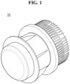
- FIG. 1 is a perspective view of an outer rotor motor according to an embodiment of the present disclosure.
- FIG. 2 is a cross-sectional view of an outer rotor motor according to an embodiment of the present disclosure.
- FIG. 3 is a perspective view of a cover of an outer rotor motor according to an embodiment of the present disclosure.
- FIGS. 4 to 7 are modified examples of a cover of an outer rotor motor according to an embodiment of the present disclosure.
- FIG. 8 is a cross-sectional view of a partial area of a cover of an outer rotor motor according to FIG. 7 .
- an outer rotor motor 10 may include a frame 100, a stator 200, a coil 300, a cover 400, a magnet 500, and a rotating shaft 600, and a controller 700, but may be implemented except for some of the configurations, and does not exclude additional configurations.
- the left side refers to a front in an axial direction and the right side refers to a rear in the axial direction with reference to FIG. 2
- the axial direction may be understood to mean a left-right direction in which the rotating shaft 600 extends with reference to FIG. 2 .
- the frame 100 may be disposed at the rear of the cover 400.
- the stator 200, the coil 300, the magnet 500, and the rotating shaft 600 may be disposed between the frame 100 and the cover 400.
- the controller 700 may be coupled to the rear surface of the frame 100.
- the frame 100 includes a coupling portion 110.
- the coupling portion 110 extends in the axial direction.
- the coupling portion 110 may include a long hole formed in the central region and extending in the axial direction.
- the rotating shaft 600 may be disposed in the long hole of the coupling portion 110.
- the rotating shaft 600 is rotatably coupled to the coupling portion 110.
- the rotating shaft 600 is bearing-coupled to the coupling portion 110.
- the frame 100 may include a flange portion 120.
- the flange portion 120 may extend in a radial direction from the rear of the coupling portion 110.
- the controller 700 may be coupled to the rear surface of the flange portion 120.
- the cover 400 may be disposed in front of the flange portion 120.
- the flange portion 120 may include a groove 122 in which a rear end of the cover 400 is disposed. Through this, it is possible to prevent the cover 400 from being separated to the outside by rotation.
- the stator 200 may be disposed on the frame 100.
- the stator 200 may be disposed on the coupling portion 110 of the frame 100.
- the stator 200 may be disposed on an outer circumferential surface of the coupling portion 110 of the frame 100.
- the stator 200 may be formed in a cylindrical shape.
- the stator 200 may be formed of a plurality of stator units spaced apart in a circumferential direction.
- the stator 200 may face the magnet 500.
- the stator 200 may be disposed inside the magnet 500.
- the stator 200 may be spaced apart from the magnet 500 by a predetermined distance.
- the stator 200 may be fixed to the coupling portion 110 of the frame 100.
- the coil 300 may be disposed on the stator 200.
- the coil 300 may be wound around the stator 200.
- the coil 300 may be electrically connected to the controller 700.
- the cover 400 may be formed in a shape in which the rear surface is opened.
- the cover 400 is coupled to the rotating shaft 600.
- the central region of the front surface of the cover 400 may be penetrated by the rotating shaft 600.
- the rotating shaft 600 may be coupled to the central region of the front surface of the cover 400.
- the cover 400 may surround the stator 200 and the coil 300.
- the side surface of the cover 400 may surround the stator 200 and the coil 300.
- the magnet 500 is disposed on the cover 400.
- the magnet 500 may be coupled to the inside of the side surface of the cover 400.
- the rear end of the cover 400 may be disposed in the groove 122 of the flange portion 120 of the frame 100.
- the rear end of the side surface of the cover 400 may be disposed in the groove 122 of the flange portion 120 of the frame 100.
- the cover 400 may include a fan bracket 410.
- the fan bracket 410 may extend in the radial direction from an outer circumferential surface of the cover 400.
- the fan bracket 410 may extend in the radial direction from the outside of the side surface of the cover 400.
- the fan bracket 410 is described as an example formed integrally with the cover 400, it may be made of a separate member and coupled to the cover 400.
- the fan bracket 410 may be coupled to a fan 20 disposed in front of the outer rotor motor 10.
- the fan bracket 410 may be disposed axially forward than an axially central region of the rotating shaft 600.
- the fan bracket 410 may be disposed axially forward than an axially central region of the stator 200.
- the cover 400 may include a plurality of blades 420.
- the plurality of blades 420 may be formed on the outer circumferential surface of the cover 400.
- the plurality of blades 420 may be formed on an outer surface of the side surface of the cover 400.
- the plurality of blades 420 may extend in the radial direction from the outer circumferential surface of the cover 400.
- the plurality of blades 420 may extend in the radial direction from the outer surface of the side surface of the cover 400.
- the plurality of blades 420 may extend in the axial direction.
- the plurality of blades 420 may extend in the axial direction from the outer circumferential surface of the cover 400.
- the plurality of blades 420 may extend in the axial direction from the outer surface of the side surface of the cover 400.
- the plurality of blades 420 may be spaced apart from each other in the circumferential direction.
- the plurality of blades 420 may be disposed between the fan bracket 410 and the flange portion 120 of the frame 100. Front regions of the plurality of blades 420 may be disposed on the rear surface of the fan bracket 410. The plurality of blades 420 may extend rearward from the rear surface of the fan bracket 410. At least a portion of the plurality of blades 420 may be disposed inside in the radial direction than the radially outer surface of the fan bracket 410. The plurality of blades 420 may be axially spaced apart from the flange portion 120 of the frame 100. The plurality of blades 420 may extend to a region adjacent to the rear end of the cover 400.
- the plurality of blades 420 when the cover 400 rotates in the circumferential direction, the plurality of blades 420 generates a flow of fluid between the fan bracket 410 and the flange portion 120 of the frame 100. That is, it is possible to improve the heat dissipation performance of the cover 400 and inner parts of the cover 400 by convection.
- a radial height of the plurality of blades 420 decreases as the plurality of blades move away from the fan bracket 410.
- the radial height of the plurality of blades 420 decreases as the plurality of blades are adjacent to the flange portion 120 of the frame 100.
- the radially outer surface of the plurality of blades 420 may be formed to be convex outwardly.
- the heat dissipation performance may be improved by increasing the flow of fluid between the fan bracket 410 and the flange portion 120 by forming the radially outer surfaces of the plurality of blades 420 to be formed to be convex toward the outer surface compared to the radially outer surface of the plurality of blades 420 formed in a straight shape.
- the magnet 500 is disposed on the cover 400.
- the magnet 500 is disposed on the inner surface of the cover 400.
- the magnet 500 faces the stator 200.
- the magnet 500 may be disposed to surround the stator 200.
- the magnet 500 may rotate the cover 400, the rotating shaft 600, and the fan 20 in the circumferential direction through electromagnetic interaction with an electric field generated in the stator 200 due to the coil 300.
- the rotating shaft 600 may be rotatably coupled to the frame 100.
- the rotating shaft may be rotatably coupled to a radially central region of the frame 100.
- the rotating shaft 600 is rotatably coupled to the coupling part 110 of the frame 100.
- the rotating shaft 600 is bearing-coupled to the coupling portion 110 of the frame 100.
- the rotating shaft 600 may be coupled to the fan 20.
- the front region of the rotating shaft 600 may be coupled to the fan 200.
- the rotating shaft 600 may pass through the cover 400.
- the rotating shaft 600 may pass through the central region of the front surface of the cover 400.
- the rotating shaft 600 may be coupled to the front surface of the cover 400. Through this, the rotating shaft 600 may rotate integrally with the cover 400.
- the controller 700 may be coupled to the frame 100.
- the controller 700 may be electrically connected to the coil 300.
- the controller 700 may be coupled to the rear surface of the flange portion 120 of the frame 100.
- the controller 700 may include a coupling member 710 coupled to the rear surface of the flange portion 120 of the frame 100 and a substrate 720 disposed on the coupling member 710 and electrically connected to the coil 300.
- the substrate 720 may be a printed circuit board (PCB).
- a heat sink capable of dissipating heat generated by the controller 700 may be installed on the rear surface of the controller 700.
- the plurality of blades 420 may be formed between the rear surface of the fan bracket 410 and the radially outer surface or the outer circumferential surface of the cover 400. Specifically, the plurality of blades 420 may be in contact with the rear surface of the fan bracket 410 and may be in contact with the radially outer surface or the outer circumferential surface of the cover 400.
- the cross-sections of the plurality of blades 420 may have a partial shape of a circle or an ellipse.
- the cross-section of the plurality of blades 420 may have an arc shape.
- the plurality of blades 420 may be spaced apart from each other in the circumferential direction.
- the radial height of the plurality of blades decreases as the plurality of blades move away from the rear surface of the fan bracket. At least a portion of the plurality of blades 420 may be disposed inside in the radial direction than the radially outer surface of the fan bracket 410. The radially outer surface of the plurality of blades may be formed to be convex outwardly.
- the plurality of blades 420 according to FIG. 4 may be formed to have a shorter axial length than the plurality of blades 420 according to FIG. 3 .
- the heat dissipation performance is somewhat lower than that of the plurality of blades 420 according to FIG. 3 , it is possible to reduce the decrease in output of the outer rotor motor 10 while improving manufacturing easiness.
- the flow resistance of the fluid around the cover 400 is reduced compared to the plurality of blades 420 according to FIG. 3 , so there is an advantage in that the output loss of the outer rotor motor 10 is reduced.
- the radially outer surfaces of the plurality of blades 420 may be formed to be concave inwardly. That is, it can be understood that the radially outer surfaces of the plurality of blades 420 according to FIG. 5 are formed to be concave inwardly in the radial direction compared to the plurality of blades 420 according to FIG. 3 .
- the heat dissipation performance is somewhat lower than that of the plurality of blades 420 according to FIG. 3 , but there is an advantage of reducing the decrease in the output of the outer rotor motor 10.
- the flow resistance of the fluid around the cover 400 is reduced compared to the plurality of blades 420 according to FIG. 3 , so there is an advantage in that the output loss of the outer rotor motor 10 is reduced.
- the radially outer surfaces of the plurality of blades 420 may be formed to be concave inwardly. That is, it can be understood that the radially outer surfaces of the plurality of blades 420 according to FIG. 6 are formed to be concave inwardly in the radial direction compared to the plurality of blades 420 according to FIG. 4 .
- the heat dissipation performance is somewhat lower than that of the plurality of blades 420 according to FIG. 4 , but there is an advantage of reducing the decrease in the output of the outer rotor motor 10.
- the flow resistance of the fluid around the cover 400 is reduced compared to the plurality of blades 420 according to FIG. 4 , so there is an advantage in that the output loss of the outer rotor motor 10 is reduced.
- the cover 400 may include a plurality of protrusions 430 extending in the axial direction from the radially outer surface or the outer circumferential surface of the cover 400.
- the plurality of protrusions 430 may be in contact with adjacent protrusions each other.
- the plurality of protrusions 430 may extend from the rear surface of the fan bracket 410 to a region adjacent to the flange portion 120 of the frame 100.
- a cross-sectional area of the plurality of protrusions 430 may decrease as at least some of the plurality of protrusions 430 go outward in the radial direction.
- the cross-sectional area of the plurality of protrusions 430 may decrease as the plurality of protrusions 430 go outward in the radial direction from a region in contact with the adjacent protrusions.
- the plurality of protrusions 430 has the advantage of reducing loss resistance because the flow resistance of the surrounding fluid is reduced due to the shape of the plurality of protrusions 430 compared to the plurality of blades 420.
- a length L in the circumferential direction of the plurality of projections 430 may be twice a height H of a region in which the cross-sectional area of the plurality of projections 430 decreases toward the outside in the radial direction. In this case, compared to the plurality of protrusions 430 having the same cooling performance, it is possible to reduce the output loss of the outer rotor motor 10 by about 1/3.
- the plurality of protrusions 430 have been described as being in contact with each other, but otherwise, the plurality of protrusions 430 may be spaced apart from each other in the circumferential direction. In this case, the adjacent protrusions may be disposed adjacent to each other in the circumferential direction. In this case, the heat dissipation performance can be further improved.
- FIG. 9 is a diagram illustrating a fluid flow of an outer rotor motor according to the prior art.
- FIGS. 10 and 11 are diagrams illustrating a fluid flow of an outer rotor motor according to an embodiment of the present disclosure.
- the outer rotor motor 10 may improve the heat dissipation performance of the cover 400 and the inner parts of the cover 400 by convection.
- the outer rotor motor 10 can increase the heat dissipation effect without a separate configuration such as a cooling wheel, a cooling fan and a flow guide, it is possible to reduce the number of parts of the outer rotor motor 10. In addition, it is possible to reduce the size of the outer rotor motor 10 by simplifying the fastening structure of the parts.
Landscapes
- Engineering & Computer Science (AREA)
- Power Engineering (AREA)
- Mechanical Engineering (AREA)
- General Engineering & Computer Science (AREA)
- Chemical & Material Sciences (AREA)
- Combustion & Propulsion (AREA)
- Physics & Mathematics (AREA)
- Thermal Sciences (AREA)
- Motor Or Generator Cooling System (AREA)
- Connection Of Motors, Electrical Generators, Mechanical Devices, And The Like (AREA)
Claims (9)
- Außenläufermotor, der aufweist:einen Rahmen (100), der einen Kopplungsabschnitt (110), der sich in einer axialen Richtung erstreckt, und einen Flanschabschnitt (120) aufweist, der sich in einer radialen Richtung in einem hinteren Bereich des Kopplungsabschnitts (110) erstreckt;einen Stator (200), der auf einer radial äußeren Oberfläche des Kopplungsabschnitts (110) angeordnet ist;eine Spule (300), die auf dem Stator (200) angeordnet ist;eine Drehwelle (600), die drehbar mit einem radial mittigen Bereich des Kopplungsabschnitts (110) lagergekoppelt ist;eine zylindrische Abdeckung (400), die mit der Drehwelle (600) in einem vorderen Bereich des Kopplungsabschnitts (110) gekoppelt ist und den Stator (200) umgibt; undeinen Magneten (500), der auf der Abdeckung (400) angeordnet ist, mit der Innenseite einer Seitenfläche der Abdeckung (400) gekoppelt ist und dem Stator (200) zugewandt ist,wobei die Abdeckung (400) eine Lüfterhalterung (410) und mehrere Flügel (420) umfasst, wobei sowohl die Lüfterhalterung (410) als auch die mehreren Flügel (420) in einer radialen Richtung von einer radial äußeren Oberfläche der Abdeckung (400) vorstehen und sich die mehreren Flügel (420) in axialer Richtung zwischen der Lüfterhalterung (410) und dem Flanschabschnitt (120) erstrecken, um einen Fluidstrom zwischen der Lüfterhalterung (410) und dem Flanschabschnitt (120) zu erzeugen, um die Wärmeableitungsleistung der Abdeckung (400) und der inneren Teile der Abdeckung (400) zu verbessern.
- Außenläufermotor nach Anspruch 1, wobei eine radiale Höhe der mehreren Flügel (420) abnimmt, je benachbarter die mehreren Flügel zum Flanschabschnitt (120) sind.
- Außenläufermotor nach Anspruch 1 oder 2, wobei sich die mehreren Flügel (420) von einer axialen hinteren Fläche der Lüfterhalterung (410) nach hinten erstrecken.
- Außenläufermotor nach Anspruch 3, wobei sich die mehreren Flügel (420) bis zu einem Bereich erstrecken, der zu einem hinteren Ende der Abdeckung (400) benachbart ist.
- Außenläufermotor nach einem der Ansprüche 1 bis 4, wobei sich die mehreren Flügel (420) nicht weiter in radialer Richtung erstrecken als die radial äußere Oberfläche der Lüfterhalterung (410).
- Außenläufermotor nach einem der Ansprüche 1 bis 5, wobei die radial äußere Oberfläche der mehreren Flügel (420) so geformt ist, dass sie nach außen konvex ist.
- Außenläufermotor nach einem der Ansprüche 1 bis 5, wobei die radial äußere Oberfläche der mehreren Flügel (420) so geformt ist, dass sie nach innen konkav ist.
- Außenläufermotor nach einem der Ansprüche 1 bis 7, wobei die Drehwelle (600) drehbar mit einem radial mittigen Bereich des Rahmens (100) lagergekoppelt ist.
- Außenläufermotor nach einem der Ansprüche 1 bis 7, wobei die Lüfterhalterung (410) axial weiter vorne angeordnet ist als ein axial mittiger Bereich der Drehwelle (600).
Applications Claiming Priority (1)
| Application Number | Priority Date | Filing Date | Title |
|---|---|---|---|
| KR1020210128676A KR20230045863A (ko) | 2021-09-29 | 2021-09-29 | 외전형 모터 |
Publications (2)
| Publication Number | Publication Date |
|---|---|
| EP4160883A1 EP4160883A1 (de) | 2023-04-05 |
| EP4160883B1 true EP4160883B1 (de) | 2025-01-01 |
Family
ID=82899096
Family Applications (1)
| Application Number | Title | Priority Date | Filing Date |
|---|---|---|---|
| EP22190135.8A Active EP4160883B1 (de) | 2021-09-29 | 2022-08-12 | Aussenläufermotor mit integriertem kühlgebläse |
Country Status (3)
| Country | Link |
|---|---|
| US (1) | US20230100753A1 (de) |
| EP (1) | EP4160883B1 (de) |
| KR (1) | KR20230045863A (de) |
Families Citing this family (1)
| Publication number | Priority date | Publication date | Assignee | Title |
|---|---|---|---|---|
| KR102654663B1 (ko) * | 2021-09-29 | 2024-04-05 | 엘지전자 주식회사 | 외전형 모터 |
Citations (22)
| Publication number | Priority date | Publication date | Assignee | Title |
|---|---|---|---|---|
| EP1419568B1 (de) | 2002-08-01 | 2005-05-04 | ebm-papst Mulfingen GmbH & Co.KG | Elektromotor mit hoher ip-schutzart |
| DE102012107109A1 (de) | 2012-08-02 | 2014-02-06 | Ebm-Papst Mulfingen Gmbh & Co. Kg | "Aktive Kühlung eines Motors mit integriertem Kühlkanal" |
| DE102012023477A1 (de) | 2012-11-28 | 2014-05-28 | Ziehl-Abegg Se | Schaltelement für einen Elektromotor, Stator mit einem solchen Schaltelement und Elektromotor |
| US8810086B2 (en) | 2010-09-09 | 2014-08-19 | Ebm-Papst Mulfingen Gmbh & Co. Kg | Rotor for an electric external rotor motor and external rotor motor |
| DE102013003052A1 (de) | 2013-02-20 | 2014-09-04 | Ziehl-Abegg Se | Einrichtung mit einem eine Wicklung aufweisenden Lamellenpaket und Stator für einen Elektromotor mit einer solchen Einrichtung |
| CN204669160U (zh) | 2015-04-02 | 2015-09-23 | 依必安派特穆尔芬根有限两合公司 | 电机 |
| DE102014009146A1 (de) | 2014-06-20 | 2015-12-24 | Ziehl-Abegg Se | Elektromotor mit einem Rotor, einem Stator und einem Elektronikgehäuse sowie Lüfterrad für einen Elektromotor |
| DE102014012946A1 (de) | 2014-08-29 | 2016-03-17 | Ziehl-Abegg Se | Elektronikgehäuse eines Elektromotors sowie Elektromotor mit einem solchen Eletronikgehäuse |
| CN205565971U (zh) | 2015-11-02 | 2016-09-07 | 依必安派特穆尔芬根有限两合公司 | 电机 |
| DE10313273B9 (de) | 2003-03-24 | 2016-10-20 | Ebm-Papst Mulfingen Gmbh & Co. Kg | Elektromotor mit hoher IP-Schutzart |
| US9667105B2 (en) | 2014-05-22 | 2017-05-30 | Delta Electronics, Inc. | Motor rotor and positioning ring thereof |
| EP3327902A1 (de) | 2016-11-23 | 2018-05-30 | Nicotra Gebhardt S.P.A. | Aussenläufer-elektromotor |
| DE102016015535A1 (de) | 2016-12-19 | 2018-06-21 | Ziehl-Abegg Se | Kühlvorrichtung eines Elektromotors sowie Elektromotor mit Kühlvorrichtung |
| DE102017003992A1 (de) | 2017-04-19 | 2018-10-25 | Ziehl-Abegg Se | Magnetgestützter EC-Motor, insbesondere Synchron-EC-Motor, und Verfahren zur Drehfelderzeugung bei einem magnetgestützten EC-Motor |
| CN209233661U (zh) | 2018-12-17 | 2019-08-09 | 中山大洋电机股份有限公司 | 一种外转子电机 |
| DE102018005365A1 (de) | 2018-07-03 | 2020-01-09 | Ziehl-Abegg Se | Elektromotor, insbesondere EC-Motor, und Kühlkörper für einen Elektromotor |
| DE102018005364A1 (de) | 2018-07-03 | 2020-01-09 | Ziehl-Abegg Se | Elektromotor, insbesondere EC-Motor |
| US20200403472A1 (en) | 2019-06-19 | 2020-12-24 | Delta Electronics, Inc. | Motor |
| CN213402646U (zh) | 2020-10-27 | 2021-06-08 | 湖北惠洋电器制造有限公司 | 一种外转子电机系统 |
| WO2021196516A1 (zh) | 2020-03-28 | 2021-10-07 | 中山大洋电机股份有限公司 | 一种外转子电机 |
| EP3965268A1 (de) | 2020-09-07 | 2022-03-09 | HIDRIA d.o.o. | Elektromotor mit belüftetem elektronikgehäuse |
| CN216774407U (zh) | 2021-11-17 | 2022-06-17 | 中山大洋电机股份有限公司 | 一种带新型散热结构的外转子电机 |
Family Cites Families (6)
| Publication number | Priority date | Publication date | Assignee | Title |
|---|---|---|---|---|
| JP3809438B2 (ja) * | 2003-11-28 | 2006-08-16 | 日本サーボ株式会社 | 遠心ブロワ |
| JP4992287B2 (ja) * | 2006-04-28 | 2012-08-08 | 日本電産株式会社 | モータ |
| JP4731639B1 (ja) * | 2010-10-06 | 2011-07-27 | 三菱電機株式会社 | 回転電機、軸受着脱用治具、および軸受交換方法 |
| CN102817858B (zh) * | 2011-06-08 | 2017-04-19 | 富准精密工业(深圳)有限公司 | 定子及具有该定子的散热风扇 |
| KR20200068887A (ko) | 2018-12-06 | 2020-06-16 | 엘지전자 주식회사 | 터보팬 및 이를 포함하는 공기조화기 |
| JPWO2020202390A1 (de) * | 2019-03-29 | 2020-10-08 |
-
2021
- 2021-09-29 KR KR1020210128676A patent/KR20230045863A/ko not_active Ceased
-
2022
- 2022-08-12 EP EP22190135.8A patent/EP4160883B1/de active Active
- 2022-08-25 US US17/895,434 patent/US20230100753A1/en active Pending
Patent Citations (22)
| Publication number | Priority date | Publication date | Assignee | Title |
|---|---|---|---|---|
| EP1419568B1 (de) | 2002-08-01 | 2005-05-04 | ebm-papst Mulfingen GmbH & Co.KG | Elektromotor mit hoher ip-schutzart |
| DE10313273B9 (de) | 2003-03-24 | 2016-10-20 | Ebm-Papst Mulfingen Gmbh & Co. Kg | Elektromotor mit hoher IP-Schutzart |
| US8810086B2 (en) | 2010-09-09 | 2014-08-19 | Ebm-Papst Mulfingen Gmbh & Co. Kg | Rotor for an electric external rotor motor and external rotor motor |
| DE102012107109A1 (de) | 2012-08-02 | 2014-02-06 | Ebm-Papst Mulfingen Gmbh & Co. Kg | "Aktive Kühlung eines Motors mit integriertem Kühlkanal" |
| DE102012023477A1 (de) | 2012-11-28 | 2014-05-28 | Ziehl-Abegg Se | Schaltelement für einen Elektromotor, Stator mit einem solchen Schaltelement und Elektromotor |
| DE102013003052A1 (de) | 2013-02-20 | 2014-09-04 | Ziehl-Abegg Se | Einrichtung mit einem eine Wicklung aufweisenden Lamellenpaket und Stator für einen Elektromotor mit einer solchen Einrichtung |
| US9667105B2 (en) | 2014-05-22 | 2017-05-30 | Delta Electronics, Inc. | Motor rotor and positioning ring thereof |
| DE102014009146A1 (de) | 2014-06-20 | 2015-12-24 | Ziehl-Abegg Se | Elektromotor mit einem Rotor, einem Stator und einem Elektronikgehäuse sowie Lüfterrad für einen Elektromotor |
| DE102014012946A1 (de) | 2014-08-29 | 2016-03-17 | Ziehl-Abegg Se | Elektronikgehäuse eines Elektromotors sowie Elektromotor mit einem solchen Eletronikgehäuse |
| CN204669160U (zh) | 2015-04-02 | 2015-09-23 | 依必安派特穆尔芬根有限两合公司 | 电机 |
| CN205565971U (zh) | 2015-11-02 | 2016-09-07 | 依必安派特穆尔芬根有限两合公司 | 电机 |
| EP3327902A1 (de) | 2016-11-23 | 2018-05-30 | Nicotra Gebhardt S.P.A. | Aussenläufer-elektromotor |
| DE102016015535A1 (de) | 2016-12-19 | 2018-06-21 | Ziehl-Abegg Se | Kühlvorrichtung eines Elektromotors sowie Elektromotor mit Kühlvorrichtung |
| DE102017003992A1 (de) | 2017-04-19 | 2018-10-25 | Ziehl-Abegg Se | Magnetgestützter EC-Motor, insbesondere Synchron-EC-Motor, und Verfahren zur Drehfelderzeugung bei einem magnetgestützten EC-Motor |
| DE102018005365A1 (de) | 2018-07-03 | 2020-01-09 | Ziehl-Abegg Se | Elektromotor, insbesondere EC-Motor, und Kühlkörper für einen Elektromotor |
| DE102018005364A1 (de) | 2018-07-03 | 2020-01-09 | Ziehl-Abegg Se | Elektromotor, insbesondere EC-Motor |
| CN209233661U (zh) | 2018-12-17 | 2019-08-09 | 中山大洋电机股份有限公司 | 一种外转子电机 |
| US20200403472A1 (en) | 2019-06-19 | 2020-12-24 | Delta Electronics, Inc. | Motor |
| WO2021196516A1 (zh) | 2020-03-28 | 2021-10-07 | 中山大洋电机股份有限公司 | 一种外转子电机 |
| EP3965268A1 (de) | 2020-09-07 | 2022-03-09 | HIDRIA d.o.o. | Elektromotor mit belüftetem elektronikgehäuse |
| CN213402646U (zh) | 2020-10-27 | 2021-06-08 | 湖北惠洋电器制造有限公司 | 一种外转子电机系统 |
| CN216774407U (zh) | 2021-11-17 | 2022-06-17 | 中山大洋电机股份有限公司 | 一种带新型散热结构的外转子电机 |
Also Published As
| Publication number | Publication date |
|---|---|
| US20230100753A1 (en) | 2023-03-30 |
| EP4160883A1 (de) | 2023-04-05 |
| KR20230045863A (ko) | 2023-04-05 |
Similar Documents
| Publication | Publication Date | Title |
|---|---|---|
| JP4015016B2 (ja) | ターボファン及びこれを用いた空気調和機 | |
| KR100574860B1 (ko) | 에어컨 실내기의 송풍팬 구조 | |
| EP4160873A1 (de) | Aussenläufermotor | |
| EP1050720B1 (de) | Klimaanlage | |
| US12410939B2 (en) | Air conditioner | |
| KR100981859B1 (ko) | 분리형 공기조화기용 실외기 | |
| EP4160883B1 (de) | Aussenläufermotor mit integriertem kühlgebläse | |
| CN106871266B (zh) | 空气调节器 | |
| JP4403823B2 (ja) | 冷却装置 | |
| KR20060027916A (ko) | 시로코팬 및 이를 구비한 공기조화기 | |
| JP6974760B2 (ja) | モータ組立体、及び、空気調和装置 | |
| KR100332774B1 (ko) | 에어컨 실외기 | |
| CN109654606B (zh) | 窗式空调器 | |
| EP1245908A2 (de) | Klimaanlage und Innenraumeinheit dafür | |
| WO2010058666A1 (ja) | 空気調和機 | |
| KR100335082B1 (ko) | 창문형 에어컨의 실외기 | |
| CN222417727U (zh) | 挂式空调 | |
| CN224188683U (zh) | 侧出风窗式空调器 | |
| JP7658646B1 (ja) | ファン及び空気調和装置 | |
| CN224033915U (zh) | 空调 | |
| CN222668474U (zh) | 一种风机系统及应用有该风机系统的吸油烟机 | |
| CN217004681U (zh) | 离心风扇和具有其的空调器 | |
| JP4045247B2 (ja) | 一体型空気調和機 | |
| KR200184572Y1 (ko) | 공기조화기용 실내기의 송풍기 장착구조 | |
| JPH07336930A (ja) | ファンモータ |
Legal Events
| Date | Code | Title | Description |
|---|---|---|---|
| PUAI | Public reference made under article 153(3) epc to a published international application that has entered the european phase |
Free format text: ORIGINAL CODE: 0009012 |
|
| STAA | Information on the status of an ep patent application or granted ep patent |
Free format text: STATUS: REQUEST FOR EXAMINATION WAS MADE |
|
| 17P | Request for examination filed |
Effective date: 20220912 |
|
| AK | Designated contracting states |
Kind code of ref document: A1 Designated state(s): AL AT BE BG CH CY CZ DE DK EE ES FI FR GB GR HR HU IE IS IT LI LT LU LV MC MK MT NL NO PL PT RO RS SE SI SK SM TR |
|
| RBV | Designated contracting states (corrected) |
Designated state(s): AL AT BE BG CH CY CZ DE DK EE ES FI FR GB GR HR HU IE IS IT LI LT LU LV MC MK MT NL NO PL PT RO RS SE SI SK SM TR |
|
| GRAP | Despatch of communication of intention to grant a patent |
Free format text: ORIGINAL CODE: EPIDOSNIGR1 |
|
| STAA | Information on the status of an ep patent application or granted ep patent |
Free format text: STATUS: GRANT OF PATENT IS INTENDED |
|
| INTG | Intention to grant announced |
Effective date: 20241015 |
|
| RIC1 | Information provided on ipc code assigned before grant |
Ipc: H02K 7/14 20060101ALN20241008BHEP Ipc: H02K 21/22 20060101ALN20241008BHEP Ipc: H02K 7/08 20060101ALN20241008BHEP Ipc: F04D 29/58 20060101ALI20241008BHEP Ipc: F04D 25/08 20060101ALI20241008BHEP Ipc: F04D 17/16 20060101ALI20241008BHEP Ipc: F24F 1/00 20190101ALI20241008BHEP Ipc: H02K 9/14 20060101AFI20241008BHEP |
|
| GRAS | Grant fee paid |
Free format text: ORIGINAL CODE: EPIDOSNIGR3 |
|
| GRAA | (expected) grant |
Free format text: ORIGINAL CODE: 0009210 |
|
| STAA | Information on the status of an ep patent application or granted ep patent |
Free format text: STATUS: THE PATENT HAS BEEN GRANTED |
|
| AK | Designated contracting states |
Kind code of ref document: B1 Designated state(s): AL AT BE BG CH CY CZ DE DK EE ES FI FR GB GR HR HU IE IS IT LI LT LU LV MC MK MT NL NO PL PT RO RS SE SI SK SM TR |
|
| REG | Reference to a national code |
Ref country code: GB Ref legal event code: FG4D |
|
| REG | Reference to a national code |
Ref country code: CH Ref legal event code: EP |
|
| REG | Reference to a national code |
Ref country code: DE Ref legal event code: R096 Ref document number: 602022009269 Country of ref document: DE |
|
| REG | Reference to a national code |
Ref country code: IE Ref legal event code: FG4D |
|
| REG | Reference to a national code |
Ref country code: LT Ref legal event code: MG9D |
|
| REG | Reference to a national code |
Ref country code: NL Ref legal event code: MP Effective date: 20250101 |
|
| REG | Reference to a national code |
Ref country code: AT Ref legal event code: MK05 Ref document number: 1757319 Country of ref document: AT Kind code of ref document: T Effective date: 20250101 |
|
| PG25 | Lapsed in a contracting state [announced via postgrant information from national office to epo] |
Ref country code: NL Free format text: LAPSE BECAUSE OF FAILURE TO SUBMIT A TRANSLATION OF THE DESCRIPTION OR TO PAY THE FEE WITHIN THE PRESCRIBED TIME-LIMIT Effective date: 20250101 |
|
| PG25 | Lapsed in a contracting state [announced via postgrant information from national office to epo] |
Ref country code: FI Free format text: LAPSE BECAUSE OF FAILURE TO SUBMIT A TRANSLATION OF THE DESCRIPTION OR TO PAY THE FEE WITHIN THE PRESCRIBED TIME-LIMIT Effective date: 20250101 |
|
| PG25 | Lapsed in a contracting state [announced via postgrant information from national office to epo] |
Ref country code: PL Free format text: LAPSE BECAUSE OF FAILURE TO SUBMIT A TRANSLATION OF THE DESCRIPTION OR TO PAY THE FEE WITHIN THE PRESCRIBED TIME-LIMIT Effective date: 20250101 |
|
| PG25 | Lapsed in a contracting state [announced via postgrant information from national office to epo] |
Ref country code: ES Free format text: LAPSE BECAUSE OF FAILURE TO SUBMIT A TRANSLATION OF THE DESCRIPTION OR TO PAY THE FEE WITHIN THE PRESCRIBED TIME-LIMIT Effective date: 20250101 |
|
| PG25 | Lapsed in a contracting state [announced via postgrant information from national office to epo] |
Ref country code: IS Free format text: LAPSE BECAUSE OF FAILURE TO SUBMIT A TRANSLATION OF THE DESCRIPTION OR TO PAY THE FEE WITHIN THE PRESCRIBED TIME-LIMIT Effective date: 20250501 Ref country code: NO Free format text: LAPSE BECAUSE OF FAILURE TO SUBMIT A TRANSLATION OF THE DESCRIPTION OR TO PAY THE FEE WITHIN THE PRESCRIBED TIME-LIMIT Effective date: 20250401 |
|
| PG25 | Lapsed in a contracting state [announced via postgrant information from national office to epo] |
Ref country code: HR Free format text: LAPSE BECAUSE OF FAILURE TO SUBMIT A TRANSLATION OF THE DESCRIPTION OR TO PAY THE FEE WITHIN THE PRESCRIBED TIME-LIMIT Effective date: 20250101 |
|
| PG25 | Lapsed in a contracting state [announced via postgrant information from national office to epo] |
Ref country code: PT Free format text: LAPSE BECAUSE OF FAILURE TO SUBMIT A TRANSLATION OF THE DESCRIPTION OR TO PAY THE FEE WITHIN THE PRESCRIBED TIME-LIMIT Effective date: 20250502 Ref country code: LV Free format text: LAPSE BECAUSE OF FAILURE TO SUBMIT A TRANSLATION OF THE DESCRIPTION OR TO PAY THE FEE WITHIN THE PRESCRIBED TIME-LIMIT Effective date: 20250101 |
|
| PG25 | Lapsed in a contracting state [announced via postgrant information from national office to epo] |
Ref country code: BG Free format text: LAPSE BECAUSE OF FAILURE TO SUBMIT A TRANSLATION OF THE DESCRIPTION OR TO PAY THE FEE WITHIN THE PRESCRIBED TIME-LIMIT Effective date: 20250101 Ref country code: GR Free format text: LAPSE BECAUSE OF FAILURE TO SUBMIT A TRANSLATION OF THE DESCRIPTION OR TO PAY THE FEE WITHIN THE PRESCRIBED TIME-LIMIT Effective date: 20250402 |
|
| PG25 | Lapsed in a contracting state [announced via postgrant information from national office to epo] |
Ref country code: AT Free format text: LAPSE BECAUSE OF FAILURE TO SUBMIT A TRANSLATION OF THE DESCRIPTION OR TO PAY THE FEE WITHIN THE PRESCRIBED TIME-LIMIT Effective date: 20250101 |
|
| PG25 | Lapsed in a contracting state [announced via postgrant information from national office to epo] |
Ref country code: CZ Free format text: LAPSE BECAUSE OF FAILURE TO SUBMIT A TRANSLATION OF THE DESCRIPTION OR TO PAY THE FEE WITHIN THE PRESCRIBED TIME-LIMIT Effective date: 20250101 |
|
| PG25 | Lapsed in a contracting state [announced via postgrant information from national office to epo] |
Ref country code: SE Free format text: LAPSE BECAUSE OF FAILURE TO SUBMIT A TRANSLATION OF THE DESCRIPTION OR TO PAY THE FEE WITHIN THE PRESCRIBED TIME-LIMIT Effective date: 20250101 |
|
| REG | Reference to a national code |
Ref country code: DE Ref legal event code: R026 Ref document number: 602022009269 Country of ref document: DE |
|
| PLBI | Opposition filed |
Free format text: ORIGINAL CODE: 0009260 |
|
| PG25 | Lapsed in a contracting state [announced via postgrant information from national office to epo] |
Ref country code: SM Free format text: LAPSE BECAUSE OF FAILURE TO SUBMIT A TRANSLATION OF THE DESCRIPTION OR TO PAY THE FEE WITHIN THE PRESCRIBED TIME-LIMIT Effective date: 20250101 |
|
| REG | Reference to a national code |
Ref country code: CH Ref legal event code: L10 Free format text: ST27 STATUS EVENT CODE: U-0-0-L10-L00 (AS PROVIDED BY THE NATIONAL OFFICE) Effective date: 20251008 |
|
| PG25 | Lapsed in a contracting state [announced via postgrant information from national office to epo] |
Ref country code: DK Free format text: LAPSE BECAUSE OF FAILURE TO SUBMIT A TRANSLATION OF THE DESCRIPTION OR TO PAY THE FEE WITHIN THE PRESCRIBED TIME-LIMIT Effective date: 20250101 |
|
| PGFP | Annual fee paid to national office [announced via postgrant information from national office to epo] |
Ref country code: DE Payment date: 20250707 Year of fee payment: 4 |
|
| PGFP | Annual fee paid to national office [announced via postgrant information from national office to epo] |
Ref country code: IT Payment date: 20250901 Year of fee payment: 4 |
|
| PLAX | Notice of opposition and request to file observation + time limit sent |
Free format text: ORIGINAL CODE: EPIDOSNOBS2 |
|
| PG25 | Lapsed in a contracting state [announced via postgrant information from national office to epo] |
Ref country code: EE Free format text: LAPSE BECAUSE OF FAILURE TO SUBMIT A TRANSLATION OF THE DESCRIPTION OR TO PAY THE FEE WITHIN THE PRESCRIBED TIME-LIMIT Effective date: 20250101 |
|
| PG25 | Lapsed in a contracting state [announced via postgrant information from national office to epo] |
Ref country code: RO Free format text: LAPSE BECAUSE OF FAILURE TO SUBMIT A TRANSLATION OF THE DESCRIPTION OR TO PAY THE FEE WITHIN THE PRESCRIBED TIME-LIMIT Effective date: 20250101 |
|
| PG25 | Lapsed in a contracting state [announced via postgrant information from national office to epo] |
Ref country code: SK Free format text: LAPSE BECAUSE OF FAILURE TO SUBMIT A TRANSLATION OF THE DESCRIPTION OR TO PAY THE FEE WITHIN THE PRESCRIBED TIME-LIMIT Effective date: 20250101 |
|
| 26 | Opposition filed |
Opponent name: ZIEHL-ABEGG SE Effective date: 20250930 |
|
| PLBB | Reply of patent proprietor to notice(s) of opposition received |
Free format text: ORIGINAL CODE: EPIDOSNOBS3 |
|
| REG | Reference to a national code |
Ref country code: CH Ref legal event code: H13 Free format text: ST27 STATUS EVENT CODE: U-0-0-H10-H13 (AS PROVIDED BY THE NATIONAL OFFICE) Effective date: 20260324 |
|
| PG25 | Lapsed in a contracting state [announced via postgrant information from national office to epo] |
Ref country code: MC Free format text: LAPSE BECAUSE OF FAILURE TO SUBMIT A TRANSLATION OF THE DESCRIPTION OR TO PAY THE FEE WITHIN THE PRESCRIBED TIME-LIMIT Effective date: 20250101 |
|
| PG25 | Lapsed in a contracting state [announced via postgrant information from national office to epo] |
Ref country code: LU Free format text: LAPSE BECAUSE OF NON-PAYMENT OF DUE FEES Effective date: 20250812 |
|
| PG25 | Lapsed in a contracting state [announced via postgrant information from national office to epo] |
Ref country code: CH Free format text: LAPSE BECAUSE OF NON-PAYMENT OF DUE FEES Effective date: 20250831 |