EP4160628B1 - Verfahren zum recycling von mindestens einem magneten und anlage zur durchführung eines solchen verfahrens - Google Patents
Verfahren zum recycling von mindestens einem magneten und anlage zur durchführung eines solchen verfahrens Download PDFInfo
- Publication number
- EP4160628B1 EP4160628B1 EP22198180.6A EP22198180A EP4160628B1 EP 4160628 B1 EP4160628 B1 EP 4160628B1 EP 22198180 A EP22198180 A EP 22198180A EP 4160628 B1 EP4160628 B1 EP 4160628B1
- Authority
- EP
- European Patent Office
- Prior art keywords
- magnet
- magnets
- neutralization container
- demagnetization
- container
- Prior art date
- Legal status (The legal status is an assumption and is not a legal conclusion. Google has not performed a legal analysis and makes no representation as to the accuracy of the status listed.)
- Active
Links
Images


Classifications
-
- H—ELECTRICITY
- H01—ELECTRIC ELEMENTS
- H01F—MAGNETS; INDUCTANCES; TRANSFORMERS; SELECTION OF MATERIALS FOR THEIR MAGNETIC PROPERTIES
- H01F13/00—Apparatus or processes for magnetising or demagnetising
- H01F13/006—Methods and devices for demagnetising of magnetic bodies, e.g. workpieces, sheet material
Definitions
- the present invention relates to the field of magnet recycling. More precisely, the invention relates to the recycling of so-called high-power permanent magnets, such as those found in industrial machines.
- a "high power magnet” a permanent magnet, based on rare earths, whose remanent magnetic field, that is to say in the absence of any magnetic excitation, is of the order of less than 1 T (Tesla).
- This type of magnet is found in particular in rotating electrical machines, such as wind turbine motors or generators, in measuring devices and instruments equipped with permanent magnets, for example an MRI machine in the medical field, or more generally in any system and equipment requiring a high-power electromagnetic field.
- the magnetism of permanent magnets can degrade over time, for example under the effect of heat: their intrinsic power is reduced and/or they dislocate and/or they become detached from their support. In order to maintain optimal performance of the electrical machine, it is then necessary to remagnetize the magnets partially or completely, or to replace them. Remagnetization can be carried out inside the machine or outside. For remagnetization outside the machine or to replace the magnets, they must be extracted from the machine, either using tools specific to the machine, or by partially or completely dismantling the machine.
- the magnet extracted from the machine is assembled with a support, or sole, forming a magnetic pole. Other elements can also be assembled to the pole. We then speak of a magnetic block.
- the magnet It is also known to demagnetize a magnet by heating it beyond its so-called Curie temperature.
- the magnet heated above this temperature loses its magnetic properties, and then becomes non-magnetic on a daily scale.
- the magnet is placed in an oven, preferably under a controlled atmosphere.
- a known advantage is that by heating the magnet in this way, it is then separated from the elements which form the magnetic block.
- the magnetic block is generally assembled using glue-type binders or adhesives. When heated, the glue melts and/or evaporates, allowing the magnet to be released.
- the magnet thus demagnetized can then be recycled as needed, for example by recovering the materials constituting it.
- the document JP2012-175826 A , the document US2014/0366687 and the document US2012/0137829 each describe an example of a demagnetization process involving heating the magnet.
- a problem with this type of process is that the stronger the magnet, the greater the risk of interaction with demagnetizing equipment.
- a high-power magnet it can interact with the walls of the oven, by sticking to them, or even with the environment of the oven, the magnet then behaving like a projectile or causing the creation of projectiles. from objects in the oven environment. Operator safety is at stake.
- the magnets especially when they are of high power, are also preferably passed one by one into the oven, carefully, making these processes expensive and difficult to implement in an industrial setting.
- a first object of the invention is to propose a recycling process adapted to high-power magnets, that is to say of the order of 1T and beyond.
- a second object of the invention is to propose a recycling process adapted to the simultaneous treatment of a plurality of magnets.
- a third object of the invention is to propose a recycling process allowing almost total demagnetization of the treated magnets.
- a fourth object of the invention is to propose a recycling process in which the demagnetized magnets obtained are clean.
- a fifth object of the invention is to propose a recycling process limiting the incorporation of impurities into the material of the magnets.
- a sixth object of the invention is to propose a recycling process adapted to industrial requirements, particularly in terms of costs and speed.
- a seventh object of the invention is to propose a recycling process increasing the safety of the people who operate it.
- the invention relates to a process for recycling at least one magnet in a recycling installation.
- the method notably comprises a step of demagnetizing the at least one magnet.
- the method further comprises a step of placing the magnet inside a neutralization container, said neutralization container comprising walls forming a closed receptacle to contain said at least one magnet, the walls being made at least partly of non-magnetic metallic material.
- the magnet is contained in the neutralization container during at least part of the demagnetization step.
- the neutralization container thus makes it possible to contain at least one magnet, or a plurality of magnets, during the demagnetization step with increased safety for the equipment and increased safety for the surrounding personnel, even for high-power magnets. .
- the magnet is, during at least part of the demagnetization step, part of a magnetic block comprising elements assembled at least in part by binder to the magnet.
- the magnetic block may come apart during the demagnetization stage. The process thus makes it possible to avoid having to strictly clean a magnet before the demagnetization step. The process is simplified and costs reduced.
- the demagnetization step comprises at least one heating operation to a maximum temperature greater than or equal to the Curie temperature of the at least one magnet to be demagnetized.
- Demagnetization by heating ensures effective demagnetization in addition to, where applicable, simultaneously allow part of the glues and other binders of the magnetic block to melt, facilitating or even initiating the dislocation of the magnetic block.
- the separation of the magnet from the rest of the elements of the magnetic block and sorting are simplified, and the recovery of the magnet is improved.
- the demagnetization step comprises at least one pulse cycling operation of decreasing electromagnetic fields, in combination or as a variant of demagnetization by heating.
- the magnet, and where appropriate the magnetic block can be reused as such, for example after remagnetization.
- a step of heating the magnet to a temperature lower than the Curie temperature of the magnet making it possible to finalize the dislocation of the magnetic block and/or the cleaning the magnet.
- This heating step is particularly useful when the demagnetization step is carried out solely by the pulse cycling operation of decreasing electromagnetic fields.
- a step of cleaning the magnet which may include a dislocation of the magnet, in order to obtain the magnet physically separated from the other elements of the magnetic block, and clean glue, varnish and other possible binders or coatings.
- the valuation of the magnet is increased.
- the method is particularly suitable for recycling a plurality of magnets placed together in the neutralization container during the demagnetization step.
- the step of placing the plurality of magnets can be carried out by pouring the plurality of magnets loose into the neutralization container. No particular organization of the magnets is to be expected, facilitating loading of the neutralization container, and making it possible to increase recycling rates.
- the method may comprise a preliminary step of collecting at least part of the plurality of magnets in an intermediate collector.
- the step of placing it in the neutralization container may include an operation of pouring the contents of the intermediate collector into the neutralization container.
- a reel can be used at the interface between the intermediate collector and the neutralization container to safely discharge the magnets. Indeed, by pouring several magnets at the same time, especially when they are of high power, the magnets seek to position themselves in relation to each other according to their magnetic field lines, so that they can be ejected in several directions as it passes between the collector and the neutralization container.
- the dispenser allows you to guide the magnets into the receptacle of the neutralization container in complete safety.
- the method may further comprise a preliminary collection step and a transport step of the at least one magnet.
- the collection step comprises for example the extraction of the at least one magnet from a machine on an operating site of the machine
- the transport step comprises for example the transport from the operating site of the machine to the recycling plant.
- the placement step in the neutralization container is then carried out before the transport step, so that the at least one magnet is contained in the neutralization container during the transport step.
- the number of manipulations of the magnet is reduced; the magnet being brought to site already in the neutralization container, ready to undergo the demagnetization step.
- the non-magnetic material is an austenitic stainless steel, easy to find and inexpensive.
- the at least one magnet is a high-power magnet
- the neutralization container neutralizing at least partly its dangerous effects on the equipment and on the operating personnel.
- the invention relates to an installation for recycling at least one magnet for implementing the demagnetization process as presented above, comprising at least one demagnetization station and at least one placement station in a neutralization container.
- Said neutralization container comprises walls forming a closed receptacle for said at least one magnet, the walls being made at least partly of non-magnetic metallic material.
- the invention concerns the recycling of used magnets, from their collection to their revaluation, which includes in particular the demagnetization of used magnets. More specifically, but without this being limiting, the invention will find a particular application for the recycling of high-power magnets, that is to say whose remanent magnetic field, also called remanent magnetic induction, is l order of 1 T or more. Even more particularly, the invention applies to high-power and permanent magnets, and possibly based on rare earths. These magnets are, in a widespread manner, of the ferromagnetic type, but the invention can be applied to other types of magnets, and for example to antiferromagnetic magnets.
- the installation 1 includes a demagnetization station 2, in which one or more magnets D to be recycled are demagnetized.
- demagnetization we define here the action of reducing the remanent magnetic field and/or the coercive magnetic field of a magnet to a value at which it no longer exerts on its environment and the environment no longer exerts no longer any visible and/or measurable effect on normal scales.
- the demagnetized magnet then becomes, for example, paramagnetic.
- magnetic field means the remanent magnetic field, or the coercive magnetic field, or both.
- the demagnetization station 2 comprises for example a demagnetization oven 3, designed to be able to heat at least one magnet to be recycled to a temperature greater than or equal to its demagnetization temperature.
- the demagnetization temperature depends on the nature of the magnet to be demagnetized. In the case of a ferromagnetic magnet, this temperature is known as the Curie temperature. For an antiferromagnet, it is called Néel temperature. In the remainder of the description, we will only speak of Curie temperature, it being understood that the description is immediately adaptable to antiferromagnetic magnets.
- the demagnetization oven 3 is for example a radiant or burner oven.
- the atmosphere in oven 3 is controlled.
- the oven 3 may comprise a closed enclosure 4, and a system for injecting a gas (not shown) into the enclosure 4.
- the oven 3 is also equipped with a system 5 making it possible to adjust and control the temperature, as well as possibly the pressure, in enclosure 4.
- Demagnetization can thus be carried out at low pressure, with injection of an inert gas, for example argon, so as to limit pollution of the magnet during heating particularly by the light elements of air (oxygen, carbon and nitrogen).
- the demagnetization station 2 may include a demagnetizer tunnel 6, generating a maximum magnetic field greater than that of the magnets to be demagnetized. More precisely, it is a demagnetization by cycling by decreasing alternating electromagnetic pulses. Demagnetization according to this technique allows, by avoiding heating the magnet, to preserve its integrity, unlike the passage in the oven 3 which can alter the properties of the materials constituting the magnet and make it unusable as a new magnet. Demagnetization by cycling by alternating electromagnetic pulses is therefore used in particular when the magnet must be reused such as, after remagnetization for example.
- the demagnetization station 2 can include either only the oven 3, or only the tunnel 6, or both. In the latter case, each magnet D to be demagnetized passes successively through one then the other.
- each magnet D to be demagnetized first passes through the tunnel 6 then into the oven 3.
- the demagnetization furnace 3 can include burners, the quantity of combustion gas consumed to demagnetize a magnet can be reduced by a prior passage through the tunnel 3.
- a magnet is generally part of an assembly, forming a magnetic block, within which elements are assembled to the magnet, and which may include binders or adhesives. , such as glue, and/or possibly varnish, resins and silicones, which it is desirable to eliminate for recycling.
- the tunnel 6 is thus preferably followed by at least one oven which is not necessarily the demagnetization oven 3, and which may be an oven which does not reach the Curie temperature of the magnet to be demagnetized. Passing through an oven thus allows at least the softening, even the fusion, or even the calcination of the adhesives and others, so as to allow the decomposition of the magnetic block.
- This decomposition is carried out in the demagnetization oven 3 at the same time as the demagnetization.
- the demagnetization station 2 may include any device making it possible to reduce or cancel the remanent magnetic field of the magnet.
- a high-power magnet interacts strongly with its environment, in a dangerous way.
- it interacts with the equipment of demagnetization station 2.
- a magnet of strong power can move masses of several hundred kilograms (kg), for example up to 5000 kg. It can thus stick to the walls inside the enclosure 4 of the oven 3 or inside the tunnel 6, and cause the movement of heavy objects in the environment of the demagnetization installation. It can also behave like a dangerous projectile for operators who have to handle it.
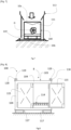
- the demagnetization installation 1 comprises, upstream of the demagnetization station 2, a station 7 for placing the magnet in a neutralization container 8 .
- the neutralization container 8 is sold under the name “Daimag Box”.
- Said neutralization container 8 comprises walls 9, 10a, 10b delimiting an interior space which forms a closed receptacle to contain the magnet to be demagnetized. At least one of these walls 9, 10a, 10b comprises a removable closure system, giving or blocking access to the receptacle inside the neutralization container 8.
- the removable closure system is formed by a so-called upper wall 10a, which is articulated relative to the other walls.
- the neutralization container 8 then comprises a lower wall 10b opposite the upper wall 10a, forming a bottom.
- the other walls 9 are called side walls.
- the neutralization container 8 is intended to rest on the ground, directly or indirectly, by the bottom 10b.
- the walls 9, 10a, 10b of the container 8 are made at least partly, and preferably entirely, of non-magnetic metallic material.
- non-magnetic material we designate here any material which is not affected, on measurable scales, by an external magnetic field, and whose remanent and/or coercive magnetic field does not exert any action on its environment, on normal scales.
- a non-magnetic material can in particular be paramagnetic.
- the walls 9, 10a, 10b of the container 8 are made of austenitic stainless steel. According to one embodiment, it is 304 stainless steel (AISI designation), easily available.
- the walls 9, 10a, 10b of the neutralization container 8 may include holes allowing any fumes produced during passage through an oven of the installation 1 to escape. A rise in pressure inside the neutralization container 8, which could be dangerous, is thus avoided.
- at least one of the side walls 9 can be provided with at least two series of holes, each series being made near the upper wall 10a or the lower wall 10b.
- a magnet is thus placed in the neutralization container 8 before its entry into the station 2 and is contained there during at least part, and preferably during the whole, of its passage in the demagnetization station 2. While being contained in the neutralization container 8, the magnetic field of the magnet to be demagnetized remains contained in the neutralization container 8 and does not affect the demagnetizing oven 3 and/or the tunnel 6 and/or any equipment in the environment of recycling installation 1.
- the dimensions of the neutralization container 8 can be determined as a function of the magnet(s) which are intended to be placed in the receptacle. Indeed, the larger the container 8, the greater the attenuation effect of the electromagnetic field of the magnet(s). It is therefore a question of finding a compromise between the attenuation of the electromagnetic field and the size of the neutralization container 8.
- installation 1 can be provided to recycle several magnets.
- the neutralization container 8 can contain several magnets simultaneously.
- the demagnetization station 2 is set to the strictest condition, so as to allow the demagnetization of all the magnets in the container 8.
- the Magnetic blocks can be prepared, weighed, characterized and sorted, manually or otherwise, into different categories. They can also be partially cleaned of foreign bodies easily detachable from the rest of the blocks at this stage.
- a category corresponds to a set of magnets that can pass simultaneously through demagnetization station 2. For each category, a temperature corresponding to at least the highest Curie temperature of a category of magnets can be determined. The demagnetization oven 3 is then adjusted accordingly. It is also possible to determine for each category a maximum magnetic field value allowing the demagnetization of the magnets of the given category, and to adjust the maximum magnetic field in the tunnel 6 accordingly.
- several neutralization containers 8, each containing one or more magnets to be demagnetized can be treated simultaneously or consecutively in the demagnetization station 2.
- the temperature of the demagnetization oven 3 or the magnetic field in the tunnel 6 can be adjusted depending on the magnets placed simultaneously or consecutively in the oven 3 or the tunnel 6.
- demagnetization station 2 is adjusted without prior characterization of the magnets, in anticipation. More precisely, for demagnetization by passing through the demagnetization oven 3, this is adjusted in a pre-established manner, that is to say for example, the temperature of the demagnetization oven 3 is set to a pre-established nominal maximum temperature, higher than the Curie temperatures of the magnets that we can expect to find, and sufficient to ensure the decomposition of the magnetic blocks.
- the maximum pre-established temperature is at least 350°C, and preferably 380°C, and up to 450°C in particular for Neodymium-Iron-Boron permanent magnets, optionally covered with an epoxy resin. It is the same for the tunnel 6, which can also be adjusted in a pre-established manner, for example to a pre-established nominal maximum magnetic field.
- the pre-established setting avoids having to change the settings of demagnetization station 2 each time magnets to be demagnetized arrive.
- the values of the pre-established setting are determined for example empirically, and/or according to a theoretical prediction of the nature of the magnets expected on the recycling installation 1.
- each magnet to be demagnetized can be brought to the site of the recycling installation 1 already contained in the neutralization container 8.
- each magnet is directly, on the site of the machine, placed in the neutralization container 8. Magnetic shielding for transport can then be provided.
- each magnet to be demagnetized can be brought to the station 7 for placement in an intermediate collector 11, which will have been used for example to transport the magnet from the site of the machine from which it is extracted.
- the collector 11 can be any known type allowing one or more magnets to be transported according to the requirements in force. These are, for example, boxes or crates made of wood or cardboard.
- the placement station 7 can advantageously comprise a turning or tilting device 12 which makes it possible to empty the contents of the collector 11 into the neutralization container 8.
- the turning or tilting device 12 may comprise a semi-automated system provided with articulated arms, or a roller turner with motorized rollers, or even a motorized belt with inclined ascension or even a forklift equipped with an apron rotary equipped with a system of specific clamps.
- the magnets can be placed in bulk in the collector 11. For example, they are discharged under the effect of gravity and/or a mechanical shock in the neutralization container 8.
- the neutralization container 8 is adapted to receive the spillage of one or more magnets. In particular, it may include a reinforced bottom to cushion the shocks caused by the magnets during spilling.
- a reel placed at the interface between the collector 11 and the neutralization container 8, and also explained below, can make it possible to safely guide the magnets during their spilling, in order to prevent them from being ejected into n any direction.
- the neutralization container 8 containing the magnet to be demagnetized thus passes from the placement station 7 to the demagnetization station 2, in which at least one magnet, in the neutralization container 8, is demagnetized.
- the magnets remain contained in the neutralization container 8 throughout their passage in the demagnetization station 2, that is to say until the exit from the demagnetization oven 3 or from the tunnel 6 demagnetization.
- the magnets can be contained in the neutralization container 8 on only part of the demagnetization station 2, for example until the remanent magnetic field passes below a determined threshold, below which it is considered that the field is no longer dangerous.
- the receptacle of the neutralization container 8 can be provided with a support for the magnets, raised relative to the bottom 10b of the neutralization container 8.
- the support is for example provided with perforations, through which waste, such as calcination ashes, passes into a recovery space between the bottom 10b and the raised bottom. This is waste resulting for example from the decomposition of the magnetic block and/or the combustion of elements of the magnetic block. This support can be confused with the reinforced bottom.
- the magnet leaving the demagnetization station 2 can then be extracted from the neutralization container 8 in complete safety. It can then be transferred to a cleaning station 13 of the recycling installation 1, in which the magnet is freed from the elements of the magnetic block which would still be attached to it and/or from any impurities, and in particular from their support, from varnish resins and glues: we then speak of dislocation of the magnet.
- the finalization station 13 may include a vibrating table 14 , under low pressure, during which the elements of the magnetic block which are still attached to the magnet are physically separated from the magnet. The adhesives of the magnetic block having at least partly melted, this preliminary physical separation and sorting can be carried out manually.
- the structural elements (covers, screws, magnetic soles, casing, etc.) other than the magnets (magnetic blocks) are evacuated into dedicated metal and alloy recovery bins, to be sent to so-called traditional recycling channels.
- the post-treatment station 13 may further comprise a washing and drying machine 15 in which, for example, the magnetic blocks or the magnets alone are immersed in an oil bath or oil mist then cooled.
- the cleaning and mechanical deconstruction separation operations on the vibrating table and/or in the washing and drying machine are preferably carried out under vacuum, so as to limit the penetration of pollutants into the material of the magnet and the alteration of the magnet surface by oxidation or decarburization.
- the magnet(s) can undergo a magnetic control at room temperature, thus making it possible to measure the residual magnetic field and/or the residual coercive magnetic field at using, for example, a hysteresigraph.
- the magnet can be analyzed at different locations on installation 1 to characterize its composition.
- installation 1 may include an online laser spectrometer (LIBS type), not requiring stopping the installation and/or extracting the magnet from installation 1, so that the valuation includes the determination of the components of each magnet.
- LIBS type online laser spectrometer
- a continuous automated or manual conveying system can be provided, facilitating the transport of the neutralization container 8 and the magnets between stations 2, 7 and 13.
- conveying between the placement station 7 and the demagnetization station 2 does not require any particular precautions, facilitating its implementation.
- installation 1 can include a conveyor system on which the magnets are placed and conveyed to the different stations.
- the conveying system may include a trolley or sled type device on which the magnets, possibly fixed on their support, and motorized rollers ensuring conveying. The magnets can then be processed in installation 1 one after the other, continuously.
- the neutralization container 8 can be used from the stage of collecting the magnets on the site of the corresponding machine. Magnetic shielding is then provided in particular to allow transport.
- high-power magnets pose a problem during their transport, because their magnetic field can interfere, for example, with the equipment of the transport vehicle, but also with the equipment of the operators or any person nearby, and wearing a electronic medical device, such as a pacemaker for example, or metal such as a prosthesis.
- a electronic medical device such as a pacemaker for example, or metal such as a prosthesis.
- the neutralization container 8 is part of a transport and treatment device 100 making it possible to ensure the environmental safety of the magnets during their transport to the recycling installation 1.
- the neutralization container 8 comprising the walls 9, 10a, 10b of non-magnetic material forms a so-called internal container.
- the transport and treatment device 100 then comprises a so-called external shell 101 , removably assembled to the container 8 of neutralization so as to surround at least partly and to contain the neutralization container 8.
- the assembly system 102 can be of any type.
- removable we mean here the property of the assembly system to be removed without destroying the assembly system 102 itself or the external shell 101 or the neutralization container 8.
- the transport and treatment device 100 comprises a framework 103 , preferably in the same non-magnetic material as the neutralization container 8.
- the framework 103 comprises for example uprights 104 , which can be square or rectangular section tubes and/or hollow according to the example of the figures 4 to 8 , on which the neutralization container 8 is fixed for example by welding. More precisely, the neutralization container 8 can be in the form of a cube or parallelepiped, and the tubes 104 of the framework are arranged substantially along the edges of the neutralization container 8.
- the assembly device 102 is then of the slide type and comprises for example L-shaped angles 105 fixed on the uprights 104.
- the neutralization container 8 is rigidly fixed on one face of the uprights 104 of square or rectangular section, and at least one angle 105 is fixed on the opposite face.
- the outer shell 101 then comprises a set of panels 106 which slide onto the angles 105, between two uprights 104 of the framework 103, around the neutralization container 8.
- the panels 106 are dimensioned so as to cover the uprights 104 when the device 100 is in the transport state.
- the framework 103 is also contained in the external shell 101 in the transport state.
- the outer shell 101 can then comprise six substantially rectangular panels 106 each facing a wall 9, 10a, 10b of the neutralization container 8, in order to surround completely the neutralization container 8.
- Panels 106 can be blocked on the angles 105, for example by bolting or using stainless steel pins, in order to prevent them from sliding during handling of the device 100, breaking the shielding.
- the outer shell 101 is separated from the neutralization container 8, to put the transport and treatment device 100 in the treatment state, the panels 106 are removed one by one by sliding outside the angles 105.
- each panel 106 is simply slipped between the angles 105 over the uprights 104.
- the example presented concerns a neutralization container 8 and a shell 101 of substantially parallelepiped shape, they can take any shape depending on the needs.
- they can be cylindrical in shape, the neutralization container 8 comprising an upper wall and a lower wall that are substantially flat and circular, and a side wall that is substantially cylindrical.
- the internal shell 101 may comprise a shape corresponding to that of the neutralization container 8, for example cylindrical in the previous example, but not necessarily.
- the outer shell 101 can only partially surround the neutralization container 8.
- the magnetic field lines escaping from the neutralization container 8 substantially follow the faces of the walls of the container 8, that is to say they are substantially perpendicular, or slightly inclined with respect to the perpendicularity, to the faces of the container 8.
- the field lines escaping through the side walls 9 of the neutralization container 8 are capable of acting on people and objects located around the container, while the field lines escaping through the upper wall 10a are directed upwards and the field lines escaping through the lower wall 10b are directed towards the ground, where the probability of the presence of people and objects is lower.
- the outer shell 101 can only cover the side walls 9, or the side walls 9 and the lower wall 10b or the upper wall 10a, or all of the walls 9, 10a, 10b of the container.
- the choice can be made in particular according to the applications, and/or the robustness and lightness required.
- the transition from the transport state to the processing state, and vice versa does not require tools.
- a gap E is maintained between the neutralization container 8 and the outer shell 101, the dimension of this gap corresponding to a thickness of the uprights 14 of the framework.
- the dimension of the gap E can be adjusted as a function in particular of the power of the magnet(s) to be contained in the device 100 and of needs in terms of reduction of the electromagnetic field measured outside the device 100.
- These layers can be cross-oriented grains, that is to say that the grains of the paramagnetic layers 107 and 108 diamagnetic are oriented in opposite directions.
- the grains of the antiferromagnetic layer 109 can be oriented in any manner.
- the magnetic field lines follow the orientation of the grains in each layer, so as to oppose and cancel the magnetic field passing through the walls 9, 10.
- the magnetic field produced by the magnet(s) in the neutralization container 8 then remains contained inside the neutralization container 8.
- each panel 106 comprises a superposition of these three layers 107, 108, 109 each in the form of a plate: the plate of the paramagnetic layer 107 is intended to be oriented towards the neutralization container 8 when the device 100 is in the transport state while the plate of the antiferromagnetic layer 109 is oriented oppositely, towards the outside of the outer shell 101.
- the plate of diamagnetic layer 108 is the intermediate layer, interposed between the two other plates of layers 107, 109.
- the paramagnetic layer 107 is made of grain-oriented Iron-Silicon (FeSi) or Iron-Cobalt (FeCo) alloy
- the diamagnetic layer 108 is made of Copper (Cu)
- the antiferromagnetic layer is made of mu -metal.
- each layer 107, 108, 109 can be determined according to the shielding needs.
- the three plates forming the layers 107, 108, 109, are held rigidly together so as to form a panel 106 for example using clip-type fasteners 110 , and/or by crimping and/or by peripheral welding.
- the fasteners 110 facilitate the handling of the panels 106 each in one piece to move from the transport state to the processing state and vice versa.
- the used magnet(s) can be placed in the transport and loading device 100 in several ways.
- the neutralization container 8 comprises the upper wall 10a which can form a removable closure system, for example in the form of a hatch 111 , and which gives access to the receptacle of the neutralization container 8.
- the hatch 111 is for example formed of several sections 112 on a wall of the neutralization container 8. Each section 112 is pivotally mounted on an upright 104 of the frame 103, for example using a hinge. Each section 112 is mounted on calibrated springs so that each section can pivot towards the inside of the receptacle of the neutralization container 8 under the effect of a determined weight. Pivoting outwards is preferably not allowed, preventing the hatch 111 from opening from the inside under the weight of the magnets.
- a panel 106 of the outer shell 101 can cover the hatch 111 when the device 100 is in the transport state.
- magnets D in bulk in a tray can be loaded into the receptacle of the neutralization container 8 by removing the panel 106 which covers the hatch 111, the hatch 111 then being oriented upwards.
- the D magnets are then dumped by gravity.
- the sections 12 pivot under the weight of the magnets D, the latter falling inside the receptacle of the neutralization container 8.
- a reel 113 placed at the interface between the intermediate collector 11 and the neutralization container 8 can guide the fall of the magnets into the device 100 in complete safety.
- the receptacle inside the neutralization container 8 is adapted to support the shock of the spilled D magnets. More precisely, for this purpose, the receptacle of the neutralization container 8 is provided with a reinforced bottom 114 , opposite the hatch 111.
- the reinforced bottom 114 is formed so as to absorb shocks, preventing the material forming the walls of the neutralization container 8 from deforming. It comprises for example a grating raised relative to the bottom of the neutralization container 8, that is to say at a distance from the wall of the neutralization container 8 which faces the hatch 111, and is covered with a mesh.
- the flexibility of the lattice is determined so as to absorb the shock of the magnets D spilled in bulk as they fall.
- it can in particular be corrugated.
- the mesh can also be perforated, so as to allow, as mentioned above, the recovery of waste in a recovery space, under the reinforced bottom 114.
- the mesh and/or grating can be made of material ferromagnetic, so as to exert an attractive force on the magnets D in the receptacle of the neutralization container 8 and limit the movements of the magnets D inside the neutralization container 8.
- a removable closing device can be formed on the lower wall 10b of the neutralization container 8.
- the reinforced bottom 114 can be removable, for example being fixed by a slide or by a screw/nut system in the receptacle of the neutralization container 8.
- the reinforced bottom 114 can thus easily be replaced, particularly in the event of wear or breakage due to repeated shocks.
- the neutralization container 8 may comprise one or even two access doors 115, in addition to or as a variant of the hatch 111.
- the access doors 115 are located laterally, on one side of the device 100, c that is to say, they provide access to one side of the bottom of the neutralization container 8 and/or the reinforced bottom 114. They are articulated in rotation for example by hinges 116 on uprights 104 of the framework 103, and integrated locking strikers make it possible to block or authorize their opening.
- the doors 115 facilitate access to the magnets D, for example once they have been processed in the recycling installation 1, and the cleaning of the recovery space. They are covered with a panel 106 of the outer shell 101 when the transport and processing device 100 is in the transport state.
- the device 100 may include elements for cooperation with handling equipment.
- the device 100 may further comprise feet 117 fixed on the frame 103, by means of which the device 100 can rest on the ground.
- the feet 117 are for example hollow, and dimensioned to allow forks of a handling machine, for example of the forklift type, to be inserted into the feet and to move the transport and processing device 100.
- the framework 103 can be provided with eyelets 118 for lifting by slinging. Drains 119 can also be formed, so as to facilitate the stacking and transport of the treatment and transport devices 100.
- the treatment and transport device 100 may comprise a system for inserting at least one magnet into the receptacle of the neutralization container 8, making it possible to accompany the magnet in particular when the latter is particularly heavy to be moved by a single operator.
- the insertion system thus comprises at least one closable entry, arranged laterally and giving access to the interior of the receptacle of the container 8, as well as a guiding device, for example by sliding on rails or rollers.
- the closable entrance may include, for example, the side doors 115 described above.
- the neutralization container 8 may comprise two openings facing each other, on side walls 9, so that a magnet can be pulled and/or pushed from the outside. inside the receptacle of the neutralization container 8, by a dedicated traction system.
- a traction system may include means for guiding the magnet, using a slide.
- Such a system also makes it possible to pull several magnets into the receptacle of the neutralization container 8, one after the other, in single file.
- the traction system facilitates the placement of the magnets in the receptacle of the neutralization container 8, particularly when they are of high mass. A removable closure system for each of the two openings is then provided.
- the device 100 can comprise an alarm system, comprising for example a light indicator activated under the effect of the magnetic field of the magnet in the neutralization container 8.
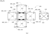
- the shell 101 still comprises panels 106 so as to surround the neutralization container 8, and the assembly system 102 comprises fixed connections 120 , that is to say intended to remain in place and to ensure a permanent connection between at least part of the panels 106.
- the fixed connections 120 are articulated, for example of the hinge type, and make it possible to obtain an unfolded planar shape corresponding at least in part to the final shape of the external shell 101 when the device 100 is in the transport state. By folding at least part of the panels 106 towards each other, the outer shell 101 closes at least in part so as to be able to contain the neutralization container 8.
- the assembly system 102 can then further comprise a locking system 121 , making it possible to hold the panels 106 against each other. More precisely, according to the realization illustrated on the Figure 9 , the panels 106 are of substantially rectangular shape. Four panels 106, called side panels, are each connected on one edge of a fifth panel 106, called upper panel 106 using a fixed connection 120. In the unfolded planar form, the side and bottom panels 106 are substantially coplanar.
- the outer shell 101 can be placed on the neutralization container 8 in the manner of a bell: by lifting the panels articulated relative to each other, the shape closes under the effect of the weight of the side panels 106 which pivot 90° under the effect of gravity around the upper panel 106, the side panels 106 coming into contact edge to edge the ones with the others. It can then be placed on top of the neutralization container 8.
- the side panels 106 are provided with pins 122 abutting against the neutralization container 8, so as to maintain a gap as seen above.
- the dimension of the gap is adjustable according to needs by dimensioning the pins 122 for this purpose.
- the locking system 109 is then activated to maintain the side panels 106 in this position.
- the upper panel 106 may include an opening 123 , so as to provide access for example to the hatch 111 on the neutralization container 8.
- a sixth panel 106 serving as a cover (on the right on the Figure 9 ) can then be attached and possibly fixed in a removable manner in order to cover the opening 123.
- the outer shell 101 covers the neutralization container 8 and the transport and treatment device 100 is then in the transport state.
- the locking system 121 is deactivated to release the four side panels 106 around the bottom panel 106.
- the side panels 106 are then returned to the flat unfolded position relative to the bottom panel 106 by rotation around the fixed hinge-type connections 120.
- the neutralization container 8 can then be removed, so that the device 100 is in the treatment state, and can be placed in the recycling installation 1.
- the locking system 121 comprises, for example, clasps, which cooperate in pairs.
- the neutralization container 8 can comprise the same arrangements as those described for the first embodiment, and in particular the hatch 111 and/or the side doors 115, accessible by removing the panel 106 acting as a cover or by unfolding at least partially the other panels 106.
- the bodies for cooperation with handling equipment comprise for example four openings 124 in the upper panel 106 allowing the insertion of forks from a handling equipment, for example of the forklift type to lift the panels 106 and place them over the container 8 like a bell.
- the forks are inserted between the outer shell 101 and the neutralization container 8, thanks to the distance maintained with the pins 122.
- the panel 106 serving as a cover may include handles, for example attached, and fixed by welding on the panel 106 acting as a cover, in order to facilitate the handling of the transport and treatment device 100.
- the outer shell 101 forming a bell of this second embodiment can be used in combination with the outer shell 101 of the first embodiment comprising the panels 106 mounted by sliding on the angles 105. This combination makes it possible in particular to increase the efficiency of the electromagnetic shielding or even to compensate for the absence of a sliding panel 106.
- a used magnet mounted in a machine when a used magnet mounted in a machine must be transported for example to be brought to the recycling installation 1, it is first collected on the site of the machine, then placed in the transport device 100 and processing, which is then put into the transport state.
- the outer shell 101 provides electromagnetic shielding, reducing or even eliminating any interference problem between the magnet and the environment, and in particular with equipment of a transport vehicle.
- the magnet is thus transported safely to the site of recycling installation 1.
- the outer shell 101 is removed, leaving the magnet in the receptacle of the neutralization container 8, which can then be passed directly into the demagnetization station 2. Direct and dangerous manipulation of the magnet is thus reduced. Security is increased.
- the level of precaution to be taken on the site of recycling installation 1 is reduced, facilitating recycling and increasing the revaluation of the magnet.
- the treatment and transport device 100 can thus be used from the collection step until the end of the demagnetization step, and in particular the demagnetization heat treatment, then be reused in a closed logistics loop.
- the materials recovered from magnets, and in particular rare earths, can be reintroduced into other processes of different transformation routes.
- the reuse of these recycled materials in a circular economy makes it possible to envisage new manufacturing and industrial applications.
- the transport and treatment device 100 is particularly suitable for implementing the recycling process in the recycling installation 1, since it makes it possible to limit dangerous handling of the magnets: a once the magnets are placed in the device 100, they remain contained there until their demagnetization in the installation 1 of recycling.
- the transport and treatment device 100 can be used independently of the recycling process and installation 1.
Landscapes
- Engineering & Computer Science (AREA)
- Power Engineering (AREA)
- Processing Of Solid Wastes (AREA)
- Powder Metallurgy (AREA)
- Manufacturing Cores, Coils, And Magnets (AREA)
Claims (14)
- Verfahren zum Recyceln mindestens eines Magneten (D) in einer Recyclinganlage (1), wobei das Verfahren einen Schritt des Entmagnetisierens des mindestens einen Magneten (D) beinhaltet, wobei das Verfahren dadurch gekennzeichnet ist, dass es vor dem Schritt des Entmagnetisierens einen Schritt des Platzierens des Magneten im Inneren eines Neutralisierungsbehälters (8) beinhaltet, wobei der genannte Neutralisierungsbehälter (8) Wände (9, 10) aufweist, die einen geschlossenen Behälter zur Aufnahme des genannten mindestens einen Magneten (D) bilden, wobei die Wände (9, 10) zumindest teilweise aus einem nichtmagnetischen metallischen Material bestehen, wobei der Magnet (D) während mindestens eines Teils des Entmagnetisierungsschritts in dem Neutralisierungsbehälter (8) enthalten ist.
- Verfahren nach Anspruch 1, wobei der Magnet (D) während mindestens eines Teils des Entmagnetisierungsschritts Teil eines Magnetblocks ist, der Elemente umfasst, die mindestens teilweise durch Bindung an den Magneten zusammengesetzt sind.
- Verfahren nach einem der vorherigen Ansprüche, wobei der Entmagnetisierungsschritt mindestens einen Erhitzungsvorgang auf eine Maximaltemperatur umfasst, die gleich oder höher als die Curie-Temperatur des mindestens einen zu entmagnetisierenden Magneten ist.
- Verfahren nach einem der vorherigen Ansprüche, wobei der Entmagnetisierungsschritt mindestens einen Pulszykliervorgang mit abklingenden elektromagnetischen Feldern beinhaltet.
- Verfahren nach einem der vorherigen Ansprüche, das nach dem Entmagnetisierungsschritt einen Schritt des Erhitzens des Magneten auf eine Temperatur unterhalb der Curie-Temperatur des Magneten beinhaltet.
- Verfahren nach einem der vorherigen Ansprüche, das nach dem Entmagnetisierungsschritt einen Schritt des Reinigens des Magneten beinhaltet.
- Verfahren nach dem vorherigen Anspruch, wobei der Reinigungsschritt eine Dislokation des Magneten umfasst.
- Verfahren nach einem der vorherigen Ansprüche für eine Vielzahl von Magneten (D), wobei der Schritt des Platzierens der mehreren Magnete (D) lose in dem Neutralisierungsbehälter (8) durchgeführt wird.
- Verfahren nach dem vorherigen Anspruch, das einen vorherigen Schritt des Sammelns mindestens eines Teils der Vielzahl von Magneten (D) in einem Zwischensammler (11) beinhaltet, wobei der Schritt des Platzierens in dem Neutralisierungsbehälter (8) einen Vorgang des Abkippens des Inhalts des Zwischensammlers in den Neutralisierungsbehälter (8) beinhaltet.
- Verfahren nach Anspruch 9, wobei eine Ausgabevorrichtung (113) an der Schnittstelle zwischen dem Zwischensammler (11) und dem Neutralisierungsbehälter (8) verwendet wird, um die Magnete abzukippen.
- Verfahren nach einem der vorherigen Ansprüche, das einen vorherigen Schritt des Sammelns und einen Schritt des Transportierens des mindestens einen Magneten (D) beinhaltet, wobei der Schritt des Sammelns das Entnehmen des mindestens einen Magneten (D) aus einer Maschine an einem Betriebsort der Maschine beinhaltet, der Transportschritt das Transportieren vom Betriebsort der Maschine zur Recyclinganlage (1) beinhaltet, wobei der Schritt des Platzierens im Neutralisierungsbehälter (8) vor dem Transportschritt durchgeführt wird, so dass der mindestens eine Magnet (D) während des Transportschritts in dem Neutralisierungsbehälter (8) enthalten ist.
- Verfahren nach einem der vorherigen Ansprüche, wobei das nichtmagnetische Material ein austenitischer rostfreier Stahl ist.
- Verfahren nach einem der vorherigen Ansprüche, wobei der mindestens eine Magnet ein Hochleistungsmagnet ist.
- Recyclinganlage (1) für mindestens einen Magneten (D) zur Durchführung des Recyclingverfahrens nach einem der vorherigen Ansprüche, die mindestens eine Entmagnetisierungsstation (2) und mindestens eine Station (7) zum Platzieren in einem Neutralisierungsbehälter (8) umfasst, wobei der genannte Neutralisierungsbehälter Wände (9, 10) aufweist, die einen geschlossenen Behälter für den genannten mindestens einen Magneten (D) bilden, wobei die Wände (9, 10) zumindest teilweise aus einem nichtmagnetischen metallischen Material bestehen.
Applications Claiming Priority (1)
| Application Number | Priority Date | Filing Date | Title |
|---|---|---|---|
| FR2110290A FR3127626B1 (fr) | 2021-09-29 | 2021-09-29 | Procédé de recyclage d’au moins un aimant et installation pour la mise en œuvre d’un tel procédé |
Publications (3)
| Publication Number | Publication Date |
|---|---|
| EP4160628A1 EP4160628A1 (de) | 2023-04-05 |
| EP4160628C0 EP4160628C0 (de) | 2024-06-05 |
| EP4160628B1 true EP4160628B1 (de) | 2024-06-05 |
Family
ID=78332959
Family Applications (1)
| Application Number | Title | Priority Date | Filing Date |
|---|---|---|---|
| EP22198180.6A Active EP4160628B1 (de) | 2021-09-29 | 2022-09-27 | Verfahren zum recycling von mindestens einem magneten und anlage zur durchführung eines solchen verfahrens |
Country Status (2)
| Country | Link |
|---|---|
| EP (1) | EP4160628B1 (de) |
| FR (1) | FR3127626B1 (de) |
Families Citing this family (1)
| Publication number | Priority date | Publication date | Assignee | Title |
|---|---|---|---|---|
| EP4447297A1 (de) * | 2023-04-11 | 2024-10-16 | Siemens Gamesa Renewable Energy A/S | System und verfahren zur verarbeitung von magnetelementen einer windturbinengeneratorkomponente |
Family Cites Families (5)
| Publication number | Priority date | Publication date | Assignee | Title |
|---|---|---|---|---|
| CH474821A (de) * | 1967-02-28 | 1969-06-30 | List Heinrich | Gerät zum Entmagnetisieren von Gegenständen wie Kleinteilen, Werkzeugen und dergleichen |
| GB2486175A (en) | 2010-12-02 | 2012-06-13 | Univ Birmingham | Separating rare earth magnetic materials from electronic devices |
| JP5110181B2 (ja) * | 2011-02-22 | 2012-12-26 | 三菱マテリアル株式会社 | 希土類磁石素材回収システム |
| WO2014205002A2 (en) | 2013-06-17 | 2014-12-24 | Miha Zakotnik | Magnet recycling to create nd-fe-b magnets with improved or restored magnetic performance |
| WO2017079183A1 (en) * | 2015-11-06 | 2017-05-11 | Ut-Battelle, Llc | System and method for the recycling of rare earth magnets |
-
2021
- 2021-09-29 FR FR2110290A patent/FR3127626B1/fr active Active
-
2022
- 2022-09-27 EP EP22198180.6A patent/EP4160628B1/de active Active
Also Published As
| Publication number | Publication date |
|---|---|
| FR3127626B1 (fr) | 2023-09-29 |
| FR3127626A1 (fr) | 2023-03-31 |
| EP4160628C0 (de) | 2024-06-05 |
| EP4160628A1 (de) | 2023-04-05 |
Similar Documents
| Publication | Publication Date | Title |
|---|---|---|
| EP3328559B1 (de) | Einheit zur reinigung von platten zur generativen fertigung | |
| EP4160628A1 (de) | Verfahren zum recycling von mindestens einem magneten und anlage zur durchführung eines solchen verfahrens | |
| FR3039437A1 (fr) | Procede de nettoyage a sec de plateaux de fabrication additive | |
| FR3039436A1 (fr) | Dispositif de nettoyage a sec d’un plateau de fabrication additive | |
| EP3059191B1 (de) | Maschine und verfahren zur förderung von artikeln | |
| FR3058338A1 (fr) | Dispositif combine de transvasement et de tamisage de poudre de fabrication additive | |
| FR2917752A1 (fr) | Procede de traitement thermique de pieces de fonderie mettant en oeuvre une trempe a l'air et systeme pour la mise en oeuvre du procede | |
| JP5800636B2 (ja) | 放射性金属廃棄物処理装置 | |
| CA3047899C (fr) | Palettisation robotisee | |
| EP4159641A1 (de) | Vorrichtung zum transportieren und bearbeiten mindestens eines magneten | |
| EP3700695B1 (de) | Verfahren und vorrichtung zum giessen von metallischem glas | |
| JP5344304B2 (ja) | トラフ揺動式ショットブラスト装置及びトラフ揺動式ショットブラスト処理方法 | |
| EP0737755B1 (de) | Verfahren und Vorrichtung zur Wärmebehandlung von Werkstücken | |
| FR2463643A1 (fr) | Procede et dispositif pour la recuperation selective des conteneurs metalliques | |
| EP2895411B1 (de) | Anordnung zur entladung gestapelter lasten | |
| EP1663826B1 (de) | Handhabungsvorrichtung für kästen und dergleichen | |
| BE1015579A6 (fr) | Machine de triage automatique pour dechets recyclables. | |
| EP0599727A1 (de) | Verfahren und Vorrichtung zur Behandlung von aktiven Elementen zur Entsorgung | |
| EP2033714B1 (de) | Verfahren und Vorrichtung zum Recycling von Tintenpatronen | |
| CA3229207A1 (fr) | Ligne de refusion de scrap en alliage d'aluminium eco-responsable | |
| EP4546373A1 (de) | Verpackung und verfahren zum transport von radioaktives material enthaltenden fässern | |
| FR2770428A1 (fr) | Installation automatisee pour le degrappage de pieces metalliques en sortie de fonderie | |
| EP3003405B1 (de) | Vorrichtung zur behandlung von gegenständen mittels elektronischen beschusses | |
| CA2213692A1 (fr) | Methode et appareil pour eteindre et refroidir un residu chaud sortant d'un four de traitement des crasses | |
| EP0677476A1 (de) | Vorrichtung zum Transferieren und Fördern von länglichen Teilen |
Legal Events
| Date | Code | Title | Description |
|---|---|---|---|
| PUAI | Public reference made under article 153(3) epc to a published international application that has entered the european phase |
Free format text: ORIGINAL CODE: 0009012 |
|
| STAA | Information on the status of an ep patent application or granted ep patent |
Free format text: STATUS: THE APPLICATION HAS BEEN PUBLISHED |
|
| AK | Designated contracting states |
Kind code of ref document: A1 Designated state(s): AL AT BE BG CH CY CZ DE DK EE ES FI FR GB GR HR HU IE IS IT LI LT LU LV MC MK MT NL NO PL PT RO RS SE SI SK SM TR |
|
| STAA | Information on the status of an ep patent application or granted ep patent |
Free format text: STATUS: REQUEST FOR EXAMINATION WAS MADE |
|
| 17P | Request for examination filed |
Effective date: 20230921 |
|
| RBV | Designated contracting states (corrected) |
Designated state(s): AL AT BE BG CH CY CZ DE DK EE ES FI FR GB GR HR HU IE IS IT LI LT LU LV MC MK MT NL NO PL PT RO RS SE SI SK SM TR |
|
| GRAP | Despatch of communication of intention to grant a patent |
Free format text: ORIGINAL CODE: EPIDOSNIGR1 |
|
| STAA | Information on the status of an ep patent application or granted ep patent |
Free format text: STATUS: GRANT OF PATENT IS INTENDED |
|
| INTG | Intention to grant announced |
Effective date: 20240221 |
|
| GRAS | Grant fee paid |
Free format text: ORIGINAL CODE: EPIDOSNIGR3 |
|
| GRAA | (expected) grant |
Free format text: ORIGINAL CODE: 0009210 |
|
| STAA | Information on the status of an ep patent application or granted ep patent |
Free format text: STATUS: THE PATENT HAS BEEN GRANTED |
|
| AK | Designated contracting states |
Kind code of ref document: B1 Designated state(s): AL AT BE BG CH CY CZ DE DK EE ES FI FR GB GR HR HU IE IS IT LI LT LU LV MC MK MT NL NO PL PT RO RS SE SI SK SM TR |
|
| REG | Reference to a national code |
Ref country code: CH Ref legal event code: EP |
|
| REG | Reference to a national code |
Ref country code: DE Ref legal event code: R096 Ref document number: 602022003794 Country of ref document: DE |
|
| REG | Reference to a national code |
Ref country code: IE Ref legal event code: FG4D Free format text: LANGUAGE OF EP DOCUMENT: FRENCH |
|
| U01 | Request for unitary effect filed |
Effective date: 20240617 |
|
| U07 | Unitary effect registered |
Designated state(s): AT BE BG DE DK EE FI FR IT LT LU LV MT NL PT SE SI Effective date: 20240705 |
|
| U20 | Renewal fee for the european patent with unitary effect paid |
Year of fee payment: 3 Effective date: 20240722 |
|
| PG25 | Lapsed in a contracting state [announced via postgrant information from national office to epo] |
Ref country code: HR Free format text: LAPSE BECAUSE OF FAILURE TO SUBMIT A TRANSLATION OF THE DESCRIPTION OR TO PAY THE FEE WITHIN THE PRESCRIBED TIME-LIMIT Effective date: 20240605 |
|
| PG25 | Lapsed in a contracting state [announced via postgrant information from national office to epo] |
Ref country code: GR Free format text: LAPSE BECAUSE OF FAILURE TO SUBMIT A TRANSLATION OF THE DESCRIPTION OR TO PAY THE FEE WITHIN THE PRESCRIBED TIME-LIMIT Effective date: 20240906 |
|
| PG25 | Lapsed in a contracting state [announced via postgrant information from national office to epo] |
Ref country code: ES Free format text: LAPSE BECAUSE OF FAILURE TO SUBMIT A TRANSLATION OF THE DESCRIPTION OR TO PAY THE FEE WITHIN THE PRESCRIBED TIME-LIMIT Effective date: 20240605 |
|
| PG25 | Lapsed in a contracting state [announced via postgrant information from national office to epo] |
Ref country code: NO Free format text: LAPSE BECAUSE OF FAILURE TO SUBMIT A TRANSLATION OF THE DESCRIPTION OR TO PAY THE FEE WITHIN THE PRESCRIBED TIME-LIMIT Effective date: 20240905 Ref country code: HR Free format text: LAPSE BECAUSE OF FAILURE TO SUBMIT A TRANSLATION OF THE DESCRIPTION OR TO PAY THE FEE WITHIN THE PRESCRIBED TIME-LIMIT Effective date: 20240605 Ref country code: GR Free format text: LAPSE BECAUSE OF FAILURE TO SUBMIT A TRANSLATION OF THE DESCRIPTION OR TO PAY THE FEE WITHIN THE PRESCRIBED TIME-LIMIT Effective date: 20240906 Ref country code: ES Free format text: LAPSE BECAUSE OF FAILURE TO SUBMIT A TRANSLATION OF THE DESCRIPTION OR TO PAY THE FEE WITHIN THE PRESCRIBED TIME-LIMIT Effective date: 20240605 Ref country code: RS Free format text: LAPSE BECAUSE OF FAILURE TO SUBMIT A TRANSLATION OF THE DESCRIPTION OR TO PAY THE FEE WITHIN THE PRESCRIBED TIME-LIMIT Effective date: 20240905 |
|
| PG25 | Lapsed in a contracting state [announced via postgrant information from national office to epo] |
Ref country code: PL Free format text: LAPSE BECAUSE OF FAILURE TO SUBMIT A TRANSLATION OF THE DESCRIPTION OR TO PAY THE FEE WITHIN THE PRESCRIBED TIME-LIMIT Effective date: 20240605 |
|
| PG25 | Lapsed in a contracting state [announced via postgrant information from national office to epo] |
Ref country code: IS Free format text: LAPSE BECAUSE OF FAILURE TO SUBMIT A TRANSLATION OF THE DESCRIPTION OR TO PAY THE FEE WITHIN THE PRESCRIBED TIME-LIMIT Effective date: 20241005 |
|
| PG25 | Lapsed in a contracting state [announced via postgrant information from national office to epo] |
Ref country code: CZ Free format text: LAPSE BECAUSE OF FAILURE TO SUBMIT A TRANSLATION OF THE DESCRIPTION OR TO PAY THE FEE WITHIN THE PRESCRIBED TIME-LIMIT Effective date: 20240605 |
|
| PG25 | Lapsed in a contracting state [announced via postgrant information from national office to epo] |
Ref country code: RO Free format text: LAPSE BECAUSE OF FAILURE TO SUBMIT A TRANSLATION OF THE DESCRIPTION OR TO PAY THE FEE WITHIN THE PRESCRIBED TIME-LIMIT Effective date: 20240605 Ref country code: SK Free format text: LAPSE BECAUSE OF FAILURE TO SUBMIT A TRANSLATION OF THE DESCRIPTION OR TO PAY THE FEE WITHIN THE PRESCRIBED TIME-LIMIT Effective date: 20240605 |
|
| PG25 | Lapsed in a contracting state [announced via postgrant information from national office to epo] |
Ref country code: SM Free format text: LAPSE BECAUSE OF FAILURE TO SUBMIT A TRANSLATION OF THE DESCRIPTION OR TO PAY THE FEE WITHIN THE PRESCRIBED TIME-LIMIT Effective date: 20240605 |
|
| PG25 | Lapsed in a contracting state [announced via postgrant information from national office to epo] |
Ref country code: SM Free format text: LAPSE BECAUSE OF FAILURE TO SUBMIT A TRANSLATION OF THE DESCRIPTION OR TO PAY THE FEE WITHIN THE PRESCRIBED TIME-LIMIT Effective date: 20240605 Ref country code: SK Free format text: LAPSE BECAUSE OF FAILURE TO SUBMIT A TRANSLATION OF THE DESCRIPTION OR TO PAY THE FEE WITHIN THE PRESCRIBED TIME-LIMIT Effective date: 20240605 Ref country code: RO Free format text: LAPSE BECAUSE OF FAILURE TO SUBMIT A TRANSLATION OF THE DESCRIPTION OR TO PAY THE FEE WITHIN THE PRESCRIBED TIME-LIMIT Effective date: 20240605 Ref country code: PL Free format text: LAPSE BECAUSE OF FAILURE TO SUBMIT A TRANSLATION OF THE DESCRIPTION OR TO PAY THE FEE WITHIN THE PRESCRIBED TIME-LIMIT Effective date: 20240605 Ref country code: IS Free format text: LAPSE BECAUSE OF FAILURE TO SUBMIT A TRANSLATION OF THE DESCRIPTION OR TO PAY THE FEE WITHIN THE PRESCRIBED TIME-LIMIT Effective date: 20241005 Ref country code: CZ Free format text: LAPSE BECAUSE OF FAILURE TO SUBMIT A TRANSLATION OF THE DESCRIPTION OR TO PAY THE FEE WITHIN THE PRESCRIBED TIME-LIMIT Effective date: 20240605 |
|
| PLBE | No opposition filed within time limit |
Free format text: ORIGINAL CODE: 0009261 |
|
| STAA | Information on the status of an ep patent application or granted ep patent |
Free format text: STATUS: NO OPPOSITION FILED WITHIN TIME LIMIT |
|
| PG25 | Lapsed in a contracting state [announced via postgrant information from national office to epo] |
Ref country code: MC Free format text: LAPSE BECAUSE OF FAILURE TO SUBMIT A TRANSLATION OF THE DESCRIPTION OR TO PAY THE FEE WITHIN THE PRESCRIBED TIME-LIMIT Effective date: 20240605 |
|
| 26N | No opposition filed |
Effective date: 20250306 |
|
| PG25 | Lapsed in a contracting state [announced via postgrant information from national office to epo] |
Ref country code: IE Free format text: LAPSE BECAUSE OF NON-PAYMENT OF DUE FEES Effective date: 20240927 |
|
| U20 | Renewal fee for the european patent with unitary effect paid |
Year of fee payment: 4 Effective date: 20250721 |
|
| PG25 | Lapsed in a contracting state [announced via postgrant information from national office to epo] |
Ref country code: CY Free format text: LAPSE BECAUSE OF FAILURE TO SUBMIT A TRANSLATION OF THE DESCRIPTION OR TO PAY THE FEE WITHIN THE PRESCRIBED TIME-LIMIT; INVALID AB INITIO Effective date: 20220927 |
|
| PG25 | Lapsed in a contracting state [announced via postgrant information from national office to epo] |
Ref country code: HU Free format text: LAPSE BECAUSE OF FAILURE TO SUBMIT A TRANSLATION OF THE DESCRIPTION OR TO PAY THE FEE WITHIN THE PRESCRIBED TIME-LIMIT; INVALID AB INITIO Effective date: 20220927 |
|
| REG | Reference to a national code |
Ref country code: CH Ref legal event code: H13 Free format text: ST27 STATUS EVENT CODE: U-0-0-H10-H13 (AS PROVIDED BY THE NATIONAL OFFICE) Effective date: 20260504 |