EP4160356A1 - Electronic device for supplying power, and operating method therefor - Google Patents
Electronic device for supplying power, and operating method therefor Download PDFInfo
- Publication number
- EP4160356A1 EP4160356A1 EP21850774.7A EP21850774A EP4160356A1 EP 4160356 A1 EP4160356 A1 EP 4160356A1 EP 21850774 A EP21850774 A EP 21850774A EP 4160356 A1 EP4160356 A1 EP 4160356A1
- Authority
- EP
- European Patent Office
- Prior art keywords
- electronic device
- current value
- external electronic
- processor
- power
- Prior art date
- Legal status (The legal status is an assumption and is not a legal conclusion. Google has not performed a legal analysis and makes no representation as to the accuracy of the status listed.)
- Pending
Links
Images




Classifications
-
- G—PHYSICS
- G06—COMPUTING OR CALCULATING; COUNTING
- G06F—ELECTRIC DIGITAL DATA PROCESSING
- G06F1/00—Details not covered by groups G06F3/00 - G06F13/00 and G06F21/00
- G06F1/26—Power supply means, e.g. regulation thereof
- G06F1/266—Arrangements to supply power to external peripherals either directly from the computer or under computer control, e.g. supply of power through the communication port, computer controlled power-strips
-
- G—PHYSICS
- G01—MEASURING; TESTING
- G01R—MEASURING ELECTRIC VARIABLES; MEASURING MAGNETIC VARIABLES
- G01R31/00—Arrangements for testing electric properties; Arrangements for locating electric faults; Arrangements for electrical testing characterised by what is being tested not provided for elsewhere
- G01R31/36—Arrangements for testing, measuring or monitoring the electrical condition of accumulators or electric batteries, e.g. capacity or state of charge [SoC]
- G01R31/382—Arrangements for monitoring battery or accumulator variables, e.g. SoC
-
- G—PHYSICS
- G06—COMPUTING OR CALCULATING; COUNTING
- G06F—ELECTRIC DIGITAL DATA PROCESSING
- G06F1/00—Details not covered by groups G06F3/00 - G06F13/00 and G06F21/00
- G06F1/26—Power supply means, e.g. regulation thereof
- G06F1/32—Means for saving power
- G06F1/3203—Power management, i.e. event-based initiation of a power-saving mode
- G06F1/3206—Monitoring of events, devices or parameters that trigger a change in power modality
- G06F1/3212—Monitoring battery levels, e.g. power saving mode being initiated when battery voltage goes below a certain level
-
- H—ELECTRICITY
- H02—GENERATION; CONVERSION OR DISTRIBUTION OF ELECTRIC POWER
- H02J—ELECTRIC POWER NETWORKS; CIRCUIT ARRANGEMENTS OR SYSTEMS FOR SUPPLYING OR DISTRIBUTING ELECTRIC POWER; SYSTEMS FOR STORING ELECTRIC ENERGY
- H02J7/00—Circuit arrangements for charging or discharging batteries or for supplying loads from batteries
- H02J7/40—Circuit arrangements for charging or discharging batteries or for supplying loads from batteries characterised by the exchange of charge or discharge related data
- H02J7/44—Circuit arrangements for charging or discharging batteries or for supplying loads from batteries characterised by the exchange of charge or discharge related data between battery management systems and power sources
-
- H—ELECTRICITY
- H02—GENERATION; CONVERSION OR DISTRIBUTION OF ELECTRIC POWER
- H02J—ELECTRIC POWER NETWORKS; CIRCUIT ARRANGEMENTS OR SYSTEMS FOR SUPPLYING OR DISTRIBUTING ELECTRIC POWER; SYSTEMS FOR STORING ELECTRIC ENERGY
- H02J7/00—Circuit arrangements for charging or discharging batteries or for supplying loads from batteries
- H02J7/90—Regulation of charging or discharging current or voltage
- H02J7/971—Regulation of charging or discharging current or voltage the charge cycle being controlled or terminated in response to non-electric parameters
- H02J7/975—Regulation of charging or discharging current or voltage the charge cycle being controlled or terminated in response to non-electric parameters in response to temperature
- H02J7/977—Regulation of charging or discharging current or voltage the charge cycle being controlled or terminated in response to non-electric parameters in response to temperature of the battery
-
- H—ELECTRICITY
- H04—ELECTRIC COMMUNICATION TECHNIQUE
- H04M—TELEPHONIC COMMUNICATION
- H04M1/00—Substation equipment, e.g. for use by subscribers
- H04M1/72—Mobile telephones; Cordless telephones, i.e. devices for establishing wireless links to base stations without route selection
- H04M1/724—User interfaces specially adapted for cordless or mobile telephones
- H04M1/72403—User interfaces specially adapted for cordless or mobile telephones with means for local support of applications that increase the functionality
- H04M1/72409—User interfaces specially adapted for cordless or mobile telephones with means for local support of applications that increase the functionality by interfacing with external accessories
Definitions
- the disclosure relates to an electronic device for supplying power and an operation method thereof.
- An electronic device may provide power to an external electronic device using wired and wireless interfaces.
- Such an electronic device may include a power management integrated circuit (PMIC) for managing power supplied to the external electronic device.
- PMIC power management integrated circuit
- An electronic device may provide power to an external electronic device, based on a protocol related to a wired interface.
- the external electronic device may fail to receive the necessary amount of power. Accordingly, the external electronic device may fail to operate.
- An electronic device may include: a battery; a connector including multiple pins; and at least one processor, wherein the at least one processor is configured to: identify an external electronic device electrically connected through the connector; identify, among at least two supportable current values, a current value of power to be supplied to the external electronic device; and supply, based on the identified current value, power of the battery to the external electronic device through the connector.
- a method of operating an electronic device may include: identifying an external electronic device electrically connected through a connector of the electronic device; identifying, among at least two supportable current values, a current value of power to be supplied to the external electronic device; and supplying, based on the identified current value, power of a battery of the electronic device to the external electronic device through the connector.
- An electronic device and an operation method thereof may provide necessary power to an external electronic device.
- Fig. 1 is a block diagram illustrating an example electronic device 101 in a network environment 100 according to various embodiments.
- the electronic device 101 in the network environment 100 may communicate with an electronic device 102 via a first network 198 (e.g., a short-range wireless communication network), or an electronic device 104 or a server 108 via a second network 199 (e.g., a long-range wireless communication network).
- the electronic device 101 may communicate with the electronic device 104 via the server 108.
- the electronic device 101 may include a processor 120, memory 130, an input device 150, a sound output device 155, a display device 160, an audio module 170, a sensor module 176, an interface 177, a haptic module 179, a camera module 180, a power management module 188, a battery 189, a communication module 190, a subscriber identification module (SIM) 196, or an antenna module 197.
- at least one (e.g., the display device 160 or the camera module 180) of the components may be omitted from the electronic device 101, or one or more other components may be added in the electronic device 101.
- some of the components may be implemented as single integrated circuitry.
- the sensor module 176 e.g., a fingerprint sensor, an iris sensor, or an illuminance sensor
- the display device 160 e.g., a display
- an haptic module 179 e.g., a camera module 180
- a power management module 188 e.g., the display
- the processor 120 may execute, for example, software (e.g., a program 140) to control at least one other component (e.g., a hardware or software component) of the electronic device 101 coupled with the processor 120, and may perform various data processing or computation. According to an embodiment, as at least part of the data processing or computation, the processor 120 may load a command or data received from another component (e.g., the sensor module 176 or the communication module 190) in volatile memory 132, process the command or the data stored in the volatile memory 132, and store resulting data in non-volatile memory 134.
- software e.g., a program 140
- the processor 120 may load a command or data received from another component (e.g., the sensor module 176 or the communication module 190) in volatile memory 132, process the command or the data stored in the volatile memory 132, and store resulting data in non-volatile memory 134.
- the processor 120 may include a main processor 121 (e.g., a central processing unit (CPU) or an application processor (AP)), and an auxiliary processor 123 (e.g., a graphics processing unit (GPU), an image signal processor (ISP), a sensor hub processor, or a communication processor (CP)) that is operable independently from, or in conjunction with, the main processor 121.
- auxiliary processor 123 may be adapted to consume less power than the main processor 121, or to be specific to a specified function.
- the auxiliary processor 123 may be implemented as separate from, or as part of the main processor 121.
- the auxiliary processor 123 may control at least some of functions or states related to at least one component (e.g., the display device 160, the sensor module 176, or the communication module 190) among the components of the electronic device 101, instead of the main processor 121 while the main processor 121 is in an inactive (e.g., sleep) state, or together with the main processor 121 while the main processor 121 is in an active state (e.g., executing an application).
- the auxiliary processor 123 e.g., an image signal processor or a communication processor
- the memory 130 may store various data used by at least one component (e.g., the processor 120 or the sensor module 176) of the electronic device 101.
- the various data may include, for example, software (e.g., the program 140) and input data or output data for a command related thereto.
- the memory 130 may include the volatile memory 132 or the non-volatile memory 134.
- the program 140 may be stored in the memory 130 as software, and may include, for example, an operating system (OS) 142, middleware 144, or an application 146.
- OS operating system
- middleware middleware
- application application
- the input device 150 may receive a command or data to be used by other component (e.g., the processor 120) of the electronic device 101, from the outside (e.g., a user) of the electronic device 101.
- the input device 150 may include, for example, a microphone, a mouse, a keyboard, or a digital pen (e.g., a stylus pen).
- the sound output device 155 may output sound signals to the outside of the electronic device 101.
- the sound output device 155 may include, for example, a speaker or a receiver.
- the speaker may be used for general purposes, such as playing multimedia or playing record, and the receiver may be used for an incoming calls. According to an embodiment, the receiver may be implemented as separate from, or as part of the speaker.
- the display device 160 may visually provide information to the outside (e.g., a user) of the electronic device 101.
- the display device 160 may include, for example, a display, a hologram device, or a projector and control circuitry to control a corresponding one of the display, hologram device, and projector.
- the display device 160 may include touch circuitry adapted to detect a touch, or sensor circuitry (e.g., a pressure sensor) adapted to measure the intensity of force incurred by the touch.
- the audio module 170 may convert a sound into an electrical signal and vice versa. According to an embodiment, the audio module 170 may obtain the sound via the input device 150, or output the sound via the sound output device 155 or a headphone of an external electronic device (e.g., an electronic device 102) directly (e.g., wiredly) or wirelessly coupled with the electronic device 101.
- an external electronic device e.g., an electronic device 102
- directly e.g., wiredly
- wirelessly e.g., wirelessly
- the sensor module 176 may detect an operational state (e.g., power or temperature) of the electronic device 101 or an environmental state (e.g., a state of a user) external to the electronic device 101, and then generate an electrical signal or data value corresponding to the detected state.
- the sensor module 176 may include, for example, a gesture sensor, a gyro sensor, an atmospheric pressure sensor, a magnetic sensor, an acceleration sensor, a grip sensor, a proximity sensor, a color sensor, an infrared (IR) sensor, a biometric sensor, a temperature sensor, a humidity sensor, or an illuminance sensor.
- the interface 177 may support one or more specified protocols to be used for the electronic device 101 to be coupled with the external electronic device (e.g., the electronic device 102) directly (e.g., wiredly) or wirelessly.
- the interface 177 may include, for example, a high definition multimedia interface (HDMI), a universal serial bus (USB) interface, a secure digital (SD) card interface, or an audio interface.
- HDMI high definition multimedia interface
- USB universal serial bus
- SD secure digital
- a connecting terminal 178 may include a connector via which the electronic device 101 may be physically connected with the external electronic device (e.g., the electronic device 102).
- the connecting terminal 178 may include, for example, a HDMI connector, a USB connector, a SD card connector, or an audio connector (e.g., a headphone connector).
- the haptic module 179 may convert an electrical signal into a mechanical stimulus (e.g., a vibration or a movement) or electrical stimulus which may be recognized by a user via his tactile sensation or kinesthetic sensation.
- the haptic module 179 may include, for example, a motor, a piezoelectric element, or an electric stimulator.
- the camera module 180 may capture a still image or moving images.
- the camera module 180 may include one or more lenses, image sensors, image signal processors, or flashes.
- the power management module 188 may manage power supplied to the electronic device 101.
- the power management module 188 may be implemented as at least part of, for example, a power management integrated circuit (PMIC).
- PMIC power management integrated circuit
- the battery 189 may supply power to at least one component of the electronic device 101.
- the battery 189 may include, for example, a primary cell which is not rechargeable, a secondary cell which is rechargeable, or a fuel cell.
- the communication module 190 may support establishing a direct (e.g., wired) communication channel or a wireless communication channel between the electronic device 101 and the external electronic device (e.g., the electronic device 102, the electronic device 104, or the server 108) and performing communication via the established communication channel.
- the communication module 190 may include one or more communication processors that are operable independently from the processor 120 (e.g., the application processor (AP)) and supports a direct (e.g., wired) communication or a wireless communication.
- AP application processor
- the communication module 190 may include a wireless communication module 192 (e.g., a cellular communication module, a short-range wireless communication module, or a global navigation satellite system (GNSS) communication module) or a wired communication module 194 (e.g., a local area network (LAN) communication module or a power line communication (PLC) module).
- a wireless communication module 192 e.g., a cellular communication module, a short-range wireless communication module, or a global navigation satellite system (GNSS) communication module
- GNSS global navigation satellite system
- wired communication module 194 e.g., a local area network (LAN) communication module or a power line communication (PLC) module.
- LAN local area network
- PLC power line communication
- a corresponding one of these communication modules may communicate with the external electronic device via the first network 198 (e.g., a short-range communication network, such as Bluetooth TM , wireless-fidelity (Wi-Fi) direct, or infrared data association (IrDA)) or the second network 199 (e.g., a long-range communication network, such as a cellular network, the Internet, or a computer network (e.g., LAN or wide area network (WAN)).
- the first network 198 e.g., a short-range communication network, such as Bluetooth TM , wireless-fidelity (Wi-Fi) direct, or infrared data association (IrDA)
- the second network 199 e.g., a long-range communication network, such as a cellular network, the Internet, or a computer network (e.g., LAN or wide area network (WAN)
- These various types of communication modules may be implemented as a single component (e.g., a single chip), or may be implemented as multi
- the wireless communication module 192 may identify and authenticate the electronic device 101 in a communication network, such as the first network 198 or the second network 199, using subscriber information (e.g., international mobile subscriber identity (IMSI)) stored in the subscriber identification module 196.
- subscriber information e.g., international mobile subscriber identity (IMSI)
- the antenna module 197 may transmit or receive a signal or power to or from the outside (e.g., the external electronic device) of the electronic device 101.
- the antenna module 197 may include an antenna including a radiating element composed of a conductive material or a conductive pattern formed in or on a substrate (e.g., PCB).
- the antenna module 197 may include a plurality of antennas. In such a case, at least one antenna appropriate for a communication scheme used in the communication network, such as the first network 198 or the second network 199, may be selected, for example, by the communication module 190 (e.g., the wireless communication module 192) from the plurality of antennas.
- the signal or the power may then be transmitted or received between the communication module 190 and the external electronic device via the selected at least one antenna.
- another component e.g., a radio frequency integrated circuit (RFIC)
- RFIC radio frequency integrated circuit
- At least some of the above-described components may be coupled mutually and communicate signals (e.g., commands or data) therebetween via an inter-peripheral communication scheme (e.g., a bus, general purpose input and output (GPIO), serial peripheral interface (SPI), or mobile industry processor interface (MIPI)).
- an inter-peripheral communication scheme e.g., a bus, general purpose input and output (GPIO), serial peripheral interface (SPI), or mobile industry processor interface (MIPI)
- commands or data may be transmitted or received between the electronic device 101 and the external electronic device 104 via the server 108 coupled with the second network 199.
- Each of the electronic devices 102 and 104 may be a device of a same type as, or a different type, from the electronic device 101.
- all or some of operations to be executed at the electronic device 101 may be executed at one or more of the external electronic devices 102, 104, or 108. For example, if the electronic device 101 should perform a function or a service automatically, or in response to a request from a user or another device, the electronic device 101, instead of, or in addition to, executing the function or the service, may request the one or more external electronic devices to perform at least part of the function or the service.
- the one or more external electronic devices receiving the request may perform the at least part of the function or the service requested, or an additional function or an additional service related to the request, and transfer an outcome of the performing to the electronic device 101.
- the electronic device 101 may provide the outcome, with or without further processing of the outcome, as at least part of a reply to the request.
- a cloud computing, distributed computing, or client-server computing technology may be used, for example.
- Fig. 2 is a block diagram 200 illustrating an example of the program 140 according to various embodiments.
- the program 140 may include an operating system (OS) 142 to control one or more resources of the electronic device 101, middleware 144, or an application 146 executable in the OS 142.
- the OS 142 may include, for example, Android TM , iOS TM , Windows TM , Symbian TM , Tizen TM , or Bada TM .
- At least part of the program 140 may be pre-loaded on the electronic device 101 during manufacture, or may be downloaded from or updated by an external electronic device (e.g., the electronic device 102 or 104, or the server 108) during use by a user.
- an external electronic device e.g., the electronic device 102 or 104, or the server 108
- the OS 142 may control management (e.g., allocating or deallocation) of one or more system resources (e.g., process, memory, or power source) of the electronic device 101.
- the OS 142 may include one or more driver programs to drive other hardware devices of the electronic device 101, for example, the input device 150, the sound output device 155, the display device 160, the audio module 170, the sensor module 176, the interface 177, the haptic module 179, the camera module 180, the power management module 188, the battery 189, the communication module 190, the subscriber identification module 196, or the antenna module 197.
- the middleware 144 may provide various functions to the application 146 such that a function or information provided from one or more resources of the electronic device 101 may be used by the application 146.
- the middleware 144 may include, for example, an application manager 201, a window manager 203, a multimedia manager 205, a resource manager 207, a power manager 209, a database manager 211, a package manager 213, a connectivity manager 215, a notification manager 217, a location manager 219, a graphic manager 221, a security manager 223, a telephony manager 225, and/or a voice recognition manager 227.
- the application manager 201 may manage the life cycle of the application 146.
- the window manager 203 may manage one or more graphical user interface (GUI) resources that are used on a screen.
- the multimedia manager 205 may identify one or more formats to be used to play media files, and may encode or decode a corresponding one of the media files using a codec appropriate for a corresponding format selected from the one or more formats.
- the resource manager 207 may manage the source code of the application 146 or a memory space of the memory 130.
- the power manager 209 may manage the capacity, temperature, or power of the battery 189, and determine or provide related information to be used for the operation of the electronic device 101 based at least in part on corresponding information of the capacity, temperature, or power of the battery 189.
- the power manager 209 may interwork with a basic input/output system (BIOS) (not shown) of the electronic device 101.
- BIOS basic input/output system
- the database manager 211 may generate, search, or change a database to be used by the application 146.
- the package manager 213, for example, may manage installation or update of an application that is distributed in the form of a package file.
- the connectivity manager 215, for example, may manage a wireless connection or a direct connection between the electronic device 101 and the external electronic device.
- the notification manager 217 for example, may provide a function to notify a user of an occurrence of a specified event (e.g., an incoming call, message, or alert).
- the location manager 219 for example, may manage locational information on the electronic device 101.
- the graphic manager 221, for example, may manage one or more graphic effects to be offered to a user or a user interface related to the one or more graphic effects.
- the security manager 223, for example, may provide system security or user authentication.
- the telephony manager 225 for example, may manage a voice call function or a video call function provided by the electronic device 101.
- the voice recognition manager 227 may transmit a user's voice data to the server 108, and receive, from the server 108, a command corresponding to a function to be executed on the electronic device 101 based at least in part on the voice data, or text data converted based at least in part on the voice data.
- the middleware 244 may dynamically delete some existing components or add new components.
- at least part of the middleware 144 may be included as part of the OS 142 or may be implemented as another software separate from the OS 142.
- the application 146 may include, for example, a home 251, dialer 253, short message service (SMS)/multimedia messaging service (MMS) 255, instant message (IM) 257, browser 259, camera 261, alarm 263, contact 265, voice recognition 267, email 269, calendar 271, media player 273, album 275, watch 277, health 279 (e.g., for measuring the degree of workout or biometric information, such as blood sugar), and/or environmental information 281 (e.g., for measuring air pressure, humidity, or temperature information) application.
- the application 146 may further include an information exchanging application (not shown) that is capable of supporting information exchange between the electronic device 101 and the external electronic device.
- the information exchange application may include a notification relay application adapted to transfer designated information (e.g., a call, message, or alert) to the external electronic device or a device management application adapted to manage the external electronic device.
- the notification relay application may transfer notification information corresponding to an occurrence of a specified event (e.g., receipt of an email) at another application (e.g., the email application 269) of the electronic device 101 to the external electronic device. Additionally or alternatively, the notification relay application may receive notification information from the external electronic device and provide the notification information to a user of the electronic device 101.
- the device management application may control the power (e.g., turn-on or turn-off) or the function (e.g., adjustment of brightness, resolution, or focus) of the external electronic device or some component thereof (e.g., a display device or a camera module of the external electronic device).
- the device management application additionally or alternatively, may support installation, delete, or update of an application running on the external electronic device.
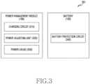
- Fig. 3 is a block diagram 300 illustrating an example of a power management module 188 and the battery 189 according to various embodiments.
- the power management module 188 may include charging circuit including circuitry 310, a power adjusting unit (e.g., including power adjusting circuitry) 320, and/or a power gauge 330.
- the charging circuitry 310 may charge the battery 189 using power supplied from an external power source outside the electronic device 101.
- the charging circuitry 310 may select a charging scheme (e.g., normal charging or quick charging) based at least in part on, for example, and without limitation, a type of the external power source (e.g., a power outlet, a USB, or wireless charging), magnitude of power suppliable from the external power source (e.g., about 20 Watt or more), an attribute of the battery 189, etc., and may charge the battery 189 using the selected charging scheme.
- the external power source may be connected with the electronic device 101, for example, directly via the connecting terminal 178 or wirelessly via the antenna module 197.
- the power adjusting unit 320 may include power adjusting circuitry and generate a plurality of powers having different voltage levels or different current levels by adjusting a voltage level or a current level of the power supplied from the external power source or the battery 189.
- the power adjusting unit 320 may adjust the voltage level or the current level of the power supplied from the external power source or the battery 189 into a different voltage level or current level appropriate for each of some of the components included in the electronic device 101.
- the power adjusting unit 320 may be implemented in the form of a low drop out (LDO) regulator or a switching regulator.
- the power gauge 330 may measure use state information about the battery 189 (e.g., a capacity, a number of times of charging or discharging, a voltage, or a temperature of the battery 189).
- the power management module 188 may determine, using, for example, the charging circuitry 310, the power adjusting unit 320, or the power gauge 330, charging state information (e.g., lifetime, over voltage, low voltage, over current, over charge, over discharge, overheat, short, or swelling) related to the charging of the battery 189 based at least in part on the measured use state information about the battery 189.
- charging state information e.g., lifetime, over voltage, low voltage, over current, over charge, over discharge, overheat, short, or swelling
- the power management module 188 may determine whether the state of the battery 189 is normal or abnormal based at least in part on the determined charging state information. If the state of the battery 189 is determined to abnormal, the power management module 188 may adjust the charging of the battery 189 (e.g., reduce the charging current or voltage, or stop the charging).
- at least some of the functions of the power management module 188 may be performed by an external control device (e.g., the processor 120).
- the battery 189 may include a battery protection circuit module (PCM) 340.
- the PCM 340 may perform one or more of various functions (e.g., a pre-cutoff function) to prevent a performance deterioration of, or a damage to, the battery 189.
- the PCM 340 additionally or alternatively, may be configured as at least part of a battery management system (BMS) capable of performing various functions including cell balancing, measurement of battery capacity, count of a number of charging or discharging, measurement of temperature, or measurement of voltage.
- BMS battery management system
- At least part of the charging state information or use state information regarding the battery 189 may be measured using a corresponding sensor (e.g., a temperature sensor) of the sensor module 176, the power gauge 330, or the power management module 188.
- a corresponding sensor e.g., a temperature sensor
- the corresponding sensor e.g., a temperature sensor
- the corresponding sensor of the sensor module 176 may be included as part of the PCM 340, or may be disposed near the battery 189 as a separate device.
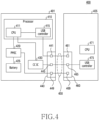
- FIG. 4 is a block diagram 400 illustrating an example of an electronic device 401 and an external electronic device 405 according to various embodiments.
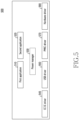
- FIG. 5 is a block diagram 500 illustrating an example program executed in the electronic device 401 according to various embodiments.
- the electronic device 401 in FIG. 4 may correspond to the electronic device 101 in FIG. 1 .
- the external electronic device 405 in FIG. 4 may correspond to the external electronic device 102 in FIG. 1 .
- the program in FIG. 5 may correspond to the program 140 in FIG. 2 .
- the electronic device 401 and the external electronic device 405 may function, while being electrically connected to each other (e.g., while a connector 440 and a connector 460 are electrically connected to each other), as at least one of a master (e.g., a host, a source, or a downstream facing port (DFP) or a slave (e.g., a peripheral device, a sink, or an upstream facing port (UFP)).
- a master e.g., a host, a source, or a downstream facing port (DFP) or a slave (e.g., a peripheral device, a sink, or an upstream facing port (UFP)
- the electronic device 401 and the external electronic device 405 may determine the roles thereof through negotiation in a configuration process.
- a master device may detect attachment or removal of a slave device (e.g., the external electronic device 405) through a connector (e.g., the connector 440).
- the master device e.g., the electronic device 401 may enumerate the slave device (e.g., the external electronic device 405).
- the master device e.g., the electronic device 401 may allocate an address to the slave device (e.g., the external electronic device 405) through the enumeration.
- the master device may manage data flow between the master device (e.g., the electronic device 401) and the slave device (e.g., the external electronic device 405).
- the master device e.g., the electronic device 401 may supply power to the slave device (e.g., the external electronic device 405).
- a device e.g., the electronic device 401 configured to manage data flow may be called a host.
- a device e.g., the external electronic device 405 configured to transmit data under control of a host may be called a peripheral device.
- a device configured to supply power may be a source.
- a device e.g., the external electronic device 405 configured to receive power may be called a sink.
- the electronic device 401 may include a processor (e.g., including processing circuitry) 410, a power management integrated circuit (PMIC) 420, a battery 425, a configuration channel integrated circuit (CC IC) 430, and a connector 440.
- the processor 410 may correspond to the processor 120 in FIG. 1 .
- the PMIC 420 may correspond to the power management module 188 in FIGS. 1 and 3 .
- the battery 425 may correspond to the battery 189 in FIGS. 1 and 3 .
- the connector 440 may correspond to the connection terminal 178 in FIG. 1 .
- the processor 410 may be connected to elements (e.g., the PMIC 420, the CC IC 430, and the connector 440) of the electronic device 401.
- the processor 410 may include various processing circuitry including a CPU 411 and a USB controller 415.
- the CPU 411 of the processor 410 may include various processing circuitry and execute a program for controlling the electronic device 401.
- data for executing a program may be stored in a memory (e.g., the memory 130 in FIG. 1 ) of the electronic device 401.
- the CPU 411 may execute at least one application (a first application 510 or a second application 520).
- the first application 510 may be an application related to the external electronic device 405.
- the second application 520 e.g., an application for providing a payment service
- the CPU 411 may execute at least one application (a first application 510 or a second application 520).
- the first application 510 may be an application related to the external electronic device 405.
- the second application 520 e.g., an application for providing a payment service
- the CPU 411 may drive at least one type of middleware (e.g., a power manager 530).
- the power manager 530 may correspond to the power manager 209 in FIG. 2 .
- the CPU 411 may drive at least one driver (e.g., a CC IC driver 540, a USB driver 550, a PMIC driver 570, a hardware driver 580 (e.g., a display driver or a camera driver), or a combination thereof).
- the CC IC driver 540 may include a program for controlling the CC IC 430.
- the USB driver 550 may include a program for controlling the USB controller 415.
- the PMIC driver 570 may include a program for controlling the PMIC 420.
- the hardware driver 580 may be a program for controlling a hardware element (e.g., a display or a camera) corresponding to the hardware driver 580.
- the CPU 411 may establish, through the CC IC driver 540, a communication channel for communication with the external electronic device 405.
- the CPU 411 may transmit or receive a USB power delivery (PD) message (e.g., a vendor defined message (VDM)) to or from the external electronic device 405 through the CC IC driver 540.
- PD USB power delivery
- the CPU 411 may obtain identification information of the external electronic device 405 using the USB PD message obtained through the CC IC driver 540.
- the identification information may include vendor identity (VID) or product identity (PID).
- VID may be information for identifying a vendor of the external electronic device 405.
- VID may be formed by 2 bytes.
- PID may be information for identifying product information of the external electronic device 405.
- PID may be formed by 2 bytes.
- the CPU 411 may determine a current value of power to be supplied to the external electronic device 405, based on the identification information of the external electronic device 405 identified through the CC IC driver 540.
- the CPU 411 may determine, based on the identification information, whether the external electronic device 405 requires power having a high current value. In an embodiment, when the identification information is included in a list, the CPU 411 may determine that the external electronic device 405 requires power having a high current value. In an embodiment, the list may include identification information regarding devices which require power having a high current value. In an embodiment, the list may be stored in a memory (e.g., the memory 130 in FIG. 1 ) of the electronic device 401.
- the CPU 411 may determine that the external electronic device 405 is a device which requires power having a high current value.
- a designated type of device e.g., a device for providing contents related to augmented reality (AR)
- the CPU 411 may determine that the external electronic device 405 is a device which requires power having a high current value.
- the CPU 411 may transmit or receive data to or from the external electronic device 405 through the USB driver 550. In an embodiment, the CPU 411 may transmit data indicating the result of execution of the first application 510 to the external electronic device 405 through the USB driver 550. In an embodiment, the CPU 411 may receive data, which is to be input into the first application 510, from the external electronic device 405 through the USB driver 550.
- the CPU 411 may determine, based on the execution or non-execution of the first application 510, whether the external electronic device 405 requires power having a high current value. In an embodiment, when the first application 510 is being executed, the CPU 411 may determine that the external electronic device 405 requires power having a high current value.
- the CPU 411 may determine, based on a function provided by the first application 510 through the external electronic device 405, whether the external electronic device 405 requires power having a high current value. In an embodiment, when the first application 510 is performing a designated function, the CPU 411 may determine that the external electronic device 405 requires power having a high current value. In an embodiment, the designated function may be a function for outputting contents (e.g., contents related to AR) to the external electronic device 405.
- the CPU 411 may supply power of the battery 425 to other elements of the electronic device 401 through the PMIC driver 570 of the electronic device 401. In an embodiment, the CPU 411 may supply power of the battery 425 to the external electronic device 405 through the PMIC driver 570.
- the CPU 411 may determine, based on state information of the battery 425, whether the electronic device 401 can supply power having a high current value to the external electronic device 405.
- the CPU 411 may determine that the electronic device 401 can supply power having a high current value to the external electronic device 405. In an embodiment, when the level of the battery 425 is lower than the designated level, the CPU 411 may determine that the electronic device 401 cannot supply power having a high current value to the external electronic device 405.
- a designated level e.g. 30%
- the CPU 411 may determine that the electronic device 401 can supply power having a high current value to the external electronic device 405. In an embodiment, when the battery 425 is being charged in a wireless manner, the CPU 411 may determine that the electronic device 401 can supply power having a high current value to the external electronic device 405.
- the CPU 411 may determine that the electronic device 401 can supply power having a high current value to the external electronic device 405. In an embodiment, when the voltage of the battery 425 is lower than a designated voltage (e.g., 2.6 volts (V)), the CPU 411 may determine that the electronic device 401 can supply power having a high current value to the external electronic device 405.
- a designated voltage e.g. 1.5 volts (V)
- the CPU 411 may determine that the electronic device 401 can supply power having a high current value to the external electronic device 405.
- the CPU 411 may determine that the electronic device 401 can supply power having a high current value to the external electronic device 405. In an embodiment, when the temperature of the electronic device 401 (e.g., the temperature of the battery 425) is lower than a designated temperature, the CPU 411 may determine that the electronic device 401 can supply power having a high current value to the external electronic device 405.
- the CPU 411 may control the PMIC 420 to supply the power having a high current value to the external electronic device 405. In an embodiment, when it is impossible to supply power having a high current value to the external electronic device 405, the CPU 411 may control the PMIC 420 to supply power having a low current value to the external electronic device 405.
- the power having a high current value may, for example, be about 1.5 amperes (A). In an embodiment, the power having a lower current value may, for example, be about 0.9 amperes (A).
- the electronic device 401 may, for example, supply, to the external electronic device 405, 0.5-ampere (A) or 3-ampere (A) power as well as 0.9-ampere (A) or 1.5-ampere (A) power.
- the CPU 411 may control operation of hardware elements of the electronic device 401 (e.g., a display (e.g., the display device 160 in FIG. 1 ) and a camera (e.g., the camera module 180 in FIG. 1 )) through the hardware driver 580.
- a display e.g., the display device 160 in FIG. 1
- a camera e.g., the camera module 180 in FIG. 1
- the CPU 411 may limit functions of the hardware elements (e.g., the display and the camera) while power having a high current value is supplied to the external electronic device 405.
- the CPU 411 may limit the luminance of the display through the hardware driver 580. In an embodiment, the CPU 411 may reduce the luminance of the display to below a designated luminance through the hardware driver 580.
- the CPU 411 may limit driving of a camera through the hardware driver 580. In an embodiment, the CPU 411 may limit execution of camera-related functions through the hardware driver 580. In an embodiment, the CPU 411 may limit, through the hardware driver 580, the resolution of the camera (e.g., the resolution of a preview image or the resolution of a captured image) to below a designated resolution. In an embodiment, the CPU 411 may stop driving of the flash of the camera through the hardware driver 580.
- the resolution of the camera e.g., the resolution of a preview image or the resolution of a captured image
- the CPU 411 may limit functions of hardware elements, which are not used by the first application 510, while power having a high current value is supplied to the external electronic device 405.
- the CPU 411 may stop driving of the second application 520 (e.g., an application for providing a payment service) unrelated to the external electronic device 405 while power having a high current value is supplied to the external electronic device 405.
- the CPU 411 may stop driving of an application, which does not transmit or receive data to or from the external electronic device 405, while power having a high current value is supplied to the external electronic device 405.
- the USB controller 415 may form an electrical path 450 with the external electronic device 405 through the connector 440. In an embodiment, the USB controller 415 may transmit or receive data to or from the external electronic device 405 using the electrical path 450. In an embodiment, the USB controller 415 may transmit or receive data to or from the external electronic device 405 through a data pin 441 of the connector 440 (e.g., a TX pin, an RX pin, a D+ pin, or a D- pin of a USB Type-C connector).
- a data pin 441 of the connector 440 e.g., a TX pin, an RX pin, a D+ pin, or a D- pin of a USB Type-C connector.
- the PMIC 420 may be connected to the processor 410 (e.g., the CPU 411) and the battery 425.
- the PMIC 420 may provide, to the processor 410, state information of the battery 425 (e.g., the amount of electric charge, the charging state, the voltage, or the temperature of the battery 425, or a combination thereof).
- state information of the battery 425 e.g., the amount of electric charge, the charging state, the voltage, or the temperature of the battery 425, or a combination thereof.
- the PMIC 420 may supply power of the battery 425 to other elements of the electronic device 401. In an embodiment, the PMIC 420 may supply, under control of the CPU 411, power of the battery 425 to other elements of the electronic device 401.
- the PMIC 420 may supply power of the battery 425 to the external electronic device 405. In an embodiment, the PMIC 420 may supply, under control of the CPU 411, power of the battery 425 to the external electronic device 405. In an embodiment, the PMIC 420 may supply power to the external electronic device 405 through a power pin 449 of the connector 440 (e.g., a VCONN pin or a VBUS pin of a USB Type-C connector).
- a power pin 449 of the connector 440 e.g., a VCONN pin or a VBUS pin of a USB Type-C connector.
- the PMIC 420 may change a current value of the power which is supplied, under control of the CPU 411, to the external electronic device 405.
- the PMIC 420 may charge the battery 425 using power that is wiredly or wirelessly acquired from the outside. In an embodiment, the PMIC 420 may supply power to other elements of the electronic device 401 while power is acquired from the outside. In an embodiment, the PMIC 420 may wiredly or wirelessly supply power to the external electronic device 405 while power is acquired from the outside.
- the CC IC 430 may be connected to the processor 410 (e.g., the CPU 411) and the connector 440.
- the CC IC 430 may establish a communication channel for communication between the electronic device 401 and the external electronic device 405. In an embodiment, the CC IC 430 may establish a communication channel with the external electronic device 405 through a CC pin 445 of the connector 440 (e.g., a CC1 pin or CC2 pin of a USB Type-C connector).
- a CC pin 445 of the connector 440 e.g., a CC1 pin or CC2 pin of a USB Type-C connector.
- the CC IC 430 may transmit or receive a USB power delivery (PD) message to or from the external electronic device 405. In an embodiment, the CC IC 430 may transmit or receive a vendor defined message (VDM) to or from the external electronic device 405 through the USB PD message.
- PD USB power delivery
- VDM vendor defined message
- the CC IC 430 may provide the received USB PD message to the processor 410. In an embodiment, the CC IC 430 may provide the received VDM to the processor 410.
- the CC IC 430 may obtain identification information of the external electronic device 405 through the USB PD message. In an embodiment, the CC IC 430 may provide the obtained identification information to the processor 410. In an embodiment, the identification information may include vendor identity (VID) and product identity (PID). In an embodiment, VID may be information for identifying a vendor of the external electronic device 405. In an embodiment, VID may, for example, be formed by 2 bytes. In an embodiment, PID may be information for identifying product information of the external electronic device 405. In an embodiment, PID may, for example, be formed by 2 bytes.
- the CC IC 430 in FIG. 4 may be replaced with another element or may be excluded.
- the connector 440 when the connector 440 is implemented as a connector based on any standard other than USB type-C, the CC IC 430 may be replaced with another element or may be excluded.
- the CC IC 430 may be replaced with an identity (ID) identification module.
- the ID identification module may obtain identification information of the external electronic device 405 by identifying a resistance value of the external electronic device 405 through the connector 440.
- the ID identification module may obtain the identification information of the external electronic device 405 by identifying a resistance value of an ID pin of the connector 460 of the external electronic device 405 through an ID pin of connector 440.
- the CC IC 430 may be replaced with an ID identification module.
- the ID identification module may obtain the identification information of the external electronic device 405 from the external electronic device 405 through the connector 440.
- the ID identification module may obtain the identification information of the external electronic device 405 from the external electronic device 405 through an ID pin of the connector 440.
- the external electronic device 405 may include a connector 460, a CPU 471, and a USB controller (e.g., including various circuitry) 475.
- the connector 460 may include multiple pins 461, 465, and 469.
- the pins 461, 465, and 469 may be connected to the pins 441, 445, and 449 of the connector 440 through the electrical path 450, respectively.
- the CPU 471 may process data obtained through the connector 460.
- the USB controller 475 may transmit or receive data to or from the USB controller 415 of the electronic device 401 through the connector 460.
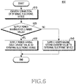
- FIG. 6 is a flowchart 600 illustrating an example operation of the electronic device 401 according to various embodiments.
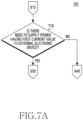
- FIG. 7A is a flowchart 701 illustrating an example operation of the electronic device 401 according to various embodiments.
- FIG. 7B is a flowchart 703 illustrating an example operation of the electronic device 401 according to various embodiments.
- FIG. 7C is a flowchart 705 illustrating an example operation of the electronic device 401 according to various embodiments.
- operation 710 in FIG. 7A , operation 730 in FIG. 7B , and operation 750 in FIG. 7C may be included in operation 620 in FIG. 6 .
- the electronic device 401 may identify connection of the external electronic device 405.
- the electronic device 401 may use the connector 440 to identify connection of the external electronic device 405.
- the electronic device 401 e.g., the processor 410 may identify connection of the external electronic device 405 through a designation pin (e.g., the CC pin 445) of the connector 440.
- the electronic device 401 may use the connector 440 to obtain identification information of the external electronic device 405.
- the electronic device 401 e.g., the processor 410 may obtain the identification information of the external electronic device 405 using a USB PD message (e.g., VDM).
- the identification information may include VID and PID.
- the electronic device 401 may determine whether to supply power having a first current value to the external electronic device 405.
- the electronic device 401 when it is determined, in operation 620, to supply power having the first current value ("Yes” in operation 620), the electronic device 401 (e.g., the processor 410) may perform operation 630. In an embodiment, when it is determined, in operation 620, not to supply power having the first current value ("No" in operation 620), the electronic device 401 (e.g., the processor 410) may perform operation 640.
- the electronic device 401 may determine whether there is a need to supply power having the first current value to the external electronic device 405.
- the electronic device 401 e.g., the processor 410 may determine, based on the identification information of the external electronic device 405 obtained in operation 610, whether there is a need to supply power having the first current value to the external electronic device 405.
- the electronic device 401 may determine, based on the identification information, whether the external electronic device 405 requires power having the first current value. In an embodiment, when the identification information is included in a list, the electronic device 401 (e.g., the processor 410) may determine that the external electronic device 405 requires power having the first current value.
- the electronic device 401 may determine, based on the identification information, whether the identification information indicates a designated type of device (e.g., a device for providing contents related to AR). In an embodiment, when the identification information indicates the designated type of device, the electronic device 401 (e.g., the processor 410) may determine that the external electronic device 405 is requires power having a high current value.
- a designated type of device e.g., a device for providing contents related to AR.
- the electronic device 401 when it is determined, in operation 710, to supply power having the first current value ("Yes” in operation 710), the electronic device 401 (e.g., the processor 410) may perform operation 630. In an embodiment, when it is determined, in operation 710, not to supply power having the first current value ("No" in operation 710), the electronic device 401 (e.g., the processor 410) may perform operation 640.
- the electronic device 401 may determine whether power of the battery 425 is equal to or greater than a designated power.
- the electronic device 401 when it is determined in operation 730 that the power of the battery 425 is equal to or greater than the designated power ("Yes" in operation 730), the electronic device 401 (e.g., the processor 410) may perform operation 630. In an embodiment, when it is determined in operation 730 that the power of the battery 425 is less than the designated power ("No" in operation 730), the electronic device 401 (e.g., the processor 410) may perform operation 640.
- the electronic device 401 may determine whether the first application 510 related to the external electronic device 405 is being executed.
- the electronic device 401 when it is determined in operation 750 that the first application 510 related to the external electronic device 405 is being executed ("Yes" in operation 750), the electronic device 401 (e.g., the processor 410) may perform operation 630. In an embodiment, when it is determined in operation 750 that the first application 510 related to the external electronic device 405 is not being executed ("No" in operation 750), the electronic device 401 (e.g., the processor 410) may perform operation 640.
- the electronic device 401 may determine whether to supply power having the first current value to the external electronic device 405, based on the determination result according to operation 710, the determination result according to operation 730, the determination result according to operation 750, or a combination thereof.
- the electronic device 401 may perform operation 630. In an embodiment, if at least one among the determination result according to operation 710, the determination result according to operation 730, and the determination result according to operation 750 is "No", the electronic device 401 (e.g., the processor 410) may perform operation 640.
- the electronic device 401 may determine, based on a function provided by the first application 510 through the external electronic device 405, whether to supply power having the first current value to the external electronic device 405.
- the electronic device 401 e.g., the processor 410) may perform operation 630.
- the designated function may be a function for outputting contents (e.g., contents related to AR) to the external electronic device 405.
- the electronic device 401 may determine, based on whether the battery 425 is charged, whether to supply power having the first current value to the external electronic device 405. In an embodiment, even when the power of the battery 425 is less than the designated power, the electronic device 401 (e.g., the processor 410) may perform operation 630 if the battery 425 is being charged.
- the electronic device 401 may perform operation 640 when the voltage of the battery 425 is lower than a designated voltage (e.g., 2.6 volts (V)).
- a designated voltage e.g., 2.6 volts (V)
- the electronic device 401 may perform operation 640 when the temperature of the electronic device 401 (e.g., the temperature of the battery 425) exceeds a designated temperature.
- the electronic device 401 may supply power having the first current value to the external electronic device 405.
- the electronic device 401 may supply power having the first current value to the external electronic device 405 through the designated power pin 449 of the connector 440.
- the electronic device 401 may supply power having a second current value to the external electronic device 405.
- the electronic device 401 e.g., the processor 410 may supply power having the second current value to the external electronic device 405 through the designated power pin 449 of the connector 440.
- operation 620 may be repeatedly performed while operation 630 or operation 640 is performed. In an embodiment, operation 620 may be performed again when information regarding a situation of the electronic device 401 (e.g., whether the first application 510 is executed, the amount of power of the battery 425, or whether the battery 425 is charged) is changed.
- information regarding a situation of the electronic device 401 e.g., whether the first application 510 is executed, the amount of power of the battery 425, or whether the battery 425 is charged
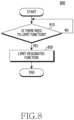
- FIG. 8 is a flowchart 800 illustrating an example operation of the electronic device 401 according to various embodiments. Operations 810 and 820 in FIG. 8 may be performed while operation 630 in FIG. 6 is performed.
- the electronic device 401 may determine whether there is a need to limit a function of the electronic device 401.
- the electronic device 401 when providing power having a first current value to the external electronic device 405, the electronic device 401 (e.g., the processor 410) may determine that there is a need to limit the function of the electronic device 401.
- the electronic device 401 may determine that there is a need to limit of the function of the electronic device 401. In an embodiment, if the battery 425 is being charged while power having the first current value is supplied to the external electronic device 405, the electronic device 401 (e.g., the processor 410) may determine that there is no need to limit of the function of the electronic device 401.
- the electronic device 401 when the temperature of the electronic device 401 (e.g., the temperature of the battery 425) exceeds a designated temperature while supplying power having the first current value to the external electronic device 405, the electronic device 401 (e.g., the processor 410) may determine that there is a need to limit the function of the electronic device 401.
- a temperature reference for determining a current value of power to be supplied to the external electronic device 405 may be different from a temperature reference for determining whether to limit the function of the electronic device 401.
- the temperature reference for determining whether to limit the function of the electronic device 401 may be lower than the temperature reference for determining a current value of power to be supplied to the external electronic device 405.
- the electronic device 401 when it is determined in operation 810 that there is a need to limit the function of the electronic device 401 ("Yes" determination), the electronic device 401 (e.g., the processor 410) may perform operation 820. In an embodiment, when it is determined in operation 810 that there is no need to limit the function of the electronic device 401 ("No" determination), the electronic device 401 (e.g., the processor 410) may perform operation 810 again.
- the electronic device 401 may limit a designated function of the electronic device 401.
- the electronic device 401 may stop driving of the second application 520 (e.g., an application for providing a payment service) which is unrelated to the external electronic device 405.
- the electronic device 401 e.g., the processor 410) may stop driving of an application that does not transmit or receive data to or from the external electronic device 405.
- the electronic device 401 may limit the function of a hardware element which is not used by the first application 510.
- the electronic device 401 e.g., the processor 410) may limit the luminance of a display (e.g., the display device 160 in FIG. 1 ).
- the electronic device 401 e.g., the processor 410) may limit driving of a camera (e.g., the camera module180 in FIG. 1 ).
- An electronic device may include: a battery; a connector including multiple pins; and a processor, wherein the processor is configured to: identify an external electronic device electrically connected through the connector; identify, among at least two supportable current values, a current value of power to be supplied to the external electronic device; and supply, based on the identified current value, power of the battery to the external electronic device through the connector, wherein the electronic device may be configured to perform, among the roles of a host and a peripheral device, the role of the host while being connected to the external electronic device through the connector.
- the processor may be configured to identify the current value, based on identification information of the external electronic device.
- the processor may be configured to: identify, based on the identification information, the type of the external electronic device; and identify the current value, based on the type of the external electronic device.
- the processor may be configured to identify the current value, based on whether an application related to the external electronic device is executed.
- the processor may be configured to identify the current value, based on a function provided by the application, when the application being executed.
- the processor may be configured to identify the current value, based on the amount of electric charge of the battery.
- the processor may be configured to identify the current value, based on whether the battery is charged.
- the processor may be configured to identify the current value, based on the temperature of the electronic device.
- the processor may be configured to limit, based on the identified current value being greater than a designated current value, a designated function of the electronic device while the power of the battery is supplied to the external electronic device based on the identified current value.
- the processor may be configured to limit the designated function by limiting a payment service, a luminance of a display (e.g., the luminance of the display device 160), a camera (e.g., the camera module 180), or a combination thereof while the power of the battery is supplied to the external electronic device based on the identified current value.
- a luminance of a display e.g., the luminance of the display device 160
- a camera e.g., the camera module 180
- the processor may be configured to limit the designated function by limiting a payment service, a luminance of a display (e.g., the luminance of the display device 160), a camera (e.g., the camera module 180), or a combination thereof while the power of the battery is supplied to the external electronic device based on the identified current value.
- a method of operating an electronic device may include: identifying an external electronic device electrically connected through a connector of the electronic device; identifying, among at least two supportable current values, a current value of power to be supplied to the external electronic device; and supplying, based on the identified current value, power of a battery of the electronic device to the external electronic device through the connector, wherein the electronic device is configured to perform, among the roles of a host and a peripheral device, the role of the host while being connected to the external electronic device through the connector.
- the identifying of the current value may include identifying the current value, based on identification information of the external electronic device.
- the identifying of the current value may include: identifying, based on the identification information, the type of the external electronic device; and identifying the current value, based on the type of the external electronic device.
- the identifying of the current value may include identifying the current value, based on whether an application related to the external electronic device is executed.
- the identifying of the current value may include identifying the current value, based on a function provided by the application, based on the application being executed.
- the identifying of the current value may include identifying the current value, based on the amount of electric charge of the battery.
- the identifying of the current value may include identifying the current value, based on whether the battery is charged.
- the identifying of the current value may include identifying the current value, based on the temperature of the electronic device.
- the method may further include: limiting, based on the identified current value being greater than a designated current value, a designated function of the electronic device while power of the battery is supplied to the external electronic device based on the identified current value.
- the limiting of the designated function of the electronic device may include: limiting the designated function by limiting a payment service, the luminance of a display (e.g., the luminance of the display device 160), a camera (e.g., the camera module 180), or a combination thereof while power of the battery is supplied to the external electronic device based on the identified current value.
- the electronic device may be one of various types of electronic devices.
- the electronic devices may include, for example, a portable communication device (e.g., a smartphone), a computer device, a portable multimedia device, a portable medical device, a camera, a wearable device, or a home appliance. According to an embodiment of the disclosure, the electronic devices are not limited to those described above.
- each of such phrases as “A or B,” “at least one of A and B,” “at least one of A or B,” “A, B, or C,” “at least one of A, B, and C,” and “at least one of A, B, or C,” may include any one of, or all possible combinations of the items enumerated together in a corresponding one of the phrases.
- such terms as “1st” and “2nd,” or “first” and “second” may be used to simply distinguish a corresponding component from another, and does not limit the components in other aspect (e.g., importance or order).
- an element e.g., a first element
- the element may be coupled with the other element directly (e.g., wiredly), wirelessly, or via a third element.
- module may include a unit implemented in hardware, software, or firmware, or any combination thereof, and may interchangeably be used with other terms, for example, “logic,” “logic block,” “part,” or “circuitry”.
- a module may be a single integral component, or a minimum unit or part thereof, adapted to perform one or more functions.
- the module may be implemented in a form of an application-specific integrated circuit (ASIC).
- ASIC application-specific integrated circuit
- Various embodiments as set forth herein may be implemented as software (e.g., the program 140) including one or more instructions that are stored in a storage medium (e.g., internal memory 136 or external memory 138) that is readable by a machine (e.g., the electronic device 101) .
- a processor(e.g., the processor 120) of the machine e.g., the electronic device 101
- the one or more instructions may include a code generated by a complier or a code executable by an interpreter.
- the machine-readable storage medium may be provided in the form of a non-transitory storage medium.
- non-transitory simply means that the storage medium is a tangible device, and may not include a signal (e.g., an electromagnetic wave), but this term does not differentiate between where data is semi-permanently stored in the storage medium and where the data is temporarily stored in the storage medium.
- a method may be included and provided in a computer program product.
- the computer program product may be traded as a product between a seller and a buyer.
- the computer program product may be distributed in the form of a machine-readable storage medium (e.g., compact disc read only memory (CD-ROM)), or be distributed (e.g., downloaded or uploaded) online via an application store (e.g., PlayStore TM ), or between two user devices (e.g., smart phones) directly. If distributed online, at least part of the computer program product may be temporarily generated or at least temporarily stored in the machine-readable storage medium, such as memory of the manufacturer's server, a server of the application store, or a relay server.
- CD-ROM compact disc read only memory
- an application store e.g., PlayStore TM
- two user devices e.g., smart phones
- each component e.g., a module or a program of the above-described components may include a single entity or multiple entities. According to various embodiments, one or more of the above-described components may be omitted, or one or more other components may be added. Alternatively or additionally, a plurality of components (e.g., modules or programs) may be integrated into a single component. In such a case, according to various embodiments, the integrated component may still perform one or more functions of each of the plurality of components in the same or similar manner as they are performed by a corresponding one of the plurality of components before the integration.
- operations performed by the module, the program, or another component may be carried out sequentially, in parallel, repeatedly, or heuristically, or one or more of the operations may be executed in a different order or omitted, or one or more other operations may be added.
Landscapes
- Engineering & Computer Science (AREA)
- Theoretical Computer Science (AREA)
- General Engineering & Computer Science (AREA)
- Physics & Mathematics (AREA)
- General Physics & Mathematics (AREA)
- Computer Hardware Design (AREA)
- Power Engineering (AREA)
- Human Computer Interaction (AREA)
- Computer Networks & Wireless Communication (AREA)
- Signal Processing (AREA)
- Power Sources (AREA)
- Charge And Discharge Circuits For Batteries Or The Like (AREA)
Abstract
Description
- The disclosure relates to an electronic device for supplying power and an operation method thereof.
- An electronic device may provide power to an external electronic device using wired and wireless interfaces. Such an electronic device may include a power management integrated circuit (PMIC) for managing power supplied to the external electronic device.
- An electronic device may provide power to an external electronic device, based on a protocol related to a wired interface. In this case, the external electronic device may fail to receive the necessary amount of power. Accordingly, the external electronic device may fail to operate.
- Technical problems addressed in the disclosure are not limited to the above-mentioned technical problems, and other technical problems not mentioned herein will be clearly understood from the following description by those skilled in the art to which the disclosure pertains.
- An electronic device according to an example embodiment may include: a battery; a connector including multiple pins; and at least one processor, wherein the at least one processor is configured to: identify an external electronic device electrically connected through the connector; identify, among at least two supportable current values, a current value of power to be supplied to the external electronic device; and supply, based on the identified current value, power of the battery to the external electronic device through the connector.
- A method of operating an electronic device according to an example embodiment may include: identifying an external electronic device electrically connected through a connector of the electronic device; identifying, among at least two supportable current values, a current value of power to be supplied to the external electronic device; and supplying, based on the identified current value, power of a battery of the electronic device to the external electronic device through the connector.
- An electronic device and an operation method thereof, according to various example embodiments, may provide necessary power to an external electronic device.
- Advantageous effects obtainable from the disclosure are not limited to the above-mentioned advantageous effects, and other advantageous effects not mentioned herein will be clearly understood from the following description by those skilled in the art to which the disclosure pertains.
-
-
FIG. 1 is a block diagram illustrating an example electronic device in a network environment according to various embodiments. -
FIG. 2 is a block diagram illustrating an example program according to various embodiments. -
FIG. 3 is a block diagram illustrating an example of a power management module and a battery according to various embodiments. -
FIG. 4 is a block diagram illustrating an example electronic device and an external electronic device according to various embodiments. -
FIG. 5 is a block diagram illustrating an example program executed in an electronic device according to various embodiments. -
FIG. 6 is a flowchart illustrating an example operation of an electronic device according to various embodiments. -
FIG. 7A is a flowchart illustrating an example operation of an electronic device according to various embodiments. -
FIG. 7B is a flowchart illustrating an example operation of an electronic device according to various embodiments. -
FIG. 7C is a flowchart illustrating an example operation of an electronic device according to various embodiments. -
FIG. 8 is a flowchart illustrating an example operation of an electronic device according to various embodiments. -
Fig. 1 is a block diagram illustrating an exampleelectronic device 101 in anetwork environment 100 according to various embodiments. Referring toFig. 1 , theelectronic device 101 in thenetwork environment 100 may communicate with anelectronic device 102 via a first network 198 (e.g., a short-range wireless communication network), or anelectronic device 104 or aserver 108 via a second network 199 (e.g., a long-range wireless communication network). According to an embodiment, theelectronic device 101 may communicate with theelectronic device 104 via theserver 108. According to an embodiment, theelectronic device 101 may include aprocessor 120,memory 130, aninput device 150, asound output device 155, adisplay device 160, anaudio module 170, asensor module 176, aninterface 177, ahaptic module 179, acamera module 180, apower management module 188, abattery 189, acommunication module 190, a subscriber identification module (SIM) 196, or anantenna module 197. In some embodiments, at least one (e.g., thedisplay device 160 or the camera module 180) of the components may be omitted from theelectronic device 101, or one or more other components may be added in theelectronic device 101. In some embodiments, some of the components may be implemented as single integrated circuitry. For example, the sensor module 176 (e.g., a fingerprint sensor, an iris sensor, or an illuminance sensor) may be implemented as embedded in the display device 160 (e.g., a display). - The
processor 120 may execute, for example, software (e.g., a program 140) to control at least one other component (e.g., a hardware or software component) of theelectronic device 101 coupled with theprocessor 120, and may perform various data processing or computation. According to an embodiment, as at least part of the data processing or computation, theprocessor 120 may load a command or data received from another component (e.g., thesensor module 176 or the communication module 190) involatile memory 132, process the command or the data stored in thevolatile memory 132, and store resulting data innon-volatile memory 134. According to an embodiment, theprocessor 120 may include a main processor 121 (e.g., a central processing unit (CPU) or an application processor (AP)), and an auxiliary processor 123 (e.g., a graphics processing unit (GPU), an image signal processor (ISP), a sensor hub processor, or a communication processor (CP)) that is operable independently from, or in conjunction with, themain processor 121. Additionally or alternatively, theauxiliary processor 123 may be adapted to consume less power than themain processor 121, or to be specific to a specified function. Theauxiliary processor 123 may be implemented as separate from, or as part of themain processor 121. - The
auxiliary processor 123 may control at least some of functions or states related to at least one component (e.g., thedisplay device 160, thesensor module 176, or the communication module 190) among the components of theelectronic device 101, instead of themain processor 121 while themain processor 121 is in an inactive (e.g., sleep) state, or together with themain processor 121 while themain processor 121 is in an active state (e.g., executing an application). According to an embodiment, the auxiliary processor 123 (e.g., an image signal processor or a communication processor) may be implemented as part of another component (e.g., thecamera module 180 or the communication module 190) functionally related to theauxiliary processor 123. - The
memory 130 may store various data used by at least one component (e.g., theprocessor 120 or the sensor module 176) of theelectronic device 101. The various data may include, for example, software (e.g., the program 140) and input data or output data for a command related thereto. Thememory 130 may include thevolatile memory 132 or thenon-volatile memory 134. - The
program 140 may be stored in thememory 130 as software, and may include, for example, an operating system (OS) 142,middleware 144, or anapplication 146. - The
input device 150 may receive a command or data to be used by other component (e.g., the processor 120) of theelectronic device 101, from the outside (e.g., a user) of theelectronic device 101. Theinput device 150 may include, for example, a microphone, a mouse, a keyboard, or a digital pen (e.g., a stylus pen). - The
sound output device 155 may output sound signals to the outside of theelectronic device 101. Thesound output device 155 may include, for example, a speaker or a receiver. The speaker may be used for general purposes, such as playing multimedia or playing record, and the receiver may be used for an incoming calls. According to an embodiment, the receiver may be implemented as separate from, or as part of the speaker. - The
display device 160 may visually provide information to the outside (e.g., a user) of theelectronic device 101. Thedisplay device 160 may include, for example, a display, a hologram device, or a projector and control circuitry to control a corresponding one of the display, hologram device, and projector. According to an embodiment, thedisplay device 160 may include touch circuitry adapted to detect a touch, or sensor circuitry (e.g., a pressure sensor) adapted to measure the intensity of force incurred by the touch. - The
audio module 170 may convert a sound into an electrical signal and vice versa. According to an embodiment, theaudio module 170 may obtain the sound via theinput device 150, or output the sound via thesound output device 155 or a headphone of an external electronic device (e.g., an electronic device 102) directly (e.g., wiredly) or wirelessly coupled with theelectronic device 101. - The
sensor module 176 may detect an operational state (e.g., power or temperature) of theelectronic device 101 or an environmental state (e.g., a state of a user) external to theelectronic device 101, and then generate an electrical signal or data value corresponding to the detected state. According to an embodiment, thesensor module 176 may include, for example, a gesture sensor, a gyro sensor, an atmospheric pressure sensor, a magnetic sensor, an acceleration sensor, a grip sensor, a proximity sensor, a color sensor, an infrared (IR) sensor, a biometric sensor, a temperature sensor, a humidity sensor, or an illuminance sensor. - The
interface 177 may support one or more specified protocols to be used for theelectronic device 101 to be coupled with the external electronic device (e.g., the electronic device 102) directly (e.g., wiredly) or wirelessly. According to an embodiment, theinterface 177 may include, for example, a high definition multimedia interface (HDMI), a universal serial bus (USB) interface, a secure digital (SD) card interface, or an audio interface. - A connecting
terminal 178 may include a connector via which theelectronic device 101 may be physically connected with the external electronic device (e.g., the electronic device 102). According to an embodiment, the connectingterminal 178 may include, for example, a HDMI connector, a USB connector, a SD card connector, or an audio connector (e.g., a headphone connector). - The
haptic module 179 may convert an electrical signal into a mechanical stimulus (e.g., a vibration or a movement) or electrical stimulus which may be recognized by a user via his tactile sensation or kinesthetic sensation. According to an embodiment, thehaptic module 179 may include, for example, a motor, a piezoelectric element, or an electric stimulator. - The
camera module 180 may capture a still image or moving images. According to an embodiment, thecamera module 180 may include one or more lenses, image sensors, image signal processors, or flashes. - The
power management module 188 may manage power supplied to theelectronic device 101. According to an embodiment, thepower management module 188 may be implemented as at least part of, for example, a power management integrated circuit (PMIC). - The
battery 189 may supply power to at least one component of theelectronic device 101. According to an embodiment, thebattery 189 may include, for example, a primary cell which is not rechargeable, a secondary cell which is rechargeable, or a fuel cell. - The
communication module 190 may support establishing a direct (e.g., wired) communication channel or a wireless communication channel between theelectronic device 101 and the external electronic device (e.g., theelectronic device 102, theelectronic device 104, or the server 108) and performing communication via the established communication channel. Thecommunication module 190 may include one or more communication processors that are operable independently from the processor 120 (e.g., the application processor (AP)) and supports a direct (e.g., wired) communication or a wireless communication. According to an embodiment, thecommunication module 190 may include a wireless communication module 192 (e.g., a cellular communication module, a short-range wireless communication module, or a global navigation satellite system (GNSS) communication module) or a wired communication module 194 (e.g., a local area network (LAN) communication module or a power line communication (PLC) module). A corresponding one of these communication modules may communicate with the external electronic device via the first network 198 (e.g., a short-range communication network, such as Bluetooth™, wireless-fidelity (Wi-Fi) direct, or infrared data association (IrDA)) or the second network 199 (e.g., a long-range communication network, such as a cellular network, the Internet, or a computer network (e.g., LAN or wide area network (WAN)). These various types of communication modules may be implemented as a single component (e.g., a single chip), or may be implemented as multi components (e.g., multi chips) separate from each other. The wireless communication module 192 may identify and authenticate theelectronic device 101 in a communication network, such as thefirst network 198 or thesecond network 199, using subscriber information (e.g., international mobile subscriber identity (IMSI)) stored in thesubscriber identification module 196. - The
antenna module 197 may transmit or receive a signal or power to or from the outside (e.g., the external electronic device) of theelectronic device 101. According to an embodiment, theantenna module 197 may include an antenna including a radiating element composed of a conductive material or a conductive pattern formed in or on a substrate (e.g., PCB). According to an embodiment, theantenna module 197 may include a plurality of antennas. In such a case, at least one antenna appropriate for a communication scheme used in the communication network, such as thefirst network 198 or thesecond network 199, may be selected, for example, by the communication module 190 (e.g., the wireless communication module 192) from the plurality of antennas. The signal or the power may then be transmitted or received between thecommunication module 190 and the external electronic device via the selected at least one antenna. According to an embodiment, another component (e.g., a radio frequency integrated circuit (RFIC)) other than the radiating element may be additionally formed as part of theantenna module 197. - At least some of the above-described components may be coupled mutually and communicate signals (e.g., commands or data) therebetween via an inter-peripheral communication scheme (e.g., a bus, general purpose input and output (GPIO), serial peripheral interface (SPI), or mobile industry processor interface (MIPI)).
- According to an embodiment, commands or data may be transmitted or received between the
electronic device 101 and the externalelectronic device 104 via theserver 108 coupled with thesecond network 199. Each of theelectronic devices electronic device 101. According to an embodiment, all or some of operations to be executed at theelectronic device 101 may be executed at one or more of the externalelectronic devices electronic device 101 should perform a function or a service automatically, or in response to a request from a user or another device, theelectronic device 101, instead of, or in addition to, executing the function or the service, may request the one or more external electronic devices to perform at least part of the function or the service. The one or more external electronic devices receiving the request may perform the at least part of the function or the service requested, or an additional function or an additional service related to the request, and transfer an outcome of the performing to theelectronic device 101. Theelectronic device 101 may provide the outcome, with or without further processing of the outcome, as at least part of a reply to the request. To that end, a cloud computing, distributed computing, or client-server computing technology may be used, for example. -
Fig. 2 is a block diagram 200 illustrating an example of theprogram 140 according to various embodiments. According to an embodiment, theprogram 140 may include an operating system (OS) 142 to control one or more resources of theelectronic device 101,middleware 144, or anapplication 146 executable in theOS 142. TheOS 142 may include, for example, Android™, iOS™, Windows™, Symbian™, Tizen™, or Bada™. At least part of theprogram 140, for example, may be pre-loaded on theelectronic device 101 during manufacture, or may be downloaded from or updated by an external electronic device (e.g., theelectronic device - The
OS 142 may control management (e.g., allocating or deallocation) of one or more system resources (e.g., process, memory, or power source) of theelectronic device 101. TheOS 142 may include one or more driver programs to drive other hardware devices of theelectronic device 101, for example, theinput device 150, thesound output device 155, thedisplay device 160, theaudio module 170, thesensor module 176, theinterface 177, thehaptic module 179, thecamera module 180, thepower management module 188, thebattery 189, thecommunication module 190, thesubscriber identification module 196, or theantenna module 197. - The
middleware 144 may provide various functions to theapplication 146 such that a function or information provided from one or more resources of theelectronic device 101 may be used by theapplication 146. Themiddleware 144 may include, for example, anapplication manager 201, awindow manager 203, amultimedia manager 205, aresource manager 207, apower manager 209, adatabase manager 211, apackage manager 213, aconnectivity manager 215, anotification manager 217, alocation manager 219, agraphic manager 221, asecurity manager 223, atelephony manager 225, and/or avoice recognition manager 227. - The
application manager 201, for example, may manage the life cycle of theapplication 146. Thewindow manager 203, for example, may manage one or more graphical user interface (GUI) resources that are used on a screen. Themultimedia manager 205, for example, may identify one or more formats to be used to play media files, and may encode or decode a corresponding one of the media files using a codec appropriate for a corresponding format selected from the one or more formats. Theresource manager 207, for example, may manage the source code of theapplication 146 or a memory space of the memory 130.Thepower manager 209, for example, may manage the capacity, temperature, or power of thebattery 189, and determine or provide related information to be used for the operation of theelectronic device 101 based at least in part on corresponding information of the capacity, temperature, or power of thebattery 189. According to an embodiment, thepower manager 209 may interwork with a basic input/output system (BIOS) (not shown) of theelectronic device 101. - The
database manager 211, for example, may generate, search, or change a database to be used by theapplication 146. Thepackage manager 213, for example, may manage installation or update of an application that is distributed in the form of a package file. Theconnectivity manager 215, for example, may manage a wireless connection or a direct connection between theelectronic device 101 and the external electronic device. Thenotification manager 217, for example, may provide a function to notify a user of an occurrence of a specified event (e.g., an incoming call, message, or alert). Thelocation manager 219, for example, may manage locational information on theelectronic device 101. Thegraphic manager 221, for example, may manage one or more graphic effects to be offered to a user or a user interface related to the one or more graphic effects. - The
security manager 223, for example, may provide system security or user authentication. Thetelephony manager 225, for example, may manage a voice call function or a video call function provided by theelectronic device 101. Thevoice recognition manager 227, for example, may transmit a user's voice data to theserver 108, and receive, from theserver 108, a command corresponding to a function to be executed on theelectronic device 101 based at least in part on the voice data, or text data converted based at least in part on the voice data. According to an embodiment, the middleware 244 may dynamically delete some existing components or add new components. According to an embodiment, at least part of themiddleware 144 may be included as part of theOS 142 or may be implemented as another software separate from theOS 142. - The
application 146 may include, for example, ahome 251,dialer 253, short message service (SMS)/multimedia messaging service (MMS) 255, instant message (IM) 257,browser 259,camera 261,alarm 263, contact 265,voice recognition 267,email 269,calendar 271,media player 273,album 275, watch 277, health 279 (e.g., for measuring the degree of workout or biometric information, such as blood sugar), and/or environmental information 281 (e.g., for measuring air pressure, humidity, or temperature information) application. According to an embodiment, theapplication 146 may further include an information exchanging application (not shown) that is capable of supporting information exchange between theelectronic device 101 and the external electronic device. The information exchange application, for example, may include a notification relay application adapted to transfer designated information (e.g., a call, message, or alert) to the external electronic device or a device management application adapted to manage the external electronic device. The notification relay application may transfer notification information corresponding to an occurrence of a specified event (e.g., receipt of an email) at another application (e.g., the email application 269) of theelectronic device 101 to the external electronic device. Additionally or alternatively, the notification relay application may receive notification information from the external electronic device and provide the notification information to a user of theelectronic device 101. - The device management application may control the power (e.g., turn-on or turn-off) or the function (e.g., adjustment of brightness, resolution, or focus) of the external electronic device or some component thereof (e.g., a display device or a camera module of the external electronic device). The device management application, additionally or alternatively, may support installation, delete, or update of an application running on the external electronic device.
-
Fig. 3 is a block diagram 300 illustrating an example of apower management module 188 and thebattery 189 according to various embodiments. Referring toFig. 3 , thepower management module 188 may include chargingcircuit including circuitry 310, a power adjusting unit (e.g., including power adjusting circuitry) 320, and/or apower gauge 330. The chargingcircuitry 310 may charge thebattery 189 using power supplied from an external power source outside theelectronic device 101. According to an embodiment, the chargingcircuitry 310 may select a charging scheme (e.g., normal charging or quick charging) based at least in part on, for example, and without limitation, a type of the external power source (e.g., a power outlet, a USB, or wireless charging), magnitude of power suppliable from the external power source (e.g., about 20 Watt or more), an attribute of thebattery 189, etc., and may charge thebattery 189 using the selected charging scheme. The external power source may be connected with theelectronic device 101, for example, directly via the connectingterminal 178 or wirelessly via theantenna module 197. - The power adjusting unit 320 may include power adjusting circuitry and generate a plurality of powers having different voltage levels or different current levels by adjusting a voltage level or a current level of the power supplied from the external power source or the
battery 189. The power adjusting unit 320 may adjust the voltage level or the current level of the power supplied from the external power source or thebattery 189 into a different voltage level or current level appropriate for each of some of the components included in theelectronic device 101. According to an embodiment, the power adjusting unit 320 may be implemented in the form of a low drop out (LDO) regulator or a switching regulator. Thepower gauge 330 may measure use state information about the battery 189 (e.g., a capacity, a number of times of charging or discharging, a voltage, or a temperature of the battery 189). - The
power management module 188 may determine, using, for example, the chargingcircuitry 310, the power adjusting unit 320, or thepower gauge 330, charging state information (e.g., lifetime, over voltage, low voltage, over current, over charge, over discharge, overheat, short, or swelling) related to the charging of thebattery 189 based at least in part on the measured use state information about thebattery 189. Thepower management module 188 may determine whether the state of thebattery 189 is normal or abnormal based at least in part on the determined charging state information. If the state of thebattery 189 is determined to abnormal, thepower management module 188 may adjust the charging of the battery 189 (e.g., reduce the charging current or voltage, or stop the charging). According to an embodiment, at least some of the functions of thepower management module 188 may be performed by an external control device (e.g., the processor 120). - The
battery 189, according to an embodiment, may include a battery protection circuit module (PCM) 340. ThePCM 340 may perform one or more of various functions (e.g., a pre-cutoff function) to prevent a performance deterioration of, or a damage to, thebattery 189. ThePCM 340, additionally or alternatively, may be configured as at least part of a battery management system (BMS) capable of performing various functions including cell balancing, measurement of battery capacity, count of a number of charging or discharging, measurement of temperature, or measurement of voltage. - According to an embodiment, at least part of the charging state information or use state information regarding the
battery 189 may be measured using a corresponding sensor (e.g., a temperature sensor) of thesensor module 176, thepower gauge 330, or thepower management module 188.. According to an embodiment, the corresponding sensor (e.g., a temperature sensor) of thesensor module 176 may be included as part of thePCM 340, or may be disposed near thebattery 189 as a separate device. -
FIG. 4 is a block diagram 400 illustrating an example of an electronic device 401 and an externalelectronic device 405 according to various embodiments.FIG. 5 is a block diagram 500 illustrating an example program executed in the electronic device 401 according to various embodiments. In an embodiment, the electronic device 401 inFIG. 4 may correspond to theelectronic device 101 inFIG. 1 . In an embodiment, the externalelectronic device 405 inFIG. 4 may correspond to the externalelectronic device 102 inFIG. 1 . In an embodiment, the program inFIG. 5 may correspond to theprogram 140 inFIG. 2 . - In an embodiment, the electronic device 401 and the external
electronic device 405 may function, while being electrically connected to each other (e.g., while aconnector 440 and aconnector 460 are electrically connected to each other), as at least one of a master (e.g., a host, a source, or a downstream facing port (DFP) or a slave (e.g., a peripheral device, a sink, or an upstream facing port (UFP)). In an embodiment, while the electronic device 401 and the externalelectronic device 405 are electrically connected to each other through theconnector 440 and theconnector 460, the electronic device 401 and the externalelectronic device 405 may determine the roles thereof through negotiation in a configuration process. - In an embodiment, a master device (e.g., the electronic device 401) may detect attachment or removal of a slave device (e.g., the external electronic device 405) through a connector (e.g., the connector 440). In an embodiment, the master device (e.g., the electronic device 401) may enumerate the slave device (e.g., the external electronic device 405). In an embodiment, the master device (e.g., the electronic device 401) may allocate an address to the slave device (e.g., the external electronic device 405) through the enumeration. In an embodiment, the master device (e.g., the electronic device 401) may manage data flow between the master device (e.g., the electronic device 401) and the slave device (e.g., the external electronic device 405). In an embodiment, the master device (e.g., the electronic device 401) may supply power to the slave device (e.g., the external electronic device 405).
- In an embodiment, in terms of data transmission, a device (e.g., the electronic device 401) configured to manage data flow may be called a host. In an embodiment, in terms of data transmission, a device (e.g., the external electronic device 405) configured to transmit data under control of a host may be called a peripheral device.
- In an embodiment, in terms of power transmission, a device (e.g., the electronic device 401) configured to supply power may be a source. In an embodiment, in terms of power transmission, a device (e.g., the external electronic device 405) configured to receive power may be called a sink.
- In an embodiment, the electronic device 401 may include a processor (e.g., including processing circuitry) 410, a power management integrated circuit (PMIC) 420, a
battery 425, a configuration channel integrated circuit (CC IC) 430, and aconnector 440. In an embodiment, theprocessor 410 may correspond to theprocessor 120 inFIG. 1 . In an embodiment, thePMIC 420 may correspond to thepower management module 188 inFIGS. 1 and3 . In an embodiment, thebattery 425 may correspond to thebattery 189 inFIGS. 1 and3 . In an embodiment, theconnector 440 may correspond to theconnection terminal 178 inFIG. 1 . - In an embodiment, the
processor 410 may be connected to elements (e.g., thePMIC 420, theCC IC 430, and the connector 440) of the electronic device 401. In an embodiment, theprocessor 410 may include various processing circuitry including aCPU 411 and aUSB controller 415. - In an embodiment, the
CPU 411 of theprocessor 410 may include various processing circuitry and execute a program for controlling the electronic device 401. In an embodiment, data for executing a program may be stored in a memory (e.g., thememory 130 inFIG. 1 ) of the electronic device 401. - In an embodiment, the
CPU 411 may execute at least one application (afirst application 510 or a second application 520). In an embodiment, thefirst application 510 may be an application related to the externalelectronic device 405. In an embodiment, the second application 520 (e.g., an application for providing a payment service) may be an application which is not related to the externalelectronic device 405. - In an embodiment, the
CPU 411 may drive at least one type of middleware (e.g., a power manager 530). In an embodiment, thepower manager 530 may correspond to thepower manager 209 inFIG. 2 . - In an embodiment, the
CPU 411 may drive at least one driver (e.g., aCC IC driver 540, aUSB driver 550, aPMIC driver 570, a hardware driver 580 (e.g., a display driver or a camera driver), or a combination thereof). In an embodiment, theCC IC driver 540 may include a program for controlling theCC IC 430. In an embodiment, theUSB driver 550 may include a program for controlling theUSB controller 415. In an embodiment, thePMIC driver 570 may include a program for controlling thePMIC 420. In an embodiment, thehardware driver 580 may be a program for controlling a hardware element (e.g., a display or a camera) corresponding to thehardware driver 580. - In an embodiment, the
CPU 411 may establish, through theCC IC driver 540, a communication channel for communication with the externalelectronic device 405. In an embodiment, theCPU 411 may transmit or receive a USB power delivery (PD) message (e.g., a vendor defined message (VDM)) to or from the externalelectronic device 405 through theCC IC driver 540. In an embodiment, theCPU 411 may obtain identification information of the externalelectronic device 405 using the USB PD message obtained through theCC IC driver 540. In an embodiment, the identification information may include vendor identity (VID) or product identity (PID). In an embodiment, VID may be information for identifying a vendor of the externalelectronic device 405. In an embodiment, VID may be formed by 2 bytes. In an embodiment, PID may be information for identifying product information of the externalelectronic device 405. In an embodiment, PID may be formed by 2 bytes. - In an embodiment, the
CPU 411 may determine a current value of power to be supplied to the externalelectronic device 405, based on the identification information of the externalelectronic device 405 identified through theCC IC driver 540. - In an embodiment, the
CPU 411 may determine, based on the identification information, whether the externalelectronic device 405 requires power having a high current value. In an embodiment, when the identification information is included in a list, theCPU 411 may determine that the externalelectronic device 405 requires power having a high current value. In an embodiment, the list may include identification information regarding devices which require power having a high current value. In an embodiment, the list may be stored in a memory (e.g., thememory 130 inFIG. 1 ) of the electronic device 401. - In an embodiment, when the identification information indicates a designated type of device (e.g., a device for providing contents related to augmented reality (AR)), the
CPU 411 may determine that the externalelectronic device 405 is a device which requires power having a high current value. - In an embodiment, the
CPU 411 may transmit or receive data to or from the externalelectronic device 405 through theUSB driver 550. In an embodiment, theCPU 411 may transmit data indicating the result of execution of thefirst application 510 to the externalelectronic device 405 through theUSB driver 550. In an embodiment, theCPU 411 may receive data, which is to be input into thefirst application 510, from the externalelectronic device 405 through theUSB driver 550. - In an embodiment, the
CPU 411 may determine, based on the execution or non-execution of thefirst application 510, whether the externalelectronic device 405 requires power having a high current value. In an embodiment, when thefirst application 510 is being executed, theCPU 411 may determine that the externalelectronic device 405 requires power having a high current value. - In an embodiment, when the
first application 510 is being executed, theCPU 411 may determine, based on a function provided by thefirst application 510 through the externalelectronic device 405, whether the externalelectronic device 405 requires power having a high current value. In an embodiment, when thefirst application 510 is performing a designated function, theCPU 411 may determine that the externalelectronic device 405 requires power having a high current value. In an embodiment, the designated function may be a function for outputting contents (e.g., contents related to AR) to the externalelectronic device 405. - In an embodiment, the
CPU 411 may supply power of thebattery 425 to other elements of the electronic device 401 through thePMIC driver 570 of the electronic device 401. In an embodiment, theCPU 411 may supply power of thebattery 425 to the externalelectronic device 405 through thePMIC driver 570. - In an embodiment, the
CPU 411 may determine, based on state information of thebattery 425, whether the electronic device 401 can supply power having a high current value to the externalelectronic device 405. - In an embodiment, when the level (e.g., state of charging (SOC)) of the
battery 425 is equal to or higher than a designated level (e.g., 30%), theCPU 411 may determine that the electronic device 401 can supply power having a high current value to the externalelectronic device 405. In an embodiment, when the level of thebattery 425 is lower than the designated level, theCPU 411 may determine that the electronic device 401 cannot supply power having a high current value to the externalelectronic device 405. - In an embodiment, when the
battery 425 is being charged, theCPU 411 may determine that the electronic device 401 can supply power having a high current value to the externalelectronic device 405. In an embodiment, when thebattery 425 is being charged in a wireless manner, theCPU 411 may determine that the electronic device 401 can supply power having a high current value to the externalelectronic device 405. - In an embodiment, when the voltage of the
battery 425 is equal to or higher than a designated voltage (e.g., 1.5 volts (V)), theCPU 411 may determine that the electronic device 401 can supply power having a high current value to the externalelectronic device 405. In an embodiment, when the voltage of thebattery 425 is lower than a designated voltage (e.g., 2.6 volts (V)), theCPU 411 may determine that the electronic device 401 can supply power having a high current value to the externalelectronic device 405. - In an embodiment, when the temperature of the electronic device 401 (e.g., the temperature of the battery 425) is equal to or lower than a designated temperature, the
CPU 411 may determine that the electronic device 401 can supply power having a high current value to the externalelectronic device 405. In an embodiment, when the temperature of the electronic device 401 (e.g., the temperature of the battery 425) is lower than a designated temperature, theCPU 411 may determine that the electronic device 401 can supply power having a high current value to the externalelectronic device 405. - In an embodiment, when it is possible to supply power having a high current value to the external
electronic device 405, theCPU 411 may control thePMIC 420 to supply the power having a high current value to the externalelectronic device 405. In an embodiment, when it is impossible to supply power having a high current value to the externalelectronic device 405, theCPU 411 may control thePMIC 420 to supply power having a low current value to the externalelectronic device 405. In an embodiment, the power having a high current value may, for example, be about 1.5 amperes (A). In an embodiment, the power having a lower current value may, for example, be about 0.9 amperes (A). In an embodiment, the electronic device 401 may, for example, supply, to the externalelectronic device 405, 0.5-ampere (A) or 3-ampere (A) power as well as 0.9-ampere (A) or 1.5-ampere (A) power. - In an embodiment, the
CPU 411 may control operation of hardware elements of the electronic device 401 (e.g., a display (e.g., thedisplay device 160 inFIG. 1 ) and a camera (e.g., thecamera module 180 inFIG. 1 )) through thehardware driver 580. - In an embodiment, the
CPU 411 may limit functions of the hardware elements (e.g., the display and the camera) while power having a high current value is supplied to the externalelectronic device 405. - In an embodiment, the
CPU 411 may limit the luminance of the display through thehardware driver 580. In an embodiment, theCPU 411 may reduce the luminance of the display to below a designated luminance through thehardware driver 580. - In an embodiment, the
CPU 411 may limit driving of a camera through thehardware driver 580. In an embodiment, theCPU 411 may limit execution of camera-related functions through thehardware driver 580. In an embodiment, theCPU 411 may limit, through thehardware driver 580, the resolution of the camera (e.g., the resolution of a preview image or the resolution of a captured image) to below a designated resolution. In an embodiment, theCPU 411 may stop driving of the flash of the camera through thehardware driver 580. - In an embodiment, the
CPU 411 may limit functions of hardware elements, which are not used by thefirst application 510, while power having a high current value is supplied to the externalelectronic device 405. - In an embodiment, the
CPU 411 may stop driving of the second application 520 (e.g., an application for providing a payment service) unrelated to the externalelectronic device 405 while power having a high current value is supplied to the externalelectronic device 405. In an embodiment, theCPU 411 may stop driving of an application, which does not transmit or receive data to or from the externalelectronic device 405, while power having a high current value is supplied to the externalelectronic device 405. - In an embodiment, the
USB controller 415 may form anelectrical path 450 with the externalelectronic device 405 through theconnector 440. In an embodiment, theUSB controller 415 may transmit or receive data to or from the externalelectronic device 405 using theelectrical path 450. In an embodiment, theUSB controller 415 may transmit or receive data to or from the externalelectronic device 405 through adata pin 441 of the connector 440 (e.g., a TX pin, an RX pin, a D+ pin, or a D- pin of a USB Type-C connector). - In an embodiment, the
PMIC 420 may be connected to the processor 410 (e.g., the CPU 411) and thebattery 425. - In an embodiment, the
PMIC 420 may provide, to theprocessor 410, state information of the battery 425 (e.g., the amount of electric charge, the charging state, the voltage, or the temperature of thebattery 425, or a combination thereof). - In an embodiment, the
PMIC 420 may supply power of thebattery 425 to other elements of the electronic device 401. In an embodiment, thePMIC 420 may supply, under control of theCPU 411, power of thebattery 425 to other elements of the electronic device 401. - In an embodiment, the
PMIC 420 may supply power of thebattery 425 to the externalelectronic device 405. In an embodiment, thePMIC 420 may supply, under control of theCPU 411, power of thebattery 425 to the externalelectronic device 405. In an embodiment, thePMIC 420 may supply power to the externalelectronic device 405 through apower pin 449 of the connector 440 (e.g., a VCONN pin or a VBUS pin of a USB Type-C connector). - In an embodiment, the
PMIC 420 may change a current value of the power which is supplied, under control of theCPU 411, to the externalelectronic device 405. - In an embodiment, the
PMIC 420 may charge thebattery 425 using power that is wiredly or wirelessly acquired from the outside. In an embodiment, thePMIC 420 may supply power to other elements of the electronic device 401 while power is acquired from the outside. In an embodiment, thePMIC 420 may wiredly or wirelessly supply power to the externalelectronic device 405 while power is acquired from the outside. - In an embodiment, the
CC IC 430 may be connected to the processor 410 (e.g., the CPU 411) and theconnector 440. - In an embodiment, the
CC IC 430 may establish a communication channel for communication between the electronic device 401 and the externalelectronic device 405. In an embodiment, theCC IC 430 may establish a communication channel with the externalelectronic device 405 through aCC pin 445 of the connector 440 (e.g., a CC1 pin or CC2 pin of a USB Type-C connector). - In an embodiment, the
CC IC 430 may transmit or receive a USB power delivery (PD) message to or from the externalelectronic device 405. In an embodiment, theCC IC 430 may transmit or receive a vendor defined message (VDM) to or from the externalelectronic device 405 through the USB PD message. - In an embodiment, the
CC IC 430 may provide the received USB PD message to theprocessor 410. In an embodiment, theCC IC 430 may provide the received VDM to theprocessor 410. - In an embodiment, the
CC IC 430 may obtain identification information of the externalelectronic device 405 through the USB PD message. In an embodiment, theCC IC 430 may provide the obtained identification information to theprocessor 410. In an embodiment, the identification information may include vendor identity (VID) and product identity (PID). In an embodiment, VID may be information for identifying a vendor of the externalelectronic device 405. In an embodiment, VID may, for example, be formed by 2 bytes. In an embodiment, PID may be information for identifying product information of the externalelectronic device 405. In an embodiment, PID may, for example, be formed by 2 bytes. - In an embodiment, the
CC IC 430 inFIG. 4 may be replaced with another element or may be excluded. In an embodiment, when theconnector 440 is implemented as a connector based on any standard other than USB type-C, theCC IC 430 may be replaced with another element or may be excluded. - In an embodiment, when the
connector 440 is another type of USB connector (e.g., USB Type-A mini, USB Type-A micro, USB Type-B mini, or USB Type-B micro), theCC IC 430 may be replaced with an identity (ID) identification module. In an embodiment, the ID identification module may obtain identification information of the externalelectronic device 405 by identifying a resistance value of the externalelectronic device 405 through theconnector 440. In an embodiment, the ID identification module may obtain the identification information of the externalelectronic device 405 by identifying a resistance value of an ID pin of theconnector 460 of the externalelectronic device 405 through an ID pin ofconnector 440. - In an embodiment, when the
connector 440 is another type of USB connector (e.g., a lightening connector), theCC IC 430 may be replaced with an ID identification module. In an embodiment, the ID identification module may obtain the identification information of the externalelectronic device 405 from the externalelectronic device 405 through theconnector 440. In an embodiment, the ID identification module may obtain the identification information of the externalelectronic device 405 from the externalelectronic device 405 through an ID pin of theconnector 440. - In an embodiment, the external
electronic device 405 may include aconnector 460, aCPU 471, and a USB controller (e.g., including various circuitry) 475. - In an embodiment, the
connector 460 may includemultiple pins pins pins connector 440 through theelectrical path 450, respectively. In an embodiment, theCPU 471 may process data obtained through theconnector 460. In an embodiment, theUSB controller 475 may transmit or receive data to or from theUSB controller 415 of the electronic device 401 through theconnector 460. -
FIG. 6 is aflowchart 600 illustrating an example operation of the electronic device 401 according to various embodiments.FIG. 7A is aflowchart 701 illustrating an example operation of the electronic device 401 according to various embodiments.FIG. 7B is aflowchart 703 illustrating an example operation of the electronic device 401 according to various embodiments.FIG. 7C is aflowchart 705 illustrating an example operation of the electronic device 401 according to various embodiments. In an embodiment,operation 710 inFIG. 7A ,operation 730 inFIG. 7B , andoperation 750 inFIG. 7C may be included inoperation 620 inFIG. 6 . - Referring to
FIG. 6 , inoperation 610, the electronic device 401 (e.g., the processor 410) may identify connection of the externalelectronic device 405. - In an embodiment, the electronic device 401 (e.g., the processor 410) may use the
connector 440 to identify connection of the externalelectronic device 405. In an embodiment, the electronic device 401 (e.g., the processor 410) may identify connection of the externalelectronic device 405 through a designation pin (e.g., the CC pin 445) of theconnector 440. - In an embodiment, the electronic device 401 (e.g., the processor 410) may use the
connector 440 to obtain identification information of the externalelectronic device 405. In an embodiment, the electronic device 401 (e.g., the processor 410) may obtain the identification information of the externalelectronic device 405 using a USB PD message (e.g., VDM). In an embodiment, the identification information may include VID and PID. - Referring to
FIG. 6 , inoperation 620, the electronic device 401 (e.g., the processor 410) may determine whether to supply power having a first current value to the externalelectronic device 405. - In an embodiment, when it is determined, in
operation 620, to supply power having the first current value ("Yes" in operation 620), the electronic device 401 (e.g., the processor 410) may performoperation 630. In an embodiment, when it is determined, inoperation 620, not to supply power having the first current value ("No" in operation 620), the electronic device 401 (e.g., the processor 410) may performoperation 640. - Referring to
FIG. 7A , inoperation 710, the electronic device 401 (e.g., the processor 410) may determine whether there is a need to supply power having the first current value to the externalelectronic device 405. In an embodiment, the electronic device 401 (e.g., the processor 410) may determine, based on the identification information of the externalelectronic device 405 obtained inoperation 610, whether there is a need to supply power having the first current value to the externalelectronic device 405. - In an embodiment, the electronic device 401 (e.g., the processor 410) may determine, based on the identification information, whether the external
electronic device 405 requires power having the first current value. In an embodiment, when the identification information is included in a list, the electronic device 401 (e.g., the processor 410) may determine that the externalelectronic device 405 requires power having the first current value. - In an embodiment, the electronic device 401 (e.g., the processor 410) may determine, based on the identification information, whether the identification information indicates a designated type of device (e.g., a device for providing contents related to AR). In an embodiment, when the identification information indicates the designated type of device, the electronic device 401 (e.g., the processor 410) may determine that the external
electronic device 405 is requires power having a high current value. - In an embodiment, when it is determined, in
operation 710, to supply power having the first current value ("Yes" in operation 710), the electronic device 401 (e.g., the processor 410) may performoperation 630. In an embodiment, when it is determined, inoperation 710, not to supply power having the first current value ("No" in operation 710), the electronic device 401 (e.g., the processor 410) may performoperation 640. - Referring to
FIG. 7B , inoperation 730, the electronic device 401 (e.g., the processor 410) may determine whether power of thebattery 425 is equal to or greater than a designated power. - In an embodiment, when it is determined in
operation 730 that the power of thebattery 425 is equal to or greater than the designated power ("Yes" in operation 730), the electronic device 401 (e.g., the processor 410) may performoperation 630. In an embodiment, when it is determined inoperation 730 that the power of thebattery 425 is less than the designated power ("No" in operation 730), the electronic device 401 (e.g., the processor 410) may performoperation 640. - Referring to
FIG. 7C , inoperation 750, the electronic device 401 (e.g., the processor 410) may determine whether thefirst application 510 related to the externalelectronic device 405 is being executed. - In an embodiment, when it is determined in
operation 750 that thefirst application 510 related to the externalelectronic device 405 is being executed ("Yes" in operation 750), the electronic device 401 (e.g., the processor 410) may performoperation 630. In an embodiment, when it is determined inoperation 750 that thefirst application 510 related to the externalelectronic device 405 is not being executed ("No" in operation 750), the electronic device 401 (e.g., the processor 410) may performoperation 640. - In an embodiment, the electronic device 401 (e.g., the processor 410) may determine whether to supply power having the first current value to the external
electronic device 405, based on the determination result according tooperation 710, the determination result according tooperation 730, the determination result according tooperation 750, or a combination thereof. - In an embodiment, if all of the determination result according to
operation 710, the determination result according tooperation 730, and the determination result according tooperation 750 are "Yes", the electronic device 401 (e.g., the processor 410) may performoperation 630. In an embodiment, if at least one among the determination result according tooperation 710, the determination result according tooperation 730, and the determination result according tooperation 750 is "No", the electronic device 401 (e.g., the processor 410) may performoperation 640. - In an embodiment, even when the
first application 510 is being executed, the electronic device 401 (e.g., the processor 410) may determine, based on a function provided by thefirst application 510 through the externalelectronic device 405, whether to supply power having the first current value to the externalelectronic device 405. In an embodiment, when thefirst application 510 performs a designated function, the electronic device 401 (e.g., the processor 410) may performoperation 630. In an embodiment, the designated function may be a function for outputting contents (e.g., contents related to AR) to the externalelectronic device 405. - In an embodiment, even when the power of the
battery 425 is less than the designated power, the electronic device 401 (e.g., the processor 410) may determine, based on whether thebattery 425 is charged, whether to supply power having the first current value to the externalelectronic device 405. In an embodiment, even when the power of thebattery 425 is less than the designated power, the electronic device 401 (e.g., the processor 410) may performoperation 630 if thebattery 425 is being charged. - In an embodiment, the electronic device 401 (e.g., the processor 410) may perform
operation 640 when the voltage of thebattery 425 is lower than a designated voltage (e.g., 2.6 volts (V)). - In an embodiment, the electronic device 401 (e.g., the processor 410) may perform
operation 640 when the temperature of the electronic device 401 (e.g., the temperature of the battery 425) exceeds a designated temperature. - Referring to
FIG. 6 , inoperation 630, the electronic device 401 (e.g., the processor 410) may supply power having the first current value to the externalelectronic device 405. In an embodiment, the electronic device 401 may supply power having the first current value to the externalelectronic device 405 through the designatedpower pin 449 of theconnector 440. - Referring to
FIG. 6 , inoperation 640, the electronic device 401 (e.g., the processor 410) may supply power having a second current value to the externalelectronic device 405. In an embodiment, the electronic device 401 (e.g., the processor 410) may supply power having the second current value to the externalelectronic device 405 through the designatedpower pin 449 of theconnector 440. - In an embodiment,
operation 620 may be repeatedly performed whileoperation 630 oroperation 640 is performed. In an embodiment,operation 620 may be performed again when information regarding a situation of the electronic device 401 (e.g., whether thefirst application 510 is executed, the amount of power of thebattery 425, or whether thebattery 425 is charged) is changed. -
FIG. 8 is aflowchart 800 illustrating an example operation of the electronic device 401 according to various embodiments.Operations 810 and 820 inFIG. 8 may be performed whileoperation 630 inFIG. 6 is performed. - Referring to
FIG. 8 , inoperation 810, the electronic device 401 (e.g., the processor 410) may determine whether there is a need to limit a function of the electronic device 401. - In an embodiment, when providing power having a first current value to the external
electronic device 405, the electronic device 401 (e.g., the processor 410) may determine that there is a need to limit the function of the electronic device 401. - In an embodiment, if the
battery 425 is not being charged while power having the first current value is supplied to the externalelectronic device 405, the electronic device 401 (e.g., the processor 410) may determine that there is a need to limit of the function of the electronic device 401. In an embodiment, if thebattery 425 is being charged while power having the first current value is supplied to the externalelectronic device 405, the electronic device 401 (e.g., the processor 410) may determine that there is no need to limit of the function of the electronic device 401. - In an embodiment, when the temperature of the electronic device 401 (e.g., the temperature of the battery 425) exceeds a designated temperature while supplying power having the first current value to the external
electronic device 405, the electronic device 401 (e.g., the processor 410) may determine that there is a need to limit the function of the electronic device 401. In an embodiment, a temperature reference for determining a current value of power to be supplied to the externalelectronic device 405 may be different from a temperature reference for determining whether to limit the function of the electronic device 401. In an embodiment, the temperature reference for determining whether to limit the function of the electronic device 401 may be lower than the temperature reference for determining a current value of power to be supplied to the externalelectronic device 405. - In an embodiment, when it is determined in
operation 810 that there is a need to limit the function of the electronic device 401 ("Yes" determination), the electronic device 401 (e.g., the processor 410) may perform operation 820. In an embodiment, when it is determined inoperation 810 that there is no need to limit the function of the electronic device 401 ("No" determination), the electronic device 401 (e.g., the processor 410) may performoperation 810 again. - Referring to
FIG. 8 , in operation 820, the electronic device 401 (e.g., the processor 410) may limit a designated function of the electronic device 401. - In an embodiment, the electronic device 401 (e.g., the processor 410) may stop driving of the second application 520 (e.g., an application for providing a payment service) which is unrelated to the external
electronic device 405. In an embodiment, the electronic device 401 (e.g., the processor 410) may stop driving of an application that does not transmit or receive data to or from the externalelectronic device 405. - In an embodiment, the electronic device 401 (e.g., the processor 410) may limit the function of a hardware element which is not used by the
first application 510. In an embodiment, the electronic device 401 (e.g., the processor 410) may limit the luminance of a display (e.g., thedisplay device 160 inFIG. 1 ). In an embodiment, the electronic device 401 (e.g., the processor 410) may limit driving of a camera (e.g., the camera module180 inFIG. 1 ). - An electronic device according to an example embodiment may include: a battery; a connector including multiple pins; and a processor, wherein the processor is configured to: identify an external electronic device electrically connected through the connector; identify, among at least two supportable current values, a current value of power to be supplied to the external electronic device; and supply, based on the identified current value, power of the battery to the external electronic device through the connector, wherein the electronic device may be configured to perform, among the roles of a host and a peripheral device, the role of the host while being connected to the external electronic device through the connector.
- In an example embodiment, the processor may be configured to identify the current value, based on identification information of the external electronic device.
- In an example embodiment, the processor may be configured to: identify, based on the identification information, the type of the external electronic device; and identify the current value, based on the type of the external electronic device.
- In an example embodiment, the processor may be configured to identify the current value, based on whether an application related to the external electronic device is executed.
- In an example embodiment, the processor may be configured to identify the current value, based on a function provided by the application, when the application being executed.
- In an example embodiment, the processor may be configured to identify the current value, based on the amount of electric charge of the battery.
- In an example embodiment, the processor may be configured to identify the current value, based on whether the battery is charged.
- In an example embodiment, the processor may be configured to identify the current value, based on the temperature of the electronic device.
- In an example embodiment, the processor may be configured to limit, based on the identified current value being greater than a designated current value, a designated function of the electronic device while the power of the battery is supplied to the external electronic device based on the identified current value.
- In an example embodiment, the processor may be configured to limit the designated function by limiting a payment service, a luminance of a display (e.g., the luminance of the display device 160), a camera (e.g., the camera module 180), or a combination thereof while the power of the battery is supplied to the external electronic device based on the identified current value.
- A method of operating an electronic device according to an example embodiment may include: identifying an external electronic device electrically connected through a connector of the electronic device; identifying, among at least two supportable current values, a current value of power to be supplied to the external electronic device; and supplying, based on the identified current value, power of a battery of the electronic device to the external electronic device through the connector, wherein the electronic device is configured to perform, among the roles of a host and a peripheral device, the role of the host while being connected to the external electronic device through the connector.
- In an example embodiment, the identifying of the current value may include identifying the current value, based on identification information of the external electronic device.
- In an example embodiment, the identifying of the current value may include: identifying, based on the identification information, the type of the external electronic device; and identifying the current value, based on the type of the external electronic device.
- In an example embodiment, the identifying of the current value may include identifying the current value, based on whether an application related to the external electronic device is executed.
- In an example embodiment, the identifying of the current value may include identifying the current value, based on a function provided by the application, based on the application being executed.
- In an example embodiment, the identifying of the current value may include identifying the current value, based on the amount of electric charge of the battery.
- In an example embodiment, the identifying of the current value may include identifying the current value, based on whether the battery is charged.
- In an example embodiment, the identifying of the current value may include identifying the current value, based on the temperature of the electronic device.
- In an example embodiment, the method may further include: limiting, based on the identified current value being greater than a designated current value, a designated function of the electronic device while power of the battery is supplied to the external electronic device based on the identified current value.
- In an example embodiment, the limiting of the designated function of the electronic device may include: limiting the designated function by limiting a payment service, the luminance of a display (e.g., the luminance of the display device 160), a camera (e.g., the camera module 180), or a combination thereof while power of the battery is supplied to the external electronic device based on the identified current value.
- The electronic device according to various embodiments may be one of various types of electronic devices. The electronic devices may include, for example, a portable communication device (e.g., a smartphone), a computer device, a portable multimedia device, a portable medical device, a camera, a wearable device, or a home appliance. According to an embodiment of the disclosure, the electronic devices are not limited to those described above.
- It should be appreciated that various embodiments of the present disclosure and the terms used therein are not intended to limit the technological features set forth herein to particular embodiments and include various changes, equivalents, or replacements for a corresponding embodiment. With regard to the description of the drawings, similar reference numerals may be used to refer to similar or related elements. It is to be understood that a singular form of a noun corresponding to an item may include one or more of the things, unless the relevant context clearly indicates otherwise. As used herein, each of such phrases as "A or B," "at least one of A and B," "at least one of A or B," "A, B, or C," "at least one of A, B, and C," and "at least one of A, B, or C," may include any one of, or all possible combinations of the items enumerated together in a corresponding one of the phrases. As used herein, such terms as "1st" and "2nd," or "first" and "second" may be used to simply distinguish a corresponding component from another, and does not limit the components in other aspect (e.g., importance or order). It is to be understood that if an element (e.g., a first element) is referred to, with or without the term "operatively" or "communicatively", as "coupled with," "coupled to," "connected with," or "connected to" another element (e.g., a second element), it means that the element may be coupled with the other element directly (e.g., wiredly), wirelessly, or via a third element.
- As used herein, the term "module" may include a unit implemented in hardware, software, or firmware, or any combination thereof, and may interchangeably be used with other terms, for example, "logic," "logic block," "part," or "circuitry". A module may be a single integral component, or a minimum unit or part thereof, adapted to perform one or more functions. For example, according to an embodiment, the module may be implemented in a form of an application-specific integrated circuit (ASIC).
- Various embodiments as set forth herein may be implemented as software (e.g., the program 140) including one or more instructions that are stored in a storage medium (e.g.,
internal memory 136 or external memory 138) that is readable by a machine (e.g., the electronic device 101) . For example, a processor(e.g., the processor 120) of the machine (e.g., the electronic device 101) may invoke at least one of the one or more instructions stored in the storage medium, and execute it, with or without using one or more other components under the control of the processor. This allows the machine to be operated to perform at least one function according to the at least one instruction invoked. The one or more instructions may include a code generated by a complier or a code executable by an interpreter. The machine-readable storage medium may be provided in the form of a non-transitory storage medium. Wherein, the term "non-transitory" simply means that the storage medium is a tangible device, and may not include a signal (e.g., an electromagnetic wave), but this term does not differentiate between where data is semi-permanently stored in the storage medium and where the data is temporarily stored in the storage medium. - According to an embodiment, a method according to various embodiments of the disclosure may be included and provided in a computer program product. The computer program product may be traded as a product between a seller and a buyer. The computer program product may be distributed in the form of a machine-readable storage medium (e.g., compact disc read only memory (CD-ROM)), or be distributed (e.g., downloaded or uploaded) online via an application store (e.g., PlayStore™), or between two user devices (e.g., smart phones) directly. If distributed online, at least part of the computer program product may be temporarily generated or at least temporarily stored in the machine-readable storage medium, such as memory of the manufacturer's server, a server of the application store, or a relay server.
- According to various embodiments, each component (e.g., a module or a program) of the above-described components may include a single entity or multiple entities. According to various embodiments, one or more of the above-described components may be omitted, or one or more other components may be added. Alternatively or additionally, a plurality of components (e.g., modules or programs) may be integrated into a single component. In such a case, according to various embodiments, the integrated component may still perform one or more functions of each of the plurality of components in the same or similar manner as they are performed by a corresponding one of the plurality of components before the integration. According to various embodiments, operations performed by the module, the program, or another component may be carried out sequentially, in parallel, repeatedly, or heuristically, or one or more of the operations may be executed in a different order or omitted, or one or more other operations may be added.
- While the disclosure has been illustrated and described with reference to various example embodiments, it will be understood that the various example embodiments are intended to be illustrative, not limiting. It will be further understood by those skilled in the art that various changes in form and detail may be made without departing from the true spirit and full scope of the disclosure, including the appended claims and their equivalents.
Claims (15)
- An electronic device comprising:a battery;a connector comprising multiple pins; andat least one processor,wherein the at least one processor is configured to:identify an external electronic device electrically connected through the connector;identify, among at least two supportable current values, a current value of power to be supplied to the external electronic device; andcontrol the electronic device to supply power of the battery to the external electronic device through the connector based on the identified current value, andwherein the electronic device is configured to perform, among roles of a host and a peripheral device, the role of the host while being connected to the external electronic device through the connector.
- The electronic device of claim 1, wherein the at least one processor is configured to identify the current value based on identification information of the external electronic device.
- The electronic device of claim 2, wherein the at least one processor is configured to:identify a type of the external electronic device based on the identification information; andidentify the current value based on the type of the external electronic device.
- The electronic device of claim 2, wherein the at least one processor is configured to identify the current value based on whether an application related to the external electronic device is executed.
- The electronic device of claim 2, wherein the at least one processor is configured to identify the current value based on a function provided by the application related to the external electronic device based on the application being executed.
- The electronic device of claim 2, wherein the at least one processor is configured to identify the current value based on an amount of electric charge of the battery.
- The electronic device of claim 2, wherein the at least one processor is configured to identify the current value based on whether the battery is charged.
- The electronic device of claim 1, wherein the at least one processor is configured to identify the current value based on a temperature of the electronic device.
- The electronic device of claim 1, wherein, based on the identified current value being greater than a designated current value, the at least one processor is configured to limit a designated function of the electronic device while the power of the battery is supplied to the external electronic device based on the identified current value.
- The electronic device of claim 9, wherein the at least one processor is configured to limit the designated function by limiting a payment service, a luminance of a display, a camera, or a combination thereof while the power of the battery is supplied to the external electronic device based on the identified current value.
- A method of operating an electronic device, comprising:identifying an external electronic device electrically connected through a connector of the electronic device;identifying, among at least two supportable current values, a current value of power to be supplied to the external electronic device; andsupplying power of a battery of the electronic device to the external electronic device through the connector based on the identified current value, andwherein the electronic device performs, among roles of a host and a peripheral device, the role of the host while being connected to the external electronic device through the connector.
- The method of claim 11, wherein the identifying of the current value comprises identifying the current value based on identification information of the external electronic device.
- The method of claim 12, wherein the identifying of the current value comprises:identifying, based on the identification information, a type of the external electronic device; andidentifying the current value based on the type of the external electronic device.
- The method of claim 12, wherein the identifying of the current value comprises identifying the current value based on whether an application related to the external electronic device is executed.
- The method of claim 12, wherein the identifying of the current value comprises identifying the current value, based on a function provided by the application related to the external electronic device, based on the application being executed.
Applications Claiming Priority (2)
| Application Number | Priority Date | Filing Date | Title |
|---|---|---|---|
| KR1020200094680A KR102818458B1 (en) | 2020-07-29 | 2020-07-29 | Electronic device for prodiving power and operating method thereof |
| PCT/KR2021/009909 WO2022025676A1 (en) | 2020-07-29 | 2021-07-29 | Electronic device for supplying power, and operating method therefor |
Publications (2)
| Publication Number | Publication Date |
|---|---|
| EP4160356A1 true EP4160356A1 (en) | 2023-04-05 |
| EP4160356A4 EP4160356A4 (en) | 2023-12-27 |
Family
ID=80035878
Family Applications (1)
| Application Number | Title | Priority Date | Filing Date |
|---|---|---|---|
| EP21850774.7A Pending EP4160356A4 (en) | 2020-07-29 | 2021-07-29 | ELECTRONIC DEVICE FOR PROVIDING ENERGY, AND ITS OPERATING METHOD |
Country Status (5)
| Country | Link |
|---|---|
| US (1) | US12228984B2 (en) |
| EP (1) | EP4160356A4 (en) |
| KR (1) | KR102818458B1 (en) |
| CN (1) | CN116097195A (en) |
| WO (1) | WO2022025676A1 (en) |
Family Cites Families (126)
| Publication number | Priority date | Publication date | Assignee | Title |
|---|---|---|---|---|
| KR0148579B1 (en) | 1989-03-20 | 1998-12-01 | 미다 가쓰시게 | Semiconductor memory |
| US5217917A (en) | 1990-03-20 | 1993-06-08 | Hitachi, Ltd. | Semiconductor memory device with improved substrate arrangement to permit forming a plurality of different types of random access memory, and a testing method therefor |
| JP3636158B2 (en) * | 2002-04-19 | 2005-04-06 | セイコーエプソン株式会社 | Data transfer control device and electronic device |
| KR100468788B1 (en) | 2003-05-30 | 2005-01-29 | 삼성전자주식회사 | USB OTG interface block and USB OTG intrfacing method |
| KR100689851B1 (en) | 2003-11-06 | 2007-03-09 | 주식회사 티디에스팜 | Medicinal coal-containing poultice and manufacturing method |
| JP2005250671A (en) * | 2004-03-02 | 2005-09-15 | Sony Corp | COMMUNICATION SYSTEM, COMMUNICATION DEVICE, COMMUNICATION METHOD, AND PROGRAM |
| KR100643750B1 (en) | 2004-07-28 | 2006-11-10 | 주식회사 레인콤 | Battery charging device using UBS and its charging method |
| DE102004057756B4 (en) | 2004-11-30 | 2009-08-06 | Advanced Micro Devices Inc., Sunnyvale | USB control device with OTG control unit |
| KR100584392B1 (en) | 2004-11-29 | 2006-05-26 | 삼성전자주식회사 | Interface method and device of digital camera and mobile communication terminal |
| EP1817677B1 (en) | 2004-11-30 | 2013-03-13 | Advanced Micro Devices, Inc. | Usb on-the-go controller |
| KR100633485B1 (en) | 2004-12-11 | 2006-10-13 | 한국전자통신연구원 | An portable terminal apparatus for multi-functions |
| KR100619307B1 (en) | 2004-12-15 | 2006-09-08 | 엘지전자 주식회사 | Multiplayer Game System Using Mobile Communication Terminal |
| TWI263127B (en) | 2005-02-01 | 2006-10-01 | Rung-Je Jang | USB interface memory card |
| US7711039B2 (en) | 2005-04-01 | 2010-05-04 | Freescale Semiconductor, Inc. | System and method for protecting low voltage transceiver |
| CN100559905C (en) | 2005-07-20 | 2009-11-11 | 大唐移动通信设备有限公司 | baseband chip |
| KR100726432B1 (en) | 2005-09-06 | 2007-06-11 | 삼성전자주식회사 | External storage device and its operation method |
| KR100851297B1 (en) | 2005-11-29 | 2008-08-08 | 엠텍비젼 주식회사 | USB cable device |
| KR100680217B1 (en) | 2005-12-30 | 2007-02-08 | 엘지전자 주식회사 | Mobile communication terminal and operation control method |
| KR101199384B1 (en) | 2006-05-12 | 2012-11-09 | 엘지전자 주식회사 | Mobile terminal having function of plug and play and Method thereof |
| KR100807509B1 (en) | 2006-06-08 | 2008-02-26 | (주)세인정보통신 | Device or method for converting the ATA DEVICE interface to a USB HOST interface for storage devices |
| TW200803416A (en) | 2006-06-30 | 2008-01-01 | Inventec Corp | Portable electronic system |
| KR100807360B1 (en) | 2006-07-07 | 2008-03-03 | (주)메리테크 | Digital multimedia broadcasting receiver and broadcast signal processing method |
| KR100774204B1 (en) | 2006-07-18 | 2007-11-08 | 엘지전자 주식회사 | Broadcasting program recording method using broadcasting terminal, broadcasting terminal for same and system for same |
| KR100853234B1 (en) | 2006-07-25 | 2008-08-20 | (주)영신전자 | Vehicle security system and method using multimedia data |
| KR101364534B1 (en) | 2006-11-16 | 2014-02-18 | 삼성전자주식회사 | System for inputting position information in image and method thereof |
| KR101298643B1 (en) | 2006-11-29 | 2013-08-21 | 삼성전자주식회사 | A digital terminal and the method thereof |
| KR100912533B1 (en) | 2006-12-01 | 2009-08-18 | 한국전자통신연구원 | Wire and Wireless Internet Phone Terminal Using Wideband Voice Codec |
| KR101242439B1 (en) | 2007-05-02 | 2013-03-12 | 에스케이플래닛 주식회사 | Multimedia System by Using External Connection Apparatus and External Connection Apparatus Therefor |
| US7761645B2 (en) | 2007-06-19 | 2010-07-20 | Standard Microsystems Corporation | Physical device (PHY) support of the USB2.0 link power management addendum using a ULPI PHY interface standard |
| US7856520B2 (en) | 2008-01-04 | 2010-12-21 | Silicon Image, Inc. | Control bus for connection of electronic devices |
| US8084987B2 (en) * | 2008-02-13 | 2011-12-27 | Active-Semi, Inc. | USB port with smart power management |
| KR100997263B1 (en) | 2008-05-26 | 2010-11-30 | 조한신 | Ubiquitous gateway device and gateway processing method using the same |
| US8527782B2 (en) * | 2008-10-31 | 2013-09-03 | Griffin Technology, Inc. | Power hub |
| KR101127953B1 (en) | 2010-07-30 | 2012-03-23 | 김치중 | Trial system for fire-extinguish training |
| KR101216145B1 (en) | 2010-10-25 | 2012-12-27 | 주식회사 아이리버 | Method and apparatus for charging for battery of portable terminal |
| KR102018666B1 (en) | 2011-12-30 | 2019-09-06 | 삼성전자 주식회사 | Electronic apparatus connecting usb device and control method thereof |
| KR101545306B1 (en) * | 2012-03-05 | 2015-08-18 | 주식회사 엘지화학 | Battery balancing system for reusing of energy and method thereof |
| CN103365388B (en) * | 2012-04-09 | 2017-02-22 | 华为终端有限公司 | Power supply method of terminal device and terminal device |
| KR101920236B1 (en) | 2012-06-19 | 2018-11-20 | 삼성전자주식회사 | Method for charging battery and an electronic device thereof |
| KR101253723B1 (en) | 2012-06-29 | 2013-04-12 | 김기영 | Smart mouse apparatus |
| CN102868820A (en) | 2012-09-19 | 2013-01-09 | 中兴通讯股份有限公司 | Mobile terminal, primary data communication device and mobile terminal charging system and method |
| KR101451106B1 (en) | 2012-10-24 | 2014-10-16 | 주식회사 비트컴퓨터 | Portable healthcare gateway device |
| KR101470438B1 (en) | 2012-12-26 | 2014-12-09 | 주식회사 이랜텍 | Wireless charging battery case of multiple function |
| KR101259488B1 (en) | 2013-02-21 | 2013-05-07 | (주)에스와이씨 | Wireless data storage device |
| KR101452993B1 (en) | 2013-03-27 | 2014-10-22 | 주식회사 앰투앰넷 | Device and method for using USB port as dual port |
| KR101368755B1 (en) | 2013-04-05 | 2014-02-28 | (주)불스브로드밴드 | System and method for managing port and shipping container using smart phone |
| KR101416497B1 (en) | 2013-04-24 | 2014-07-08 | 이옥재 | OTG USB Memory Device. |
| KR101555263B1 (en) | 2013-05-30 | 2015-09-25 | 이옥재 | Rotation OTG USB Memory Device. |
| KR101384855B1 (en) | 2013-06-12 | 2014-04-15 | 이동훈 | Combination usb memory and card reader for smart device |
| KR101400113B1 (en) | 2013-06-21 | 2014-05-29 | 전재은 | Usb otg memery |
| KR101400116B1 (en) | 2013-06-21 | 2014-05-29 | 전재은 | Usb otg memery |
| KR101487763B1 (en) | 2013-08-06 | 2015-01-29 | 주식회사 네오랩컨버전스 | Synchronization and control systems of smart devices and peripherals using USB communication and the methods |
| KR101422692B1 (en) | 2013-09-06 | 2014-07-23 | (주) 이모텔리 | Multifunctional pen type memory |
| US9460037B2 (en) | 2013-09-26 | 2016-10-04 | Delphi Technologies, Inc. | Flexible mobile device connectivity to automotive systems with USB hubs |
| KR101453929B1 (en) | 2013-10-04 | 2014-10-23 | (주)인터케스트 | portable charger and method for charging/discharging electricity thereof |
| KR101456582B1 (en) | 2014-02-17 | 2014-11-12 | (주)인터케스트 | portable charger |
| US9507398B2 (en) * | 2014-02-28 | 2016-11-29 | Infineon Technologies Austria Ag | Communication over identification line |
| KR101548937B1 (en) | 2014-03-05 | 2015-09-02 | (주)에스이지 | Device for measuring electronic signal |
| JP2015170292A (en) * | 2014-03-10 | 2015-09-28 | 株式会社東芝 | Semiconductor device |
| KR101661392B1 (en) | 2014-03-14 | 2016-09-29 | 강문식 | Standby power cut-off charging devices and control mothod for Smart devices |
| US9431841B2 (en) * | 2014-03-24 | 2016-08-30 | Nokia Technologies Oy | Device to device charging via USB type-C interfaces |
| KR101581113B1 (en) | 2014-03-31 | 2015-12-30 | 이건일 | Apparatus for Assisting External Interface of Mobile Device |
| CA2851983C (en) * | 2014-05-21 | 2016-08-16 | Blackberry Limited | Management of power delivered over a port |
| KR101520935B1 (en) | 2014-08-08 | 2015-05-22 | (주)인터케스트 | Multi-function charging device with the Wireless Charging function installed in the diary |
| KR102320853B1 (en) * | 2014-09-02 | 2021-11-02 | 삼성전자 주식회사 | Electronic device, method for charging control of the electronic device, charging device, and method for providing power of the charging device |
| KR101558914B1 (en) | 2014-09-30 | 2015-10-13 | (주) 이모텔리 | How multimedia source files generated by the usb otg memory not applied anti-piracy system and to play |
| KR101505509B1 (en) | 2014-11-07 | 2015-03-24 | 인정훈 | The apparatus of multi view to connect a smart phone |
| KR102089634B1 (en) | 2014-11-07 | 2020-03-16 | 주식회사 칼라세븐 | Smartphone Interface Device for Low Level Light Therapy |
| KR101554681B1 (en) | 2014-12-05 | 2015-10-06 | 주식회사 노아엘이디 | Signage control system using smart phones and keyboards |
| KR101603988B1 (en) | 2014-12-17 | 2016-03-17 | 세림시스템즈 주식회사 | System for context-aware service |
| KR101585063B1 (en) | 2014-12-22 | 2016-01-13 | 포항공과대학교 산학협력단 | A device PHY for serial data communication without an external clock signal |
| KR101862109B1 (en) | 2015-02-12 | 2018-06-11 | 주식회사 칼라세븐 | Application for low level light therapy using personal mobile device |
| KR101612910B1 (en) | 2015-03-03 | 2016-04-15 | 최동진 | Communication system via multiple USIM chip and control method thereof |
| KR101551683B1 (en) | 2015-04-08 | 2015-09-09 | (주)텍스트무브 | OTG device and its control method |
| KR101753361B1 (en) | 2015-04-08 | 2017-07-05 | (주)이산솔루션 | Smart cleaning system and method using a cleaning robot |
| KR101556079B1 (en) | 2015-04-30 | 2015-09-25 | (주)알토디자인 | Card type smartphone charging apparatus |
| KR101633275B1 (en) | 2015-05-29 | 2016-07-08 | 함찬규 | Portable charging equipment builtin dc/dc converter and data communication module |
| KR101657940B1 (en) | 2015-08-12 | 2016-09-22 | 주식회사 네오텍 | Portable voltage measurement device and voltage measurement method using the same based on USB OTG |
| KR101654034B1 (en) | 2015-09-15 | 2016-09-05 | (주)삼성아이티브이 | Vehicle rear view camera interface system using mobile phone and their operational methods |
| KR101746574B1 (en) | 2015-10-19 | 2017-06-13 | (주)멀티미디어링크 | Monitor system with multimedia mirroring |
| US10088884B2 (en) * | 2015-10-23 | 2018-10-02 | Nxp B.V. | Communications for power delivery solutions |
| KR101631705B1 (en) | 2015-11-11 | 2016-06-17 | 주식회사 씨노텍 | Apparatus for smart multi-tester |
| KR101765195B1 (en) | 2015-12-28 | 2017-08-04 | 비클시스템주식회사 | Multi-terminal for car having OTG function |
| KR101799487B1 (en) | 2016-01-04 | 2017-11-20 | (주)컴플래쉬 | Auxiliary battery with otg memory |
| KR101855400B1 (en) | 2016-01-14 | 2018-06-21 | 정석주 | Method and system for bidirectional monitoring on bicycle |
| KR101738412B1 (en) | 2016-01-28 | 2017-05-23 | 코아글림 주식회사 | Sensor fusion complex underwater navigation device for scuba divers |
| TWI588676B (en) | 2016-03-07 | 2017-06-21 | 華東科技股份有限公司 | Device pairing method |
| KR101784190B1 (en) | 2016-03-08 | 2017-10-12 | (주)마린소프트 | A smart ship work processing apparatus using positioning device |
| KR101836093B1 (en) | 2016-04-08 | 2018-04-20 | (주)아이트로닉스 | Black Box For Vehicle Capable of transferring of internal data to External Device |
| KR101827704B1 (en) | 2016-04-12 | 2018-03-22 | 현대자동차주식회사 | Usb multi-host device, vehicle having the same and a method of usb multi-host device |
| KR101901833B1 (en) | 2016-04-14 | 2018-09-28 | 경남과학기술대학교 산학협력단 | method for analysis of mealworm proteome and method for screening of antimicrobial peptides using the same |
| KR102639882B1 (en) * | 2016-05-04 | 2024-02-26 | 삼성전자주식회사 | Electronic device and controlling method thereof |
| KR101721447B1 (en) | 2016-05-11 | 2017-04-10 | 세명대학교 산학협력단 | Ignition Unit and Apparatus of Ignition Cigarette |
| KR101828568B1 (en) | 2016-06-03 | 2018-02-13 | (주)데바텍 | Micro USB OTG cable |
| KR101727588B1 (en) | 2016-06-08 | 2017-04-18 | 주식회사 굿텔 | USB interface module for vehicle and AVN system having the same |
| US10162788B2 (en) | 2016-08-19 | 2018-12-25 | Microchip Technology Incorporated | USB on the go (OTG) multi-hub endpoint reflector hub |
| KR101854535B1 (en) | 2016-11-09 | 2018-05-03 | 이병철 | Field survey business supporting cloud system |
| US20200132734A1 (en) * | 2016-11-23 | 2020-04-30 | Huawei Technologies Co., Ltd. | Detection circuit and detection method for on-the-go device, and terminal |
| KR101884263B1 (en) | 2017-01-04 | 2018-08-02 | 옥타코 주식회사 | Method and system for estimating iris region through inducing eye blinking |
| KR102472543B1 (en) * | 2017-04-12 | 2022-12-01 | 삼성전자주식회사 | Electronic device for wirelessly receiving power and operation method thereof |
| WO2018190579A1 (en) | 2017-04-12 | 2018-10-18 | Samsung Electronics Co., Ltd. | Wireless power transmitting device, electronic device for wirelessly receiving power and operation method thereof |
| KR20180129141A (en) | 2017-05-25 | 2018-12-05 | 주식회사 엑씽크 | Apparatus for controlling synchronization of movie subtitles for hearing impaired persons, method and system for controlling synchronization of movie subtitles for hearing impaired persons |
| KR102037359B1 (en) | 2017-06-23 | 2019-10-29 | 코아글림 주식회사 | AHRS flight control device based on mobile platform |
| KR101945184B1 (en) | 2017-07-21 | 2019-04-17 | 박형민 | Multifunctional fidget spinner |
| KR101976362B1 (en) | 2017-08-09 | 2019-05-08 | 조태원 | User authentiction using on-the-go universal serial bus having improved fingerpring recognization ratio |
| KR20190017119A (en) | 2017-08-10 | 2019-02-20 | 공현식 | The system and method for mobile charging using USB OTG function |
| US20190086994A1 (en) * | 2017-09-19 | 2019-03-21 | Intel Corporation | Transition of an input / output port in a suspend mode from a high-current mode |
| KR102317837B1 (en) | 2017-09-29 | 2021-10-26 | 주식회사 케이티앤지 | Method and device for charging |
| KR20190044462A (en) | 2017-10-20 | 2019-04-30 | 김원준 | Card Phone Case with OTS USB Memory |
| KR101947486B1 (en) | 2017-10-23 | 2019-02-13 | 주식회사 넥스코스 | System for Providing voice-image phone call service using chatting scheme |
| KR102577457B1 (en) | 2017-11-01 | 2023-09-12 | 삼성전자주식회사 | Electronic apparatus and method for controlling power supplying |
| KR102406959B1 (en) | 2017-11-28 | 2022-06-13 | 삼성전자주식회사 | Electronic device including connector and method for controlling transmitting or receiving power in electronic device |
| KR101983762B1 (en) | 2017-12-15 | 2019-05-29 | 최종운 | Detection system for security |
| KR20190097485A (en) * | 2018-02-12 | 2019-08-21 | 삼성전자주식회사 | Display apparatus for supplying power to external device, method thereof, and computer-readable medium |
| US11106260B2 (en) * | 2018-02-13 | 2021-08-31 | Microsoft Technology Licensing, Llc | Smart charging platform |
| KR102692156B1 (en) | 2018-02-21 | 2024-08-07 | 삼성전자주식회사 | An electronic apparatus and a method for controlling voltage output to an external electronic device according to voltage sensed at a signal terminal connected to the external electronic device |
| KR102600482B1 (en) | 2018-02-23 | 2023-11-10 | 삼성전자주식회사 | Electronic apparatus and method for outputting a alarm, and system including a locking device connected to the electronic device |
| KR102027256B1 (en) | 2018-03-29 | 2019-10-01 | 황보연종 | Method and device of transmission fire monitoring and fire alarm signal for based on mobile |
| US20190386513A1 (en) | 2018-06-14 | 2019-12-19 | Integrated Device Technology, Inc. | Bi-directional communication in wireless power transmission |
| CN108964182B (en) | 2018-07-17 | 2020-12-04 | 北京小米移动软件有限公司 | Reverse charging equipment, method and device for adjusting reverse charging current |
| KR101999574B1 (en) | 2018-08-03 | 2019-09-27 | 다이아텍코리아 주식회사 | Direct detection of the active form of beta-lactam-hydrolysing enzymes by using Mass spectrophotometry |
| KR20200020121A (en) | 2018-08-16 | 2020-02-26 | (주)에스피에스 | Module for changing communication supporting various standards |
| KR102111493B1 (en) | 2018-11-08 | 2020-05-15 | 김민식 | Kit for developing a trusted platform using Trusted Platform Module |
| TW202020676A (en) * | 2018-11-26 | 2020-06-01 | 和碩聯合科技股份有限公司 | Electronic device with usb type-c connector |
| CN210007731U (en) * | 2018-12-29 | 2020-01-31 | Oppo广东移动通信有限公司 | Mobile phone and sub-phone |
| US10784696B1 (en) * | 2019-02-11 | 2020-09-22 | Alfi, Inc. | Methods and apparatus for a tablet computer system incorporating a battery charging station |
-
2020
- 2020-07-29 KR KR1020200094680A patent/KR102818458B1/en active Active
-
2021
- 2021-07-29 WO PCT/KR2021/009909 patent/WO2022025676A1/en not_active Ceased
- 2021-07-29 EP EP21850774.7A patent/EP4160356A4/en active Pending
- 2021-07-29 CN CN202180058609.2A patent/CN116097195A/en active Pending
-
2022
- 2022-07-11 US US17/861,400 patent/US12228984B2/en active Active
Also Published As
| Publication number | Publication date |
|---|---|
| KR102818458B1 (en) | 2025-06-10 |
| US12228984B2 (en) | 2025-02-18 |
| CN116097195A (en) | 2023-05-09 |
| KR20220014708A (en) | 2022-02-07 |
| WO2022025676A1 (en) | 2022-02-03 |
| EP4160356A4 (en) | 2023-12-27 |
| US20220342468A1 (en) | 2022-10-27 |
Similar Documents
| Publication | Publication Date | Title |
|---|---|---|
| EP3668761B1 (en) | Method for providing smart key service and electronic device thereof | |
| US11163583B2 (en) | Electronic device and method for transceiving control signal | |
| US12204812B2 (en) | Electronic device and method for recognizing audio output device connected to USB Type-C connector | |
| US11379026B2 (en) | Electronic device for preventing damage of USB device and operating method thereof | |
| US20210026807A1 (en) | Method for managing data associated with application and electronic device therefor | |
| US20200201518A1 (en) | Method for starting application and electronic device for implementing same | |
| US11141098B2 (en) | Electronic device for measuring hydrature using display and method for operating the same | |
| US12248546B2 (en) | Electronic device comprising biometric authentication device, and method for operating same | |
| EP3758306B1 (en) | Electronic device and operating method therefor | |
| US11797346B2 (en) | Electronic device for controlling processing unit on basis of time spent for generating frame and maximum allowed time and method of operating electronic device | |
| EP4109812B1 (en) | Method for signing key management by electronic device, and electronic device therefor | |
| US12228984B2 (en) | Electronic device for supplying power and operation method thereof | |
| US11670259B2 (en) | Electronic device controlling luminance and method for controlling luminance thereof | |
| KR20210092083A (en) | The electronic device processing image data and the method for processing image data | |
| US10602336B2 (en) | Method for providing service using near field communication and electronic device for supporting the same | |
| US11265033B2 (en) | Electronic device for receiving radio broadcast using external electronic device capable of processing radio signal, the external electronic device, and method of operating the electronic device | |
| US20230161324A1 (en) | Electronic apparatus for performing heating control and control method therefor | |
| US11520380B2 (en) | Electronic device for confirming whether submergence has occurred by using submergence sensing circuit, and operating method of electronic device | |
| US20220100556A1 (en) | Electronic device, and method for managing life cycle of plurality of applications executed in electronic device |
Legal Events
| Date | Code | Title | Description |
|---|---|---|---|
| STAA | Information on the status of an ep patent application or granted ep patent |
Free format text: STATUS: THE INTERNATIONAL PUBLICATION HAS BEEN MADE |
|
| PUAI | Public reference made under article 153(3) epc to a published international application that has entered the european phase |
Free format text: ORIGINAL CODE: 0009012 |
|
| STAA | Information on the status of an ep patent application or granted ep patent |
Free format text: STATUS: REQUEST FOR EXAMINATION WAS MADE |
|
| 17P | Request for examination filed |
Effective date: 20221230 |
|
| AK | Designated contracting states |
Kind code of ref document: A1 Designated state(s): AL AT BE BG CH CY CZ DE DK EE ES FI FR GB GR HR HU IE IS IT LI LT LU LV MC MK MT NL NO PL PT RO RS SE SI SK SM TR |
|
| DAV | Request for validation of the european patent (deleted) | ||
| DAX | Request for extension of the european patent (deleted) | ||
| A4 | Supplementary search report drawn up and despatched |
Effective date: 20231128 |
|
| RIC1 | Information provided on ipc code assigned before grant |
Ipc: H04M 1/72409 20210101ALI20231122BHEP Ipc: H02J 7/00 20060101ALI20231122BHEP Ipc: G06F 1/3212 20190101ALI20231122BHEP Ipc: G06F 1/26 20060101AFI20231122BHEP |
|
| STAA | Information on the status of an ep patent application or granted ep patent |
Free format text: STATUS: EXAMINATION IS IN PROGRESS |
|
| 17Q | First examination report despatched |
Effective date: 20241122 |