EP4160352B1 - Kameraanordnung, drehwellenanordnung und laptop - Google Patents
Kameraanordnung, drehwellenanordnung und laptop Download PDFInfo
- Publication number
- EP4160352B1 EP4160352B1 EP22153445.6A EP22153445A EP4160352B1 EP 4160352 B1 EP4160352 B1 EP 4160352B1 EP 22153445 A EP22153445 A EP 22153445A EP 4160352 B1 EP4160352 B1 EP 4160352B1
- Authority
- EP
- European Patent Office
- Prior art keywords
- camera unit
- guide surface
- angle
- display housing
- housing
- Prior art date
- Legal status (The legal status is an assumption and is not a legal conclusion. Google has not performed a legal analysis and makes no representation as to the accuracy of the status listed.)
- Active
Links
Images


Classifications
-
- H—ELECTRICITY
- H04—ELECTRIC COMMUNICATION TECHNIQUE
- H04N—PICTORIAL COMMUNICATION, e.g. TELEVISION
- H04N23/00—Cameras or camera modules comprising electronic image sensors; Control thereof
- H04N23/50—Constructional details
- H04N23/54—Mounting of pick-up tubes, electronic image sensors, deviation or focusing coils
-
- G—PHYSICS
- G03—PHOTOGRAPHY; CINEMATOGRAPHY; ANALOGOUS TECHNIQUES USING WAVES OTHER THAN OPTICAL WAVES; ELECTROGRAPHY; HOLOGRAPHY
- G03B—APPARATUS OR ARRANGEMENTS FOR TAKING PHOTOGRAPHS OR FOR PROJECTING OR VIEWING THEM; APPARATUS OR ARRANGEMENTS EMPLOYING ANALOGOUS TECHNIQUES USING WAVES OTHER THAN OPTICAL WAVES; ACCESSORIES THEREFOR
- G03B17/00—Details of cameras or camera bodies; Accessories therefor
- G03B17/56—Accessories
- G03B17/561—Support related camera accessories
-
- G—PHYSICS
- G06—COMPUTING OR CALCULATING; COUNTING
- G06F—ELECTRIC DIGITAL DATA PROCESSING
- G06F1/00—Details not covered by groups G06F3/00 - G06F13/00 and G06F21/00
- G06F1/16—Constructional details or arrangements
- G06F1/1613—Constructional details or arrangements for portable computers
- G06F1/1615—Constructional details or arrangements for portable computers with several enclosures having relative motions, each enclosure supporting at least one I/O or computing function
- G06F1/1616—Constructional details or arrangements for portable computers with several enclosures having relative motions, each enclosure supporting at least one I/O or computing function with folding flat displays, e.g. laptop computers or notebooks having a clamshell configuration, with body parts pivoting to an open position around an axis parallel to the plane they define in closed position
-
- G—PHYSICS
- G06—COMPUTING OR CALCULATING; COUNTING
- G06F—ELECTRIC DIGITAL DATA PROCESSING
- G06F1/00—Details not covered by groups G06F3/00 - G06F13/00 and G06F21/00
- G06F1/16—Constructional details or arrangements
- G06F1/1613—Constructional details or arrangements for portable computers
- G06F1/1633—Constructional details or arrangements of portable computers not specific to the type of enclosures covered by groups G06F1/1615 - G06F1/1626
- G06F1/1675—Miscellaneous details related to the relative movement between the different enclosures or enclosure parts
- G06F1/1681—Details related solely to hinges
-
- G—PHYSICS
- G06—COMPUTING OR CALCULATING; COUNTING
- G06F—ELECTRIC DIGITAL DATA PROCESSING
- G06F1/00—Details not covered by groups G06F3/00 - G06F13/00 and G06F21/00
- G06F1/16—Constructional details or arrangements
- G06F1/1613—Constructional details or arrangements for portable computers
- G06F1/1633—Constructional details or arrangements of portable computers not specific to the type of enclosures covered by groups G06F1/1615 - G06F1/1626
- G06F1/1684—Constructional details or arrangements related to integrated I/O peripherals not covered by groups G06F1/1635 - G06F1/1675
- G06F1/1686—Constructional details or arrangements related to integrated I/O peripherals not covered by groups G06F1/1635 - G06F1/1675 the I/O peripheral being an integrated camera
-
- H—ELECTRICITY
- H04—ELECTRIC COMMUNICATION TECHNIQUE
- H04N—PICTORIAL COMMUNICATION, e.g. TELEVISION
- H04N23/00—Cameras or camera modules comprising electronic image sensors; Control thereof
- H04N23/50—Constructional details
-
- H—ELECTRICITY
- H04—ELECTRIC COMMUNICATION TECHNIQUE
- H04N—PICTORIAL COMMUNICATION, e.g. TELEVISION
- H04N23/00—Cameras or camera modules comprising electronic image sensors; Control thereof
- H04N23/57—Mechanical or electrical details of cameras or camera modules specially adapted for being embedded in other devices
-
- H—ELECTRICITY
- H04—ELECTRIC COMMUNICATION TECHNIQUE
- H04N—PICTORIAL COMMUNICATION, e.g. TELEVISION
- H04N23/00—Cameras or camera modules comprising electronic image sensors; Control thereof
- H04N23/60—Control of cameras or camera modules
- H04N23/695—Control of camera direction for changing a field of view, e.g. pan, tilt or based on tracking of objects
Definitions
- the laptops in the related art are generally designed with a camera on a top side of a display or on one of keycaps of a keyboard, in which the former design leads to defects of small screen-to-body ratio and poor aesthetics, and the latter design has defects of poor user experience due to a restricted angle of the camera and high design and production costs due to a complex structure of the keyboard.
- an apparatus adjusts an angle of image device used with information processing equipment such as a portable computer, a computer for a Liquid Crystal Display (LCD) monitor, and a Personal Digital Assistance (PDA).
- information processing equipment such as a portable computer, a computer for a Liquid Crystal Display (LCD) monitor, and a Personal Digital Assistance (PDA).
- a display device is rotated from a main body, a supporting member adjusts a position of the image device according to rotation of the display device to maintain a desired angle of the image device.
- the information processing equipment can include a main body with a plurality of key buttons and a display body including a display unit which is rotationally coupled to one side of the main body.
- An image device unit is installed on one side of the display body for holding the image device.
- a connecting link rotates the image device unit in accordance with the rotation angle of the display body against the main body.
- JPH1195865A to maintain a constant angle in the gravitational direction irrelevantly to the angle of a display panel by fixing a camera to a frame which can be rotated on a rotary shaft by a rotating means and fixing a weight on the opposite side from the camera fixation side, the camera is fixed to the frame and fixed to the display panel through a rotary shaft and a rotary shaft.
- the camera is rotatable on the rotary shaft as a center axis about the frame and rotates with only a force which is much larger than the rotating force at the rotary shaft which is developed by the weight of the camera and frame. Consequently, the camera can be held at an arbitrary angle to the frame.
- the frame on the other hand, is freely rotatable on the rotary shaft as an axis and the frame always takes the attitude parallel to the gravitational direction with the gravitation of the weight formed below the rotary shaft of the frame.
- the present disclosure aims to solve one of the technical problems in the related art at least to some extent.
- embodiments of the present disclosure provide a laptop having a camera assembly.
- a laptop has a display housing, a keyboard housing and a camera assembly.
- the camera assembly includes: a mounting bracket coupled to the display housing; and a camera unit pivotally coupled to the mounting bracket.
- the adjustment member drives the camera unit to rotate relative to the mounting bracket when the opening-closing angle of the display housing relative to the keyboard housing of the laptop is greater than the first preset angle V1.
- a central axis of the first guide surface is co-linear with the rotation axis of the display housing; the first guide surface supports the camera unit when the display housing rotates around the rotation axis of the display housing and a rotation angle is smaller than the first preset angle V1; the second guide surface supports the camera unit when the display housing rotates around the rotation axis of the display housing and the rotation angle is greater than the first preset angle V1, and a center of the camera unit rotates around the rotation axis of the camera unit by an angle equal to the rotation angle of the display housing around the rotation axis of the display housing.
- the first guide surface is a circular arc surface, and when the camera unit rotates along the first guide surface, a radian by which the camera unit rotates along the first guide surface is equal to a radian by which the display housing rotates around the rotation axis of the display housing; and the second guide surface is a curved surface, and when the camera unit rotates along the second guide surface, an arc line along which the camera unit rotates along the second guide surface satisfies: an angle at which the center of the camera unit rotates around the rotation axis of the camera unit is equal to an angle at which the display housing rotates around the rotation axis of the display housing.
- the camera unit is provided with a roller, and the camera unit is in rolling cooperation with the guide surface through the roller.
- connection segment is threadedly coupled to the keyboard housing by means of a threaded member.
- the laptop further includes an elastic member, and the elastic member couples the rotating mounting bracket to the camera unit and presses the camera unit against the guide surface.
- the elastic member includes a spring having a first end coupled to the camera unit and a second end coupled to the mounting bracket.
- the camera unit includes: a holding box pivotally coupled to the mounting bracket; a control board bonded in the holding box; and a camera mounted on the control board.
- the first preset angle V1 ranges from 90° to 100°
- the second preset angle V2 ranges from 65° to 75°.
- the first preset angle V1 is 90° and the second preset angle V2 is 70°.
- the laptop further includes a rotating shaft cover.
- the rotating shaft cover constitutes a mounting bracket of the camera assembly; or the camera assembly is arranged on an inner side of the rotating shaft cover, and the mounting bracket of the camera assembly is coupled to the rotating shaft cover.
- the rotating shaft cover has a through-hole; a camera unit of the camera assembly includes a transparent plate; and the transparent plate is bonded to the rotating shaft cover and closes the through-hole.
- the display housing is coupled to the rotating shaft cover; and the keyboard housing is pivotally coupled to the display housing through the rotating shaft cover.
- the laptop according to embodiments of the present disclosure has advantages of high screen-to-body ratio, low design difficulty and cost, and excellent user experience.
- Embodiments of the present disclosure provide a camera assembly, a rotating shaft assembly, and a laptop.
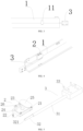
- a laptop includes a rotating shaft assembly, a display housing and a keyboard housing 5 according to an embodiment of the present disclosure.
- the rotating shaft assembly includes a camera assembly and a rotating shaft cover 1 according to an embodiment of the present disclosure.
- the camera assembly includes a mounting bracket and a camera unit 2.
- the mounting bracket is coupled to the display housing of the laptop, and the camera unit 2 is pivotally coupled to the mounting bracket.
- a first preset angle V1 an angle between an orientation of the camera unit 2 and the keyboard housing is maintained as a second preset angle V2.
- the rotating shaft cover 1 constitutes the mounting bracket for the camera assembly, i.e., the mounting bracket is the rotating shaft cover 1 of the laptop.
- the camera assembly is located on an inner side of the rotating shaft cover 1, and the mounting bracket of the camera assembly is coupled to the rotating shaft cover 1.
- the mounting bracket and the rotating shaft cover 1 have a common rotation axis, and the camera unit 2 is pivotally coupled to the rotating shaft cover 1, so that the camera unit 2 and the rotating shaft cover 1 can rotate relative to each other, and the camera unit 2 can adjust its shooting direction relative to the rotating shaft cover 1.
- the rotating shaft cover 1 is an arc-shaped plate and there is a cavity on the inner side of the rotating shaft cover 1.
- the rotating shaft cover 1 is entirely or at least partially made of a light-transmitting material, i.e., the rotating shaft cover 1 may be entirely light-transmitting, or may be light-transmitting only at a part of the rotating shaft cover 1 corresponding to a center of the camera unit 2.
- An inner wall surface of the rotating shaft cover 1 and the keyboard housing 5 form a mounting cavity, or the rotating shaft cover 1 has a mounting cavity.
- the camera unit 2 can be arranged in the mounting cavity.
- a direction of rotation of the display housing from a closed state (the opening-closing angle between the display housing and the keyboard housing 5 is 0°) to an open state relative to the keyboard housing 5 is regarded as a clockwise direction.
- the clockwise rotation of the rotating shaft cover 1 (the mounting bracket) coupled to the display housing can increase the opening-closing angle of the display housing.
- the angle between the orientation of the camera unit 2 and the keyboard housing 5 is the second preset angle V2.
- the camera unit 2 rotates counterclockwise around a rotation axis of the camera unit 2 while the rotating shaft cover 1 continues to rotate clockwise, and at the same time, a clockwise rotation angle of the rotating shaft cover 1 is equal to a counterclockwise rotation angle of the camera unit 2 around the rotation axis of the camera unit 2.
- the angle between the orientation of the camera unit 2 and the keyboard housing 5 can be kept as the second preset angle V2 when the opening-closing angle of the display housing is greater than the first preset angle V1.
- the opening-closing angle of the display housing may be an angle at which the display housing rotates around the rotation axis of the display housing, but is not limited thereto.
- the rotating shaft assembly according to the embodiment of the present disclosure and the camera assembly according to the embodiment of the present disclosure are fixed to the display housing by the mounting bracket, and the camera unit 2 is pivotally coupled to the mounting bracket; when the opening-closing angle of the display housing is greater than the first preset angle V1, the angle between the orientation of the camera unit 2 and the keyboard housing 5 is maintained as the second preset angle V2, so that the camera unit 2 can have a predetermined orientation after the mounting bracket and the display housing coupled to the mounting bracket are rotated by a certain angle.
- the rotating shaft assembly according to the embodiment of the present disclosure and the camera assembly according to the embodiment of the present disclosure have the advantage that the camera unit 2 can be oriented in a preset direction after the mounting bracket is rotated by a certain angle.
- the display housing is coupled to the rotating shaft cover 1 of the rotating shaft assembly, and the display housing is pivotally coupled to the keyboard housing 5 through the rotating shaft cover 1.
- the keyboard housing 5 may be substantially as a flat plate, a plane where the flat plate is may be used as a first datum surface, and there is an angle between the display housing and the first datum surface when the mounting bracket is rotated.
- the laptop according to the embodiment of the present disclosure can allow the angle between the orientation of the camera unit 2 of the camera assembly and the keyboard housing 5 to be kept at the second preset angle V2 when the opening-closing angle of the display housing relative to the keyboard housing 5 is greater than the first preset angle V1, by providing the rotating shaft assembly according to the embodiment of the present disclosure.
- the opening-closing angle of the display housing relative to the keyboard housing 5 is greater than the first preset angle V1
- a user can view a display normally.
- the fact that the angle between the orientation of the camera unit 2 and the keyboard housing 5 is maintained as the second preset angle V2 means that an angle between the shooting direction of the camera unit 2 and the keyboard housing 5 is V2.
- the angle between the shooting direction of the camera unit 2 and the keyboard housing 5 is V2
- it is convenient for the camera unit 2 to conduct camera shooting the user experience is excellent.
- the opening-closing angle of the display housing is greater than the first preset angle V1
- the angle between the orientation of the camera unit 2 and the keyboard housing 5 is maintained as the second preset angle V2. That is, when the user can normally view the display and rotates the display housing, the angle between the orientation of the camera unit 2 and the keyboard housing 5 remains unchanged, and the angle between the orientation of the camera unit 2 and the keyboard housing 5 is maintained at a value convenient for the camera unit 2 to conduct camera shooting, improving the user experience.
- the camera unit 2 by arranging the camera unit 2 on the inner side of the rotating shaft cover 1 (the mounting cavity inside the rotating shaft cover 1), the angle between the orientation of the camera unit 2 and the keyboard housing 5 can be guaranteed when the user views the display.
- the camera unit 2 can conduct camera shooting successfully without need to be arranged on the top side, improving the screen-to-body ratio of the display and the user experience.
- the arrangement of the camera unit 2 on the inner side of the rotating shaft cover 1 is less technically difficult and has a simple structure, i.e., low design difficulty and low cost.
- a distance between the camera unit 2 and the user is shorter when the camera unit 2 is arranged on the keycap of the keyboard, but the position of the camera unit 2 in relation to the user is more appropriate when the camera unit 2 is arranged on the inner side of the rotating shaft cover 1, which allows a better field of view of the camera unit 2 for camera shooting and improves the user experience.
- the laptop according to the embodiment of the present disclosure has the advantages of high screen-to-body ratio, low design difficulty, low cost and excellent user experience.
- the camera assembly further includes an adjustment member 3 coupled to the camera unit 2 to facilitate driving the camera unit 2 to rotate relative to the mounting bracket. Specifically, during the rotation of the mounting bracket, when the opening-closing angle of the display housing is greater than the first preset angle V1, the adjustment member 3 drives the camera unit 2 to rotate around the rotation axis of the camera unit 2, and a rotation direction of the camera unit 2 is opposite to a rotation direction of the mounting bracket.
- a rotation angle of the mounting bracket around the rotation axis of the display housing is equal to a rotation angle of the camera unit 2 around the rotation axis of the camera unit 2, so that the angle between the orientation of the camera unit 2 and the keyboard housing 5 can be maintained as the second preset angle V2.
- the rotating shaft cover 1 has a through-hole 11, and the through-hole 11 penetrates the rotating shaft cover 1 and is in communication with the mounting cavity, allowing the through-hole 11 to serve as a light transmission opening of the rotating shaft cover 1.
- a camera 23 of the camera unit 2 is oriented towards the through-hole 11 and photographs the environment outside the rotating shaft cover 1.
- the camera unit 2 of the camera assembly includes a transparent plate 25, which is bonded to the rotating shaft cover 1 and closes the through-hole 11.
- the transparent plate 25 is light-transmitting and closes the through-hole 11 to prevent dust and other debris from passing through the through-hole and affecting the shooting of the camera 23.
- the adjustment member 3 includes a connection segment 31 and a camshaft segment 32, which are coupled sequentially. Specifically, the connection segment 31 and the camshaft segment 32 are coupled along an extension direction of the rotating shaft cover 1.
- the connection segment 31 is coupled to the keyboard housing 5, i.e., the camshaft segment 32 is fixed to the keyboard housing 5 along with the connection segment 31, so that the camshaft segment 32 does not move with the rotation of the display housing.
- An axis of the camshaft segment 32, the rotation axis of the display housing relative to the keyboard housing 5 and the rotation axis of the camera unit 2 relative to the mounting bracket are parallel to one another, allowing the camshaft segment 32 and the rotating shaft cover 1 to jointly change the angle between the camera unit 2 and the keyboard housing 5.
- the rotation axis of the display housing and a rotation axis of the rotating shaft cover 1 are co-linear.
- the camera unit 2 is pivotally coupled to the rotating shaft cover 1 by a fixing pin 26 at a first end 201 of the camera unit, and the rotation axis of the camera unit 2 is a rotation axis of the fixing pin 26.
- a guide surface 321 of the camshaft segment 32 supports the camera unit 2.
- the guide surface 321 of the camshaft segment 32 is an upper end surface of the camshaft segment 32, and the guide surface 321 of the camshaft segment 32 supports the camera unit 2 upwardly.
- An up-down direction is indicated by arrow A in FIG. 5 .
- a second end 202 of the camera unit 2 is slidably coupled to the guide surface 321 of the camshaft segment 32, and the second end 202 of the camera unit 2 is opposite to the first end 201 of the camera unit 2.
- the fixing pin 26 at the first end 201 of the camera unit 2 is pivotally coupled to the rotating shaft cover 1, to enable the first end 201 of the camera unit 2 to rotate about the rotation axis of the display housing as the rotating shaft cover 1 rotates.
- the second end 202 of the camera unit 2 slides on the guide surface 321 of the camshaft segment 32, that is, the guide surface 321 of the camshaft segment 32 can limit a movement trajectory of the second end 202 of the camera unit 2.
- the adjustment member 3 can drive the camera unit 2 to rotate relative to the rotating shaft cover 1, maintaining the angle between the orientation of the camera unit 2 and the keyboard housing 5 at the second preset angle V2.
- the adjustment member 3 has a simple structure and is easier to arrange by providing the connection segment 31 and the camshaft segment 32.
- a central axis of the first guide surface 3211 is co-linear with the rotation axis of the display housing, and the first guide surface 3211 is coupled to the camera unit 2 when the display housing rotates around the rotation axis of the display housing and the rotation angle is smaller than the first preset angle V1.
- the first guide surface 3211 is a circular arc surface, and it is readily understood that a central axis of an arc surface formed by a trajectory of movement of the first end 201 of the camera unit 2 on the first guide surface 3211 is also co-linear with the rotation axis of the display housing when the display housing is rotated around the rotation axis of the display housing relative to the keyboard housing 5.
- a radian by which the camera unit 2 rotates along the first guide surface 3211 is equal to a radian by which the display housing rotates around the rotation axis of the display housing.
- the display housing rotates relative to the keyboard housing 5 around the rotation axis of the display housing up to the first preset angle V1
- the angle between the orientation of the camera unit 2 and the keyboard housing 5 reaches the second preset angle V2.
- the second end 202 of the camera unit 2 moves to a joint of the first guide surface 3211 and the second guide surface 3212.
- the second guide surface 3212 supports the camera unit 2, and the center of the camera unit 2 rotates around the rotation axis of the camera unit 2 by an angle equal to the rotation angle of the display housing around the rotation axis of the display housing.
- the rotation axis of the camera unit 2 is a central axis of the fixing pin.
- the second guide surface 3212 is a curved surface, and as the camera unit 2 rotates along the second guide surface 3212, an arc line along which the camera unit 2 rotates along the second guide surface 3212 satisfies: an angle at which the center of the camera unit 2 rotates around the rotation axis of the camera unit 2 is equal to an angle at which the display housing rotates around the rotation axis of the display housing.
- a rotation axis of each segment of the arc of the second guide surface 3212 and a rotation axis of the first guide surface 3211 are parallel to each other and are not co-linear.
- FIG. 7 when the display housing rotates relative to the keyboard housing 5 around the rotation axis of the display housing by an angle greater than the first preset angle V1 and continues to rotate, its moving state is shown in FIG. 7 , in which O represents the rotation axis of the display housing; L and L1 represent two positions of the display housing before and after the display housing rotates by an angle ⁇ , respectively; M and M1 represent two positions of the camera unit 2 before and after the camera unit rotates by the angle ⁇ , respectively; and M' and M are parallel to each other.
- the camera unit 2 is provided with a roller 21, and the camera unit 2 is in rolling cooperation with the guide surface 321 through the roller 21.
- the roller 21 is rotatably arranged at a lower part of the second end 202 of the camera unit 2, so that the roller 21 can be in rolling cooperation with the guide surface 321, reducing the wear of the camera unit 2 and improving the accuracy of the orientation of the camera unit 2.
- connection segment 31 is threadedly coupled to the keyboard housing 5 by means of a threaded member 33.
- a threaded member 33 an end of the connection segment 31 away from the camshaft segment 32 is a connection plate, and the connection plate has four connection holes, the keyboard housing 5 has four threaded holes, and the threaded member 33 is a bolt. Four bolts pass through the corresponding connection holes and are in thread fit with the corresponding threaded holes, facilitating connection between the connection segment and the keyboard housing 5.
- the laptop also includes an elastic member 4 that couples the rotating shaft cover 1 to the camera unit 2, and the elastic member 4 is used to press the camera unit 2 against the guide surface 321. Specifically, the elastic member 4 presses the camera unit 2 downwardly toward the camshaft segment 32, making the camera unit 2 more stable when moving along the guide surface 321 of the camshaft segment 32, and avoiding shaking of the camera unit 2 to ensure its use performance.
- the elastic member includes a spring 4 having a first end coupled to the camera unit 2 and a second end coupled to the rotating shaft cover 1.
- a lower end of the spring 4 is coupled to the camera unit 2 and an upper end of the spring 4 is coupled to the rotating shaft cover 1, such that the spring 4 can use its own elasticity to press the camera unit 2 downwardly toward the camshaft segment 32.
- the elastic member may be a torsion spring fitted over the fixing pin.
- the camera unit 2 includes a holding box 22, a camera 23, and a control board 24.
- the holding box 22 has a groove with an upward opening, and the camera 23 and the control board 24 are arranged in sequence from top to bottom in the groove of the holding box 22.
- the holding box 22 is pivotally coupled to the rotating shaft cover 1.
- the fixing pin 26 on the holding box 22 is pivotally coupled to the rotating shaft cover 1, and the camera unit 2 is pivotally coupled to the rotating shaft cover 1.
- the camera 23 is mounted on the control board 24, and the control board 24 is bonded in the holding box 22 by a double-sided adhesive, so that the camera 23 and the control board 24 can be fixed in the holding box 22.
- the first preset angle V1 ranges from 90° to 100° and the second preset angle V2 ranges from 65° to 75°. That is, when the opening-closing angle of the display housing is greater than the first preset angle (90°-100°), the adjustment member 3 can drive the camera unit 2 to rotate relative to the rotating shaft cover 1, to maintain the angle between the orientation of the camera unit 2 and the keyboard housing 5 at the second preset angle (65°-75°). When the opening-closing angle of the display housing is greater than the first preset angle (90°-100°), the user can view the display normally. When the angle between the camera orientation of the camera unit 2 and the keyboard housing 5 is 65°-75°, it is easy for the camera unit 2 to conduct camera shooting and the user experience is excellent.
- the first preset angle V1 is 90° and the second preset angle V2 is 70°.
- the opening-closing angle of the display housing reaches at least 90°, which is suitable for most users to view the display normally.
- the angle between the shooting direction of the camera unit 2 and the keyboard housing 5 is 70 °, the camera unit 2 can conduct the camera shooting easily, which satisfies the shooting needs of most users.
- first and second are used herein for purposes of description and are not intended to indicate or imply relative importance or the number of indicated technical features.
- the feature defined with “first” and “second” may include one or more this feature.
- a plurality of means at least two (e.g., two or three), unless specified otherwise.
- the terms “mounted,” “connected,” “coupled,” “fixed” and the like are used broadly, and may be, for example, fixed connections, detachable connections, or integral connections; may also be mechanical or electrical connections; may also communicate with each other; may also be direct connections or indirect connections via intervening structures; may also be inner connection or mutual interaction of two elements, which can be understood by those skilled in the art according to specific situations.
- a structure in which a first feature is "on" or “below” a second feature may include an embodiment in which the first feature is in direct contact with the second feature, and may also include an embodiment in which the first feature and the second feature are not in direct contact with each other, but are contacted via an additional feature formed therebetween.
- a first feature "on,” “above,” or “on top of” a second feature may include an embodiment in which the first feature is right or obliquely “on,” “above,” or “on top of” the second feature, or just means that the first feature is at a height higher than that of the second feature; while a first feature “below,” “under,” or “on bottom of” a second feature may include an embodiment in which the first feature is right or obliquely “below,” “under,” or “on bottom of” the second feature, or just means that the first feature is at a height lower than that of the second feature.
Landscapes
- Engineering & Computer Science (AREA)
- Computer Hardware Design (AREA)
- Theoretical Computer Science (AREA)
- Physics & Mathematics (AREA)
- General Physics & Mathematics (AREA)
- Human Computer Interaction (AREA)
- General Engineering & Computer Science (AREA)
- Multimedia (AREA)
- Signal Processing (AREA)
- Mathematical Physics (AREA)
- Studio Devices (AREA)
- Casings For Electric Apparatus (AREA)
Claims (14)
- Ein Laptop, umfassend ein Anzeigegehäuse, ein Tastaturgehäuse (5) und eine Kameraanordnung,
wobei die Kameraanordnung umfasst:eine Halterung, die mit dem Anzeigegehäuse gekoppelt ist;eine Kameraeinheit (2), die schwenkbar mit der Halterung gekoppelt ist; undein Einstellelement (3), das mit dem Tastaturgehäuse (5) gekoppelt ist und ein Verbindungssegment (31) sowie ein Nockenwellensegment (32), die nacheinander gekoppelt sind, umfasst, wobei das Verbindungssegment (31) mit dem Tastaturgehäuse (5) gekoppelt ist,wobei eine Achse des Nockenwellensegments (32), eine Rotationsachse des Anzeigegehäuses relativ zum Tastaturgehäuse (5) und eine Rotationsachse der Kameraeinheit (2) relativ zur Halterung zueinander parallel sind;eine Führungsfläche (321) des Nockenwellensegments (32) stützt die Kameraeinheit (2), und die Kameraeinheit (2) ist relativ zur Führungsfläche (321) beweglich;dadurch gekennzeichnet, dass:die Führungsfläche (321) eine erste Führungsfläche (3211) und eine zweite Führungsfläche (3212) umfasst, die nacheinander gekoppelt sind;wenn ein Öffnungs-Schließ-Winkel des Anzeigegehäuses relativ zum Tastaturgehäuse (5) kleiner als ein erster voreingestellter Winkel V1 ist, stützt die erste Führungsfläche (3211) die Kameraeinheit (2), und die Kameraeinheit (2) rotiert entlang der ersten Führungsfläche (3211) in derselben Richtung wie eine Rotationsrichtung der Halterung; undwenn der Öffnungs-Schließ-Winkel des Anzeigegehäuses relativ zum Tastaturgehäuse (5) größer als der erste voreingestellte Winkel V1 ist, stützt die zweite Führungsfläche (3212) die Kameraeinheit (2), und die Kameraeinheit (2) rotiert entlang der zweiten Führungsfläche (3212) in entgegengesetzter Richtung zur Rotationsrichtung der Halterung, sodass ein Winkel zwischen einer Ausrichtung der Kameraeinheit (2) und dem Tastaturgehäuse (5) als ein zweiter voreingestellter Winkel V2 beibehalten wird. - Der Laptop nach Anspruch 1, wobei das Einstellelement (3) die Kameraeinheit (2) dazu antreibt, relativ zur Halterung zu rotieren, wenn der Öffnungs-Schließ-Winkel des Anzeigegehäuses relativ zum Tastaturgehäuse (5) des Laptops größer als der erste voreingestellte Winkel V1 ist.
- Der Laptop nach Anspruch 1, wobei:eine Mittelachse der ersten Führungsfläche (3211) ko-linear mit der Rotationsachse des Anzeigegehäuses ist;die erste Führungsfläche (3211) die Kameraeinheit (2) stützt, wenn das Anzeigegehäuse um die Rotationsachse des Anzeigegehäuses rotiert und ein Rotationswinkel kleiner als der erste voreingestellte Winkel V1 ist; unddie zweite Führungsfläche (3212) die Kameraeinheit (2) stützt, wenn das Anzeigegehäuse um die Rotationsachse des Anzeigegehäuses rotiert und der Rotationswinkel größer als der erste voreingestellte Winkel V1 ist, und ein Mittelpunkt der Kameraeinheit (2) um die Rotationsachse der Kameraeinheit (2) um einen Winkel rotiert, der dem Rotationswinkel des Anzeigegehäuses um die Rotationsachse des Anzeigegehäuses entspricht.
- Der Laptop nach Anspruch 3, wobei:die erste Führungsfläche (3211) eine Kreisbogenfläche ist, und wenn die Kameraeinheit (2) entlang der ersten Führungsfläche (3211) rotiert, ein Bogenmaß, um das die Kameraeinheit (2) entlang der ersten Führungsfläche (3211) rotiert, gleich einem Bogenmaß ist, um das das Anzeigegehäuse um die Rotationsachse des Anzeigegehäuses rotiert; unddie zweite Führungsfläche (3212) eine gekrümmte Fläche ist, und wenn die Kameraeinheit (2) entlang der zweiten Führungsfläche (3212) rotiert, eine Bogenlinie, entlang der die Kameraeinheit (2) entlang der zweiten Führungsfläche (3212) rotiert, Folgendes erfüllt: ein Winkel, um den sich der Mittelpunkt der Kameraeinheit (2) um die Rotationsachse der Kameraeinheit (2) rotiert, ist gleich einem Winkel, um den sich das Anzeigegehäuse um die Rotationsachse des Anzeigegehäuses rotiert.
- Der Laptop nach einem der Ansprüche 1 bis 4, wobei die Kameraeinheit (2) eine Rolle (21) umfasst, und die Kameraeinheit (2) über die Rolle (21) in rollender Zusammenarbeit mit der Führungsfläche (321) steht.
- Der Laptop nach einem der Ansprüche 1 bis 5, wobei das Verbindungssegment (31) über ein Gewindeelement (33) gewindemäßig mit dem Tastaturgehäuse (5) gekoppelt ist.
- Der Laptop nach einem der Ansprüche 1 bis 6, wobei der Laptop ferner ein elastisches Element (4) umfasst, und das elastische Element (4) die Halterung mit der Kameraeinheit (2) koppelt und die Kameraeinheit (2) gegen die Führungsfläche (321) drückt.
- Der Laptop nach Anspruch 7, wobei das elastische Element (4) eine Feder umfasst, die ein erstes Ende (201) umfasst, das mit der Kameraeinheit (2) gekoppelt ist, und ein zweites Ende (202), das mit der Halterung gekoppelt ist.
- Der Laptop nach einem der Ansprüche 1 bis 8, wobei die Kameraeinheit (2) umfasst:eine Haltebox (22), die schwenkbar mit der Halterung gekoppelt ist;eine Steuerplatine (24), die in der Haltebox (22) befestigt ist; undeine Kamera (23), die an der Steuerplatine (24) montiert ist.
- Der Laptop nach einem der Ansprüche 1 bis 9, wobei der erste voreingestellte Winkel V1 im Bereich von 90° bis 100° liegt und der zweite voreingestellte Winkel V2 im Bereich von 65° bis 75° liegt.
- Der Laptop nach Anspruch 10, wobei der erste voreingestellte Winkel V1 90° beträgt und der zweite voreingestellte Winkel V2 70° beträgt.
- Der Laptop nach einem der Ansprüche 1 bis 11, ferner umfassend eine Rotationswellenabdeckung (1),
wobei:die Rotationswellenabdeckung (1) die Halterung der Kameraanordnung bildet; oderdie Kameraanordnung an einer Innenseite der Rotationswellenabdeckung (1) angeordnet ist, und die Halterung der Kameraanordnung mit der Rotationswellenabdeckung (1) gekoppelt ist. - Der Laptop nach Anspruch 12, wobei:die Rotationswellenabdeckung (1) ein Durchgangsloch (11) umfasst;die Kameraeinheit (2) der Kameraanordnung eine transparente Platte umfasst; unddie transparente Platte an der Rotationswellenabdeckung (1) befestigt ist und das Durchgangsloch verschließt.
- Der Laptop nach Anspruch 12 oder 13, wobei:das Anzeigegehäuse mit der Rotationswellenabdeckung (1) gekoppelt ist; unddas Tastaturgehäuse (5) schwenkbar über die Rotationswellenabdeckung (1) mit dem Anzeigegehäuse gekoppelt ist.
Applications Claiming Priority (1)
| Application Number | Priority Date | Filing Date | Title |
|---|---|---|---|
| CN202111161853.XA CN115904001A (zh) | 2021-09-30 | 2021-09-30 | 摄像头组件、转轴组件和笔记本电脑 |
Publications (2)
| Publication Number | Publication Date |
|---|---|
| EP4160352A1 EP4160352A1 (de) | 2023-04-05 |
| EP4160352B1 true EP4160352B1 (de) | 2025-06-04 |
Family
ID=80034839
Family Applications (1)
| Application Number | Title | Priority Date | Filing Date |
|---|---|---|---|
| EP22153445.6A Active EP4160352B1 (de) | 2021-09-30 | 2022-01-26 | Kameraanordnung, drehwellenanordnung und laptop |
Country Status (5)
| Country | Link |
|---|---|
| US (1) | US11956523B2 (de) |
| EP (1) | EP4160352B1 (de) |
| JP (1) | JP7461393B2 (de) |
| KR (1) | KR102842310B1 (de) |
| CN (1) | CN115904001A (de) |
Families Citing this family (3)
| Publication number | Priority date | Publication date | Assignee | Title |
|---|---|---|---|---|
| KR102902589B1 (ko) * | 2019-12-05 | 2025-12-22 | 엘지이노텍 주식회사 | 카메라 장치 |
| CN220121069U (zh) * | 2022-05-20 | 2023-12-01 | 台湾东电化股份有限公司 | 光学元件驱动机构 |
| CN117032401B (zh) * | 2023-10-09 | 2024-01-23 | 深圳市普斯德光电有限公司 | 一种笔记本电脑摄像头的翻转机构 |
Family Cites Families (12)
| Publication number | Priority date | Publication date | Assignee | Title |
|---|---|---|---|---|
| JP3545915B2 (ja) * | 1997-09-24 | 2004-07-21 | シャープ株式会社 | 電子機器 |
| ES2267697T3 (es) * | 2000-10-13 | 2007-03-16 | Lg Electronics Inc. | Aparato para ajustar automaticamente el angulo de un dispositivo de toma de imagenes. |
| JP2010028368A (ja) | 2008-07-17 | 2010-02-04 | Fujitsu Ltd | 電子機器 |
| JP2011076267A (ja) * | 2009-09-29 | 2011-04-14 | Nec Personal Products Co Ltd | 情報処理装置、資料撮影方法、プログラム及び記録媒体 |
| JP5621609B2 (ja) * | 2011-01-18 | 2014-11-12 | 株式会社リコー | チルト調整機構 |
| JP2015038655A (ja) | 2011-03-28 | 2015-02-26 | 株式会社東芝 | 電子機器 |
| JP6068545B2 (ja) | 2015-04-08 | 2017-01-25 | レノボ・シンガポール・プライベート・リミテッド | 携帯型情報処理装置、その撮影方法、及びコンピュータが実行可能なプログラム |
| CN110268319A (zh) | 2017-04-17 | 2019-09-20 | 惠普发展公司,有限责任合伙企业 | 相机系统外壳 |
| TWI672577B (zh) | 2018-04-17 | 2019-09-21 | 宏碁股份有限公司 | 筆記型電腦 |
| CN109992048B (zh) * | 2019-03-27 | 2020-09-25 | 广东虹勤通讯技术有限公司 | 一种电子设备 |
| CN209767654U (zh) * | 2019-05-31 | 2019-12-10 | 东莞裕勤通讯技术有限公司 | 用于电子设备的摄像头装置及电子设备 |
| CN212135291U (zh) * | 2020-06-30 | 2020-12-11 | 浪潮电子信息产业股份有限公司 | 一种做在转轴盖上的摄像头 |
-
2021
- 2021-09-30 CN CN202111161853.XA patent/CN115904001A/zh active Pending
-
2022
- 2022-01-25 KR KR1020220010614A patent/KR102842310B1/ko active Active
- 2022-01-26 US US17/585,160 patent/US11956523B2/en active Active
- 2022-01-26 EP EP22153445.6A patent/EP4160352B1/de active Active
- 2022-01-28 JP JP2022011939A patent/JP7461393B2/ja active Active
Also Published As
| Publication number | Publication date |
|---|---|
| US20230101960A1 (en) | 2023-03-30 |
| US11956523B2 (en) | 2024-04-09 |
| EP4160352A1 (de) | 2023-04-05 |
| CN115904001A (zh) | 2023-04-04 |
| JP2023051673A (ja) | 2023-04-11 |
| KR102842310B1 (ko) | 2025-08-07 |
| KR20230046927A (ko) | 2023-04-06 |
| JP7461393B2 (ja) | 2024-04-03 |
Similar Documents
| Publication | Publication Date | Title |
|---|---|---|
| EP4160352B1 (de) | Kameraanordnung, drehwellenanordnung und laptop | |
| US11281261B2 (en) | Hinge module and electronic device using the same | |
| US9189032B2 (en) | Rotary mechanism and related electronic device | |
| US8161604B2 (en) | 360° Bi-directional rotary hinge | |
| CN103576764B (zh) | 滑盖式电子装置及其线性移动机构 | |
| WO2019035833A1 (en) | TWO AXIS HINGE ASSEMBLY FOR ELECTRONIC DEVICES | |
| US11079062B2 (en) | Display device | |
| US20130127730A1 (en) | Portable Computer | |
| EP2687941B1 (de) | Zusammenklappbare elektronische Ausrüstung | |
| CN104179792B (zh) | 枢纽机构及电子装置 | |
| JPWO2021210075A5 (de) | ||
| US7396233B2 (en) | Display | |
| CN101378640A (zh) | 可调整倾斜角度及水平旋转角度的机构 | |
| CN217784006U (zh) | 一种旋转枢纽和电子设备 | |
| JP2004029953A (ja) | 支持機構 | |
| CN110213410B (zh) | 终端设备 | |
| JP4917517B2 (ja) | スライド回転取付ユニット及び携帯電話機 | |
| US20220107672A1 (en) | Electronic devices with hinge assemblies | |
| CN222281141U (zh) | 一种便于调节上盖角度的笔记本电脑 | |
| CN223434975U (zh) | 电子设备及其屏幕翻转装置 | |
| KR20020081723A (ko) | 영상표시기기의 힌지 보조 기구 구조 | |
| KR20010108910A (ko) | 각도 조절과 높이 조절이 동시에 이루어지는 엘시디모니터 스탠드 지지구조. | |
| TWM666632U (zh) | 樞軸機構 | |
| KR200402929Y1 (ko) | 핸드폰용 힌지 | |
| JP5221108B2 (ja) | スライド回転取付ユニット及び携帯電話機 |
Legal Events
| Date | Code | Title | Description |
|---|---|---|---|
| PUAI | Public reference made under article 153(3) epc to a published international application that has entered the european phase |
Free format text: ORIGINAL CODE: 0009012 |
|
| STAA | Information on the status of an ep patent application or granted ep patent |
Free format text: STATUS: REQUEST FOR EXAMINATION WAS MADE |
|
| 17P | Request for examination filed |
Effective date: 20220126 |
|
| AK | Designated contracting states |
Kind code of ref document: A1 Designated state(s): AL AT BE BG CH CY CZ DE DK EE ES FI FR GB GR HR HU IE IS IT LI LT LU LV MC MK MT NL NO PL PT RO RS SE SI SK SM TR |
|
| GRAP | Despatch of communication of intention to grant a patent |
Free format text: ORIGINAL CODE: EPIDOSNIGR1 |
|
| STAA | Information on the status of an ep patent application or granted ep patent |
Free format text: STATUS: GRANT OF PATENT IS INTENDED |
|
| INTG | Intention to grant announced |
Effective date: 20250103 |
|
| P01 | Opt-out of the competence of the unified patent court (upc) registered |
Free format text: CASE NUMBER: APP_8631/2025 Effective date: 20250220 |
|
| GRAS | Grant fee paid |
Free format text: ORIGINAL CODE: EPIDOSNIGR3 |
|
| GRAA | (expected) grant |
Free format text: ORIGINAL CODE: 0009210 |
|
| STAA | Information on the status of an ep patent application or granted ep patent |
Free format text: STATUS: THE PATENT HAS BEEN GRANTED |
|
| AK | Designated contracting states |
Kind code of ref document: B1 Designated state(s): AL AT BE BG CH CY CZ DE DK EE ES FI FR GB GR HR HU IE IS IT LI LT LU LV MC MK MT NL NO PL PT RO RS SE SI SK SM TR |
|
| REG | Reference to a national code |
Ref country code: GB Ref legal event code: FG4D |
|
| REG | Reference to a national code |
Ref country code: CH Ref legal event code: EP |
|
| REG | Reference to a national code |
Ref country code: DE Ref legal event code: R096 Ref document number: 602022015319 Country of ref document: DE |
|
| REG | Reference to a national code |
Ref country code: IE Ref legal event code: FG4D |
|
| REG | Reference to a national code |
Ref country code: NL Ref legal event code: MP Effective date: 20250604 |
|
| PG25 | Lapsed in a contracting state [announced via postgrant information from national office to epo] |
Ref country code: FI Free format text: LAPSE BECAUSE OF FAILURE TO SUBMIT A TRANSLATION OF THE DESCRIPTION OR TO PAY THE FEE WITHIN THE PRESCRIBED TIME-LIMIT Effective date: 20250604 Ref country code: ES Free format text: LAPSE BECAUSE OF FAILURE TO SUBMIT A TRANSLATION OF THE DESCRIPTION OR TO PAY THE FEE WITHIN THE PRESCRIBED TIME-LIMIT Effective date: 20250604 |
|
| REG | Reference to a national code |
Ref country code: LT Ref legal event code: MG9D |
|
| PG25 | Lapsed in a contracting state [announced via postgrant information from national office to epo] |
Ref country code: NO Free format text: LAPSE BECAUSE OF FAILURE TO SUBMIT A TRANSLATION OF THE DESCRIPTION OR TO PAY THE FEE WITHIN THE PRESCRIBED TIME-LIMIT Effective date: 20250904 Ref country code: GR Free format text: LAPSE BECAUSE OF FAILURE TO SUBMIT A TRANSLATION OF THE DESCRIPTION OR TO PAY THE FEE WITHIN THE PRESCRIBED TIME-LIMIT Effective date: 20250905 |
|
| PG25 | Lapsed in a contracting state [announced via postgrant information from national office to epo] |
Ref country code: PL Free format text: LAPSE BECAUSE OF FAILURE TO SUBMIT A TRANSLATION OF THE DESCRIPTION OR TO PAY THE FEE WITHIN THE PRESCRIBED TIME-LIMIT Effective date: 20250604 |
|
| PG25 | Lapsed in a contracting state [announced via postgrant information from national office to epo] |
Ref country code: BG Free format text: LAPSE BECAUSE OF FAILURE TO SUBMIT A TRANSLATION OF THE DESCRIPTION OR TO PAY THE FEE WITHIN THE PRESCRIBED TIME-LIMIT Effective date: 20250604 |
|
| PG25 | Lapsed in a contracting state [announced via postgrant information from national office to epo] |
Ref country code: HR Free format text: LAPSE BECAUSE OF FAILURE TO SUBMIT A TRANSLATION OF THE DESCRIPTION OR TO PAY THE FEE WITHIN THE PRESCRIBED TIME-LIMIT Effective date: 20250604 |
|
| PG25 | Lapsed in a contracting state [announced via postgrant information from national office to epo] |
Ref country code: RS Free format text: LAPSE BECAUSE OF FAILURE TO SUBMIT A TRANSLATION OF THE DESCRIPTION OR TO PAY THE FEE WITHIN THE PRESCRIBED TIME-LIMIT Effective date: 20250904 |
|
| PG25 | Lapsed in a contracting state [announced via postgrant information from national office to epo] |
Ref country code: LV Free format text: LAPSE BECAUSE OF FAILURE TO SUBMIT A TRANSLATION OF THE DESCRIPTION OR TO PAY THE FEE WITHIN THE PRESCRIBED TIME-LIMIT Effective date: 20250604 |
|
| PG25 | Lapsed in a contracting state [announced via postgrant information from national office to epo] |
Ref country code: NL Free format text: LAPSE BECAUSE OF FAILURE TO SUBMIT A TRANSLATION OF THE DESCRIPTION OR TO PAY THE FEE WITHIN THE PRESCRIBED TIME-LIMIT Effective date: 20250604 |
|
| PG25 | Lapsed in a contracting state [announced via postgrant information from national office to epo] |
Ref country code: PT Free format text: LAPSE BECAUSE OF FAILURE TO SUBMIT A TRANSLATION OF THE DESCRIPTION OR TO PAY THE FEE WITHIN THE PRESCRIBED TIME-LIMIT Effective date: 20251006 |
|
| REG | Reference to a national code |
Ref country code: AT Ref legal event code: MK05 Ref document number: 1800947 Country of ref document: AT Kind code of ref document: T Effective date: 20250604 |
|
| PG25 | Lapsed in a contracting state [announced via postgrant information from national office to epo] |
Ref country code: IS Free format text: LAPSE BECAUSE OF FAILURE TO SUBMIT A TRANSLATION OF THE DESCRIPTION OR TO PAY THE FEE WITHIN THE PRESCRIBED TIME-LIMIT Effective date: 20251004 |
|
| PGFP | Annual fee paid to national office [announced via postgrant information from national office to epo] |
Ref country code: GB Payment date: 20251204 Year of fee payment: 5 |
|
| PG25 | Lapsed in a contracting state [announced via postgrant information from national office to epo] |
Ref country code: AT Free format text: LAPSE BECAUSE OF FAILURE TO SUBMIT A TRANSLATION OF THE DESCRIPTION OR TO PAY THE FEE WITHIN THE PRESCRIBED TIME-LIMIT Effective date: 20250604 Ref country code: SM Free format text: LAPSE BECAUSE OF FAILURE TO SUBMIT A TRANSLATION OF THE DESCRIPTION OR TO PAY THE FEE WITHIN THE PRESCRIBED TIME-LIMIT Effective date: 20250604 |
|
| PG25 | Lapsed in a contracting state [announced via postgrant information from national office to epo] |
Ref country code: CZ Free format text: LAPSE BECAUSE OF FAILURE TO SUBMIT A TRANSLATION OF THE DESCRIPTION OR TO PAY THE FEE WITHIN THE PRESCRIBED TIME-LIMIT Effective date: 20250604 |
|
| PG25 | Lapsed in a contracting state [announced via postgrant information from national office to epo] |
Ref country code: EE Free format text: LAPSE BECAUSE OF FAILURE TO SUBMIT A TRANSLATION OF THE DESCRIPTION OR TO PAY THE FEE WITHIN THE PRESCRIBED TIME-LIMIT Effective date: 20250604 |
|
| PG25 | Lapsed in a contracting state [announced via postgrant information from national office to epo] |
Ref country code: SK Free format text: LAPSE BECAUSE OF FAILURE TO SUBMIT A TRANSLATION OF THE DESCRIPTION OR TO PAY THE FEE WITHIN THE PRESCRIBED TIME-LIMIT Effective date: 20250604 |
|
| PG25 | Lapsed in a contracting state [announced via postgrant information from national office to epo] |
Ref country code: IT Free format text: LAPSE BECAUSE OF FAILURE TO SUBMIT A TRANSLATION OF THE DESCRIPTION OR TO PAY THE FEE WITHIN THE PRESCRIBED TIME-LIMIT Effective date: 20250604 |
|
| REG | Reference to a national code |
Ref country code: DE Ref legal event code: R097 Ref document number: 602022015319 Country of ref document: DE |
|
| PLBE | No opposition filed within time limit |
Free format text: ORIGINAL CODE: 0009261 |
|
| STAA | Information on the status of an ep patent application or granted ep patent |
Free format text: STATUS: NO OPPOSITION FILED WITHIN TIME LIMIT |
|
| PG25 | Lapsed in a contracting state [announced via postgrant information from national office to epo] |
Ref country code: DK Free format text: LAPSE BECAUSE OF FAILURE TO SUBMIT A TRANSLATION OF THE DESCRIPTION OR TO PAY THE FEE WITHIN THE PRESCRIBED TIME-LIMIT Effective date: 20250604 |
|
| REG | Reference to a national code |
Ref country code: CH Ref legal event code: L10 Free format text: ST27 STATUS EVENT CODE: U-0-0-L10-L00 (AS PROVIDED BY THE NATIONAL OFFICE) Effective date: 20260416 |