EP4160243B1 - Détermination des positions d'essai pour une mesure d'essai à enregistrer par un système de résonance magnétique - Google Patents
Détermination des positions d'essai pour une mesure d'essai à enregistrer par un système de résonance magnétique Download PDFInfo
- Publication number
- EP4160243B1 EP4160243B1 EP21199777.0A EP21199777A EP4160243B1 EP 4160243 B1 EP4160243 B1 EP 4160243B1 EP 21199777 A EP21199777 A EP 21199777A EP 4160243 B1 EP4160243 B1 EP 4160243B1
- Authority
- EP
- European Patent Office
- Prior art keywords
- test
- positions
- test positions
- image
- magnetic resonance
- Prior art date
- Legal status (The legal status is an assumption and is not a legal conclusion. Google has not performed a legal analysis and makes no representation as to the accuracy of the status listed.)
- Active
Links
Images


Classifications
-
- G—PHYSICS
- G01—MEASURING; TESTING
- G01R—MEASURING ELECTRIC VARIABLES; MEASURING MAGNETIC VARIABLES
- G01R33/00—Arrangements or instruments for measuring magnetic variables
- G01R33/20—Arrangements or instruments for measuring magnetic variables involving magnetic resonance
- G01R33/44—Arrangements or instruments for measuring magnetic variables involving magnetic resonance using nuclear magnetic resonance [NMR]
- G01R33/48—NMR imaging systems
- G01R33/54—Signal processing systems, e.g. using pulse sequences ; Generation or control of pulse sequences; Operator console
- G01R33/543—Control of the operation of the MR system, e.g. setting of acquisition parameters prior to or during MR data acquisition, dynamic shimming, use of one or more scout images for scan plane prescription
-
- G—PHYSICS
- G01—MEASURING; TESTING
- G01R—MEASURING ELECTRIC VARIABLES; MEASURING MAGNETIC VARIABLES
- G01R33/00—Arrangements or instruments for measuring magnetic variables
- G01R33/20—Arrangements or instruments for measuring magnetic variables involving magnetic resonance
- G01R33/44—Arrangements or instruments for measuring magnetic variables involving magnetic resonance using nuclear magnetic resonance [NMR]
- G01R33/48—NMR imaging systems
- G01R33/54—Signal processing systems, e.g. using pulse sequences ; Generation or control of pulse sequences; Operator console
-
- G—PHYSICS
- G01—MEASURING; TESTING
- G01R—MEASURING ELECTRIC VARIABLES; MEASURING MAGNETIC VARIABLES
- G01R33/00—Arrangements or instruments for measuring magnetic variables
- G01R33/20—Arrangements or instruments for measuring magnetic variables involving magnetic resonance
- G01R33/44—Arrangements or instruments for measuring magnetic variables involving magnetic resonance using nuclear magnetic resonance [NMR]
- G01R33/48—NMR imaging systems
- G01R33/54—Signal processing systems, e.g. using pulse sequences ; Generation or control of pulse sequences; Operator console
- G01R33/56—Image enhancement or correction, e.g. subtraction or averaging techniques, e.g. improvement of signal-to-noise ratio and resolution
- G01R33/565—Correction of image distortions, e.g. due to magnetic field inhomogeneities
-
- G—PHYSICS
- G01—MEASURING; TESTING
- G01R—MEASURING ELECTRIC VARIABLES; MEASURING MAGNETIC VARIABLES
- G01R33/00—Arrangements or instruments for measuring magnetic variables
- G01R33/20—Arrangements or instruments for measuring magnetic variables involving magnetic resonance
- G01R33/44—Arrangements or instruments for measuring magnetic variables involving magnetic resonance using nuclear magnetic resonance [NMR]
- G01R33/48—NMR imaging systems
- G01R33/54—Signal processing systems, e.g. using pulse sequences ; Generation or control of pulse sequences; Operator console
- G01R33/56—Image enhancement or correction, e.g. subtraction or averaging techniques, e.g. improvement of signal-to-noise ratio and resolution
- G01R33/561—Image enhancement or correction, e.g. subtraction or averaging techniques, e.g. improvement of signal-to-noise ratio and resolution by reduction of the scanning time, i.e. fast acquiring systems, e.g. using echo-planar pulse sequences
- G01R33/5611—Parallel magnetic resonance imaging, e.g. sensitivity encoding [SENSE], simultaneous acquisition of spatial harmonics [SMASH], unaliasing by Fourier encoding of the overlaps using the temporal dimension [UNFOLD], k-t-broad-use linear acquisition speed-up technique [k-t-BLAST], k-t-SENSE
-
- G—PHYSICS
- G01—MEASURING; TESTING
- G01R—MEASURING ELECTRIC VARIABLES; MEASURING MAGNETIC VARIABLES
- G01R33/00—Arrangements or instruments for measuring magnetic variables
- G01R33/20—Arrangements or instruments for measuring magnetic variables involving magnetic resonance
- G01R33/44—Arrangements or instruments for measuring magnetic variables involving magnetic resonance using nuclear magnetic resonance [NMR]
- G01R33/48—NMR imaging systems
- G01R33/54—Signal processing systems, e.g. using pulse sequences ; Generation or control of pulse sequences; Operator console
- G01R33/56—Image enhancement or correction, e.g. subtraction or averaging techniques, e.g. improvement of signal-to-noise ratio and resolution
- G01R33/565—Correction of image distortions, e.g. due to magnetic field inhomogeneities
- G01R33/56518—Correction of image distortions, e.g. due to magnetic field inhomogeneities due to eddy currents, e.g. caused by switching of the gradient magnetic field
-
- G—PHYSICS
- G01—MEASURING; TESTING
- G01R—MEASURING ELECTRIC VARIABLES; MEASURING MAGNETIC VARIABLES
- G01R33/00—Arrangements or instruments for measuring magnetic variables
- G01R33/20—Arrangements or instruments for measuring magnetic variables involving magnetic resonance
- G01R33/44—Arrangements or instruments for measuring magnetic variables involving magnetic resonance using nuclear magnetic resonance [NMR]
- G01R33/48—NMR imaging systems
- G01R33/54—Signal processing systems, e.g. using pulse sequences ; Generation or control of pulse sequences; Operator console
- G01R33/56—Image enhancement or correction, e.g. subtraction or averaging techniques, e.g. improvement of signal-to-noise ratio and resolution
- G01R33/565—Correction of image distortions, e.g. due to magnetic field inhomogeneities
- G01R33/56572—Correction of image distortions, e.g. due to magnetic field inhomogeneities caused by a distortion of a gradient magnetic field, e.g. non-linearity of a gradient magnetic field
Definitions
- the invention relates to a method for determining a PSF for a reconstruction of image data from measurement data recorded by means of a magnetic resonance system.
- Magnetic resonance technology (hereinafter the abbreviation MR stands for magnetic resonance) is a well-known technology with which images of the interior of an object under examination can be generated.
- the object under examination is positioned in a magnetic resonance device in a comparatively strong static, homogeneous basic magnetic field, also known as a B 0 field, with field strengths of 0.2 Tesla to 7 Tesla and more, so that its nuclear spins are oriented along the basic magnetic field.
- RF pulses high-frequency excitation pulses
- MR images are reconstructed or spectroscopy data are determined on this basis.
- a scheme used which describes a temporal sequence of RF pulses to be radiated and gradients to be switched, is referred to as a pulse sequence (scheme), or simply as a sequence.
- the recorded measurement data are digitized and stored as complex numerical values in a k-space matrix.
- An associated MR image can be reconstructed from the k-space matrix filled with values, for example using a multidimensional Fourier transformation.
- So-called parallel acquisition techniques such as GRAPPA ("GeneRalized Autocalibrating Partially Parallel Acquisition”) or SENSE ("Sensitivity Encoding"), in which only one RF coil is used according to the Nyquist theorem
- a subsampled number of measurement data can be recorded in k-space, for example to shorten the total measurement time required to record the measurement data or to increase the resolution.
- the "missing" measurement data ie data that was not measured but is required for a complete set of measurement data according to Nyquist, are supplemented on the basis of sensitivity data of the RF coils used and calibration data and the measured measurement data.
- the desire for ever faster MR recordings in the clinical environment is leading to a renaissance of methods in which several images are recorded simultaneously.
- these methods can be characterized by the fact that, at least during part of the measurement, the transverse magnetization of at least two slices is used simultaneously for the imaging process ("multi-slice imaging”, “slice multiplexing”, “simultaneous multi-slice” (SMS)).
- multi-slice imaging the signal from at least two slices is recorded alternately, i.e. completely independently of one another, with a correspondingly longer measurement time.
- Well-known SMS methods are, for example, methods that use methods from the above-mentioned imaging using ppa, in which knowledge about the sensitivity distribution of the receiving coils used to record the measurement data is used as additional information to fill in undersampled measurement data according to Nyquist, in the slice direction in order to separate superimposed signals recorded from several slices into signals from the individual slices.
- These procedures include, for example, the CAIPIRINHA technique, which by Breuer et al. in "Controlled Aliasing in Parallel Imaging Results in Higher Acceleration (CAIPIRINHA) for Multi-Slice Imaging", Magnetic Resonance in Medicine 53, 2005, pp. 684-691 and the blipped CAIPIRINHA technique as described by Setsompop et al.
- At least one sinusoidally modulated gradient is played out in a direction perpendicular to the readout direction during the readout process at the same time as a gradient in the readout direction.
- a wave- or helical k-space trajectory obtained in this way distributes artifacts, such as aliasing artifacts, which occur due to undersampling of the k-space used to shorten the measurement time, in at least two, or, for helical k-space trajectories, in all spatial directions, and thus makes it possible to use sensitivity data of the RF coils used in several (all three) spatial directions, which leads to the aforementioned reduction in the g-factor.
- higher accelerations i.e. stronger undersampling, can be applied, while maintaining the same Quality of the obtained image data compared to "non-wave-ppa techniques" with lower acceleration.
- Wave x y z F ⁇ 1 x PSF k x y z F x m x y z , where F x is a Fourier transform and F -1 x is the inverse Fourier transform and PSF(k x ,y,z) is the PSF for a wave gradient represented in the hybrid k x -yz space.
- the PSF describes the effect of the modulated gradients on the imaging phase in the k x direction and can be separated into terms that depend on y and z.
- aliasing artifacts can therefore be eliminated by "unaliasing" using a SENSE reconstruction. This is described in more detail in the article by Polak et al. “Highly-Accelerated Volumetric Brain Examination Using Optimized Wave-CAIPI Encoding,” J. Magn. Reason. Imaging 2019, 50:961-974 , described.
- the PSF of sinusoidally or cosinusoidally modulated gradients are also sinusoidal or cosinusoidal. Therefore, a modulation transfer function MTF obtained by a Fourier transformation of such a PSF should only have one frequency component.
- a spectrum of a real PSF described by an MTF is usually broadened by imperfections of the gradients used during the readout process, which can be caused by eddy currents and delays in the switched gradients, etc. Therefore, a reconstruction of image data that uses an ideal PSF leads to blurring in the reconstructed image data.
- wave techniques prove to be particularly sensitive to imperfections of the gradients used during the readout process, so that deviations of the gradients actually generated during a measurement during a readout period from the respective ideal gradients planned for this readout period lead to artifacts in the ultimately obtained image data.
- the invention is based on the object of improving methods which use test measurements at test positions of an object under investigation.
- the object is achieved by a method for determining at least one test position for a test measurement to be recorded by means of a magnetic resonance system according to claim 1, a magnetic resonance system according to claim 13, a computer program according to claim 14, and an electronically readable data carrier according to claim 15.
- the invention is based on the finding that in applications which require data from test measurements of a magnetic resonance system, an achievable result depends on the quality of the test positions selected for the test measurements in the target volume of the measurement.
- the inventive selection of test positions based on a test image can ensure that the test positions are in a recording area that is favorable for the test measurement, e.g. also within an examination object to be examined in the test image. This makes it possible to achieve a higher image quality in MR images that were generated using test measurements carried out at test positions positioned according to the invention.
- a magnetic resonance system comprises a magnet unit, a gradient unit, a radio frequency unit and a control device designed to carry out a method according to the invention with a test position determination unit.
- a computer program according to the invention implements a method according to the invention on a control device when it is executed on the control device.
- the computer program can also be in the form of a computer program product which can be loaded directly into a memory of a control device, with program code means for carrying out a method according to the invention when the computer program product is executed in the computing unit of the computing system.
- An electronically readable data carrier comprises electronically readable control information stored thereon, which comprises at least one computer program according to the invention and is designed such that it carries out a method according to the invention when the data carrier is used in a control device of a magnetic resonance system.
- Figure 1 is a schematic flow diagram of a method according to the invention for determining at least one test position for a test measurement to be recorded by means of a magnetic resonance system.
- test image B is recorded (block 101).
- the test image B can, for example, be a test image B reconstructed from data recorded during a pre-scan, in particular calibration data.
- Calibration data are often recorded in conjunction with MR measurements, e.g. to adjust measurement parameters. and/or coil sensitivity data, and generally have a lower resolution than measurement data recorded for diagnostic MR images. They can therefore be calculated quickly and require less storage space.
- test image B is an MR image reconstructed from measurement data recorded for a desired examination of an examination object.
- At least one test position P is selected (block 103).
- the selection of the at least one test position can be based on a first predetermined test grid that defines a number of test positions and their distribution pattern in a displayed target area of the test image B.
- the test grid can be, for example, a Cartesian test grid or a hexagonal test grid.
- the test grid can be fixed. It is also possible to define the test grid using a user input E.
- an assignment function M is determined which assigns test positions to permitted test positions (e.g. in favorable areas A2 of the test image) or blocked test positions (e.g. in unfavorable areas of the test image B) (block 101').
- the assignment function M is based on intensity values of the test image B and can, for example, take into account a minimum intensity value. Areas of the test image B that reach the minimum intensity value can be marked as favorable for positioning a test position, and areas of the test image B that do not reach the minimum intensity value can be marked as unfavorable for positioning a test position.
- a minimum intensity value can be fixed or set by a user input E.
- the assignment function M can be determined in the form of a binary mask which blocks test positions which lie in a region A1 of the test image B in which a minimum required intensity value is not reached, and which allows test positions which lie in a region A2 of the test image B in which a minimum required intensity value is reached.
- test positions located in unfavorable areas of the test image particularly areas with low intensity and thus noise
- the required computing time is simultaneously reduced in this way, since fewer test positions are allowed.
- the selection of test positions can also include weighting test positions according to a weighting factor that depends on an intensity value of the test image at a respective, in particular a permitted, test position.
- the weighting factor of a test position can depend directly proportionally on the intensity value present at the test position in the test image. However, it is also conceivable to select weighting factors in a staggered manner. For example, for all test positions that have an intensity value in the test image that is greater than or equal to a certain required intensity value of the test image B, e.g. a required intensity value determined according to the mean value or median as the mean intensity value, the weighting factor can be set to the value one.
- the weighting factor can be set to the value zero.
- the weighting factor can be set, for example, linearly or cubically or according to a (square) root function running from the value one to the value zero. Weighting with the weighting factor zero corresponds to blocking the test position.
- Such weighting can, for example, be easily implemented in an assignment function M, in particular in the form of a weighted mask.
- Such weighting can result in fewer test positions being blocked, while still reducing the influence of test positions positioned in less favorable areas of test image B.
- the use of more test positions can have a stabilizing effect (e.g. via averaging effects).
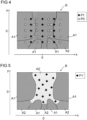
- Figure 2 shows a first exemplary distribution of test positions in a test image B.
- First test positions P1 are positioned according to a first test grid at predetermined coordinates in the two directions (here: x-direction and y-direction) of the test image B.
- the predetermined first test grid can uniformly cover the target volume of the test image B, or at least a central area of the test image B and/or an area in which the object to be examined is suspected to be located.
- test positions P1 shown as examples 7 are in an area A1 that is assessed as unfavorable, for example by an assignment function. These test positions in an area A1 that is assessed as unfavorable are blocked.
- Locked test positions for example those in Figure 2 in the first test positions P1 located in the area A1, However, they can also be moved to second test positions P2. Such second test positions P2 are in turn assigned to permitted (e.g. in the area A2) or blocked (in the area A1) test positions according to the assignment function.
- a shift of the first test positions P1 can be carried out row by row or column by column to the second test positions P2 for rows or columns of the first test grid. Such shifts are easy to calculate.
- the shift can be carried out in the manner of a binary search in order to achieve the most even distribution possible.
- Such a binary search can be achieved, for example, by initially shifting by half the distance between the grid point of a test position to be shifted and the nearest grid point in the direction of the image center of the first test grid, where the shifted test positions are again checked using the assignment function. If all or most of the test positions P1 to be shifted are in the favorable area A2, they can be shifted again, now in the opposite direction, for example by a quarter of half the distance between the grid point of the test position to be shifted and the nearest grid point, where the shifted test positions are again checked using the assignment function.
- test positions P1 to be shifted are in the favorable area A2, they can be shifted again, now in the opposite direction, for example by an eighth of half the distance between the grid point of the test position to be shifted and the nearest grid point. If there are fewer test positions P1 to be moved in the favorable area A2 than in the last test, the position can be moved again in the original direction, e.g. by one eighth of half the distance between the grid point of the test position to be moved and the nearest grid point.
- Figure 2 is shown as an example how first test positions P1 of a column of the test grid (ie with the same x-coordinate), which are at least partially, preferably predominantly, blocked (because they are in the area A1) can be moved to second test positions P2 (arrows).
- the moving preferably takes place in the direction of the image center of the test image B (in the direction of movement, here x-direction), so that with high probability a region A2 is reached that is classified as favorable.
- first test positions P1 of a column of the test grid ie with the same x-coordinate
- the moving preferably takes place in the direction of the image center of the test image B (in the direction of movement, here x-direction), so that with high probability a region A2 is reached that is classified as favorable.
- first test positions P1 of a column of the test grid ie with the same x-coordinate
- second test positions P2 arrows
- individual blocked first test positions P1 can be moved to second test positions P2 in at least one spatial direction (x, y) of the test image B in the direction of the image center (0, 0) of the test image B or to a second test position P2 with a desired intensity value in the test image B.
- This can ensure that all blocked first test positions P1 are moved to permitted second test positions P2.
- additional attention can be paid to the most even distribution possible of the permitted test positions P1 and P2 and/or to positioning the permitted test positions P1 and P2 in the favorable area A2 at positions with high intensity values.
- candidate test positions P0 can be positioned according to a second predetermined test grid, which is more tightly meshed than the first test grid.
- the candidate test positions P0 can in turn be positioned according to the assignment function M can be assigned to allowed or blocked test positions, and blocked first test positions can be moved to, e.g., spatially closest, allowed candidate positions.
- the second test grid can again evenly cover the test image B.
- the second test grid can encompass the first test grid and have a mesh size that corresponds to half the mesh size of the first test grid.
- the selection of test positions P1' comprises distributing a predetermined number of test positions P1' in an area A2 ⁇ permitted according to an approval criterion Z based on intensity values of the test image B.
- the approval criterion Z can, for example, define an approved area A2 ⁇ by means of a segmentation of the test image B such that the approved area depicts the object to be examined.
- the approval criterion Z can define a predetermined minimum intensity value that must be reached in the approved area A2.
- the approval criterion Z can also be an approval function M designed as a binary mask.
- a desired number of test positions P1' and/or a minimum intensity value can be fixed or determined by a user input E.
- test positions P1' are distributed in the approved area A2 ⁇ .
- the distribution of the test positions P1' can be carried out, for example, using a greedy algorithm that assigns the test positions to grid points of a given or selected (e.g. Cartesian or hexagonal) distribution grid.
- the distribution grid can have a distance between its grid points that corresponds to the distance between the grid points of a test grid.
- the distribution grid can be a test grid.
- the distribution of the test positions P1' can be carried out by means of a dynamic greedy algorithm, which distributes the test positions P1' not at fixed grid points of the distribution grid, but in circles around its grid points predetermined by a selected radius.
- distributing the test positions P1' can include finding a distribution equilibrium according to an "electron scattering" method, in which test positions P1' are each assigned a similar charge and an optimal distribution in the permitted area A2 is simulated according to electrical repulsion.
- a charge can also be assigned to an edge of the permitted area A2' or a suitable boundary condition can be used to prevent the test positions P1' from being arranged only along the edge of the permitted area A2'.
- boundary conditions can be, for example, periodic or toroidal boundary conditions that connect opposite edges of the permitted area A2' as if they were next to each other, thus dissolving the edges.
- Test measurements can be carried out at test positions selected according to the invention, which provide test results K (block 105).
- test positions can be determined for methods to compensate for effects of deviations of gradients actually generated during a readout period from gradients planned for that readout period.
- K PSF values can be measured as test results.
- test results can be used in the processing of further measurement data MD and/or image data BD recorded by means of the magnetic resonance system, in particular using a wave technique, whereby processed, in particular corrected measurement data MD* or image data BD* of high image quality are obtained (block 107).
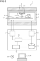
- FIG. 6 schematically shows a magnetic resonance system 1 according to the invention.
- This comprises a magnet unit 3 for generating the basic magnetic field, a gradient unit 5 for generating the gradient fields, a high-frequency unit 7 for irradiating and receiving high-frequency signals and a control device 9 designed to carry out a method according to the invention.
- the high-frequency unit 7 can consist of several subunits, for example of several coils such as the schematically shown coils 7.1 and 7.2 or more coils, which can be designed either only for transmitting high-frequency signals or only for receiving the triggered high-frequency signals or for both.
- the slice or slab S i represents an exemplary target volume of the object under investigation from which echo signals are to be recorded and recorded as measurement data.
- the control device 9 serves to control the magnetic resonance system 1 and can in particular control the gradient unit 5 by means of a gradient controller 5' and the radio frequency unit 7 by means of a radio frequency transmission/reception controller 7'.
- the radio frequency unit 7 can comprise several channels on which signals can be transmitted or received.
- the high-frequency unit 7, together with its high-frequency transmit/receive control 7', is responsible for generating and radiating (transmitting) a high-frequency alternating field for manipulating the spins in an area to be manipulated (for example in layers S to be measured) of the object under investigation U.
- the center frequency of the high-frequency alternating field also referred to as the B1 field, is generally set as close as possible to the resonance frequency of the spins to be manipulated. Deviations from the center frequency to the resonance frequency are referred to as off-resonance.
- controlled currents are applied to the RF coils in the high-frequency unit 7 by means of the high-frequency transmit/receive control 7'.
- control device 9 comprises a test position determination unit 15 with which test positions according to the invention can be determined.
- the control device 9 is designed overall to carry out a method according to the invention.
- a computing unit 13 included in the control device 9 is designed to carry out all the computing operations required for the necessary measurements and determinations. Intermediate results and results required for this purpose or determined in this process can be stored in a memory unit S of the control device 9.
- the units shown are not necessarily to be understood as physically separate units, but merely represent a subdivision into meaningful units, which can also be realized, for example, in fewer or even in only one single physical unit.
- control commands can be sent to the magnetic resonance system, e.g. by a user, and/or results of the control device 9, such as image data, can be displayed.
- a method described herein can also be in the form of a computer program product which comprises a program and implements the described method on a control device 9 when it is executed on the control device 9.
- an electronically readable data carrier 26 with electronically readable control information stored thereon can be present, which comprise at least one such computer program product just described and are designed such that they carry out the described method when the data carrier 26 is used in a control device 9 of a magnetic resonance system 1.
Landscapes
- Physics & Mathematics (AREA)
- Engineering & Computer Science (AREA)
- Signal Processing (AREA)
- High Energy & Nuclear Physics (AREA)
- Condensed Matter Physics & Semiconductors (AREA)
- General Physics & Mathematics (AREA)
- Health & Medical Sciences (AREA)
- General Health & Medical Sciences (AREA)
- Nuclear Medicine, Radiotherapy & Molecular Imaging (AREA)
- Radiology & Medical Imaging (AREA)
- Magnetic Resonance Imaging Apparatus (AREA)
Claims (14)
- Procédé de détermination d'au moins une position d'essai pour une mesure d'essai à enregistrer au moyen d'une installation de résonance magnétique comprenant les stades :- enregistrement d'une image (B) d'essai,- choix d'au moins une position (P, P1, P1', P2) d'essai sur la base de l'image (B) d'essai,dans lequel le choix de positions (P, P1, P1', P2) d'essai comprend une affectation de positions (P, P1, P1', P2) d'essai à des positions d'essai autorisées et à des positions d'essai interdites suivant une fonction (M) d'affectation reposant sur des valeurs d'intensité de l'image (B) d'essai à des positions (P, P1, P1', P2) d'essai.
- Procédé suivant la revendication 1, dans lequel des premières positions (P1) d'essai sont positionnées dans l'image (B) d'essai suivant une première grille d'essai donnée à l'avance.
- Procédé suivant la revendication 2, dans lequel la première grille d'essai donnée à l'avance recouvre uniformément un volume cible de l'image (B) d'essai.
- Procédé suivant l'une des revendications précédentes, dans lequel la fonction (M) d'affectation prend en compte une valeur d'intensité minimum.
- Procédé suivant l'une des revendications précédentes, dans lequel le choix de positions (P, P1, P1', P2) d'essai comprend une pondération de positions (P, P1, P1', P2) d'essai suivant un facteur de pondération, qui dépend d'une valeur d'intensité de l'image (B) d'essai à une position d'essai respective, dans lequel une pondération par le facteur de pondération zéro correspond à une interdiction de la position (P, P1, P1', P2) d'essai.
- Procédé suivant l'une des revendications précédentes, dans lequel on décale des positions d'essai interdites, en particulier des premières positions (P1) d'essai interdites à des deuxièmes positions (P2) d'essai, que l'on affecte suivant la fonction (M) d'affectation à des positions d'essai autorisées ou interdites.
- Procédé suivant la revendication 6, dans lequel le décalage de premières positions (P1) d'essai a lieu ligne par ligne ou colonne par colonne pour des lignes ou des colonnes de la première grille d'essai.
- Procédé suivant la revendication 6, dans lequel on décale diverses positions (P1) d'essai interdites sur des deuxièmes positions (P2) d'essai dans au moins une direction (x, y) de l'espace de l'image (B) d'essai en direction du centre de l'image (B) d'essai ou sur une deuxième position (P2) d'essai ayant une valeur d'intensité très souhaitée dans l'image (B) d'essai.
- Procédé suivant l'une des revendications précédentes, dans lequel on positionne des positions (P0) d'essai candidates suivant une deuxième grille d'essai donnée à l'avance, qui est à maille plus étroite que la première grille d'essai, et on les affecte suivant la fonction (M) d'affectation à des positions d'essai autorisées ou interdites et on décale des premières positions (P1) d'essai interdites sur des positions (P0) candidates autorisées, en particulier autorisées, qui sont les plus proches dans l'espace.
- Procédé suivant l'une des revendications précédentes, dans lequel le choix de positions (P, P1') d'essai comprend une répartition d'un nombre donné à l'avance de positions (P, P1') d'essai dans une plage (A2') autorisée suivant un critère (Z) d'admission reposant sur des valeurs d'intensité de l'image (B) d'essai fixant, en particulier, une valeur d'intensité minimum donnée à l'avance.
- Procédé suivant l'une des revendications précédentes, dans lequel on détermine, en particulier pour une détermination PSF, des positions d'essai pour des procédés de compensation d'effets d'écarts de gradient, produits réellement pendant un laps de temps de lecture, par rapport à des gradients planifiés pour ce laps de temps de lecture.
- Installation (1) de résonance magnétique, comprenant une unité (3) d'aimant, une unité (5) de gradient, une unité (7) de haute fréquence et un dispositif (9) de commande ayant une commande (7') d'émission/réception en haute fréquence et comprenant une unité (15) de détermination de position d'essai, dans laquelle le dispositif (9) de commande est constitué pour exécuter un procédé suivant l'une des revendications 1 à 11 sur l'installation (1) de résonance magnétique.
- Programme d'ordinateur, qui peut être chargé directement dans la mémoire d'un dispositif (9) de commande d'une installation (1) de résonance magnétique, comprenant des moyens de programme pour exécuter les stades du procédé suivant l'une des revendications 1 à 11, lorsque le programme est exécuté dans le dispositif (9) de commande de l'installation (1) de résonance magnétique.
- Support de données déchiffrable électroniquement, sur lequel sont mises en mémoire des informations de commande pouvant être déchiffrées électroniquement, lesquelles comprennent au moins un programme d'ordinateur suivant la revendication 13 et qui sont conformées, de manière à ce que lors de l'utilisation du support de données dans un dispositif (9) de commande d'une installation (1) de résonance magnétique, elles exécutent un procédé suivant l'une des revendications 1 à 11.
Priority Applications (3)
| Application Number | Priority Date | Filing Date | Title |
|---|---|---|---|
| EP21199777.0A EP4160243B1 (fr) | 2021-09-29 | 2021-09-29 | Détermination des positions d'essai pour une mesure d'essai à enregistrer par un système de résonance magnétique |
| US17/955,784 US12189009B2 (en) | 2021-09-29 | 2022-09-29 | Determining test positions in a target volume for a magnetic resonance system test measurement to improve magnetic resonance image quality of the system |
| CN202211200348.6A CN115877287A (zh) | 2021-09-29 | 2022-09-29 | 求取用于待借助于磁共振设施记录的测试测量的测试位置 |
Applications Claiming Priority (1)
| Application Number | Priority Date | Filing Date | Title |
|---|---|---|---|
| EP21199777.0A EP4160243B1 (fr) | 2021-09-29 | 2021-09-29 | Détermination des positions d'essai pour une mesure d'essai à enregistrer par un système de résonance magnétique |
Publications (3)
| Publication Number | Publication Date |
|---|---|
| EP4160243A1 EP4160243A1 (fr) | 2023-04-05 |
| EP4160243C0 EP4160243C0 (fr) | 2024-07-31 |
| EP4160243B1 true EP4160243B1 (fr) | 2024-07-31 |
Family
ID=78179176
Family Applications (1)
| Application Number | Title | Priority Date | Filing Date |
|---|---|---|---|
| EP21199777.0A Active EP4160243B1 (fr) | 2021-09-29 | 2021-09-29 | Détermination des positions d'essai pour une mesure d'essai à enregistrer par un système de résonance magnétique |
Country Status (3)
| Country | Link |
|---|---|
| US (1) | US12189009B2 (fr) |
| EP (1) | EP4160243B1 (fr) |
| CN (1) | CN115877287A (fr) |
Family Cites Families (12)
| Publication number | Priority date | Publication date | Assignee | Title |
|---|---|---|---|---|
| KR101036046B1 (ko) * | 2008-07-22 | 2011-05-20 | 가천의과학대학교 산학협력단 | 초고자장 mri 장비에서 epi 영상 왜곡 보정 방법 |
| US8085043B2 (en) * | 2009-04-03 | 2011-12-27 | Siemens Aktiengesellschaft | Method for image data acquisition with a magnetic resonance device |
| DE102011007574B4 (de) * | 2011-04-18 | 2012-12-06 | Universitätsklinikum Freiburg | Verfahren zur quasi-kontinuierlichen dynamischen Bewegungskorrektur bei Messungen der Magnetresonanz |
| US8981776B2 (en) | 2011-04-22 | 2015-03-17 | The General Hospital Corporation | Method for magnetic resonance imaging with controlled aliasing |
| KR20130069042A (ko) * | 2011-12-16 | 2013-06-26 | 삼성전자주식회사 | 자기 공명 영상 촬영 방법 및 그에 따른 자기 공명 영상 촬영 장치 |
| KR101461099B1 (ko) * | 2012-11-09 | 2014-11-13 | 삼성전자주식회사 | 자기공명영상장치 및 기능적 영상획득방법 |
| KR20160064399A (ko) * | 2014-11-28 | 2016-06-08 | 삼성전자주식회사 | 자기공명영상장치 |
| KR20180067442A (ko) * | 2016-12-12 | 2018-06-20 | 지멘스 헬스케어 게엠베하 | 가속형 자기 공명 촬영 |
| CN110133555B (zh) * | 2018-02-08 | 2021-11-05 | 深圳先进技术研究院 | 一种Wave-CAIPI磁共振成像参数的解析优化方法、装置及介质 |
| DE102018218471B3 (de) * | 2018-10-29 | 2020-02-06 | Siemens Healthcare Gmbh | Verfahren zur Magnetresonanzbildgebung mit Zusatzgradientenpulsen, Magnetresonanzeinrichtung, Computerprogramm und elektronisch lesbarer Datenträger |
| DE102019204151A1 (de) * | 2019-03-26 | 2020-10-01 | Siemens Healthcare Gmbh | Automatisiert optimierte MR-Bildgebung mit ultrakurzen Echozeiten |
| DE102020209383A1 (de) * | 2020-07-24 | 2022-01-27 | Siemens Healthcare Gmbh | Verfahren zur Aufnahme von Messdaten mittels einer Magnetresonanzanlage mit einer Korrektur der verwendeten k-Raumtrajektorien |
-
2021
- 2021-09-29 EP EP21199777.0A patent/EP4160243B1/fr active Active
-
2022
- 2022-09-29 US US17/955,784 patent/US12189009B2/en active Active
- 2022-09-29 CN CN202211200348.6A patent/CN115877287A/zh active Pending
Also Published As
| Publication number | Publication date |
|---|---|
| EP4160243C0 (fr) | 2024-07-31 |
| US20230101028A1 (en) | 2023-03-30 |
| CN115877287A (zh) | 2023-03-31 |
| EP4160243A1 (fr) | 2023-04-05 |
| US12189009B2 (en) | 2025-01-07 |
Similar Documents
| Publication | Publication Date | Title |
|---|---|---|
| EP3299833B1 (fr) | Génération améliorée des séries chronologiques de points image d'un objet examiné au moyen de la technique de résonance magnétique | |
| DE102011083395B4 (de) | Korrektur von Verzerrungen in MR-Bildern aufgrund von Inhomogenitäten des Grundmagnetfeldes | |
| DE102016218955A1 (de) | Optimiertes Magnetresonanz-Schichtmultiplexing-Verfahren | |
| DE102006042998A1 (de) | Messsequenz für die dreidimensionale MR-Bildgebung sowie MR-Gerät | |
| DE102014203068B4 (de) | Pseudo-zufällige Erfassung von MR-Daten eines zweidimensionalen Volumenabschnitts | |
| EP3413072A1 (fr) | Procédé de multiplexage de couche en irm | |
| DE102011085033B4 (de) | Korrektur von Artefakten in MR-Bildern aufgrund unzureichender Anregung bei ultrakurzen Echozeiten | |
| DE102018218471B3 (de) | Verfahren zur Magnetresonanzbildgebung mit Zusatzgradientenpulsen, Magnetresonanzeinrichtung, Computerprogramm und elektronisch lesbarer Datenträger | |
| DE102015221888A1 (de) | Gleichzeitige MRT-Mehrschichtmessung | |
| DE102015204483A1 (de) | Magnetresonanz-Vorschau-Abbildung | |
| EP3460501B1 (fr) | Procédé rm de multiplexage de couche | |
| DE102020212250B4 (de) | Verfahren zur Ermittlung einer Point-Spread-Funktion (PSF) für eine Rekonstruktion von Bilddaten aus mittels einer Mag-netresonanzanlage aufgenommenen Messdaten | |
| DE102012217819B4 (de) | Automatische Berechnung einer maximalen Pulslänge in der Magnetresonanztechnik | |
| DE102005018937A1 (de) | Verfahren und Gerät zur verbesserten sendeseitig beschleunigten PPA-basierten Volumen-selektiven Magnet-Resonanz-Bildgebung | |
| EP3457159B1 (fr) | Procédé de prise d'empreintes par résonance magnétique amélioré | |
| DE102020209382A1 (de) | Verfahren zur Aufnahme von Messdaten mittels einer Magnetresonanzanlage mit einer Korrektur der verwendeten k-Raumtrajektorien | |
| DE102014222495A1 (de) | Korrektur von Magnetresonanz-Bildaufnahmen mit Hilfe konvertierter Feldkarten | |
| DE10144654A1 (de) | Gerät und Verfahren zur Magnet-Resonanz-Bildgebung unter Verwendung einer verbesserten parallelen Akquisition | |
| DE102010041659B4 (de) | Erzeugung eines optimierten MR-Bildes eines Untersuchungsobjekts durch Einstrahlen einer mindestens zwei HF-Pulse umfassenden Pulsfolge | |
| DE102012217287B4 (de) | Korrektur von Artefakten in Magnetresonanzbildern | |
| DE102016214088A1 (de) | Verbessertes MR-Schichtmultiplexing-Verfahren | |
| DE102016212632A1 (de) | Reduzierung von Artefakten in der Magnetresonanztechnik | |
| EP3798656B1 (fr) | Détection accélérée des données mesurées par résonance magnétique | |
| DE102013219747B4 (de) | Bestimmung von Anregungsprofilen von Anregungspulsen in der Magnetresonanztechnik | |
| EP4160243A1 (fr) | Détermination des positions d'essai pour une mesure d'essai à enregistrer par un système de résonance magnétique |
Legal Events
| Date | Code | Title | Description |
|---|---|---|---|
| PUAI | Public reference made under article 153(3) epc to a published international application that has entered the european phase |
Free format text: ORIGINAL CODE: 0009012 |
|
| STAA | Information on the status of an ep patent application or granted ep patent |
Free format text: STATUS: THE APPLICATION HAS BEEN PUBLISHED |
|
| AK | Designated contracting states |
Kind code of ref document: A1 Designated state(s): AL AT BE BG CH CY CZ DE DK EE ES FI FR GB GR HR HU IE IS IT LI LT LU LV MC MK MT NL NO PL PT RO RS SE SI SK SM TR |
|
| STAA | Information on the status of an ep patent application or granted ep patent |
Free format text: STATUS: REQUEST FOR EXAMINATION WAS MADE |
|
| 17P | Request for examination filed |
Effective date: 20231005 |
|
| RBV | Designated contracting states (corrected) |
Designated state(s): AL AT BE BG CH CY CZ DE DK EE ES FI FR GB GR HR HU IE IS IT LI LT LU LV MC MK MT NL NO PL PT RO RS SE SI SK SM TR |
|
| RAP1 | Party data changed (applicant data changed or rights of an application transferred) |
Owner name: SIEMENS HEALTHINEERS AG |
|
| GRAP | Despatch of communication of intention to grant a patent |
Free format text: ORIGINAL CODE: EPIDOSNIGR1 |
|
| STAA | Information on the status of an ep patent application or granted ep patent |
Free format text: STATUS: GRANT OF PATENT IS INTENDED |
|
| RIC1 | Information provided on ipc code assigned before grant |
Ipc: G01R 33/561 20060101ALN20240220BHEP Ipc: G01R 33/565 20060101ALI20240220BHEP Ipc: G01R 33/54 20060101AFI20240220BHEP |
|
| INTG | Intention to grant announced |
Effective date: 20240319 |
|
| GRAS | Grant fee paid |
Free format text: ORIGINAL CODE: EPIDOSNIGR3 |
|
| GRAA | (expected) grant |
Free format text: ORIGINAL CODE: 0009210 |
|
| STAA | Information on the status of an ep patent application or granted ep patent |
Free format text: STATUS: THE PATENT HAS BEEN GRANTED |
|
| AK | Designated contracting states |
Kind code of ref document: B1 Designated state(s): AL AT BE BG CH CY CZ DE DK EE ES FI FR GB GR HR HU IE IS IT LI LT LU LV MC MK MT NL NO PL PT RO RS SE SI SK SM TR |
|
| REG | Reference to a national code |
Ref country code: CH Ref legal event code: EP Ref country code: GB Ref legal event code: FG4D Free format text: NOT ENGLISH |
|
| REG | Reference to a national code |
Ref country code: DE Ref legal event code: R096 Ref document number: 502021004561 Country of ref document: DE |
|
| REG | Reference to a national code |
Ref country code: IE Ref legal event code: FG4D Free format text: LANGUAGE OF EP DOCUMENT: GERMAN |
|
| U01 | Request for unitary effect filed |
Effective date: 20240731 |
|
| U07 | Unitary effect registered |
Designated state(s): AT BE BG DE DK EE FI FR IT LT LU LV MT NL PT RO SE SI Effective date: 20240902 |
|
| U20 | Renewal fee for the european patent with unitary effect paid |
Year of fee payment: 4 Effective date: 20240919 |
|
| PG25 | Lapsed in a contracting state [announced via postgrant information from national office to epo] |
Ref country code: NO Free format text: LAPSE BECAUSE OF FAILURE TO SUBMIT A TRANSLATION OF THE DESCRIPTION OR TO PAY THE FEE WITHIN THE PRESCRIBED TIME-LIMIT Effective date: 20241031 |
|
| PG25 | Lapsed in a contracting state [announced via postgrant information from national office to epo] |
Ref country code: PL Free format text: LAPSE BECAUSE OF FAILURE TO SUBMIT A TRANSLATION OF THE DESCRIPTION OR TO PAY THE FEE WITHIN THE PRESCRIBED TIME-LIMIT Effective date: 20240731 Ref country code: GR Free format text: LAPSE BECAUSE OF FAILURE TO SUBMIT A TRANSLATION OF THE DESCRIPTION OR TO PAY THE FEE WITHIN THE PRESCRIBED TIME-LIMIT Effective date: 20241101 |
|
| PG25 | Lapsed in a contracting state [announced via postgrant information from national office to epo] |
Ref country code: IS Free format text: LAPSE BECAUSE OF FAILURE TO SUBMIT A TRANSLATION OF THE DESCRIPTION OR TO PAY THE FEE WITHIN THE PRESCRIBED TIME-LIMIT Effective date: 20241130 |
|
| PG25 | Lapsed in a contracting state [announced via postgrant information from national office to epo] |
Ref country code: HR Free format text: LAPSE BECAUSE OF FAILURE TO SUBMIT A TRANSLATION OF THE DESCRIPTION OR TO PAY THE FEE WITHIN THE PRESCRIBED TIME-LIMIT Effective date: 20240731 |
|
| PG25 | Lapsed in a contracting state [announced via postgrant information from national office to epo] |
Ref country code: ES Free format text: LAPSE BECAUSE OF FAILURE TO SUBMIT A TRANSLATION OF THE DESCRIPTION OR TO PAY THE FEE WITHIN THE PRESCRIBED TIME-LIMIT Effective date: 20240731 Ref country code: RS Free format text: LAPSE BECAUSE OF FAILURE TO SUBMIT A TRANSLATION OF THE DESCRIPTION OR TO PAY THE FEE WITHIN THE PRESCRIBED TIME-LIMIT Effective date: 20241031 |
|
| PG25 | Lapsed in a contracting state [announced via postgrant information from national office to epo] |
Ref country code: RS Free format text: LAPSE BECAUSE OF FAILURE TO SUBMIT A TRANSLATION OF THE DESCRIPTION OR TO PAY THE FEE WITHIN THE PRESCRIBED TIME-LIMIT Effective date: 20241031 Ref country code: PL Free format text: LAPSE BECAUSE OF FAILURE TO SUBMIT A TRANSLATION OF THE DESCRIPTION OR TO PAY THE FEE WITHIN THE PRESCRIBED TIME-LIMIT Effective date: 20240731 Ref country code: NO Free format text: LAPSE BECAUSE OF FAILURE TO SUBMIT A TRANSLATION OF THE DESCRIPTION OR TO PAY THE FEE WITHIN THE PRESCRIBED TIME-LIMIT Effective date: 20241031 Ref country code: IS Free format text: LAPSE BECAUSE OF FAILURE TO SUBMIT A TRANSLATION OF THE DESCRIPTION OR TO PAY THE FEE WITHIN THE PRESCRIBED TIME-LIMIT Effective date: 20241130 Ref country code: HR Free format text: LAPSE BECAUSE OF FAILURE TO SUBMIT A TRANSLATION OF THE DESCRIPTION OR TO PAY THE FEE WITHIN THE PRESCRIBED TIME-LIMIT Effective date: 20240731 Ref country code: GR Free format text: LAPSE BECAUSE OF FAILURE TO SUBMIT A TRANSLATION OF THE DESCRIPTION OR TO PAY THE FEE WITHIN THE PRESCRIBED TIME-LIMIT Effective date: 20241101 Ref country code: ES Free format text: LAPSE BECAUSE OF FAILURE TO SUBMIT A TRANSLATION OF THE DESCRIPTION OR TO PAY THE FEE WITHIN THE PRESCRIBED TIME-LIMIT Effective date: 20240731 |
|
| PG25 | Lapsed in a contracting state [announced via postgrant information from national office to epo] |
Ref country code: SM Free format text: LAPSE BECAUSE OF FAILURE TO SUBMIT A TRANSLATION OF THE DESCRIPTION OR TO PAY THE FEE WITHIN THE PRESCRIBED TIME-LIMIT Effective date: 20240731 |
|
| PG25 | Lapsed in a contracting state [announced via postgrant information from national office to epo] |
Ref country code: MC Free format text: LAPSE BECAUSE OF FAILURE TO SUBMIT A TRANSLATION OF THE DESCRIPTION OR TO PAY THE FEE WITHIN THE PRESCRIBED TIME-LIMIT Effective date: 20240731 |
|
| PG25 | Lapsed in a contracting state [announced via postgrant information from national office to epo] |
Ref country code: CZ Free format text: LAPSE BECAUSE OF FAILURE TO SUBMIT A TRANSLATION OF THE DESCRIPTION OR TO PAY THE FEE WITHIN THE PRESCRIBED TIME-LIMIT Effective date: 20240731 |
|
| PG25 | Lapsed in a contracting state [announced via postgrant information from national office to epo] |
Ref country code: SK Free format text: LAPSE BECAUSE OF FAILURE TO SUBMIT A TRANSLATION OF THE DESCRIPTION OR TO PAY THE FEE WITHIN THE PRESCRIBED TIME-LIMIT Effective date: 20240731 |
|
| REG | Reference to a national code |
Ref country code: CH Ref legal event code: PL |
|
| PLBE | No opposition filed within time limit |
Free format text: ORIGINAL CODE: 0009261 |
|
| STAA | Information on the status of an ep patent application or granted ep patent |
Free format text: STATUS: NO OPPOSITION FILED WITHIN TIME LIMIT |
|
| 26N | No opposition filed |
Effective date: 20250501 |
|
| PG25 | Lapsed in a contracting state [announced via postgrant information from national office to epo] |
Ref country code: CH Free format text: LAPSE BECAUSE OF NON-PAYMENT OF DUE FEES Effective date: 20240930 |
|
| PG25 | Lapsed in a contracting state [announced via postgrant information from national office to epo] |
Ref country code: IE Free format text: LAPSE BECAUSE OF NON-PAYMENT OF DUE FEES Effective date: 20240929 |
|
| U20 | Renewal fee for the european patent with unitary effect paid |
Year of fee payment: 5 Effective date: 20250919 |
|
| PGFP | Annual fee paid to national office [announced via postgrant information from national office to epo] |
Ref country code: GB Payment date: 20251002 Year of fee payment: 5 |
|
| PG25 | Lapsed in a contracting state [announced via postgrant information from national office to epo] |
Ref country code: CY Free format text: LAPSE BECAUSE OF FAILURE TO SUBMIT A TRANSLATION OF THE DESCRIPTION OR TO PAY THE FEE WITHIN THE PRESCRIBED TIME-LIMIT; INVALID AB INITIO Effective date: 20210929 |
|
| PG25 | Lapsed in a contracting state [announced via postgrant information from national office to epo] |
Ref country code: HU Free format text: LAPSE BECAUSE OF FAILURE TO SUBMIT A TRANSLATION OF THE DESCRIPTION OR TO PAY THE FEE WITHIN THE PRESCRIBED TIME-LIMIT; INVALID AB INITIO Effective date: 20210929 |