EP3299833B1 - Génération améliorée des séries chronologiques de points image d'un objet examiné au moyen de la technique de résonance magnétique - Google Patents
Génération améliorée des séries chronologiques de points image d'un objet examiné au moyen de la technique de résonance magnétique Download PDFInfo
- Publication number
- EP3299833B1 EP3299833B1 EP17185874.9A EP17185874A EP3299833B1 EP 3299833 B1 EP3299833 B1 EP 3299833B1 EP 17185874 A EP17185874 A EP 17185874A EP 3299833 B1 EP3299833 B1 EP 3299833B1
- Authority
- EP
- European Patent Office
- Prior art keywords
- space
- measurement data
- trajectories
- space trajectories
- magnetic resonance
- Prior art date
- Legal status (The legal status is an assumption and is not a legal conclusion. Google has not performed a legal analysis and makes no representation as to the accuracy of the status listed.)
- Active
Links
- 238000005516 engineering process Methods 0.000 title claims description 6
- 238000005259 measurement Methods 0.000 claims description 99
- 238000000034 method Methods 0.000 claims description 64
- 238000013519 translation Methods 0.000 claims description 39
- 238000001208 nuclear magnetic resonance pulse sequence Methods 0.000 claims description 17
- 238000004590 computer program Methods 0.000 claims description 14
- 230000005284 excitation Effects 0.000 claims description 14
- 238000005070 sampling Methods 0.000 claims description 13
- 230000009467 reduction Effects 0.000 claims description 9
- 230000002123 temporal effect Effects 0.000 claims description 8
- 238000003860 storage Methods 0.000 claims description 2
- 230000015572 biosynthetic process Effects 0.000 claims 1
- 238000001646 magnetic resonance method Methods 0.000 claims 1
- 230000014616 translation Effects 0.000 description 33
- 238000002599 functional magnetic resonance imaging Methods 0.000 description 14
- 238000009826 distribution Methods 0.000 description 10
- 239000003814 drug Substances 0.000 description 6
- 238000003384 imaging method Methods 0.000 description 6
- 238000005457 optimization Methods 0.000 description 6
- 239000000126 substance Substances 0.000 description 6
- 238000010586 diagram Methods 0.000 description 5
- 229940079593 drug Drugs 0.000 description 5
- 230000035945 sensitivity Effects 0.000 description 5
- 210000004556 brain Anatomy 0.000 description 4
- 238000002595 magnetic resonance imaging Methods 0.000 description 4
- 230000002093 peripheral effect Effects 0.000 description 3
- 230000000284 resting effect Effects 0.000 description 3
- 238000005481 NMR spectroscopy Methods 0.000 description 2
- 239000008280 blood Substances 0.000 description 2
- 210000004369 blood Anatomy 0.000 description 2
- 230000001419 dependent effect Effects 0.000 description 2
- 230000000694 effects Effects 0.000 description 2
- 230000001678 irradiating effect Effects 0.000 description 2
- 238000013507 mapping Methods 0.000 description 2
- 239000011159 matrix material Substances 0.000 description 2
- 238000006213 oxygenation reaction Methods 0.000 description 2
- 230000011218 segmentation Effects 0.000 description 2
- 230000001960 triggered effect Effects 0.000 description 2
- 230000002792 vascular Effects 0.000 description 2
- 238000012935 Averaging Methods 0.000 description 1
- 238000013459 approach Methods 0.000 description 1
- 230000005540 biological transmission Effects 0.000 description 1
- 238000004891 communication Methods 0.000 description 1
- 239000002872 contrast media Substances 0.000 description 1
- 238000012937 correction Methods 0.000 description 1
- 230000001934 delay Effects 0.000 description 1
- 238000013461 design Methods 0.000 description 1
- 230000004069 differentiation Effects 0.000 description 1
- 239000007943 implant Substances 0.000 description 1
- 230000006872 improvement Effects 0.000 description 1
- 230000003993 interaction Effects 0.000 description 1
- 230000002503 metabolic effect Effects 0.000 description 1
- 230000000399 orthopedic effect Effects 0.000 description 1
- 230000001575 pathological effect Effects 0.000 description 1
- 238000012567 pattern recognition method Methods 0.000 description 1
- 230000010412 perfusion Effects 0.000 description 1
- 238000004904 shortening Methods 0.000 description 1
- 238000004611 spectroscopical analysis Methods 0.000 description 1
- 230000003068 static effect Effects 0.000 description 1
- 238000007619 statistical method Methods 0.000 description 1
- 238000012360 testing method Methods 0.000 description 1
- 230000009466 transformation Effects 0.000 description 1
- 230000000007 visual effect Effects 0.000 description 1
Images


Classifications
-
- G—PHYSICS
- G01—MEASURING; TESTING
- G01R—MEASURING ELECTRIC VARIABLES; MEASURING MAGNETIC VARIABLES
- G01R33/00—Arrangements or instruments for measuring magnetic variables
- G01R33/20—Arrangements or instruments for measuring magnetic variables involving magnetic resonance
- G01R33/44—Arrangements or instruments for measuring magnetic variables involving magnetic resonance using nuclear magnetic resonance [NMR]
- G01R33/48—NMR imaging systems
- G01R33/4818—MR characterised by data acquisition along a specific k-space trajectory or by the temporal order of k-space coverage, e.g. centric or segmented coverage of k-space
-
- G—PHYSICS
- G01—MEASURING; TESTING
- G01R—MEASURING ELECTRIC VARIABLES; MEASURING MAGNETIC VARIABLES
- G01R33/00—Arrangements or instruments for measuring magnetic variables
- G01R33/20—Arrangements or instruments for measuring magnetic variables involving magnetic resonance
- G01R33/44—Arrangements or instruments for measuring magnetic variables involving magnetic resonance using nuclear magnetic resonance [NMR]
- G01R33/48—NMR imaging systems
- G01R33/4828—Resolving the MR signals of different chemical species, e.g. water-fat imaging
-
- G—PHYSICS
- G01—MEASURING; TESTING
- G01R—MEASURING ELECTRIC VARIABLES; MEASURING MAGNETIC VARIABLES
- G01R33/00—Arrangements or instruments for measuring magnetic variables
- G01R33/20—Arrangements or instruments for measuring magnetic variables involving magnetic resonance
- G01R33/44—Arrangements or instruments for measuring magnetic variables involving magnetic resonance using nuclear magnetic resonance [NMR]
- G01R33/48—NMR imaging systems
- G01R33/54—Signal processing systems, e.g. using pulse sequences ; Generation or control of pulse sequences; Operator console
- G01R33/546—Interface between the MR system and the user, e.g. for controlling the operation of the MR system or for the design of pulse sequences
-
- G—PHYSICS
- G01—MEASURING; TESTING
- G01R—MEASURING ELECTRIC VARIABLES; MEASURING MAGNETIC VARIABLES
- G01R33/00—Arrangements or instruments for measuring magnetic variables
- G01R33/20—Arrangements or instruments for measuring magnetic variables involving magnetic resonance
- G01R33/44—Arrangements or instruments for measuring magnetic variables involving magnetic resonance using nuclear magnetic resonance [NMR]
- G01R33/48—NMR imaging systems
- G01R33/54—Signal processing systems, e.g. using pulse sequences ; Generation or control of pulse sequences; Operator console
- G01R33/56—Image enhancement or correction, e.g. subtraction or averaging techniques, e.g. improvement of signal-to-noise ratio and resolution
- G01R33/5608—Data processing and visualization specially adapted for MR, e.g. for feature analysis and pattern recognition on the basis of measured MR data, segmentation of measured MR data, edge contour detection on the basis of measured MR data, for enhancing measured MR data in terms of signal-to-noise ratio by means of noise filtering or apodization, for enhancing measured MR data in terms of resolution by means for deblurring, windowing, zero filling, or generation of gray-scaled images, colour-coded images or images displaying vectors instead of pixels
-
- G—PHYSICS
- G01—MEASURING; TESTING
- G01R—MEASURING ELECTRIC VARIABLES; MEASURING MAGNETIC VARIABLES
- G01R33/00—Arrangements or instruments for measuring magnetic variables
- G01R33/20—Arrangements or instruments for measuring magnetic variables involving magnetic resonance
- G01R33/44—Arrangements or instruments for measuring magnetic variables involving magnetic resonance using nuclear magnetic resonance [NMR]
- G01R33/48—NMR imaging systems
- G01R33/54—Signal processing systems, e.g. using pulse sequences ; Generation or control of pulse sequences; Operator console
- G01R33/56—Image enhancement or correction, e.g. subtraction or averaging techniques, e.g. improvement of signal-to-noise ratio and resolution
- G01R33/561—Image enhancement or correction, e.g. subtraction or averaging techniques, e.g. improvement of signal-to-noise ratio and resolution by reduction of the scanning time, i.e. fast acquiring systems, e.g. using echo-planar pulse sequences
-
- G—PHYSICS
- G06—COMPUTING; CALCULATING OR COUNTING
- G06T—IMAGE DATA PROCESSING OR GENERATION, IN GENERAL
- G06T11/00—2D [Two Dimensional] image generation
- G06T11/003—Reconstruction from projections, e.g. tomography
- G06T11/005—Specific pre-processing for tomographic reconstruction, e.g. calibration, source positioning, rebinning, scatter correction, retrospective gating
-
- G—PHYSICS
- G01—MEASURING; TESTING
- G01R—MEASURING ELECTRIC VARIABLES; MEASURING MAGNETIC VARIABLES
- G01R33/00—Arrangements or instruments for measuring magnetic variables
- G01R33/20—Arrangements or instruments for measuring magnetic variables involving magnetic resonance
- G01R33/44—Arrangements or instruments for measuring magnetic variables involving magnetic resonance using nuclear magnetic resonance [NMR]
- G01R33/48—NMR imaging systems
- G01R33/4806—Functional imaging of brain activation
-
- G—PHYSICS
- G01—MEASURING; TESTING
- G01R—MEASURING ELECTRIC VARIABLES; MEASURING MAGNETIC VARIABLES
- G01R33/00—Arrangements or instruments for measuring magnetic variables
- G01R33/20—Arrangements or instruments for measuring magnetic variables involving magnetic resonance
- G01R33/44—Arrangements or instruments for measuring magnetic variables involving magnetic resonance using nuclear magnetic resonance [NMR]
- G01R33/48—NMR imaging systems
- G01R33/58—Calibration of imaging systems, e.g. using test probes, Phantoms; Calibration objects or fiducial markers such as active or passive RF coils surrounding an MR active material
-
- G—PHYSICS
- G06—COMPUTING; CALCULATING OR COUNTING
- G06T—IMAGE DATA PROCESSING OR GENERATION, IN GENERAL
- G06T11/00—2D [Two Dimensional] image generation
- G06T11/003—Reconstruction from projections, e.g. tomography
Definitions
- the invention relates to an improvement of pixel-time series generated using magnetic resonance technology.
- the magnetic resonance technique (hereinafter the abbreviation MR stands for magnetic resonance) is a well-known technique with which images of the interior of an examination object can be generated.
- the examination object is positioned in a magnetic resonance system in a comparatively strong, static, homogeneous basic magnetic field, also called B 0 field, with field strengths of 0.2 Tesla to 7 Tesla and more, so that its nuclear spins are oriented along the basic magnetic field.
- B 0 field comparatively strong, static, homogeneous basic magnetic field
- RF pulses high-frequency excitation pulses
- the triggered nuclear magnetic resonances are measured as so-called k-space data and, on the basis of this, MR images are reconstructed or spectroscopy data is determined.
- the recorded measurement data is digitized and stored as complex numerical values in a k-space matrix.
- An associated MR image can be reconstructed from the k-space matrix assigned with values, for example using a multi-dimensional Fourier transformation.
- Magnetic resonance imaging using a magnetic resonance system can serve to determine the presence and/or distribution of a substance that is located in an examination object.
- the substance can be, for example, a possibly pathological tissue of the examination subject, a contrast medium, a marking substance or a metabolic product.
- Information about the substances present can be obtained from the recorded measurement data in a variety of ways.
- a relatively simple source of information is, for example, image data reconstructed from the measurement data.
- there are also more complex methods which, for example, determine information about the examined object from image point-time series of image data reconstructed from successively measured measurement data sets.
- Such methods include, for example, magnetic resonance fingerprinting methods (MRF methods), in which signal curves of image data reconstructed from measurement data recorded one after the other with different recording parameters using pattern recognition methods with signal curves from a previously determined database of signal curves characteristic of certain substances ("dictionary") are compared in order to determine the substances represented in the image data reconstructed from the measurement data or the spatial distribution of tissue-specific parameters (such as the transverse relaxation T2 or the longitudinal relaxation T1; so-called T1 and T2 maps) in the imaged examination object determine.
- MRF methods magnetic resonance fingerprinting methods
- prediction pattern recognition methods with signal curves from a previously determined database of signal curves characteristic of certain substances
- Magnetic resonance fingerprinting methods are described, for example, in the article by Ma et al., “Magnetic Resonance Fingerprinting,” Nature, 495: pp. 187-192 (2013 ), the article by Jiang et al., “MR Fingerprinting Using Fast Imaging with Steady State Precession (FISP) with Spiral Readout,” Magnetic Resonance in Medicine 74: pp. 1621-1631 (2015 ) or the article by Cloos et al. "Online Radial Multiband Magnetic Resonance Fingerprinting", ISMRM 2016: p. 608 known.
- FISP Steady State Precession
- a measurement data set from a repetition, from which image data is reconstructed, is therefore undersampled 48 times. Therefore, the reconstructed image data from which the pixel-time series to be compared with the database are created exhibit strong undersampling artifacts.
- Jiang et al. in the article conclude that these undersampling artifacts average out overall and therefore have no influence on the parameter maps obtained as results of the comparison with the database, since spatial bias, also known as shading, can occur. Artifacts occur in the parameter maps.
- MRF procedures are, for example, in the articles by Ma et al., "Music-based magnetic resonance fingerprinting to improve patient comfort during MRI examinations: MRF-Music", Magnetic Resonance in Mdicine 75: pp. 2303-2314 (2015 ), or Gal et al., “Low rank mangetic resonance fingerprinting", 38th annual international conference of the IEEE engineering in medicine and biology society (EMBC): pp.439-442 (2016 ), or Jingseong et al., “Medical image matching using variable randomized undersampling probability patterns in data acquisition" international conference on electronics, information and communications (ICEIC): pp. 1-2 (2014 ), or Cloos et al., "Rapid multiparametric mapping near orthopedic implants at 3T using plug & play parallel transmission", ISMRM 2015: p.4214 ,
- fMRI functional magnetic resonance imaging
- the fMRI methods include, for example, DSC ("dynamic susceptibility contrast") methods, BOLD ("blood oxygenation level-dependent”) methods or VASO ("vascular space occupancy”) methods, as described, for example, in the article by Belliveau et al., “Functional Mapping of the Human Visual Vortex by Magnetic Resonance Imaging,” Science 254: pp. 716-719 (1991 ), in the article by Ogawa et al., “Brain magnetic resonance imaging with contrast dependent on blood oxygenation,” Proc. Natl. Acad. Sci. 87:p.
- DSC dynamic susceptibility contrast
- BOLD blood oxygenation level-dependent
- VASO vascular space occupancy
- a temporal series of, for example, T2*-sensitive image data sets is usually recorded, in which temporary signal changes are determined through a statistical analysis with comparison to a functional paradigm, for example spatial correlations in characteristic temporal signal curves in resting states (" resting state fmri”) can be determined.
- resting state fmri a 2D multi-slice gradient EPI sequence
- EPI echo planar imaging
- blipped EPI Cartesian k-space trajectory
- spiral EPI spiral k-space trajectory
- single-shot methods are widely used in which, after excitation, a complete set of measurement data, for example for a layer, is recorded, from which the image data for the pixel-time series are reconstructed.
- these single-shot methods require longer repetition times TR the higher the resolution of the recorded measurement data should be.
- long repetition times TR can lead to off-resonance artifacts, distortion or blurring artifacts.
- PAT Parallel Acquisition Technique
- GRAPPA Generalized Autocalibrating Partially Parallel Acquisition
- SENSE Sensitivity Encoding
- the readout time required to read out the measurement data and thus the repetition time is reduced.
- the mentioned sensitivity data of the RF coils and calibration data are required, which requires additional measurements.
- Another way to keep the repetition times short and avoid off-resonance artifacts is to use so-called “multiple-shot” methods, in which the measurement data required for a complete sampling according to Nyquist is divided into several repetitions, so that after a suggestion only a part of the for a according Nyquist complete sampling required measurement data is recorded. The image data required for the pixel-time series is then reconstructed from the measurement data recorded in the several repetitions.
- this approach also has disadvantages because, on the one hand, the division of the measurement data into different repetitions can lead to phase errors between the measurement data of the different repetitions, also called segmentation artifacts, and on the other hand, the time required for a complete data set according to Nyquist is correspondingly high of the required repetitions is a multiple of the repetition time TR, which greatly increases the overall measurement time. This is a major disadvantage that is difficult to accept, particularly with event-related fMRI methods and also resting state fMRI methods.
- the invention is based on the object of avoiding or reducing the disadvantages mentioned in MR methods which use pixel-time series to obtain information about an examination object.
- the object is achieved by a method for generating a pixel-time series of an examination object using magnetic resonance technology according to claim 1, a magnetic resonance system according to claim 8, a computer program product according to claim 9 and an electronically readable data carrier according to claim 10.
- the invention is based on the finding that when measurement data is recorded under-sampled according to Nyquist in several repetitions along varied k-space trajectories, the order of the k-space trajectories along which measurement data is recorded in the successive repetitions influences the in the Artifacts contained in the measurement data, in particular the undersampling artifacts and folding artifacts contained therein.
- the image data required for the pixel-time series can also be reconstructed in fMRI methods from under-sampled measurement data that were measured in one repetition , without affecting the quality of the information that can be obtained from the pixel-time series.
- segmentation artifacts are avoided, since the repetition times TR are shortened compared to complete recordings according to Nyquist.
- a magnetic resonance system comprises a magnet unit, a gradient unit, a high-frequency unit and a control device designed to carry out a method according to the invention with a high-frequency transmit/receive control and an optimization unit.
- a computer program product according to the invention comprises a second computer program which implements a method according to the invention on a control device of a magnetic resonance system when it is executed on the control device.
- the computer program product can be loaded directly into a memory of a control device of a magnetic resonance system, with program code means, in order to carry out a method according to the invention when the computer program is executed in the control device.
- An electronically readable data carrier comprises electronically readable control information stored thereon, which includes at least one computer program according to the invention and is designed such that it carries out a method according to the invention when the data carrier is used in a control device of a magnetic resonance system.
- Figure 1 is a schematic flow diagram of a method according to the invention for generating an image point-time series of an examination object using magnetic resonance technology.
- a pulse sequence is selected in the usual way, for example, according to a desired contrast or other desired properties of the measurement data that can be read out with the pulse sequence (block 101).
- a k-space trajectory along which measurement data is measured in one repetition can scan the k-space in a Cartesian, spiral, radial or also in a mixing of the aforementioned scanning types or even along a freely designed trajectory.
- RF pulses are irradiated into an examination object, gradients are switched and echo signals generated by the irradiated RF pulses and the switched gradients are read out (block 103).
- measurement data is recorded along the k-space trajectory T i and stored in a measurement data set MDS i .
- the k-space trajectory and the sampling resolution are such that the measurement data set MDS i is undersampled according to Nyquist.
- An image data set BDS i is reconstructed from each measurement data set MDS i (block 109), whereby only part of the measurement data contained in the measurement data set MDS i can be used for the reconstruction. This results in one image data set BDS i per repetition i, ie a total of N image data sets BDS i .
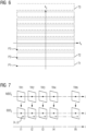
- FIG. 2 A roughly schematic example of an applicable pulse sequence is in Figure 2 represented using a pulse sequence diagram.
- an excitation pulse RF-A i After an excitation pulse RF-A i , after an echo time TE i , an echo signal ES i , each shown in the top line (RF) representing the high-frequency activity, is read out (ADC) in a readout period R i .
- ADC read out
- additional RF pulses can also be switched between the excitation pulse RF-A i and the echo signal ES i , which have not been shown for the sake of clarity.
- a gradient train GT i which can include gradients in all gradient directions G, is switched, the exact design of which in turn depends on the type of pulse sequence selected and the k-space trajectory T i , and is fundamentally known to the person skilled in the art. Therefore, the gradient train GT i is only indicated by a box.
- TR i which can vary according to the invention
- the pulse sequence diagram is repeated, as indicated by the following excitation pulse RF-A i+1 , with different gradients in the gradient train GT i being switched in each repetition i and/or other RF pulses can be irradiated.
- a flip angle of irradiated RF pulses in particular of the excitation pulse RF-A i , can be varied in each repetition time TR i .
- a query 105 asks whether all N desired repetitions have already been carried out and the corresponding N measurement data sets MSDi have been saved. If this is not the case ("n", query 105), a k-space trajectory that is optimal for the next repetition is selected and the parameters of the pulse sequence are adjusted accordingly and, if necessary, additionally varied (block 107). As a rule, a selected further k-space trajectory T i+1 will differ from a previous k-space trajectory T i .
- the pulse sequence is repeated and thus a new measurement (block 103) is carried out, such that that measurement data is measured in successive repetitions along the optimally selected k-space trajectories T i , T i+1 .
- the further k-space trajectory T i+1 is determined here, for example, by applying a rotation and/or a translation to the first k-space trajectory T1 or by shortening another k-space trajectory.
- Geometric operations such as reflections or enlargements or reductions, can be used to determine further k-space trajectories from already selected k-space trajectories.
- corrections for example with regard to eddy currents and/or delays, are applied, which can be different, for example, in the kx, ky and kz directions, and which influence the respective k-space trajectory.
- a further k-space trajectory can also be constructed as a section of another k-space trajectory to be used, which can optionally still be rotated and/or shifted.
- the rotations and/or translations used and, if applicable, sections to which a further k-space trajectory is shortened in comparison to another are chosen in such a way that the k-space is in a desired manner through all k-space used trajectories are covered.
- a set of k-space trajectories T i to be used can also be defined first, which are to be used for the repetitions and which, for example, cover the k-space as a whole in a desired manner, for example by a desired over-or To achieve under-sampling or a sampling distribution in the relevant k-space.
- k-space trajectories that cannot be derived from one another through geometric operations can also be selected.
- the desired sampling distribution can be determined in particular with regard to a desired use of the generated pixel-time series.
- the set of k-space trajectories T i to be used therefore also determines a number n of different k-space trajectories T i to be used in total.
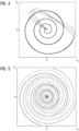
- FIG. 3 An example of a possible distribution of k-space trajectories is in Figure 3 shown.
- n k-space trajectories
- the distribution of the radial sampling rate "A" applicable here according to Nyquist is plotted on the right over increasing values in k-space.
- each of the n 48
- a number of different k-space trajectories to be used in total and/or a degree of undersampling of a measurement data set can be taken into account.
- a scanning that is as homogeneous as possible may be desired, at least in certain k-space regions, for example in a central region and/or in a peripheral region.
- a sampling that becomes more dense towards the k-space center may also be desired.
- a homogeneous distribution of the sampling for example, in the case of a Cartesian k-space trajectory, a maximum translation between two k-space trajectories to be used can be determined and this maximum translation can be divided into equidistant translation steps according to a desired sampling density in order to achieve one outermost k-space trajectory is shifted to obtain another k-space trajectory to be used.
- the length of the equidistant translation steps can be determined as the quotient of the maximum translation divided by the number N of repetitions to be carried out or divided by a (even non-integer) number smaller than N.
- a maximum rotation 360°
- a set of k-space trajectories to be used at least once in the course of the repetitions can be determined, which can be taken into account when selecting the k-space trajectories along which measurement data is to be measured in successive repetitions.
- the further k-space trajectories are then determined by a stepwise rotation according to a desired rotation step size and/or by a stepwise translation according to a desired translation step size.
- k-space trajectories along which measurement data are to be measured in successive repetitions can be randomly selected.
- k-space trajectories along which measurement data are to be measured in successive repetitions can be selected in a non-chronological order. In this way, artifacts caused by not fully compensated gradient moments or accidental measurement of signals from a previous repetition can be avoided or at least minimized.
- k-space trajectories along which measurement data are to be measured in successive repetitions can be selected in such a way that measurement data along k-space trajectories in successive repetitions , which have alternating gradients, are measured. In this way, disruptive eddy currents are avoided.
- the choice of the k-space trajectories to be measured one after the other can be optimized according to at least one of the following criteria: a reduction of artifacts in the reconstructed image data sets, a reduction of a spatial and/or temporal shift of intensity values in the reconstructed image data sets.
- results of, for example, successive k-space trajectories selected according to various of the criteria already mentioned above can be compared.
- further optimization criteria can also include, for example, the best possible reduction of spatial erroneous deviations in the parameter maps obtained as a result and/or the greatest possible homogeneity of those displayed in the parameter maps obtained as a result Parameter values can be in areas of the same tissue.
- homogeneity can be controlled, for example, via reference measurements or through measurements on phantoms that are homogeneous at least in some areas.
- further optimization criteria can include, for example, a distribution of the k-space trajectories that is as random as possible in order to achieve a so-called as insensitive as possible To be able to determine the baseline from the pixel-time series or, if possible, not to use the same k-space trajectories or even to use k-space trajectories that are as orthogonal as possible during different applications of the paradigm at the same time in the paradigm when the same paradigm is used multiple times to achieve an averaging effect.
- FIG 5 an example of a choice according to the invention of four k-space trajectories to be used in successive repetitions by rotating certain ones is shown.
- the different k-space trajectories are shown in different dashed lines to make differentiation easier.
- the k-space trajectories shown according to the invention cover the k-space more broadly than those in Figure 3 shown.
- k-space trajectories shown were randomly selected from the 48 k-space trajectories presented in Figure 3 are shown, selected.
- Figure 6 shows an example of a selection of further k-space trajectories determined by translation.
- the k-space trajectories shown here correspond to a Cartesian scanning of k-space, for example according to an EPI pulse sequence.
- the first k-space trajectory T1 starts at the starting point P1.
- the second k-space trajectory T2, which is to be used in the following repetition, is shifted in the positive ky direction by a translation step of 5 times the smallest translation step size between two k-space trajectories to be used in all repetitions.
- the third k-space trajectory T3, which is to be used in the third repetition, is in turn in the positive ky direction by a translation step of 5 times the smallest translation step size between two k-space trajectories to be used in all repetitions compared to the previous one k-space trajectory T2 shifted.
- K-space trajectories T1 and T2 or T2 and T3 to be used consecutively are therefore not shifted chronologically in accordance with the smallest translation step size between two k-space trajectories to be used in all repetitions, but with a step size increased by a factor of 5.
- Such a multiple step scheme can be carried out with a wide variety of multiples (not equal to one), including non-integer ones.
- the choice of the multiple can, for example, influence how uniform the k-space is is sampled in successive repetitions.
- the k-space is only covered in a small area in a few repetitions (see e.g. similar to in Figure 3 ), at larger multiples, a larger area of the relevant k-space is sampled with just a few repetitions.
- the k-space trajectories along which measurement data are measured in successive repetitions can be selected such that a k-space trajectory is created by a translation of an immediately preceding k-space trajectory by a multiple V of the smallest translation step size between two im Framework of all repetitions k-space trajectories to be used is determined if the further k-space trajectories are determined by translation of the first k-space trajectory.
- the k-space trajectories along which measurement data are measured in successive repetitions can also be selected in such a way that a k-space trajectory is created by rotating an immediately preceding k-space trajectory by a multiple of the smallest rotation step size between two im
- the k-space trajectories to be used within the framework of all repetitions are determined if the further k-space trajectories are determined by rotation of the first k-space trajectory.
- the image data sets BDS i reconstructed from the measurement data sets MDS i are shown in the same way, with an example of an image point (x,y) being marked in the image data sets BDS i .
- the respective intensity of the pixel (x,y) at the times T i corresponding to the repetitions T i can be plotted against time, ie against the number i of the repetition as a pixel-time series .
- the stored pixel-time series (x,y)(i) can further be compared with a comparison data set VDS(i) and information about the examination object can be obtained from the comparison as a result (block 113).
- MRF methods and fMRI methods come into consideration here, whereby the comparison data set corresponds to a signal curve from a magnetic resonance fingerprinting database, with the result being, for example, a quantitative T1 map and/or a quantitative T2 map and/or a quantitative proton density map can be obtained, or a paradigm of a functional magnetic resonance procedure, whereby information about active brain areas can be obtained as a result.
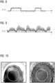
- Figure 8 shows the course of the intensities of an image point (x,y) over time, shown with a thinner line, compared to an fMRI paradigm shown with a bolder line as a comparison data set in which certain stimuli acted on the examination object.
- Figure 9 an intensity curve of an image point (x,y) over time is shown with a thinner line compared to the fitted signal curve from the MRF database shown with a thicker line as a comparison data set.
- the respective comparison data sets are well within the average of the fluctuations. This shows that spatial and (especially in the case of use in fMRI) temporal shifts of intensity values in the reconstructed image data sets were avoided by creating the pixel-time series according to the invention.
- Figure 10 compares a parameter map (left) that is not determined based on pixel-time series generated according to the invention with a corresponding parameter map (right) that is determined based on pixel-time series generated according to the invention.
- the parameter map shown on the left shading artifacts can be clearly seen, whereas such artifacts cannot be seen in the parameter map shown on the right from pixel-time series created using the method according to the invention, otherwise determined in the same way are.
- the use of the pixel-time series generated according to the invention for determining the parameter map has thus led to a reduction, if not complete avoidance, of undesirable artifacts.
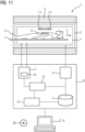
- Figure 11 schematically represents a magnetic resonance system 1 according to the invention.
- This includes a magnet unit 3 for generating the basic magnetic field, a gradient unit 5 for generating the gradient fields, a high-frequency unit 7 for irradiating and receiving high-frequency signals and a control device 9 designed to carry out a method according to the invention.
- the high-frequency unit 7 can consist of several subunits, for example of several coils such as the schematically shown coils 7.1 and 7.2 or more coils, which can be designed either only for sending high-frequency signals or only for receiving the triggered high-frequency signals or for both.
- the layer S represents an exemplary target volume of the examination object from which measurement data can be recorded.
- the control device 9 is used to control the magnetic resonance system and can in particular control the gradient unit 5 by means of a gradient control 5 'and the high-frequency unit 7 by means of a high-frequency transmit/receive control 7'.
- the high-frequency unit 7 can include several channels on which signals can be sent or received.
- the high-frequency unit 7, together with its high-frequency transmit/receive control 7', is used for generating and radiating (sending) a high-frequency alternating field for manipulating the spins in a region to be manipulated (for example in slices S to be measured) of the examination object U responsible.
- the center frequency of the high-frequency alternating field also known as the B1 field, must be close to the resonance frequency of the spins to be manipulated.
- controlled currents are applied to the HF coils in the high-frequency unit 7 by means of the high-frequency transmit/receive controller 7'.
- a measurement data distribution unit 7a according to the invention which can be included, for example, in the high-frequency transmit/receive controller 7' can, determines which measurement data is recorded according to the invention and assigned to which data set.
- control device 9 includes an optimization unit 15, with which k-space trajectories can be selected in an optimized manner according to the invention.
- the control device 9 is designed overall to carry out a method according to the invention to avoid artifacts when acquiring MR data of an examination object.
- a computing unit 13 included in the control device 9 is designed to carry out all the computing operations required for the necessary measurements and determinations. Intermediate results and results required for this or determined here can be stored in a storage unit S of the control device 9.
- the units shown are not necessarily to be understood as physically separate units, but merely represent a subdivision into meaningful units, which can also be realized, for example, in fewer or in just a single physical unit.
- control commands can be sent to the magnetic resonance system, for example by a user, and/or results of the control device 9, such as image data, can be displayed.
- a method described herein may also be in the form of a computer program product which comprises a program and implements the method described on a control device 9 when it is executed on the control device 9.
- an electronically readable data carrier 26 can be present with electronically readable control information stored thereon, which includes at least one such computer program product just described and is designed in such a way that when the data carrier 26 is used in a control device 9 of a magnetic resonance system 1, they carry out the method described.
Landscapes
- Physics & Mathematics (AREA)
- General Physics & Mathematics (AREA)
- High Energy & Nuclear Physics (AREA)
- Condensed Matter Physics & Semiconductors (AREA)
- Engineering & Computer Science (AREA)
- Signal Processing (AREA)
- Nuclear Medicine, Radiotherapy & Molecular Imaging (AREA)
- Health & Medical Sciences (AREA)
- General Health & Medical Sciences (AREA)
- Radiology & Medical Imaging (AREA)
- Theoretical Computer Science (AREA)
- Artificial Intelligence (AREA)
- Computer Vision & Pattern Recognition (AREA)
- Magnetic Resonance Imaging Apparatus (AREA)
Claims (10)
- Procédé de production d'une série ((x, y)(i)) de points image - temps d'un objet (U) à examiner, au moyen d'une technique de résonnance magnétique, comprenant les stades :- dans une première répétition, arrivée d'impulsions RF (RF-Ai, RF-Ai+1), commutation de gradients (GTi) et lecture (Ri) de signaux (ESi) d'écho produits par les impulsions RF (RF-Ai, RF-Ai+1) arrivées et les gradients (GTi) commutés suivant une séquence d'impulsions, de manière à enregistrer, le long d'une première trajectoire (Ti) dans l'espace k, des données de mesure après une excitation par une impulsion d'excitation RF (RF-Ai) et à les mettre en mémoire en un ensemble (MDSi) de données de mesure, dans lequel l'ensemble (MDSi) de données de mesure est sous-échantillonné suivant Nyquist,- répétition plusieurs fois de la séquence d'impulsions avec commutation de respectivement d'autres gradients (GTi) et éventuellement avec arrivée respectivement d'autres impulsions RF (RF-Ai+1), de manière à ce que,
à chaque répétition, après la une impulsion d'excitation RF (RF-Ai+1), on mesure des données de mesure, le long d'une autre trajectoire (Ti+1) dans l'espace k et on les met en mémoire en des ensembles (MDSi) respectifs de données de mesure,- reconstruction d'un ensemble (BDSi) de données d'image par ensemble (MDSi) de données de mesure,- formation d'au moins une série ((x, y)(i)) de points image - temps pour au moins un point image ((x, y)), à partir des ensembles (BDSi) de données d'image reconstruits, qui représentent une intensité de signal du point image ((x, y)) au cours des temps d'enregistrement des ensembles (MDSi) de données de mesure,- mise en mémoire de la au moins une série ((x, y)(i)) de points image - temps formée, caractérisé en ce que l'on effectue les répétitions, de manière à ce que, dans des répétitions successives, des données d'image soient mesurées de long de trajectoires (Ti+1) dans l'espace k sélectionnées de manière optimisée, dans lequel, pour l'optimisation, on compare des résultats de trajectoires dans l'espace k successives choisies suivant des critères différents,dans lequel le choix des trajectoires (Ti, Ti+1) dans l'espace k, à mesurer les unes après les autres est optimisé suivant au moins l'un des critères suivants : une réduction d'artefacts dans les ensembles de données d'image reconstruits, une réduction d'un décalage dans l'espace et/ou dans le temps de valeurs d'intensité dans les ensembles de données d'image reconstruits, et dans lequel les autres trajectoires (Ti+1) dans l'espace k sont déterminées par une rotation pas à pas, suivant une largeur de pas de rotation, et/ou par une translation pas à pas, suivant une largeur de pas de translation, etdans lequel on choisit les trajectoires (Ti, Ti+1) dans l'espace k le long desquelles on mesure des données de mesure en des répétitions successives, de manière à ce qu'une trajectoire (Ti+1) dans l'espace k soit déterminée par une rotation d'une trajectoire (Ti) dans l'espace k immédiatement précédente d'un multiple d'une largeur de pas de rotation la plus petite entre deux trajectoires dans l'espace k à utiliser dans le cadre de toutes les répétitions, si les autres trajectoires dans l'espace k sont déterminées par rotation de la première trajectoire dans l'espace k, et/ou de manière à ce qu'une trajectoire (Ti+1) dans l'espace k soit déterminée par une translation d'une trajectoire (Ti) dans l'espace k immédiatement précédente d'un multiple d'une largeur de pas de translation la plus petite entre deux trajectoires dans l'espace k, à utiliser dans le cadre de toutes les répétitions, si les autres trajectoires dans l'espace k sont déterminées par translation de la première trajectoire dans l'espace k. - Procédé suivant la revendication 1, dans lequel chaque trajectoire (Ti+1) dans l'espace k est déterminée par application d'une rotation et/ou d'une translation à la première trajectoire (Ti) dans l'espace k et/ou par utilisation d'une autre opération géométrique sur une autre trajectoire dans l'espace k.
- Procédé suivant l'une des revendications précédentes, dans lequel les trajectoires (Ti, Ti+1) dans l'espace k, le long desquelles on mesure des données de mesure dans une répétition, balayent cartésiennement, en forme de spirale ou radialement l'espace k.
- Procédé suivant l'une des revendications précédentes, dans lequel on compare des séries ((x,y)(i)) de points image - temps mises en mémoire à un ensemble (VDS(i)) de données de comparaison et, à partir de la comparaison, on obtient des informations sur l'objet (U) à examiner.
- Procédé suivant la revendication 4, dans lequel l'ensemble (VDS(i)) de données de comparaison est une courbe de signal d'empreinte digitale de résonnance magnétique ou un paradigme d'un procédé fonctionnel par résonnance magnétique.
- Procédé suivant l'une des revendications précédentes, dans lequel le choix des trajectoires (Ti, Ti+1) dans l'espace k, le long desquelles on doit mesurer des données de mesure en des répétitions successives, prend en compte un nombre (n) de diverses trajectoires dans l'espace à appliquer dans l'ensemble et/ou un degré du sous-échantillonnage d'un ensemble (MDSi) de données de mesure enregistré.
- Procédé suivant l'une des revendications précédentes, dans lequel le choix des trajectoires (Ti, Ti+1) dans l'espace k, le long desquelles on mesure des données de mesure en des répétitions successives, prend en compte un ensemble de trajectoires dans l'espace k différentes, le long desquelles on doit mesurer au moins une fois des données de mesure et on choisit les trajectoires (Ti, Ti+1) dans l'espace k, de manière à mesurer, dans des répétitions successives, des données de mesure, le long de trajectoires dans l'espace k choisies aléatoirement dans l'ensemble de trajectoires dans l'espace k différentes et/ou on choisit les trajectoires dans l'espace k, de manière à ce que, dans des répétitions successives, on mesure des données de mesure, le long de trajectoires de l'espace k, qui ont des gradients en alternance.
- Installation (1) de résonnance magnétique, comprenant une unité (3) d'aimant, une unité (5) de gradient, une unité (7) de haute fréquence et un dispositif (9) de commande ayant une commande (7') d'émission / réception de haute fréquence, caractérisée en ce que le dispositif (9) de commande comprend une unité (15) d'optimisation, par laquelle on peut choisir, de manière optimisée, des trajectoires dans l'espace k et qui est constituée pour effectuer un procédé suivant l'une des revendications 1 à 7 sur l'installation (1) de résonnance magnétique.
- Produit de programme d'ordinateur, qui comprend un programme d'ordinateur et qui peut être chargé directement dans une mémoire d'un dispositif (9) de commande d'une installation (1) de résonnance magnétique, caractérisé en ce que le programme d'ordinateur comprend des moyens de programme pour effectuer les stades du procédé suivant l'une des revendications 1 à 7, lorsque le programme d'ordinateur est réalisé dans le dispositif (9) de commande de l'installation (1) de résonnance magnétique.
- Support de données, déchiffrable électroniquement, sur lequel sont mises en mémoire des informations de commande pouvant être déchiffrées électroniquement, caractérisé en ce que les informations de commande, pouvant être déchiffrées électroniquement, mises en mémoire sur le support de données pouvant être déchiffré électroniquement, comprennent au moins un programme d'ordinateur tel que défini à la revendication 9, et sont conformées de manière à ce qu'elles effectuent, lors de l'utilisation du support de données dans un dispositif (9) de commande d'une installation (1) de résonnance magnétique, un procédé suivant l'une des revendications 1 à 7.
Applications Claiming Priority (1)
| Application Number | Priority Date | Filing Date | Title |
|---|---|---|---|
| DE102016217675.7A DE102016217675A1 (de) | 2016-09-15 | 2016-09-15 | Verbesserte Erzeugung von Bildpunkt-Zeit-Serien eines Untersuchungsobjektes mittels Magnetresonanztechnik |
Publications (3)
| Publication Number | Publication Date |
|---|---|
| EP3299833A1 EP3299833A1 (fr) | 2018-03-28 |
| EP3299833C0 EP3299833C0 (fr) | 2023-10-25 |
| EP3299833B1 true EP3299833B1 (fr) | 2023-10-25 |
Family
ID=58501382
Family Applications (2)
| Application Number | Title | Priority Date | Filing Date |
|---|---|---|---|
| EP17165569.9A Active EP3296757B1 (fr) | 2016-09-15 | 2017-04-07 | Mesure d'empreinte digitale par résonance magnétique sans artéfact |
| EP17185874.9A Active EP3299833B1 (fr) | 2016-09-15 | 2017-08-11 | Génération améliorée des séries chronologiques de points image d'un objet examiné au moyen de la technique de résonance magnétique |
Family Applications Before (1)
| Application Number | Title | Priority Date | Filing Date |
|---|---|---|---|
| EP17165569.9A Active EP3296757B1 (fr) | 2016-09-15 | 2017-04-07 | Mesure d'empreinte digitale par résonance magnétique sans artéfact |
Country Status (3)
| Country | Link |
|---|---|
| US (2) | US10663545B2 (fr) |
| EP (2) | EP3296757B1 (fr) |
| DE (1) | DE102016217675A1 (fr) |
Families Citing this family (15)
| Publication number | Priority date | Publication date | Assignee | Title |
|---|---|---|---|---|
| DE102016204145A1 (de) * | 2016-03-14 | 2017-09-14 | Siemens Healthcare Gmbh | Verfahren zur Aufnahme eines Magnetresonanzdatensatzes, Magnetresonanzeinrichtung, Computerprogramm und elektronisch lesbarer Datenträger |
| DE102016217675A1 (de) | 2016-09-15 | 2018-03-15 | Siemens Healthcare Gmbh | Verbesserte Erzeugung von Bildpunkt-Zeit-Serien eines Untersuchungsobjektes mittels Magnetresonanztechnik |
| US10459055B2 (en) * | 2017-04-07 | 2019-10-29 | Case Western Reserve University | System and method for reduced field of view MR fingerprinting for parametric mapping |
| DE102018209584A1 (de) * | 2018-06-14 | 2019-12-19 | Siemens Healthcare Gmbh | Magnetresonanz-Fingerprinting-Verfahren |
| EP3588121B1 (fr) * | 2018-06-21 | 2022-09-14 | Siemens Healthcare GmbH | Procédé de filigranage par résonance magnétique |
| US10996300B2 (en) * | 2018-09-05 | 2021-05-04 | Siemens Healthcare Gmbh | Cartesian-radial hybrid k-space trajectory for volumetric imaging |
| EP3629048A1 (fr) | 2018-09-27 | 2020-04-01 | Siemens Healthcare GmbH | Prise d'empreintes à résonance magnétique à champs faible |
| EP3644086A1 (fr) | 2018-10-25 | 2020-04-29 | Bayer AG | Procédé de prise d'empreintes à résonance magnétique pour des acquisitions avec un agent de contraste |
| DE102019206827A1 (de) | 2019-05-10 | 2020-11-12 | Siemens Healthcare Gmbh | Magnetresonanz-Fingerprinting-Verfahren |
| EP3770625B1 (fr) * | 2019-07-24 | 2024-06-26 | Siemens Healthineers AG | Irm utilisant uen détection comprimée avec amélioration des paramètres de régularisation |
| EP3882850A1 (fr) * | 2020-03-20 | 2021-09-22 | Siemens Healthcare GmbH | Procédé et système pour mesurer une étape de maturation à l'aide d'irm |
| US11875509B2 (en) * | 2020-04-03 | 2024-01-16 | Case Western Reserve University | System and method for determining undersampling errors for a magnetic resonance fingerprinting pulse sequence |
| DE102020209382A1 (de) * | 2020-07-24 | 2022-01-27 | Siemens Healthcare Gmbh | Verfahren zur Aufnahme von Messdaten mittels einer Magnetresonanzanlage mit einer Korrektur der verwendeten k-Raumtrajektorien |
| EP4152031A1 (fr) * | 2021-09-17 | 2023-03-22 | Siemens Healthcare GmbH | Procédé de détermination d'un ensemble de données fonctionnelles de résonance magnétique, dispositif d'imagerie par résonance magnétique, programme informatique et support d'informations lisible électroniquement |
| CN114159027B (zh) * | 2021-11-26 | 2024-04-12 | 浙江大学 | 一种变回波个数的磁共振指纹成像方法 |
Citations (1)
| Publication number | Priority date | Publication date | Assignee | Title |
|---|---|---|---|---|
| WO2015073894A2 (fr) * | 2013-11-15 | 2015-05-21 | New York University | Émission parallèle à auto-étalonnage par empreinte numérique unique dynamique à rotation |
Family Cites Families (10)
| Publication number | Priority date | Publication date | Assignee | Title |
|---|---|---|---|---|
| DE102013201814B4 (de) | 2013-02-05 | 2018-11-08 | Siemens Healthcare Gmbh | Verfahren zur Magnetresonanz-Bildgebung mit multidimensional ortsselektiven HF-Pulsen in einem Außenbereich |
| US20170003365A1 (en) | 2014-03-14 | 2017-01-05 | The General Hospital Corporation | System and method for magnetic resonance fingerprinting |
| US10422845B2 (en) | 2014-10-24 | 2019-09-24 | The General Hospital Corporation | Systems and methods for steady-state magnetic resonance fingerprinting |
| DE102014224662B4 (de) | 2014-12-02 | 2016-07-07 | Siemens Healthcare Gmbh | Verbesserung einer MR-Fingerprinting-Messung |
| US10598750B2 (en) * | 2015-04-02 | 2020-03-24 | The General Hospital Corporation | 3D balanced EPI magnetic resonance fingerprinting |
| US10466321B2 (en) * | 2015-11-12 | 2019-11-05 | The General Hospital Corporation | Systems and methods for efficient trajectory optimization in magnetic resonance fingerprinting |
| US10180476B2 (en) * | 2015-11-25 | 2019-01-15 | The General Hospital Corporation | Systems and methods for segmented magnetic resonance fingerprinting dictionary matching |
| US10816625B2 (en) * | 2016-04-26 | 2020-10-27 | Koninklijke Philips N.V. | Silent 3D magnetic resonance fingerprinting |
| DE102016217675A1 (de) | 2016-09-15 | 2018-03-15 | Siemens Healthcare Gmbh | Verbesserte Erzeugung von Bildpunkt-Zeit-Serien eines Untersuchungsobjektes mittels Magnetresonanztechnik |
| EP3457159A1 (fr) * | 2017-09-19 | 2019-03-20 | Siemens Healthcare GmbH | Procédé de prise d'empreintes par résonance magnétique amélioré |
-
2016
- 2016-09-15 DE DE102016217675.7A patent/DE102016217675A1/de active Pending
-
2017
- 2017-04-07 EP EP17165569.9A patent/EP3296757B1/fr active Active
- 2017-08-11 EP EP17185874.9A patent/EP3299833B1/fr active Active
- 2017-09-08 US US15/699,935 patent/US10663545B2/en active Active
- 2017-09-08 US US15/699,685 patent/US10429470B2/en active Active
Patent Citations (1)
| Publication number | Priority date | Publication date | Assignee | Title |
|---|---|---|---|---|
| WO2015073894A2 (fr) * | 2013-11-15 | 2015-05-21 | New York University | Émission parallèle à auto-étalonnage par empreinte numérique unique dynamique à rotation |
Non-Patent Citations (4)
| Title |
|---|
| DAN MA ET AL: "Music-based magnetic resonance fingerprinting to improve patient comfort during MRI examinations : MRF-Music", MAGNETIC RESONANCE IN MEDICINE, vol. 75, no. 6, 16 July 2015 (2015-07-16), pages 2303 - 2314, XP055532819, ISSN: 0740-3194, DOI: 10.1002/mrm.25818 * |
| INTERNATIONAL SOCIETY FOR MAGNETIC RESONANCE IN MEDICINE, ISMRM, 2030 ADDISON STREET, 7TH FLOOR, BERKELEY, CA 94704 USA, no. 4214, 15 May 2015 (2015-05-15), XP040669890 * |
| JANG JINSEONG ET AL: "Medical image matching using variable randomized undersampling probability pattern in data acquisition", 2014 INTERNATIONAL CONFERENCE ON ELECTRONICS, INFORMATION AND COMMUNICATIONS (ICEIC), IEEE, 15 January 2014 (2014-01-15), pages 1 - 2, XP032653103, DOI: 10.1109/ELINFOCOM.2014.6914453 * |
| MAZOR GAL ET AL: "Low rank magnetic resonance fingerprinting", 2016 38TH ANNUAL INTERNATIONAL CONFERENCE OF THE IEEE ENGINEERING IN MEDICINE AND BIOLOGY SOCIETY (EMBC), IEEE, 16 August 2016 (2016-08-16), pages 439 - 442, XP032979186, DOI: 10.1109/EMBC.2016.7590734 * |
Also Published As
| Publication number | Publication date |
|---|---|
| US20180074145A1 (en) | 2018-03-15 |
| EP3299833A1 (fr) | 2018-03-28 |
| EP3296757A1 (fr) | 2018-03-21 |
| EP3296757B1 (fr) | 2024-09-04 |
| DE102016217675A1 (de) | 2018-03-15 |
| EP3299833C0 (fr) | 2023-10-25 |
| US10663545B2 (en) | 2020-05-26 |
| US10429470B2 (en) | 2019-10-01 |
| US20180074148A1 (en) | 2018-03-15 |
Similar Documents
| Publication | Publication Date | Title |
|---|---|---|
| EP3299833B1 (fr) | Génération améliorée des séries chronologiques de points image d'un objet examiné au moyen de la technique de résonance magnétique | |
| EP3413072A1 (fr) | Procédé de multiplexage de couche en irm | |
| DE102014206395B4 (de) | Aufnahme und iterative Rekonstruktion einer Parameterkarte eines Zielbereichs | |
| DE102013205785A1 (de) | Ermittlung einer Magnetresonanzsystem-Ansteuersequenz auf Basis einer reduzierten Anzahl an Feldverteilungskarten | |
| DE102018218471B3 (de) | Verfahren zur Magnetresonanzbildgebung mit Zusatzgradientenpulsen, Magnetresonanzeinrichtung, Computerprogramm und elektronisch lesbarer Datenträger | |
| DE102018113437A1 (de) | Mr-tomografie unter verwendung einer stack-of-stars-erfassung mit variablem kontrast | |
| DE102013108467A1 (de) | Segment-Akquisition mit mehrfacher Anregung zur Bewegungskorrektur in der Magnetresonanztomographie | |
| DE102011083619A1 (de) | Verfahren zur Erzeugung einer Serie von MR-Bildern zur Überwachung einer Position eines in einem Untersuchungsgebiet befindlichen Interventionsgeräts, Magnetresonanzanlage, Computerprogrammprodukt und elektronisch lesbarer Datenträger | |
| DE102019206827A1 (de) | Magnetresonanz-Fingerprinting-Verfahren | |
| EP3460501B1 (fr) | Procédé rm de multiplexage de couche | |
| DE10338075A1 (de) | Verfahren zur ortsaufgelösten Messung der B1-Feldverteilung bei MR-Messungen | |
| DE102018209584A1 (de) | Magnetresonanz-Fingerprinting-Verfahren | |
| DE102020212173A1 (de) | Verfahren zur Erfassung von Referenzdaten für eine Phasenkorrektur in der Magnetresonanztechnik | |
| EP3457159A1 (fr) | Procédé de prise d'empreintes par résonance magnétique amélioré | |
| EP3828576B1 (fr) | Procédé de génération d'au moins un ensemble de données d'image et d'un ensemble de données d'image de référence, support de données, produit programme informatique ainsi qu'installation de résonance magnétique | |
| DE102020212250A1 (de) | Ermittlung einer PSF für eine Rekonstruktion von Bilddaten aus mittels einer Magnetresonanzanlage aufgenommenen Messdaten | |
| DE102010041659B4 (de) | Erzeugung eines optimierten MR-Bildes eines Untersuchungsobjekts durch Einstrahlen einer mindestens zwei HF-Pulse umfassenden Pulsfolge | |
| DE112019005169T5 (de) | Magnetresonanztomographie mit bewegungskompensierter bildrekonstruktion | |
| DE102019201385B3 (de) | Verfahren zur Aufnahme von Magnetresonanzdaten, Magnetresonanzeinrichtung, Computerprogramm und elektronisch lesbarer Datenträger | |
| EP3798658B1 (fr) | Enregistrement amélioré multicouche simultané (sms) des données de mesure au moyen de la technique du résonance magnétique | |
| EP3828581B1 (fr) | Procédé de génération d'au moins un ensemble de données d'image et d'un ensemble de données d'image de référence, produit programme informatique ainsi qu'installation de résonance magnétique | |
| EP3629048A1 (fr) | Prise d'empreintes à résonance magnétique à champs faible | |
| DE102016218557B4 (de) | Verkürzung der Wiederholzeit ohne Erhöhung der Gradientenauslastung in der Magnetresonanztechnik | |
| EP3629047A1 (fr) | Procédé de prise d'empreintes à résonance magnétique basé sur des valeurs de similarité | |
| DE102018220348A1 (de) | Bewegungsstabiles Schicht-Multiplexing-Verfahren |
Legal Events
| Date | Code | Title | Description |
|---|---|---|---|
| PUAI | Public reference made under article 153(3) epc to a published international application that has entered the european phase |
Free format text: ORIGINAL CODE: 0009012 |
|
| STAA | Information on the status of an ep patent application or granted ep patent |
Free format text: STATUS: THE APPLICATION HAS BEEN PUBLISHED |
|
| AK | Designated contracting states |
Kind code of ref document: A1 Designated state(s): AL AT BE BG CH CY CZ DE DK EE ES FI FR GB GR HR HU IE IS IT LI LT LU LV MC MK MT NL NO PL PT RO RS SE SI SK SM TR |
|
| AX | Request for extension of the european patent |
Extension state: BA ME |
|
| STAA | Information on the status of an ep patent application or granted ep patent |
Free format text: STATUS: REQUEST FOR EXAMINATION WAS MADE |
|
| 17P | Request for examination filed |
Effective date: 20180925 |
|
| RBV | Designated contracting states (corrected) |
Designated state(s): AL AT BE BG CH CY CZ DE DK EE ES FI FR GB GR HR HU IE IS IT LI LT LU LV MC MK MT NL NO PL PT RO RS SE SI SK SM TR |
|
| STAA | Information on the status of an ep patent application or granted ep patent |
Free format text: STATUS: EXAMINATION IS IN PROGRESS |
|
| STAA | Information on the status of an ep patent application or granted ep patent |
Free format text: STATUS: EXAMINATION IS IN PROGRESS |
|
| 17Q | First examination report despatched |
Effective date: 20210824 |
|
| GRAP | Despatch of communication of intention to grant a patent |
Free format text: ORIGINAL CODE: EPIDOSNIGR1 |
|
| STAA | Information on the status of an ep patent application or granted ep patent |
Free format text: STATUS: GRANT OF PATENT IS INTENDED |
|
| INTG | Intention to grant announced |
Effective date: 20230623 |
|
| GRAS | Grant fee paid |
Free format text: ORIGINAL CODE: EPIDOSNIGR3 |
|
| GRAA | (expected) grant |
Free format text: ORIGINAL CODE: 0009210 |
|
| STAA | Information on the status of an ep patent application or granted ep patent |
Free format text: STATUS: THE PATENT HAS BEEN GRANTED |
|
| AK | Designated contracting states |
Kind code of ref document: B1 Designated state(s): AL AT BE BG CH CY CZ DE DK EE ES FI FR GB GR HR HU IE IS IT LI LT LU LV MC MK MT NL NO PL PT RO RS SE SI SK SM TR |
|
| REG | Reference to a national code |
Ref country code: GB Ref legal event code: FG4D Free format text: NOT ENGLISH |
|
| REG | Reference to a national code |
Ref country code: CH Ref legal event code: EP |
|
| REG | Reference to a national code |
Ref country code: DE Ref legal event code: R096 Ref document number: 502017015522 Country of ref document: DE |
|
| REG | Reference to a national code |
Ref country code: IE Ref legal event code: FG4D Free format text: LANGUAGE OF EP DOCUMENT: GERMAN |
|
| U01 | Request for unitary effect filed |
Effective date: 20231026 |
|
| U07 | Unitary effect registered |
Designated state(s): AT BE BG DE DK EE FI FR IT LT LU LV MT NL PT SE SI Effective date: 20231102 |
|
| U1N | Appointed representative for the unitary patent procedure changed [after the registration of the unitary effect] |
Representative=s name: SIEMENS HEALTHINEERS PATENT ATTORNEYS; DE |
|
| RAP2 | Party data changed (patent owner data changed or rights of a patent transferred) |
Owner name: SIEMENS HEALTHINEERS AG |
|
| U1K | Transfer of rights of the unitary patent after the registration of the unitary effect |
Owner name: SIEMENS HEALTHINEERS AG; DE |
|
| PG25 | Lapsed in a contracting state [announced via postgrant information from national office to epo] |
Ref country code: GR Free format text: LAPSE BECAUSE OF FAILURE TO SUBMIT A TRANSLATION OF THE DESCRIPTION OR TO PAY THE FEE WITHIN THE PRESCRIBED TIME-LIMIT Effective date: 20240126 |
|
| PG25 | Lapsed in a contracting state [announced via postgrant information from national office to epo] |
Ref country code: IS Free format text: LAPSE BECAUSE OF FAILURE TO SUBMIT A TRANSLATION OF THE DESCRIPTION OR TO PAY THE FEE WITHIN THE PRESCRIBED TIME-LIMIT Effective date: 20240225 |
|
| PG25 | Lapsed in a contracting state [announced via postgrant information from national office to epo] |
Ref country code: ES Free format text: LAPSE BECAUSE OF FAILURE TO SUBMIT A TRANSLATION OF THE DESCRIPTION OR TO PAY THE FEE WITHIN THE PRESCRIBED TIME-LIMIT Effective date: 20231025 |
|
| PG25 | Lapsed in a contracting state [announced via postgrant information from national office to epo] |
Ref country code: IS Free format text: LAPSE BECAUSE OF FAILURE TO SUBMIT A TRANSLATION OF THE DESCRIPTION OR TO PAY THE FEE WITHIN THE PRESCRIBED TIME-LIMIT Effective date: 20240225 Ref country code: GR Free format text: LAPSE BECAUSE OF FAILURE TO SUBMIT A TRANSLATION OF THE DESCRIPTION OR TO PAY THE FEE WITHIN THE PRESCRIBED TIME-LIMIT Effective date: 20240126 Ref country code: ES Free format text: LAPSE BECAUSE OF FAILURE TO SUBMIT A TRANSLATION OF THE DESCRIPTION OR TO PAY THE FEE WITHIN THE PRESCRIBED TIME-LIMIT Effective date: 20231025 |
|
| PG25 | Lapsed in a contracting state [announced via postgrant information from national office to epo] |
Ref country code: RS Free format text: LAPSE BECAUSE OF FAILURE TO SUBMIT A TRANSLATION OF THE DESCRIPTION OR TO PAY THE FEE WITHIN THE PRESCRIBED TIME-LIMIT Effective date: 20231025 Ref country code: PL Free format text: LAPSE BECAUSE OF FAILURE TO SUBMIT A TRANSLATION OF THE DESCRIPTION OR TO PAY THE FEE WITHIN THE PRESCRIBED TIME-LIMIT Effective date: 20231025 Ref country code: NO Free format text: LAPSE BECAUSE OF FAILURE TO SUBMIT A TRANSLATION OF THE DESCRIPTION OR TO PAY THE FEE WITHIN THE PRESCRIBED TIME-LIMIT Effective date: 20240125 Ref country code: HR Free format text: LAPSE BECAUSE OF FAILURE TO SUBMIT A TRANSLATION OF THE DESCRIPTION OR TO PAY THE FEE WITHIN THE PRESCRIBED TIME-LIMIT Effective date: 20231025 |
|
| U1N | Appointed representative for the unitary patent procedure changed [after the registration of the unitary effect] |
Representative=s name: SIEMENS HEALTHINEERS PATENT ATTORNEYS; DE |
|
| PG25 | Lapsed in a contracting state [announced via postgrant information from national office to epo] |
Ref country code: CZ Free format text: LAPSE BECAUSE OF FAILURE TO SUBMIT A TRANSLATION OF THE DESCRIPTION OR TO PAY THE FEE WITHIN THE PRESCRIBED TIME-LIMIT Effective date: 20231025 |
|
| REG | Reference to a national code |
Ref country code: DE Ref legal event code: R097 Ref document number: 502017015522 Country of ref document: DE |
|
| PG25 | Lapsed in a contracting state [announced via postgrant information from national office to epo] |
Ref country code: SK Free format text: LAPSE BECAUSE OF FAILURE TO SUBMIT A TRANSLATION OF THE DESCRIPTION OR TO PAY THE FEE WITHIN THE PRESCRIBED TIME-LIMIT Effective date: 20231025 |
|
| PG25 | Lapsed in a contracting state [announced via postgrant information from national office to epo] |
Ref country code: SM Free format text: LAPSE BECAUSE OF FAILURE TO SUBMIT A TRANSLATION OF THE DESCRIPTION OR TO PAY THE FEE WITHIN THE PRESCRIBED TIME-LIMIT Effective date: 20231025 Ref country code: SK Free format text: LAPSE BECAUSE OF FAILURE TO SUBMIT A TRANSLATION OF THE DESCRIPTION OR TO PAY THE FEE WITHIN THE PRESCRIBED TIME-LIMIT Effective date: 20231025 Ref country code: RO Free format text: LAPSE BECAUSE OF FAILURE TO SUBMIT A TRANSLATION OF THE DESCRIPTION OR TO PAY THE FEE WITHIN THE PRESCRIBED TIME-LIMIT Effective date: 20231025 Ref country code: CZ Free format text: LAPSE BECAUSE OF FAILURE TO SUBMIT A TRANSLATION OF THE DESCRIPTION OR TO PAY THE FEE WITHIN THE PRESCRIBED TIME-LIMIT Effective date: 20231025 |
|
| PLBE | No opposition filed within time limit |
Free format text: ORIGINAL CODE: 0009261 |
|
| STAA | Information on the status of an ep patent application or granted ep patent |
Free format text: STATUS: NO OPPOSITION FILED WITHIN TIME LIMIT |