EP4160234B1 - Ladestromtestverfahren und -vorrichtung und ladetestsystem - Google Patents
Ladestromtestverfahren und -vorrichtung und ladetestsystem Download PDFInfo
- Publication number
- EP4160234B1 EP4160234B1 EP21904626.5A EP21904626A EP4160234B1 EP 4160234 B1 EP4160234 B1 EP 4160234B1 EP 21904626 A EP21904626 A EP 21904626A EP 4160234 B1 EP4160234 B1 EP 4160234B1
- Authority
- EP
- European Patent Office
- Prior art keywords
- charging
- tested battery
- charge
- state
- charge value
- Prior art date
- Legal status (The legal status is an assumption and is not a legal conclusion. Google has not performed a legal analysis and makes no representation as to the accuracy of the status listed.)
- Active
Links
Images



Classifications
-
- H—ELECTRICITY
- H02—GENERATION; CONVERSION OR DISTRIBUTION OF ELECTRIC POWER
- H02J—ELECTRIC POWER NETWORKS; CIRCUIT ARRANGEMENTS OR SYSTEMS FOR SUPPLYING OR DISTRIBUTING ELECTRIC POWER; SYSTEMS FOR STORING ELECTRIC ENERGY
- H02J7/00—Circuit arrangements for charging or discharging batteries or for supplying loads from batteries
- H02J7/90—Regulation of charging or discharging current or voltage
- H02J7/971—Regulation of charging or discharging current or voltage the charge cycle being controlled or terminated in response to non-electric parameters
- H02J7/975—Regulation of charging or discharging current or voltage the charge cycle being controlled or terminated in response to non-electric parameters in response to temperature
- H02J7/977—Regulation of charging or discharging current or voltage the charge cycle being controlled or terminated in response to non-electric parameters in response to temperature of the battery
-
- G—PHYSICS
- G01—MEASURING; TESTING
- G01R—MEASURING ELECTRIC VARIABLES; MEASURING MAGNETIC VARIABLES
- G01R31/00—Arrangements for testing electric properties; Arrangements for locating electric faults; Arrangements for electrical testing characterised by what is being tested not provided for elsewhere
- G01R31/36—Arrangements for testing, measuring or monitoring the electrical condition of accumulators or electric batteries, e.g. capacity or state of charge [SoC]
- G01R31/374—Arrangements for testing, measuring or monitoring the electrical condition of accumulators or electric batteries, e.g. capacity or state of charge [SoC] with means for correcting the measurement for temperature or ageing
-
- G—PHYSICS
- G01—MEASURING; TESTING
- G01R—MEASURING ELECTRIC VARIABLES; MEASURING MAGNETIC VARIABLES
- G01R31/00—Arrangements for testing electric properties; Arrangements for locating electric faults; Arrangements for electrical testing characterised by what is being tested not provided for elsewhere
- G01R31/36—Arrangements for testing, measuring or monitoring the electrical condition of accumulators or electric batteries, e.g. capacity or state of charge [SoC]
- G01R31/382—Arrangements for monitoring battery or accumulator variables, e.g. SoC
- G01R31/3842—Arrangements for monitoring battery or accumulator variables, e.g. SoC combining voltage and current measurements
-
- H—ELECTRICITY
- H02—GENERATION; CONVERSION OR DISTRIBUTION OF ELECTRIC POWER
- H02J—ELECTRIC POWER NETWORKS; CIRCUIT ARRANGEMENTS OR SYSTEMS FOR SUPPLYING OR DISTRIBUTING ELECTRIC POWER; SYSTEMS FOR STORING ELECTRIC ENERGY
- H02J7/00—Circuit arrangements for charging or discharging batteries or for supplying loads from batteries
- H02J7/80—Circuit arrangements for charging or discharging batteries or for supplying loads from batteries including monitoring or indicating arrangements
-
- H—ELECTRICITY
- H02—GENERATION; CONVERSION OR DISTRIBUTION OF ELECTRIC POWER
- H02J—ELECTRIC POWER NETWORKS; CIRCUIT ARRANGEMENTS OR SYSTEMS FOR SUPPLYING OR DISTRIBUTING ELECTRIC POWER; SYSTEMS FOR STORING ELECTRIC ENERGY
- H02J7/00—Circuit arrangements for charging or discharging batteries or for supplying loads from batteries
- H02J7/80—Circuit arrangements for charging or discharging batteries or for supplying loads from batteries including monitoring or indicating arrangements
- H02J7/82—Control of state of charge [SOC]
-
- H—ELECTRICITY
- H02—GENERATION; CONVERSION OR DISTRIBUTION OF ELECTRIC POWER
- H02J—ELECTRIC POWER NETWORKS; CIRCUIT ARRANGEMENTS OR SYSTEMS FOR SUPPLYING OR DISTRIBUTING ELECTRIC POWER; SYSTEMS FOR STORING ELECTRIC ENERGY
- H02J7/00—Circuit arrangements for charging or discharging batteries or for supplying loads from batteries
- H02J7/80—Circuit arrangements for charging or discharging batteries or for supplying loads from batteries including monitoring or indicating arrangements
- H02J7/82—Control of state of charge [SOC]
- H02J7/825—Detection of fully charged condition
-
- H—ELECTRICITY
- H02—GENERATION; CONVERSION OR DISTRIBUTION OF ELECTRIC POWER
- H02J—ELECTRIC POWER NETWORKS; CIRCUIT ARRANGEMENTS OR SYSTEMS FOR SUPPLYING OR DISTRIBUTING ELECTRIC POWER; SYSTEMS FOR STORING ELECTRIC ENERGY
- H02J7/00—Circuit arrangements for charging or discharging batteries or for supplying loads from batteries
- H02J7/90—Regulation of charging or discharging current or voltage
- H02J7/933—Regulation of charging or discharging current or voltage the cycle being controlled or terminated in response to electric parameters
-
- G—PHYSICS
- G01—MEASURING; TESTING
- G01R—MEASURING ELECTRIC VARIABLES; MEASURING MAGNETIC VARIABLES
- G01R31/00—Arrangements for testing electric properties; Arrangements for locating electric faults; Arrangements for electrical testing characterised by what is being tested not provided for elsewhere
- G01R31/36—Arrangements for testing, measuring or monitoring the electrical condition of accumulators or electric batteries, e.g. capacity or state of charge [SoC]
- G01R31/385—Arrangements for measuring battery or accumulator variables
- G01R31/387—Determining ampere-hour charge capacity or SoC
-
- G—PHYSICS
- G01—MEASURING; TESTING
- G01R—MEASURING ELECTRIC VARIABLES; MEASURING MAGNETIC VARIABLES
- G01R31/00—Arrangements for testing electric properties; Arrangements for locating electric faults; Arrangements for electrical testing characterised by what is being tested not provided for elsewhere
- G01R31/36—Arrangements for testing, measuring or monitoring the electrical condition of accumulators or electric batteries, e.g. capacity or state of charge [SoC]
- G01R31/389—Measuring internal impedance, internal conductance or related variables
-
- Y—GENERAL TAGGING OF NEW TECHNOLOGICAL DEVELOPMENTS; GENERAL TAGGING OF CROSS-SECTIONAL TECHNOLOGIES SPANNING OVER SEVERAL SECTIONS OF THE IPC; TECHNICAL SUBJECTS COVERED BY FORMER USPC CROSS-REFERENCE ART COLLECTIONS [XRACs] AND DIGESTS
- Y02—TECHNOLOGIES OR APPLICATIONS FOR MITIGATION OR ADAPTATION AGAINST CLIMATE CHANGE
- Y02E—REDUCTION OF GREENHOUSE GAS [GHG] EMISSIONS, RELATED TO ENERGY GENERATION, TRANSMISSION OR DISTRIBUTION
- Y02E60/00—Enabling technologies; Technologies with a potential or indirect contribution to GHG emissions mitigation
- Y02E60/10—Energy storage using batteries
Definitions
- This application relates to the technical field of batteries, and in particular, to a charge current test method and device, and a charge test system.
- a most commonly used method is to make a three-electrode battery with a reference electrode to research a relationship between the current and a state of charge.
- a voltage between a negative electrode and a reference electrode that is, a potential change of the negative electrode, is monitored during charging of the battery.
- the battery is charged at a current of 10.
- SOC State Of Charge
- the charge current I0 in this case is defined as a maximum charge current allowed to be used for charging the battery until a SOC of A%.
- the foregoing method is merely applicable to a simply structured laminated battery with a small capacity.
- the location and the manufacturing method of the reference electrode will bring a significant impact on test results of the current and the state of charge.
- US 2021/103002 A1 discloses a charge current test method comprising charging a to-be-tested battery at a first current under a first temperature and calculating an impedance of the to-be-tested battery during the first preset time length.
- CN 111 007 417 A discloses a method for determining the state of health of a battery comprising the steps of charging the battery at a given temperature. The charging is performed using stepwise varying charging current conditions. The state of health is determined using the voltage and current during charging and discharging.
- CN 105 388 426 A discloses a method for estimating the state of health of a battery using the battery internal resistance, wherein the battery resistance is determined based on the voltage and current of the battery.
- US 2019/128969 A1 discloses a method of determining the internal resistance of a battery comprising the steps of charging/discharging the battery at constant temperature and current and determining the impedance based on the voltages at the end of the charge/discharge as well as the coltages when an overpotential appears and disappears.
- WO 2020/108970 A1 discloses a method of determining the health of a battery, wherein the remaining capacity of the battery is determined by charging the battery until the charging current drops under a threshold, measuring a battery voltage and determining the impedance of the battery based on the battery currents and voltage.
- An objective of embodiments of this application is to provide a charge current test method and device, and a charge test system to easily and accurately test a correspondence between a charge current and a maximum state-of-charge value.
- the invention provides a charge current test method, including: charging a to-be-tested battery at a first current under a first temperature until a voltage of the to-be-tested battery reaches a preset cutoff voltage, stopping charging whenever an increment of a state-of-charge value of the to-be-tested battery reaches a preset value during the charging of the to-be-tested battery, and continuing to charge after a duration of stopping charging reaches a first preset time length; calculating an impedance of the to-be-tested battery during the first preset time length; and determining, based on the impedance, a maximum state-of-charge value that is allowed to be reached when the charging is performed at the first current under the first temperature.
- the foregoing solution enables direct test of most commercial batteries on the market without a need to manufacture a special-purpose three-electrode battery.
- the solution takes temperature into account, thereby improving accuracy of test results.
- the solution can also test batteries that have aged in any aging state, and is widely applicable.
- the determining, based on the impedance, a maximum state-of-charge value that is allowed to be reached when the charging is performed at the first current under the first temperature includes: obtaining a state-of-charge value corresponding to each of the impedances; and determining, when an impedance corresponding to a next state-of-charge value is less than an impedance corresponding to a previous state-of-charge value for a first time after a preset state-of-charge value, that the maximum state-of-charge value is the previous state-of-charge value.
- the impedance of the to-be-tested battery during the first preset time length will decrease after the preset state-of-charge value.
- the maximum state-of-charge value is the previous state-of-charge value. That is, the maximum state-of-charge value that is allowed to be reached when the to-be-tested battery is charged at the first current under the first temperature can be obtained.
- the determining, based on the impedance, a maximum state-of-charge value that is allowed to be reached when the charging is performed at the first current under the first temperature includes: obtaining a state-of-charge value corresponding to each of the impedances; and determining, when an impedance corresponding to each next state-of-charge value is greater than an impedance corresponding to a previous state-of-charge value after a preset state-of-charge value, that the maximum state-of-charge value is a state-of-charge value corresponding to the preset cutoff voltage.
- the impedance of the to-be-tested battery during the first preset time length takes on a trend to increase monotonically after the preset state-of-charge value.
- the maximum state-of-charge value is a state-of-charge value corresponding to the preset cutoff voltage. That is, the maximum state-of-charge value that is allowed to be reached when the to-be-tested battery is charged at the first current under the first temperature can be obtained.
- the to-be-tested battery that has been left to stand for the second preset time length under the room temperature is discharged until the voltage of the to-be-tested battery reaches the lower-limit cutoff voltage. This ensures that the to-be-tested battery reaches thermal equilibrium under the room temperature. In addition, this brings an effect that the state-of-charge value of the to-be-tested battery at the start of a subsequent test is 0%, thereby obtaining test data of a complete charging process.
- the charging a to-be-tested battery at a first current under a first temperature includes: charging, at the first current, the to-be-tested battery that has been left to stand for a third preset time length under the first temperature.
- Reference numerals 100-charge test system; 10-charging device; 101-controller; 102-charge control circuit; 103-voltage collection circuit; 20-temperature control device; 300-charge current test device; 301-charge control module; 302-calculation module; and 303-determining module.
- the charge test system 100 is configured to test a to-be-tested battery.
- the to-be-tested battery may be, but is not limited to, a lithium battery or a sodium battery.
- the controller 101 may be an integrated circuit chip capable of processing signals.
- the controller 101 may be a general-purpose processor, and may be, for example, a central processing unit (CPU), a digital signal processor (DSP), an application specific integrated circuit (ASIC), a discrete gate or a transistor logic device, or a discrete hardware component, and can implement or perform the methods, steps, and logical block diagrams disclosed in the embodiments of this application.
- the general-purpose processor may be a microprocessor, or any conventional processor or the like.
- the temperature control device 20 is configured to control a test temperature of the to-be-tested battery.
- the temperature control device 20 may be, but is not limited to, a thermostat or a temperature control unit.
- the temperature control device 20 may be manually controlled by test staff. For example, if the current test temperature required for testing the to-be-tested battery is 20 °C, the test staff may manually adjust the temperature of the temperature control device 20 to 20 °C.
- the temperature control device 20 may be connected to the controller 101.
- the controller 101 exercises control over the temperature of the temperature control device 20 based on a preset policy.
- the preset policy is set by the test staff. For example, the policy is to charge the to-be-tested battery at a current of IA under 15 °C. Therefore, the controller 101 controls the temperature of the temperature control device 20 to be 15 °C, and controls the charge control circuit 102 to charge the to-be-tested battery at the current of IA.
- the temperature control device 20 may be further connected to the to-be-tested battery to monitor a surface temperature change of the to-be-tested battery during the test and ensure safety during the test.
- the charge test system 100 provided in this embodiment of this application may include fewer or more components than those shown in FIG. 1 , or may have a configuration different from that shown in FIG. 1 .
- the components shown in FIG. 1 may be implemented by software, hardware, or a combination thereof.
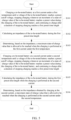
- FIG. 2 is a flowchart of steps of a charge current test method according to an embodiment of this application. This method is applied to the controller 101 of the charge test system 100 shown in FIG. 1 . It needs to be noted that the charge current test method according to this embodiment of this application is not limited to the order shown in FIG. 2 or the order described below.
- the method includes step S101 to step S103.
- Step S101 Charging a to-be-tested battery at a first current under a first temperature until a voltage of the to-be-tested battery reaches a preset cutoff voltage, stopping charging whenever an increment of a state-of-charge value of the to-be-tested battery reaches a preset value during the charging of the to-be-tested battery, and continuing to charge after a duration of stopping charging reaches a first preset time length.
- the first temperature, the first current, the preset value, and the first preset time length may be set as actually required.
- the first temperature is 15 °C (temperature unit: degree Celsius) or 20 °C; and the first current is 30 A (current unit: ampere) or 40 A.
- the preset value may be 5%, 10%, or 20%, and the first preset time length may be any value ranging from 1 to 100 seconds, without being limited in this application.
- the preset cutoff voltage is an upper-limit cutoff voltage of the to-be-tested battery.
- the upper-limit cutoff voltage means a voltage of the battery that reaches a fully charged state while the battery is charged at a specified constant current.
- the upper-limit cutoff voltage makes it convenient to determine a relationship between the first current and the maximum state-of-charge value corresponding to the upper-limit cutoff voltage throughout a process from the start of charging to a moment at which the voltage of the to-be-tested battery being charged reaches the upper-limit cutoff voltage.
- the preset cutoff voltage may be set as required.
- the preset cutoff voltage may be any voltage lower than the upper-limit cutoff voltage of the to-be-tested battery. This is not limited in this application.
- a fully discharged battery with a determined actual capacity may be used as the to-be-tested battery directly.
- the method further includes: estimating a current state-of-charge value of the to-be-tested battery.
- the to-be-tested battery is charged from a state of charge of 20%. Assuming that the current state-of-charge value of the to-be-tested battery is estimated to be 30%, the to-be-tested battery is charged from a state of charge of 30%.
- step S101 in which the to-be-tested battery is charged at the first current under the first temperature specifically includes: charging, at the first current, the to-be-tested battery that has been left to stand for a third preset time length under the first temperature.
- the third preset time length is any time length greater than 1 hour.
- the third preset time length may be 1.3 hours or 1.5 hours, without being limited in this application.
- Step S102 Calculating an impedance of the to-be-tested battery during the first preset time length.
- impedance (the voltage of the to-be-tested battery when the charging is stopped - the voltage of the to-be-tested battery after the charging has been stopped for the first preset time length)/the first current.
- the controller obtains a voltage of the to-be-tested battery through the voltage collection circuit at this time.
- the controller obtains a voltage of the to-be-tested battery again through the voltage collection circuit. Then the controller subtracts the subsequently obtained voltage from the previously obtained voltage to obtain a difference, and divides the difference by the first current at which the to-be-tested battery is charged, so as to obtain the impedance of the to-be-tested battery during the first preset time length.
- the controller obtains a corresponding impedance during each first preset time length in which the charging of the to-be-tested battery is stopped.
- the controller may obtain the impedance during each first preset time length in which the charging is stopped, or, the controller obtains merely voltage values at two end moments during each first preset time length in which the charging is stopped, and then uniformly calculates the impedance of the to-be-tested battery during each time length after the charging is ended.
- the impedance may be calculated by using a difference between the voltages corresponding to two arbitrary moments during the first preset time length, without being limited in this application.
- Step S103 Determining, based on the impedance, a maximum state-of-charge value that is allowed to be reached when the charging is performed at the first current under the first temperature.
- the controller determines, based on the obtained impedance, the maximum state-of-charge value that is allowed to be reached when the charging is performed at the first current under the first temperature.
- the maximum state-of-charge value that is allowed to be reached when the charging is performed at the first current under the first temperature is determined based on the state-of-charge value corresponding to each impedance.
- the preset state-of-charge value is a state value that is set depending on the to-be-tested battery. It needs to be noted that, due to inherent characteristics of the to-be-tested battery, when the state-of-charge value of the to-be-tested battery is in a range of 20% to 60%, the calculated impedance will exhibit a significant numerical fluctuation. Therefore, in order to avoid the impact caused by the fluctuation onto the test result, a state-of-charge value is set, and the maximum state-of-charge value that is allowed to be reached when the charging is performed at the first current under the first temperature is determined based on the impedance change subsequent to the preset state-of-charge value.
- the state-of-charge value may be 50% or 60%, without being limited in this application.
- the state-of-charge value corresponding to the previous impedance value is the maximum state-of-charge value that is allowed to be reached when the charging is performed at the first current under the first temperature.
- a reason for the decrease in impedance lies in a side reaction occurring during the charging of the to-be-tested battery (a side reaction process is equivalent to adding a parallel branch, thereby reducing the overall impedance).
- a side reaction process is equivalent to adding a parallel branch, thereby reducing the overall impedance.
- the state of charge of 90% in FIG. 3 is determined to be the maximum state-of-charge value that is reachable when the charging is performed at the first current.
- the controller obtains a voltage of the to-be-tested battery through the voltage collection circuit at this time.
- the controller obtains a voltage of the to-be-tested battery again through the voltage collection circuit. Then the controller subtracts the subsequently obtained voltage from the previously obtained voltage to obtain a difference, and divides the difference by the second current at which the to-be-tested battery is charged, so as to obtain the impedance of the to-be-tested battery during the first preset time length.
- the first data group includes the first temperature, the first current, and the maximum state-of-charge value that is allowed to be reached when the charging is performed at the first current under the first temperature.
- the second data group includes the second temperature, the second current, and the maximum state-of-charge value that is allowed to be reached when the charging is performed at the second current under the second temperature.
- a charge current matrix table can be constructed based on the two data groups. For the charge current matrix table, refer to Table 1.
- SOC 11 represents the maximum state-of-charge value that is allowed to be reached when the charging is performed at the first current under the first temperature
- SOC 22 represents the maximum state-of-charge value that is allowed to be reached when the charging is performed at the second current under the second temperature.
- Table 1 may be stored in the controller.
- the controller may control the charge current of a target battery of the same type as the to-be-tested battery based on the data in Table 1, thereby ensuring that the target battery is always charged at a safe charge current. For example, when the target battery needs to be charged to a state of charge of SOC 11 under the first temperature, the target battery is charged at a current less than or equal to the first current.
- the charge current test method according to this embodiment of this application can be used to test the to-be-tested battery at other current values under other temperature values, or to test the to-be-tested battery by controlling different temperatures under the same current, or to test the to-be-tested battery by controlling different currents under the same temperature.
- a charge current matrix table containing more data may be constructed based on the foregoing test results.
- Step 1 Obtaining a to-be-tested battery, and then testing an actual capacity of the to-be-tested battery. Specifically, the to-be-tested battery is discharged at a constant current under the room temperature (the discharge rate may be 0.04 C to 1.0 C) until the lower-limit cutoff voltage, and then the to-be-tested battery is charged at a constant current (the charge rate may be 0.04 C to 1.0 C) until the upper-limit cutoff voltage, and then the to-be-tested battery is charged at a constant voltage equal to the upper-limit cutoff voltage until the current reaches a minimum rate (0.01 C to 0.1 C).
- the discharge rate may be 0.04 C to 1.0 C
- the to-be-tested battery is charged at a constant current (the charge rate may be 0.04 C to 1.0 C) until the upper-limit cutoff voltage
- the to-be-tested battery is charged at a constant voltage equal to the upper-limit cutoff voltage until the current reaches a minimum rate (0.01 C to 0.1 C).
- Step 2 Leaving the to-be-tested battery to stand under a room temperature for a second preset time length to ensure that the to-be-tested battery reaches thermal equilibrium under the room temperature.
- Step 4 Charging the to-be-tested battery at the first current by starting from a state of charge of 0% of the to-be-tested battery.
- the increment of the state-of-charge value of the to-be-tested battery reaches a preset value, stopping charging for a first preset time length, then recording a voltage variation that occurs before and after an elapse of the first preset time length of standing, and calculating an impedance corresponding to the current voltage variation. Then continuing to charge.
- the increment of the state-of-charge value of the to-be-tested battery reaches the preset value again, stopping charging for the first preset time length, then recording a voltage variation that occurs before and after an elapse of the first preset time length of standing, and calculating an impedance corresponding to the current voltage variation, and so on, and then continuing the test in this way until the voltage of the to-be-tested battery reaches the preset cutoff voltage.
- the maximum state-of-charge value SOC 11 that is allowed to be reached when the charging is performed at the first current under the first temperature can be determined based on all impedances.
- Step 5 Changing the test temperature and/or charge current, and repeating steps 2 to 4 above to obtain SOC 12, SOC 21, ..., SOC m1, ..., SOC 1n, ..., and SOC mn separately.
- Step 6 Constructing a charge current matrix table (as shown in Table 2) based on all the data.
- Table 2 may be stored in the controller.
- the controller may control the charge current of a target battery of the same type as the to-be-tested battery based on the data in Table 2, thereby ensuring that the target battery is always charged at a safe charge current.
- the charging is stopped whenever the increment of the state-of-charge value of the to-be-tested battery reaches the preset value while the to-be-tested battery is charged at the first current under the first temperature.
- the charging is continued after the duration of stopping charging reaches the first preset time length.
- the impedance during each first preset time length is calculated, and the maximum state-of-charge value that is allowed to be reached when the charging is performed at the first current under the first temperature is determined based on the impedance. In this way, the impedance change of the to-be-tested battery during the charging can be determined.
- the foregoing solution enables direct test of most commercial batteries on the market without a need to manufacture a special-purpose three-electrode battery.
- the solution takes temperature into account, thereby improving accuracy of test results.
- the solution can also test batteries that have aged in any aging state, and is widely applicable.
- a charge current test device 300 includes a charge control module 301, a calculation module 302, and a determining module 303.
- the charge control module 301 is further configured to charge a to-be-tested battery at a second current under a second temperature until a voltage of the to-be-tested battery reaches a preset cutoff voltage, stop charging whenever an increment of a state-of-charge value of the to-be-tested battery reaches a preset value during the charging of the to-be-tested battery, and continue to charge after a duration of stopping charging reaches a first preset time length.
- the calculation module 302 is further configured to calculate the impedance of the to-be-tested battery during the first preset time length while the charging is performed at the second current.
- the determining module 303 is further configured to determine, based on the impedance obtained by charging at the second current, a maximum state-of-charge value that is allowed to be reached when the charging is performed at the second current under the second temperature.
- the device further includes a construction module.
- the construction module is configured to: after determining, based on the impedance obtained by charging at the second current, the maximum state-of-charge value that is allowed to be reached when the charging is performed at the second current under the second temperature, construct a charge current matrix table based on the first temperature, the first current, the second temperature, the second current, the maximum state-of-charge value that is allowed to be reached when the charging is performed at the first current under the first temperature, and the maximum state-of-charge value that is allowed to be reached when the charging is performed at the second current under the second temperature.
Landscapes
- Engineering & Computer Science (AREA)
- Power Engineering (AREA)
- Physics & Mathematics (AREA)
- General Physics & Mathematics (AREA)
- Charge And Discharge Circuits For Batteries Or The Like (AREA)
- Secondary Cells (AREA)
Claims (8)
- Ladestromprüfverfahren, umfassend:Laden (S101) einer zu prüfenden Batterie mit einem ersten Strom unter einer ersten Temperatur, bis eine Spannung der zu prüfenden Batterie eine vorab festgelegte Abschaltspannung erreicht, Stoppen des Ladens immer dann, wenn eine Erhöhung eines Ladezustandswerts der zu prüfenden Batterie einen vorab festgelegten Wert während dem Laden der zu prüfenden Batterie erreicht, und Fortsetzen des Ladens, nachdem eine Dauer des Stoppens des Ladens eine erste vorab festgelegte Zeitdauer erreicht;Berechnen (S102) einer Impedanz der zu prüfenden Batterie durch die Formel Impedanz = (die Spannung der zu prüfenden Batterie, wenn das Laden gestoppt wird - die Spannung der zu prüfenden Batterie, nachdem das Laden für die erste vorab festgelegte Zeitdauer gestoppt wurde)/der erste Strom, bei jedem Ladezustandswert während der ersten vorab festgelegten Zeitdauer; undBestimmen (S103), basierend auf der Impedanz, eines maximalen Ladezustandswerts, der erreicht werden darf, wenn das Laden mit dem ersten Strom unter der ersten Temperatur durchgeführt wird, wobei dieses Bestimmen Folgendes umfasst:Erhalten eines Ladezustandswerts entsprechend jeder der Impedanzen; undBestimmen, wenn eine Impedanz entsprechend einem nächsten Ladezustandswert geringer als eine Impedanz entsprechend einem vorherigen Ladezustandswert für eine erste Zeit nach einem vorab festgelegten Ladezustandswert ist, dass der maximale Ladezustandswert der vorherige Ladezustandswert ist; oder Bestimmen, wenn eine Impedanz entsprechend jedem nächsten Ladezustandswert größer als eine Impedanz entsprechend einem vorherigen Ladezustandswert nach einem vorab festgelegten Ladezustandswert ist, dass der maximale Ladezustandswert ein Ladezustandswert ist, der der vorab festgelegten Abschaltspannung entspricht.
- Verfahren nach Anspruch 1, dadurch gekennzeichnet, dass vor dem Laden einer zu prüfenden Batterie mit einem ersten Strom unter einer ersten Temperatur das Verfahren ferner Folgendes umfasst:Erhalten einer tatsächlichen Kapazität der zu prüfenden Batterie unter einer Raumtemperatur; undEntladen der zu prüfenden Batterie, die während einer zweiten vorab festgelegten Zeitdauer unter der Raumtemperatur stehen gelassen wurde, bis die Spannung der zu prüfenden Batterie eine untere Grenzabschaltspannung erreicht.
- Verfahren nach Anspruch 1, dadurch gekennzeichnet, dass das Laden einer zu prüfenden Batterie mit einem ersten Strom unter einer ersten Temperatur Folgendes umfasst:
Laden, mit dem ersten Strom, der zu prüfenden Batterie, die während einer dritten vorab festgelegten Zeitdauer unter der ersten Temperatur stehen gelassen wurde. - Verfahren nach Anspruch 1, dadurch gekennzeichnet, dass das Verfahren ferner Folgendes umfasst:Laden (S104) der zu prüfenden Batterie mit einem zweiten Strom unter einer zweiten Temperatur, bis die Spannung der zu prüfenden Batterie die vorab festgelegte Abschaltspannung erreicht, Stoppen des Ladens immer dann, wenn die Erhöhung des Ladezustandswerts der zu prüfenden Batterie den vorab festgelegten Wert während dem Laden der zu prüfenden Batterie erreicht, und Fortsetzen des Ladens, nachdem die Dauer des Stoppens des Ladens die erste vorab festgelegte Zeitdauer erreicht;Berechnen (S105) der Impedanz der zu prüfenden Batterie durch die Formel Impedanz = (die Spannung der zu prüfenden Batterie, wenn das Laden gestoppt wird - die Spannung der zu prüfenden Batterie nachdem das Laden für die erste vorab festgelegte Zeitdauer gestoppt wurde)/der zweite Strom, während der ersten vorab festgelegten Zeitdauer, während das Laden mit dem zweiten Strom durchgeführt wird; undBestimmen (S106), basierend auf der Impedanz, die durch das Laden mit dem zweiten Strom erhalten wird, eines maximalen Ladezustandswerts, der erreicht werden darf, wenn das Laden mit dem zweiten Strom unter der zweiten Temperatur durchgeführt wird.
- Ladeprüfsystem (100) umfassend eine Ladevorrichtung (10) und eine Temperatursteuervorrichtung (20);wobei die Temperatursteuervorrichtung (20) konfiguriert ist, um eine Prüftemperatur der zu prüfenden Batterie zu steuern; undwobei die Ladevorrichtung (10) Folgendes umfasst:ein Ladesteuermodul (301), das konfiguriert ist, um eine zu prüfende Batterie mit einem ersten Strom unter einer ersten Temperatur zu laden, bis eine Spannung der zu prüfenden Batterie eine vorab festgelegte Abschaltspannung erreicht, das Laden immer dann, wenn eine Erhöhung eines Ladezustandswerts der zu prüfenden Batterie einen vorab festgelegten Wert während dem Laden der zu prüfenden Batterie erreicht, zu stoppen und das Laden fortzusetzen, nachdem eine Dauer des Stoppens des Ladens eine erste vorab festgelegte Zeitdauer erreicht;ein Berechnungsmodul (302), das konfiguriert ist, um eine Impedanz der zu prüfenden Batterie durch die Formel Impedanz = (die Spannung der zu prüfenden Batterie, wenn das Laden gestoppt wird -die Spannung der zu prüfenden Batterie, nachdem das Laden für die erste vorab festgelegte Zeitdauer gestoppt wurde)/der erste Strom bei jedem Ladezustandswert während der ersten vorab festgelegten Zeitdauer zu berechnen; undein Bestimmungsmodul (303), das konfiguriert ist, um basierend auf der Impedanz einen maximalen Ladezustandswert zu bestimmen, der erreicht werden darf, wenn das Laden mit dem ersten Strom unter der ersten Temperatur durchgeführt wird;wobei das Bestimmungsmodul (303) spezifisch konfiguriert ist, um einen Ladezustandswert entsprechend jeder der Impedanzen zu erhalten; und entweder zu bestimmen, wenn eine Impedanz entsprechend einem nächsten Ladezustandswert geringer als eine Impedanz entsprechend einem vorherigen Ladezustandswert für eine erste Zeit nach einem vorab festgelegten Ladezustandswert ist, dass der maximale Ladezustandswert der vorherige Ladezustandswert ist; oder zu bestimmen, wenn eine Impedanz entsprechend jedem nächsten Ladezustandswert größer als eine Impedanz entsprechend einem vorherigen Ladezustandswert nach einem vorab festgelegten Ladezustandswert ist, dass der maximale Ladezustandswert ein Ladezustandswert entsprechend der vorab festgelegten Abschaltspannung ist.
- Ladeprüfsystem (100) nach Anspruch 5, dadurch gekennzeichnet, dass das Ladesteuermodul (301) ferner konfiguriert ist, um: vor dem Laden der zu prüfenden Batterie mit dem ersten Strom unter der ersten Temperatur eine tatsächliche Kapazität der zu prüfenden Batterie unter einer Raumtemperatur zu erhalten; und die zu prüfende Batterie, die während einer zweiten vorab festgelegten Zeitdauer unter der Raumtemperatur stehen gelassen wurde, zu entladen, bis die Spannung der zu prüfenden Batterie eine untere Grenzabschaltspannung erreicht.
- Ladeprüfsystem (100) nach Anspruch 5, dadurch gekennzeichnet, dass das Ladesteuermodul (301) spezifisch konfiguriert ist, um mit dem ersten Strom die zu prüfende Batterie zu laden, die während einer dritten vorab festgelegten Zeitdauer unter der ersten Temperatur stehen gelassen wurde.
- Ladeprüfsystem (100) nach Anspruch 5, dadurch gekennzeichnet, dass das Ladesteuermodul (301) ferner konfiguriert ist, um: die zu prüfende Batterie mit einem zweiten Strom unter einer zweiten Temperatur zu laden, bis die Spannung der zu prüfenden Batterie die vorab festgelegte Abschaltspannung erreicht, das Laden immer dann zu stoppen, wenn die Erhöhung des Ladezustandswerts der zu prüfenden Batterie den vorab festgelegten Wert während dem Laden der zu prüfenden Batterie erreicht, und das Laden fortzusetzen, nachdem die Dauer des Stoppens des Ladens die erste vorab festgelegte Zeitdauer erreicht;das Berechnungsmodul (302) ferner konfiguriert ist, um die Impedanz der zu prüfenden Batterie während der ersten vorab festgelegten Zeitdauer zu berechnen, während das Laden mit dem zweiten Strom durchgeführt wird; unddas Bestimmungsmodul (303) ferner konfiguriert ist, um basierend auf der Impedanz, die durch das Laden mit dem zweiten Strom erhalten wird, einen maximalen Ladezustandswert zu bestimmen, der erreicht werden darf, wenn das Laden mit dem zweiten Strom unter der zweiten Temperatur durchgeführt wird.
Priority Applications (1)
| Application Number | Priority Date | Filing Date | Title |
|---|---|---|---|
| HUE21904626A HUE072948T2 (hu) | 2021-08-11 | 2021-08-11 | Töltõáram vizsgálati eljárás és berendezés, valamint töltéstesztelõ rendszer |
Applications Claiming Priority (1)
| Application Number | Priority Date | Filing Date | Title |
|---|---|---|---|
| PCT/CN2021/112141 WO2023015501A1 (zh) | 2021-08-11 | 2021-08-11 | 一种充电电流的测试方法、装置及充电测试系统 |
Publications (3)
| Publication Number | Publication Date |
|---|---|
| EP4160234A1 EP4160234A1 (de) | 2023-04-05 |
| EP4160234A4 EP4160234A4 (de) | 2023-05-03 |
| EP4160234B1 true EP4160234B1 (de) | 2025-07-02 |
Family
ID=85200486
Family Applications (1)
| Application Number | Title | Priority Date | Filing Date |
|---|---|---|---|
| EP21904626.5A Active EP4160234B1 (de) | 2021-08-11 | 2021-08-11 | Ladestromtestverfahren und -vorrichtung und ladetestsystem |
Country Status (5)
| Country | Link |
|---|---|
| US (1) | US12032034B2 (de) |
| EP (1) | EP4160234B1 (de) |
| CN (1) | CN116529620A (de) |
| HU (1) | HUE072948T2 (de) |
| WO (1) | WO2023015501A1 (de) |
Families Citing this family (6)
| Publication number | Priority date | Publication date | Assignee | Title |
|---|---|---|---|---|
| JP2023136721A (ja) * | 2022-03-17 | 2023-09-29 | 株式会社東芝 | 充電制御方法、充電制御装置及び電池搭載機器 |
| US12442863B2 (en) * | 2023-01-09 | 2025-10-14 | Southwest Research Institute | Systems and methods for battery performance monitoring |
| US12463446B2 (en) * | 2023-05-22 | 2025-11-04 | Lg Energy Solution, Ltd. | Charging control apparatus and charging control method |
| CN116788098A (zh) * | 2023-06-20 | 2023-09-22 | 雷达新能源汽车(浙江)有限公司 | 一种电池充电管理方法、系统及车辆 |
| CN117310507B (zh) * | 2023-11-29 | 2024-03-29 | 上海泰矽微电子有限公司 | 一种充电截止电流估算方法、装置、设备和介质 |
| CN118777911B (zh) * | 2024-09-03 | 2025-01-07 | 港华能源创科(深圳)有限公司 | 一种锌电池的内阻快速测试方法及系统 |
Family Cites Families (17)
| Publication number | Priority date | Publication date | Assignee | Title |
|---|---|---|---|---|
| US5825159A (en) * | 1997-09-29 | 1998-10-20 | Motorola, Inc. | Battery charging method for properly terminating rapid charge |
| CN102323553B (zh) * | 2011-05-31 | 2014-05-28 | 惠州市亿能电子有限公司 | 一种电池峰值功率的测试方法 |
| CN104471829B (zh) * | 2012-07-12 | 2017-03-15 | 日产自动车株式会社 | 二次电池的充电控制方法及充电控制装置 |
| FR3018360B1 (fr) * | 2014-03-07 | 2016-02-26 | Renault Sas | Methode d'estimation d'un etat de charge d'une batterie comportant plusieurs cellules presentant une plage d'utilisation d'etat de charge variable |
| CN105388426A (zh) * | 2015-12-10 | 2016-03-09 | 东软集团股份有限公司 | 估计电池健康寿命soh的方法和装置 |
| CN106125002B (zh) * | 2016-08-23 | 2019-04-05 | 北京新能源汽车股份有限公司 | 动力电池峰值功率的测试方法、装置 |
| CN106680726B (zh) * | 2016-12-22 | 2020-02-07 | 力神动力电池系统有限公司 | 一种锂离子电池循环性能的检验方法 |
| CN111033930B (zh) * | 2017-08-24 | 2024-03-05 | 罗伯特·博世有限公司 | 电池和电池包的荷电状态的估计方法及利用此荷电状态估计方法的电池管理系统 |
| CN109752663A (zh) * | 2017-11-01 | 2019-05-14 | 微宏动力系统(湖州)有限公司 | 一种电池内阻的测量方法 |
| CN110687468B (zh) * | 2018-06-19 | 2021-01-15 | 华为技术有限公司 | 一种电池荷电状态的估计方法及装置 |
| DE102018220251A1 (de) * | 2018-11-26 | 2020-05-28 | Robert Bosch Gmbh | Verfahren und Vorrichtung zur Abschätzung des Gesundheitszustands eines Wechselakkus |
| CN111007417A (zh) * | 2019-12-06 | 2020-04-14 | 重庆大学 | 基于不一致性评估的电池组soh和rul预测方法及系统 |
| CN112083335B (zh) * | 2020-09-28 | 2023-10-17 | 国联汽车动力电池研究院有限责任公司 | 一种车用蓄电池的快充方法及系统 |
| CN112394289B (zh) * | 2020-10-27 | 2021-10-08 | 同济大学 | 一种锂离子电池充电时析锂检测方法 |
| CN112684356B (zh) * | 2020-10-31 | 2024-06-04 | 浙江锋锂新能源科技有限公司 | 一种锂离子电池的循环测试方法 |
| CN113036846B (zh) * | 2021-03-08 | 2023-03-17 | 山东大学 | 基于阻抗检测的锂离子电池智能优化快速充电方法及系统 |
| CN113125981B (zh) * | 2021-04-13 | 2023-11-17 | 三一汽车制造有限公司 | 电池静置方法、装置、电子设备和存储介质 |
-
2021
- 2021-08-11 HU HUE21904626A patent/HUE072948T2/hu unknown
- 2021-08-11 EP EP21904626.5A patent/EP4160234B1/de active Active
- 2021-08-11 WO PCT/CN2021/112141 patent/WO2023015501A1/zh not_active Ceased
- 2021-08-11 CN CN202180080186.4A patent/CN116529620A/zh active Pending
-
2022
- 2022-06-02 US US17/831,359 patent/US12032034B2/en active Active
Also Published As
| Publication number | Publication date |
|---|---|
| CN116529620A (zh) | 2023-08-01 |
| WO2023015501A1 (zh) | 2023-02-16 |
| EP4160234A4 (de) | 2023-05-03 |
| HUE072948T2 (hu) | 2025-12-28 |
| US12032034B2 (en) | 2024-07-09 |
| EP4160234A1 (de) | 2023-04-05 |
| US20230064748A1 (en) | 2023-03-02 |
Similar Documents
| Publication | Publication Date | Title |
|---|---|---|
| US12032034B2 (en) | Charge current test method and device, and charge test system | |
| US12455326B2 (en) | Method and apparatus for detecting lithium plating, and method and apparatus for obtaining polarization proportion | |
| CN111381178B (zh) | 锂离子电池的健康状态的估算方法及系统 | |
| EP2089731B1 (de) | Vorrichtung und verfahren zur bestimmung des ladestatus einer nicht äquilibrierten batterie | |
| CN103969587B (zh) | 一种混合动力车用动力电池soc估算方法 | |
| CN104391252B (zh) | 一种汽车铅酸蓄电池健康状态检测方法 | |
| CN108663620A (zh) | 一种动力电池组荷电状态估算方法及系统 | |
| CN109752663A (zh) | 一种电池内阻的测量方法 | |
| CN109856548B (zh) | 动力电池容量估算方法 | |
| CN105652212A (zh) | 一种动态检测电池组一致性的方法 | |
| CN110515011A (zh) | 一种锂离子动力电池soc的精确估算方法 | |
| CN103884991A (zh) | 一种单体电池直流内阻的测试方法 | |
| JPWO2017033311A1 (ja) | 劣化度推定装置及び劣化度推定方法 | |
| CN108287318A (zh) | 一种基于车辆动力电池包的检测方法及检测系统 | |
| CN113097582B (zh) | 一种电池单体soh值的估算方法及装置 | |
| CN112964994A (zh) | 一种电池最大电流测量方法及装置 | |
| JP2000270491A (ja) | リチウムイオン電池充電方法及びリチウムイオン電池充電装置 | |
| CN112415409A (zh) | 估算电池容量的方法和装置、存储介质及车辆 | |
| CN113799606A (zh) | 电池寿命估算方法、装置及新能源汽车 | |
| CN116718932A (zh) | 一种锂离子电池临界析锂电流的测试方法 | |
| EP4682565A1 (de) | Batteriediagnosevorrichtung und batteriediagnoseverfahren | |
| JP3678045B2 (ja) | 蓄電池の充電方法 | |
| CN119414272A (zh) | 基于动态电压的锂电池soc估计方法及校准装置 | |
| KR20250050520A (ko) | 배터리 진단 장치 및 배터리 진단 방법 | |
| CN117310511A (zh) | 一种钠电池soc估算方法 |
Legal Events
| Date | Code | Title | Description |
|---|---|---|---|
| STAA | Information on the status of an ep patent application or granted ep patent |
Free format text: STATUS: UNKNOWN |
|
| STAA | Information on the status of an ep patent application or granted ep patent |
Free format text: STATUS: THE INTERNATIONAL PUBLICATION HAS BEEN MADE |
|
| PUAI | Public reference made under article 153(3) epc to a published international application that has entered the european phase |
Free format text: ORIGINAL CODE: 0009012 |
|
| STAA | Information on the status of an ep patent application or granted ep patent |
Free format text: STATUS: REQUEST FOR EXAMINATION WAS MADE |
|
| 17P | Request for examination filed |
Effective date: 20220622 |
|
| AK | Designated contracting states |
Kind code of ref document: A1 Designated state(s): AL AT BE BG CH CY CZ DE DK EE ES FI FR GB GR HR HU IE IS IT LI LT LU LV MC MK MT NL NO PL PT RO RS SE SI SK SM TR |
|
| A4 | Supplementary search report drawn up and despatched |
Effective date: 20230330 |
|
| RIC1 | Information provided on ipc code assigned before grant |
Ipc: H02J 7/00 20060101ALI20230324BHEP Ipc: G01R 31/392 20190101ALI20230324BHEP Ipc: G01R 31/387 20190101ALI20230324BHEP Ipc: G01R 31/389 20190101ALI20230324BHEP Ipc: G01R 31/36 20200101AFI20230324BHEP |
|
| STAA | Information on the status of an ep patent application or granted ep patent |
Free format text: STATUS: EXAMINATION IS IN PROGRESS |
|
| 17Q | First examination report despatched |
Effective date: 20240328 |
|
| RAP1 | Party data changed (applicant data changed or rights of an application transferred) |
Owner name: CONTEMPORARY AMPEREX TECHNOLOGY(HONG KONG) LIMITED |
|
| DAV | Request for validation of the european patent (deleted) | ||
| DAX | Request for extension of the european patent (deleted) | ||
| GRAP | Despatch of communication of intention to grant a patent |
Free format text: ORIGINAL CODE: EPIDOSNIGR1 |
|
| STAA | Information on the status of an ep patent application or granted ep patent |
Free format text: STATUS: GRANT OF PATENT IS INTENDED |
|
| INTG | Intention to grant announced |
Effective date: 20250331 |
|
| GRAS | Grant fee paid |
Free format text: ORIGINAL CODE: EPIDOSNIGR3 |
|
| GRAA | (expected) grant |
Free format text: ORIGINAL CODE: 0009210 |
|
| STAA | Information on the status of an ep patent application or granted ep patent |
Free format text: STATUS: THE PATENT HAS BEEN GRANTED |
|
| AK | Designated contracting states |
Kind code of ref document: B1 Designated state(s): AL AT BE BG CH CY CZ DE DK EE ES FI FR GB GR HR HU IE IS IT LI LT LU LV MC MK MT NL NO PL PT RO RS SE SI SK SM TR |
|
| REG | Reference to a national code |
Ref country code: GB Ref legal event code: FG4D |
|
| REG | Reference to a national code |
Ref country code: CH Ref legal event code: EP |
|
| REG | Reference to a national code |
Ref country code: DE Ref legal event code: R096 Ref document number: 602021033591 Country of ref document: DE |
|
| P01 | Opt-out of the competence of the unified patent court (upc) registered |
Free format text: CASE NUMBER: APP_28846/2025 Effective date: 20250617 |
|
| REG | Reference to a national code |
Ref country code: IE Ref legal event code: FG4D |
|
| PGFP | Annual fee paid to national office [announced via postgrant information from national office to epo] |
Ref country code: DE Payment date: 20250827 Year of fee payment: 5 |
|
| PGFP | Annual fee paid to national office [announced via postgrant information from national office to epo] |
Ref country code: NO Payment date: 20250819 Year of fee payment: 5 |
|
| PGFP | Annual fee paid to national office [announced via postgrant information from national office to epo] |
Ref country code: GB Payment date: 20250826 Year of fee payment: 5 |
|
| PGFP | Annual fee paid to national office [announced via postgrant information from national office to epo] |
Ref country code: AT Payment date: 20251020 Year of fee payment: 5 Ref country code: FR Payment date: 20250826 Year of fee payment: 5 |
|
| REG | Reference to a national code |
Ref country code: NL Ref legal event code: MP Effective date: 20250702 |
|
| PGFP | Annual fee paid to national office [announced via postgrant information from national office to epo] |
Ref country code: HU Payment date: 20250807 Year of fee payment: 5 |
|
| PG25 | Lapsed in a contracting state [announced via postgrant information from national office to epo] |
Ref country code: PT Free format text: LAPSE BECAUSE OF FAILURE TO SUBMIT A TRANSLATION OF THE DESCRIPTION OR TO PAY THE FEE WITHIN THE PRESCRIBED TIME-LIMIT Effective date: 20251103 |
|
| PG25 | Lapsed in a contracting state [announced via postgrant information from national office to epo] |
Ref country code: NL Free format text: LAPSE BECAUSE OF FAILURE TO SUBMIT A TRANSLATION OF THE DESCRIPTION OR TO PAY THE FEE WITHIN THE PRESCRIBED TIME-LIMIT Effective date: 20250702 |
|
| REG | Reference to a national code |
Ref country code: AT Ref legal event code: MK05 Ref document number: 1809795 Country of ref document: AT Kind code of ref document: T Effective date: 20250702 |
|
| REG | Reference to a national code |
Ref country code: HU Ref legal event code: AG4A Ref document number: E072948 Country of ref document: HU |
|
| PG25 | Lapsed in a contracting state [announced via postgrant information from national office to epo] |
Ref country code: IS Free format text: LAPSE BECAUSE OF FAILURE TO SUBMIT A TRANSLATION OF THE DESCRIPTION OR TO PAY THE FEE WITHIN THE PRESCRIBED TIME-LIMIT Effective date: 20251102 |
|
| REG | Reference to a national code |
Ref country code: LT Ref legal event code: MG9D |
|
| PG25 | Lapsed in a contracting state [announced via postgrant information from national office to epo] |
Ref country code: AT Free format text: LAPSE BECAUSE OF FAILURE TO SUBMIT A TRANSLATION OF THE DESCRIPTION OR TO PAY THE FEE WITHIN THE PRESCRIBED TIME-LIMIT Effective date: 20250702 |
|
| PG25 | Lapsed in a contracting state [announced via postgrant information from national office to epo] |
Ref country code: FI Free format text: LAPSE BECAUSE OF FAILURE TO SUBMIT A TRANSLATION OF THE DESCRIPTION OR TO PAY THE FEE WITHIN THE PRESCRIBED TIME-LIMIT Effective date: 20250702 |
|
| PG25 | Lapsed in a contracting state [announced via postgrant information from national office to epo] |
Ref country code: HR Free format text: LAPSE BECAUSE OF FAILURE TO SUBMIT A TRANSLATION OF THE DESCRIPTION OR TO PAY THE FEE WITHIN THE PRESCRIBED TIME-LIMIT Effective date: 20250702 |
|
| PG25 | Lapsed in a contracting state [announced via postgrant information from national office to epo] |
Ref country code: GR Free format text: LAPSE BECAUSE OF FAILURE TO SUBMIT A TRANSLATION OF THE DESCRIPTION OR TO PAY THE FEE WITHIN THE PRESCRIBED TIME-LIMIT Effective date: 20251003 |
|
| PG25 | Lapsed in a contracting state [announced via postgrant information from national office to epo] |
Ref country code: CZ Free format text: LAPSE BECAUSE OF FAILURE TO SUBMIT A TRANSLATION OF THE DESCRIPTION OR TO PAY THE FEE WITHIN THE PRESCRIBED TIME-LIMIT Effective date: 20250702 Ref country code: SE Free format text: LAPSE BECAUSE OF FAILURE TO SUBMIT A TRANSLATION OF THE DESCRIPTION OR TO PAY THE FEE WITHIN THE PRESCRIBED TIME-LIMIT Effective date: 20250702 |
|
| PG25 | Lapsed in a contracting state [announced via postgrant information from national office to epo] |
Ref country code: LV Free format text: LAPSE BECAUSE OF FAILURE TO SUBMIT A TRANSLATION OF THE DESCRIPTION OR TO PAY THE FEE WITHIN THE PRESCRIBED TIME-LIMIT Effective date: 20250702 |
|
| PG25 | Lapsed in a contracting state [announced via postgrant information from national office to epo] |
Ref country code: BG Free format text: LAPSE BECAUSE OF FAILURE TO SUBMIT A TRANSLATION OF THE DESCRIPTION OR TO PAY THE FEE WITHIN THE PRESCRIBED TIME-LIMIT Effective date: 20250702 Ref country code: PL Free format text: LAPSE BECAUSE OF FAILURE TO SUBMIT A TRANSLATION OF THE DESCRIPTION OR TO PAY THE FEE WITHIN THE PRESCRIBED TIME-LIMIT Effective date: 20250702 |
|
| PG25 | Lapsed in a contracting state [announced via postgrant information from national office to epo] |
Ref country code: RS Free format text: LAPSE BECAUSE OF FAILURE TO SUBMIT A TRANSLATION OF THE DESCRIPTION OR TO PAY THE FEE WITHIN THE PRESCRIBED TIME-LIMIT Effective date: 20251002 |
|
| PG25 | Lapsed in a contracting state [announced via postgrant information from national office to epo] |
Ref country code: ES Free format text: LAPSE BECAUSE OF FAILURE TO SUBMIT A TRANSLATION OF THE DESCRIPTION OR TO PAY THE FEE WITHIN THE PRESCRIBED TIME-LIMIT Effective date: 20250702 |
|
| PG25 | Lapsed in a contracting state [announced via postgrant information from national office to epo] |
Ref country code: RO Free format text: LAPSE BECAUSE OF FAILURE TO SUBMIT A TRANSLATION OF THE DESCRIPTION OR TO PAY THE FEE WITHIN THE PRESCRIBED TIME-LIMIT Effective date: 20250702 |
|
| REG | Reference to a national code |
Ref country code: CH Ref legal event code: H13 Free format text: ST27 STATUS EVENT CODE: U-0-0-H10-H13 (AS PROVIDED BY THE NATIONAL OFFICE) Effective date: 20260324 |
|
| PG25 | Lapsed in a contracting state [announced via postgrant information from national office to epo] |
Ref country code: SM Free format text: LAPSE BECAUSE OF FAILURE TO SUBMIT A TRANSLATION OF THE DESCRIPTION OR TO PAY THE FEE WITHIN THE PRESCRIBED TIME-LIMIT Effective date: 20250702 |
|
| PG25 | Lapsed in a contracting state [announced via postgrant information from national office to epo] |
Ref country code: DK Free format text: LAPSE BECAUSE OF FAILURE TO SUBMIT A TRANSLATION OF THE DESCRIPTION OR TO PAY THE FEE WITHIN THE PRESCRIBED TIME-LIMIT Effective date: 20250702 |
|
| PG25 | Lapsed in a contracting state [announced via postgrant information from national office to epo] |
Ref country code: LU Free format text: LAPSE BECAUSE OF NON-PAYMENT OF DUE FEES Effective date: 20250811 Ref country code: IT Free format text: LAPSE BECAUSE OF FAILURE TO SUBMIT A TRANSLATION OF THE DESCRIPTION OR TO PAY THE FEE WITHIN THE PRESCRIBED TIME-LIMIT Effective date: 20250702 |
|
| PG25 | Lapsed in a contracting state [announced via postgrant information from national office to epo] |
Ref country code: CH Free format text: LAPSE BECAUSE OF NON-PAYMENT OF DUE FEES Effective date: 20250831 |
|
| PG25 | Lapsed in a contracting state [announced via postgrant information from national office to epo] |
Ref country code: SK Free format text: LAPSE BECAUSE OF FAILURE TO SUBMIT A TRANSLATION OF THE DESCRIPTION OR TO PAY THE FEE WITHIN THE PRESCRIBED TIME-LIMIT Effective date: 20250702 Ref country code: EE Free format text: LAPSE BECAUSE OF FAILURE TO SUBMIT A TRANSLATION OF THE DESCRIPTION OR TO PAY THE FEE WITHIN THE PRESCRIBED TIME-LIMIT Effective date: 20250702 |
|
| PLBE | No opposition filed within time limit |
Free format text: ORIGINAL CODE: 0009261 |
|
| STAA | Information on the status of an ep patent application or granted ep patent |
Free format text: STATUS: NO OPPOSITION FILED WITHIN TIME LIMIT |