EP4159989A2 - Variable compression-ratio device - Google Patents
Variable compression-ratio device Download PDFInfo
- Publication number
- EP4159989A2 EP4159989A2 EP22195501.6A EP22195501A EP4159989A2 EP 4159989 A2 EP4159989 A2 EP 4159989A2 EP 22195501 A EP22195501 A EP 22195501A EP 4159989 A2 EP4159989 A2 EP 4159989A2
- Authority
- EP
- European Patent Office
- Prior art keywords
- crankshaft
- oil
- gear
- variable compression
- ratio device
- Prior art date
- Legal status (The legal status is an assumption and is not a legal conclusion. Google has not performed a legal analysis and makes no representation as to the accuracy of the status listed.)
- Granted
Links
- 239000003921 oil Substances 0.000 claims abstract description 89
- 239000010687 lubricating oil Substances 0.000 claims abstract description 27
- 238000002485 combustion reaction Methods 0.000 claims abstract description 11
- 230000002093 peripheral effect Effects 0.000 claims description 13
- 230000000694 effects Effects 0.000 description 6
- 230000005540 biological transmission Effects 0.000 description 5
- 238000010586 diagram Methods 0.000 description 3
- 230000003749 cleanliness Effects 0.000 description 2
- 238000005461 lubrication Methods 0.000 description 2
- 238000004519 manufacturing process Methods 0.000 description 2
- 230000006835 compression Effects 0.000 description 1
- 238000007906 compression Methods 0.000 description 1
- 230000006866 deterioration Effects 0.000 description 1
- 238000006073 displacement reaction Methods 0.000 description 1
- 239000000945 filler Substances 0.000 description 1
- 239000000446 fuel Substances 0.000 description 1
- 230000001050 lubricating effect Effects 0.000 description 1
- 230000002265 prevention Effects 0.000 description 1
Images

Classifications
-
- F—MECHANICAL ENGINEERING; LIGHTING; HEATING; WEAPONS; BLASTING
- F02—COMBUSTION ENGINES; HOT-GAS OR COMBUSTION-PRODUCT ENGINE PLANTS
- F02B—INTERNAL-COMBUSTION PISTON ENGINES; COMBUSTION ENGINES IN GENERAL
- F02B75/00—Other engines
- F02B75/04—Engines with variable distances between pistons at top dead-centre positions and cylinder heads
- F02B75/048—Engines with variable distances between pistons at top dead-centre positions and cylinder heads by means of a variable crank stroke length
Definitions
- the present invention relates to variable compression-ratio devices.
- crankshaft support structure of an internal combustion engine including an oil channel for supplying lubricating oil to a crankshaft bearing portion or the like
- Japanese Patent Laid-Open No. 2012-36934 There has also been disclosed a configuration of a multi-link variable-compression-ratio engine in which outflow of lubricating oil into the combustion chamber can be prevented, and oil deterioration due to blowby gas containing unburned fuel can be reduced (for example, Japanese Patent Laid-Open No. 2009-503971 ).
- variable compression-ratio device in which an eccentric cam is provided between the crank pin of the crankshaft and the large end of the connecting rod, and a motor rotates the eccentric cam to change the distance between the center axis of the large end and the axis of the crankshaft.
- the present invention has been made in light of such circumstances, and an object thereof is to provide oil supply to the variable compression-ratio device.
- An aspect of the present invention is a variable compression-ratio device including: a gear shaft disposed inside a crankshaft of an internal combustion engine coaxially with the crankshaft and configured to be rotationally driven by a power source; an input gear connected to the gear shaft; an intermediate gear supported by a crank web of the crankshaft and engaged with the input gear; an eccentric cam disposed between a crank pin of the crankshaft and a large end of a connecting rod and engaged with the intermediate gear; and a first oil channel configured to supply lubricating oil to the input gear.
- crankshaft is provided with a first oil channel for supplying lubricating oil to the input gear, it is possible to supply oil to an input gear of the variable compression-ratio device.
- FIG. 1 is a diagram illustrating the internal structure of a power unit 10 including a variable compression-ratio device 10a of the present embodiment.
- This power unit 10 is configured to be mounted on a motorcycle and includes an engine 11 which is an internal combustion engine.
- the application of this power unit is not limited to motorcycles but may be mounted on various types of saddle-ride vehicle including three-wheeled and four-wheeled ones.
- the engine 11 includes a crank case 15 that supports a crankshaft 12 via a plurality of bearings 13 and 14 so that the crankshaft 12 is rotatable and a cylinder portion 20 that houses a not-illustrated piston connected to the crankshaft 12 via a crank web 16, a crank pin 17, and a connecting rod 18 in this order such that the piston is slidable.
- FIG. 1 illustrates a horizontal engine 11 in which the cylinder portion 20 protrudes forward horizontally from the crank case 15.
- the symbol C1 indicates the axis of the crankshaft 12 supported by the crank case 15.
- the symbol C2 indicates the axis of the crank pin 17.
- the axis C1 of the crankshaft 12 and the axis C2 of the crank pin 17 are parallel.
- the variable compression-ratio device 10a includes an eccentric cam 31 between the outer periphery of the crank pin 17 of the crankshaft 12 and the inner periphery of the large end 18a of the connecting rod 18.
- the variable compression-ratio device 10a also includes a motor 32 that serves as the power source of the eccentric cam 31 and a power transmission mechanism 33 that transmits the power of the motor 32 to the eccentric cam 31.
- the power transmission mechanism 33 includes a gear shaft 52 coaxially disposed inside the crankshaft 12 of the internal combustion engine 11, an input gear 51 connected to an end portion of the gear shaft 52, an intermediate gear 50 supported by the crank web 16 of the crankshaft 12 and engaged with the input gear 51, and the aforementioned eccentric cam 31 engaged with the intermediate gear 50.
- the gear shaft 52 is disposed inside the crankshaft 12 coaxially with the crankshaft 12 and rotatably supported via a pair of bearings 56 and 57.
- This gear shaft 52 passes through a cover 58 located on the right side of the crankshaft 12 and extends to a position near the motor 32.
- an oil indicated by the symbol J in FIG. 1
- this oil lubricates each of the bearings 56 and 57.
- a driving-side gear portion 53 has a warm gear 53a connected to the proximal end of the gear shaft 52 with a key, and this warm gear 53a reduces the rotation speed of a warm wheel attached to the motor 32 and transmits the rotation to the gear shaft 52.
- the configuration of the driving-side gear portion 53 is not limited to the one using the warm gear 53a, but a known speed reducing mechanism can be adopted as appropriate. Although this example is based on a case in which the power source is the motor 32, the power source does not necessarily have to be the motor 32.
- the rotation angle of the motor 32 is controlled by a control unit 41 mounted on the motorcycle.
- This control unit 41 obtains the rotation position of a part of the power transmission mechanism 33 (the rotation position of the gear shaft 52 in this configuration) via a potentiometer 42, and based on the obtained rotation position, this control unit 41 controls the rotation of the motor 32 such that it is at the target position.
- the control unit 41 is, for example, an electronic control unit (ECU) provided on the motorcycle.
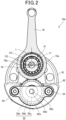
- FIG. 2 is a cross-sectional view taken along line II-II in FIG. 1 , illustrating the crank pin 17, the eccentric cam 31, and their peripheral configurations.
- the thickness t of the eccentric cam 31 gradually changes in the circumferential direction.
- the power is transmitted to the eccentric cam 31 via the power transmission mechanism 33, the eccentric cam 31 rotates in the circumferential direction.
- the thickness t of the eccentric cam 31 changes in the circumferential direction, and the position of the center axis Co of the large end 18a of the connecting rod 18 is displaced from the axis C2 of the crank pin 17 to the position of the eccentric axis C 3 , which is shifted from the axis C2.
- This displacement changes the distance between the center axis Co of the large end 18a and the axis C1 of the crankshaft 12, and this changes the stroke of the piston, changing the compression ratio.
- the outer periphery of the eccentric cam 31 has a gear portion 31a, as illustrated in FIG. 1 .
- the gear portion 31a of the eccentric cam 31 engages with a large diameter gear 50a of the intermediate gear 50, and a small diameter gear 50b of the intermediate gear 50 engages with the input gear 51 of the gear shaft 52.
- the intermediate gear 50 is a double gear including the large diameter gear 50a and the small diameter gear 50b.
- the intermediate gear 50 is covered with a cover member 62.
- the cover member 62 is fastened to the crank web 16 by fasteners 54 such that the intermediate gear 50 is sandwiched between the cover member 62 and the crank web 16.
- the fasteners 54 function as coming-off prevention parts that prevent the intermediate gear 50 from coming off.
- peripheral edge portion 62a of the cover member 62 including the lower portion is closely joined to the crank web 16 and sealed with a gasket or a filler.
- the space between the crank web 16 and the cover member 62 serves as an oil sump 63 of lubricating oil.
- the lubricating oil gathered near the intermediate gear 50 by the oil sump 63 improves the initial lubrication property of the variable compression-ratio device at the time when the internal combustion engine 11 restarts.
- the gear shaft 52 is disposed in a through hole 71 of the crankshaft 12. Between the inner periphery of the through hole 71 of the crankshaft 12 and the outer periphery of the gear shaft 52 is formed an annular third oil channel 73.
- the third oil channel 73 is provided with oil (indicated by the symbol J in FIG. 1 ) from a not-illustrated oil pump disposed in the power unit 10.
- the third oil channel 73 communicates with a fourth oil channel 74 and fifth oil channel 75 in the form of small holes, formed in the crankshaft 12.
- the fourth oil channel 74 and the fifth oil channel 75 communicate with an annular sixth oil channel 76.
- the annular sixth oil channel 76 is formed between the primary gear collar 60 for positioning the primary gear 21 and the outer periphery of the crankshaft 12. Since the sixth oil channel 76 is provided inside the primary gear collar 60, the number of parts forming the oil channel can be reduced, providing effects of improving manufacturing efficiency.
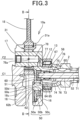
- the sixth oil channel 76 communicates with a first oil guide channel 65 formed in the crankshaft 12 illustrated at a lower portion of FIG. 3 and communicates with a second oil guide channel 67 also formed in the crankshaft 12, illustrated at an upper portion in FIG. 3 .
- the first oil guide channel 65 extends being inclined toward the axis C1 of the crankshaft 12 and along the crankshaft 12. At the end portion on the input gear 51 side of the first oil guide channel 65 is provided an orifice 64.
- the orifice 64 is provided in the crank web 16.
- the orifice 64 has an opening at a position facing the tooth surface of the input gear 51. It is desirable that the diameter of the orifice 64 be smaller than or equal to 1 mm.
- Lubricating oil provided in the first oil guide channel 65 is provided onto the tooth surface of the input gear 51 of the variable compression-ratio device 10a through the orifice 64. Since lubricating oil is provided through the orifice 64, the amount of lubricating oil is adjusted, and the oil supply can be reliable.
- first oil guide channel 65 is inclined toward the axis C1 of the crankshaft 12, foreign objects contained in lubricating oil tend to stick to the inner peripheral surface of the first oil guide channel 65 by centrifugal force, and thus it is possible to keep the cleanliness of lubricating oil provided to the variable compression-ratio device 10a.
- a "first oil channel 5" is provided at a peripheral portion of the crank web 16 and includes the annular third oil channel 73, the fourth oil channel 74 in the form of a small hole, the annular sixth oil channel 76, the first oil guide channel 65, and the orifice 64.
- the first oil channel 5 has a simple, compact structure.
- the second oil guide channel 67 extends being inclined toward the axis C1 of the crankshaft and along the crankshaft 12.
- the second oil guide channel 67 bends in the middle and communicates with a seventh oil channel 77 formed in the crank pin 17 and an eighth oil channel 78 orthogonal to the seventh oil channel 77.
- the lubricating oil supplied in the eighth oil channel 78 is supplied to the inner peripheral surface of the large end 18a of the connecting rod 18 through a hole 78a.
- the second oil guide channel 67 is inclined toward the axis C1 of the crankshaft. Hence, foreign objects contained in lubricating oil tend to stick to the inner peripheral surface of the second oil guide channel 67 by centrifugal force. Thus, it is possible to keep the cleanliness of the lubricating oil supplied to the crank pin 17.
- a “second oil channel 7" includes the annular third oil channel 73 provided at a peripheral portion of the crank web 16, the fifth oil channel 75 in the form of a small hole, the annular sixth oil channel 76, the second oil guide channel 67, the seventh oil channel 77, and the eighth oil channel 78.
- the second oil channel 7 has a simple, compact structure.
- the above embodiment supports the following configurations.
- a variable compression-ratio device including: a gear shaft disposed inside a crankshaft of an internal combustion engine coaxially with the crankshaft and configured to be rotationally driven by a power source; an input gear connected to the gear shaft; an intermediate gear supported by a crank web of the crankshaft and engaged with the input gear; an eccentric cam disposed between a crank pin of the crankshaft and a large end of a connecting rod and engaged with the intermediate gear; and a first oil channel provided in the crankshaft and configured to supply lubricating oil to the input gear.
- This configuration makes it possible to reliably supply oil to the input gear.
- This configuration makes it possible to form the first oil channel with a compact structure.
- This configuration provides effects of reducing the part count and improving the manufacturing efficiency.
- This configuration makes it easy to adjust the amount of lubricating oil and provides effects of reliably supplying oil to the variable compression-ratio device.
- variable compression-ratio device Since with this configuration, lubricating oil is gathered near the intermediate gear when the internal combustion engine restarts, the initial lubrication property of the variable compression-ratio device is improved.
Landscapes
- Engineering & Computer Science (AREA)
- Chemical & Material Sciences (AREA)
- Combustion & Propulsion (AREA)
- Mechanical Engineering (AREA)
- General Engineering & Computer Science (AREA)
- Output Control And Ontrol Of Special Type Engine (AREA)
- Lubrication Of Internal Combustion Engines (AREA)
- Shafts, Cranks, Connecting Bars, And Related Bearings (AREA)
Abstract
Description
- The present invention relates to variable compression-ratio devices.
- There has been known a crankshaft support structure of an internal combustion engine including an oil channel for supplying lubricating oil to a crankshaft bearing portion or the like (for example,
Japanese Patent Laid-Open No. 2012-36934 Japanese Patent Laid-Open No. 2009-503971 - Unfortunately, the above structure does not take supplying oil to the variable compression-ratio device into account.
- The present invention has been made in light of such circumstances, and an object thereof is to provide oil supply to the variable compression-ratio device.
- An aspect of the present invention is a variable compression-ratio device including: a gear shaft disposed inside a crankshaft of an internal combustion engine coaxially with the crankshaft and configured to be rotationally driven by a power source; an input gear connected to the gear shaft; an intermediate gear supported by a crank web of the crankshaft and engaged with the input gear; an eccentric cam disposed between a crank pin of the crankshaft and a large end of a connecting rod and engaged with the intermediate gear; and a first oil channel configured to supply lubricating oil to the input gear.
- Since the crankshaft is provided with a first oil channel for supplying lubricating oil to the input gear, it is possible to supply oil to an input gear of the variable compression-ratio device.
-
-
FIG. 1 is a diagram illustrating the internal structure of a variable compression-ratio device of the present invention; -
FIG. 2 is a diagram illustrating a crank pin, an eccentric cam, and their peripheral configurations; and -
FIG. 3 is an enlarged view of an input gear and its vicinities of the variable compression-ratio device. - Hereinafter, an embodiment of the present invention will be described with reference to the drawings. Note that in the following description, mentioning of directions such as frontrear, right-left, and upper-lower means the same directions as the ones with respect to the vehicle body unless otherwise specified. In each drawing, the symbol FR indicates the front side of the vehicle body, the symbol UP indicates the upper side of the vehicle body, and the symbol LH indicates the left side of the vehicle body.
-
FIG. 1 is a diagram illustrating the internal structure of apower unit 10 including a variable compression-ratio device 10a of the present embodiment. Thispower unit 10 is configured to be mounted on a motorcycle and includes anengine 11 which is an internal combustion engine. The application of this power unit is not limited to motorcycles but may be mounted on various types of saddle-ride vehicle including three-wheeled and four-wheeled ones. - The
engine 11 includes acrank case 15 that supports acrankshaft 12 via a plurality ofbearings crankshaft 12 is rotatable and acylinder portion 20 that houses a not-illustrated piston connected to thecrankshaft 12 via acrank web 16, acrank pin 17, and a connectingrod 18 in this order such that the piston is slidable. - The
crankshaft 12 supports aprimary gear 21 engaged with a not-illustrated driven gear. Between thisprimary gear 21 and thebearing 13 that supports thecrankshaft 12 is aprimary gear collar 60 for positioning theprimary gear 21.FIG. 1 illustrates ahorizontal engine 11 in which thecylinder portion 20 protrudes forward horizontally from thecrank case 15. - In
FIG. 1 , the symbol C1 indicates the axis of thecrankshaft 12 supported by thecrank case 15. The symbol C2 indicates the axis of thecrank pin 17. The axis C1 of thecrankshaft 12 and the axis C2 of thecrank pin 17 are parallel. - The variable compression-
ratio device 10a includes aneccentric cam 31 between the outer periphery of thecrank pin 17 of thecrankshaft 12 and the inner periphery of thelarge end 18a of the connectingrod 18. The variable compression-ratio device 10a also includes amotor 32 that serves as the power source of theeccentric cam 31 and apower transmission mechanism 33 that transmits the power of themotor 32 to theeccentric cam 31. - The
power transmission mechanism 33 includes agear shaft 52 coaxially disposed inside thecrankshaft 12 of theinternal combustion engine 11, aninput gear 51 connected to an end portion of thegear shaft 52, anintermediate gear 50 supported by thecrank web 16 of thecrankshaft 12 and engaged with theinput gear 51, and the aforementionedeccentric cam 31 engaged with theintermediate gear 50. - The
gear shaft 52 is disposed inside thecrankshaft 12 coaxially with thecrankshaft 12 and rotatably supported via a pair ofbearings gear shaft 52 passes through acover 58 located on the right side of thecrankshaft 12 and extends to a position near themotor 32. Inside thecover 58 is provided an oil (indicated by the symbol J inFIG. 1 ) from a not-illustrated oil pump provided in thepower unit 10, and this oil lubricates each of thebearings - A driving-
side gear portion 53 has awarm gear 53a connected to the proximal end of thegear shaft 52 with a key, and thiswarm gear 53a reduces the rotation speed of a warm wheel attached to themotor 32 and transmits the rotation to thegear shaft 52. Note that the configuration of the driving-side gear portion 53 is not limited to the one using thewarm gear 53a, but a known speed reducing mechanism can be adopted as appropriate. Although this example is based on a case in which the power source is themotor 32, the power source does not necessarily have to be themotor 32. - The rotation angle of the
motor 32 is controlled by acontrol unit 41 mounted on the motorcycle. Thiscontrol unit 41 obtains the rotation position of a part of the power transmission mechanism 33 (the rotation position of thegear shaft 52 in this configuration) via apotentiometer 42, and based on the obtained rotation position, thiscontrol unit 41 controls the rotation of themotor 32 such that it is at the target position. Thecontrol unit 41 is, for example, an electronic control unit (ECU) provided on the motorcycle. - Next, the
eccentric cam 31, thepower transmission mechanism 33, and their peripheral configurations will be described. -
FIG. 2 is a cross-sectional view taken along line II-II inFIG. 1 , illustrating thecrank pin 17, theeccentric cam 31, and their peripheral configurations. - As illustrated in
FIG. 2 , the thickness t of theeccentric cam 31 gradually changes in the circumferential direction. When themotor 32 is driven, the power is transmitted to theeccentric cam 31 via thepower transmission mechanism 33, theeccentric cam 31 rotates in the circumferential direction. - At the reference position, the position of the center axis Co of the
large end 18a of the connectingrod 18 is in agreement with the position of the axis C2 of thecrank pin 17. - When the
eccentric cam 31 rotates, the thickness t of theeccentric cam 31 changes in the circumferential direction, and the position of the center axis Co of thelarge end 18a of the connectingrod 18 is displaced from the axis C2 of thecrank pin 17 to the position of the eccentric axis C3, which is shifted from the axis C2. This displacement changes the distance between the center axis Co of thelarge end 18a and the axis C1 of thecrankshaft 12, and this changes the stroke of the piston, changing the compression ratio. - The outer periphery of the
eccentric cam 31 has agear portion 31a, as illustrated inFIG. 1 . Thegear portion 31a of theeccentric cam 31 engages with alarge diameter gear 50a of theintermediate gear 50, and asmall diameter gear 50b of theintermediate gear 50 engages with theinput gear 51 of thegear shaft 52. Theintermediate gear 50 is a double gear including thelarge diameter gear 50a and thesmall diameter gear 50b. - As illustrated in
FIG. 2 , at least part (a lower half) of theintermediate gear 50 is covered with acover member 62. Thecover member 62 is fastened to thecrank web 16 byfasteners 54 such that theintermediate gear 50 is sandwiched between thecover member 62 and thecrank web 16. Thefasteners 54 function as coming-off prevention parts that prevent theintermediate gear 50 from coming off. - The
peripheral edge portion 62a of thecover member 62 including the lower portion is closely joined to thecrank web 16 and sealed with a gasket or a filler. - The space between the
crank web 16 and thecover member 62 serves as an oil sump 63 of lubricating oil. The lubricating oil gathered near theintermediate gear 50 by the oil sump 63 improves the initial lubrication property of the variable compression-ratio device at the time when theinternal combustion engine 11 restarts. - Next, the supply route of the lubricating oil for the variable compression-
ratio device 10a will be described. - As illustrated in
FIG. 3 , thegear shaft 52 is disposed in a throughhole 71 of thecrankshaft 12. Between the inner periphery of thethrough hole 71 of thecrankshaft 12 and the outer periphery of thegear shaft 52 is formed an annularthird oil channel 73. - The
third oil channel 73 is provided with oil (indicated by the symbol J inFIG. 1 ) from a not-illustrated oil pump disposed in thepower unit 10. - The
third oil channel 73 communicates with afourth oil channel 74 andfifth oil channel 75 in the form of small holes, formed in thecrankshaft 12. Thefourth oil channel 74 and thefifth oil channel 75 communicate with an annularsixth oil channel 76. The annularsixth oil channel 76 is formed between theprimary gear collar 60 for positioning theprimary gear 21 and the outer periphery of thecrankshaft 12. Since thesixth oil channel 76 is provided inside theprimary gear collar 60, the number of parts forming the oil channel can be reduced, providing effects of improving manufacturing efficiency. - The
sixth oil channel 76 communicates with a firstoil guide channel 65 formed in thecrankshaft 12 illustrated at a lower portion ofFIG. 3 and communicates with a secondoil guide channel 67 also formed in thecrankshaft 12, illustrated at an upper portion inFIG. 3 . - The first
oil guide channel 65 extends being inclined toward the axis C1 of thecrankshaft 12 and along thecrankshaft 12. At the end portion on theinput gear 51 side of the firstoil guide channel 65 is provided anorifice 64. Theorifice 64 is provided in thecrank web 16. Theorifice 64 has an opening at a position facing the tooth surface of theinput gear 51. It is desirable that the diameter of theorifice 64 be smaller than or equal to 1 mm. - Lubricating oil provided in the first
oil guide channel 65 is provided onto the tooth surface of theinput gear 51 of the variable compression-ratio device 10a through theorifice 64. Since lubricating oil is provided through theorifice 64, the amount of lubricating oil is adjusted, and the oil supply can be reliable. - In addition, since the first
oil guide channel 65 is inclined toward the axis C1 of thecrankshaft 12, foreign objects contained in lubricating oil tend to stick to the inner peripheral surface of the firstoil guide channel 65 by centrifugal force, and thus it is possible to keep the cleanliness of lubricating oil provided to the variable compression-ratio device 10a. - A "
first oil channel 5" is provided at a peripheral portion of thecrank web 16 and includes the annularthird oil channel 73, thefourth oil channel 74 in the form of a small hole, the annularsixth oil channel 76, the firstoil guide channel 65, and theorifice 64. - Since the
above oil channels crankshaft 12 or thecrank web 16, and thesixth oil channel 76 is formed inside theprimary gear collar 60, thefirst oil channel 5 has a simple, compact structure. - The second
oil guide channel 67 extends being inclined toward the axis C1 of the crankshaft and along thecrankshaft 12. The secondoil guide channel 67 bends in the middle and communicates with aseventh oil channel 77 formed in thecrank pin 17 and aneighth oil channel 78 orthogonal to theseventh oil channel 77. The lubricating oil supplied in theeighth oil channel 78 is supplied to the inner peripheral surface of thelarge end 18a of the connectingrod 18 through ahole 78a. The secondoil guide channel 67 is inclined toward the axis C1 of the crankshaft. Hence, foreign objects contained in lubricating oil tend to stick to the inner peripheral surface of the secondoil guide channel 67 by centrifugal force. Thus, it is possible to keep the cleanliness of the lubricating oil supplied to the crankpin 17. - A "second oil channel 7" includes the annular
third oil channel 73 provided at a peripheral portion of thecrank web 16, thefifth oil channel 75 in the form of a small hole, the annularsixth oil channel 76, the secondoil guide channel 67, theseventh oil channel 77, and theeighth oil channel 78. - Since the
above oil channels crankshaft 12 or thecrank web 16, and thesixth oil channel 76 is formed inside theprimary gear collar 60, the second oil channel 7 has a simple, compact structure. - The above embodiment supports the following configurations.
- (Configuration 1) A variable compression-ratio device including: a gear shaft disposed inside a crankshaft of an internal combustion engine coaxially with the crankshaft and configured to be rotationally driven by a power source; an input gear connected to the gear shaft; an intermediate gear supported by a crank web of the crankshaft and engaged with the input gear; an eccentric cam disposed between a crank pin of the crankshaft and a large end of a connecting rod and engaged with the intermediate gear; and a first oil channel provided in the crankshaft and configured to supply lubricating oil to the input gear.
- This configuration makes it possible to reliably supply oil to the input gear. In addition, it is possible to supply lubricating oil also to the intermediate gear by utilizing centrifugal force. In other words, it is possible to provide effects of efficiently lubricating each part of the eccentric cam driving mechanism.
- (Configuration 2) The variable compression-ratio device according to Configuration 1, in which the first oil channel is provided at a peripheral portion of the crank web.
- This configuration makes it possible to form the first oil channel with a compact structure.
- (Configuration 3) The variable compression-ratio device according to
Configuration 1 or 2, in which the crankshaft is provided with a primary gear collar to position a primary gear, and at least part of the first oil channel is provided inside the primary gear collar. - This configuration provides effects of reducing the part count and improving the manufacturing efficiency.
- (Configuration 4) The variable compression-ratio device according to any one of Configurations 1 to 3, in which an orifice is provided at an end portion on the input gear side of the first oil channel.
- This configuration makes it easy to adjust the amount of lubricating oil and provides effects of reliably supplying oil to the variable compression-ratio device.
- (Configuration 5) The variable compression-ratio device according to any one of Configurations 1 to 4, in which the first oil channel includes a first oil guide channel inclined relative to the axis of the crankshaft.
- This configuration makes it likely that foreign objects contained in the lubricating oil stick to outer peripheral portions by centrifugal force. This provides effects of making it likely that the lubricating oil led to the variable compression-ratio device is kept clean.
- (Configuration 6) The variable compression-ratio device according to any one of Configurations 1 to 5, further including a second oil channel to supply lubricating oil to the crank pin, in which the second oil channel includes a second oil guide channel inclined relative to the axis of the crankshaft.
- This configuration makes it likely that foreign objects contained in the lubricating oil stick to outer peripheral portions by the centrifugal force. This provides effects of making it likely that the lubricating oil led to the crank pin is kept clean.
- (Configuration 7) The variable compression-ratio device according to any one of Configurations 1 to 6, further including a cover member that covers at least part of the intermediate gear from outside and allows an oil sump to be formed inside the cover member.
- Since with this configuration, lubricating oil is gathered near the intermediate gear when the internal combustion engine restarts, the initial lubrication property of the variable compression-ratio device is improved.
- Note that the above embodiment is for describing an aspect to which the present invention is applied, and thus, the present invention is not limited to the above embodiment.
-
- 3
- eccentric cam driving mechanism
- 5
- first oil channel
- 7
- second oil channel
- 10
- power unit
- 10a
- variable compression-ratio device
- 11
- engine (internal combustion engine)
- 16
- crank web
- 17
- crank pin
- 18
- connecting rod
- 21
- primary gear
- 31
- eccentric cam
- 50
- intermediate gear
- 51
- input gear
- 52
- gear shaft
- 60
- primary gear collar
- 62
- cover member
- 64
- orifice
- 65
- first oil guide channel
- 67
- second oil guide channel
- C1
- axis of crankshaft
Claims (7)
- A variable compression-ratio device characterized by comprising:a gear shaft (52) disposed inside a crankshaft (12) of an internal combustion engine (11) coaxially with the crankshaft (12) and configured to be rotationally driven by a power source (32);an input gear (51) connected to the gear shaft (52);an intermediate gear (50) supported by a crank web (16) of the crankshaft (12) and engaged with the input gear (51);an eccentric cam (31) disposed between a crank pin (17) of the crankshaft (12) and a large end (18a) of a connecting rod (18) and engaged with the intermediate gear (50); anda first oil channel (5) configured to supply lubricating oil to the input gear (51).
- The variable compression-ratio device according to claim 1, wherein
the first oil channel (5) is provided at a peripheral portion of the crank web (16). - The variable compression-ratio device according to claim 1 or 2, whereinthe crankshaft (12) is provided with a primary gear collar (60) to position a primary gear (21), andat least part of the first oil channel (5) is provided inside the primary gear collar (60).
- The variable compression-ratio device according to any one of claims 1 to 3, wherein
an orifice (64) is provided at an end portion on the input gear (51) side of the first oil channel (5). - The variable compression-ratio device according to any one of claims 1 to 4, wherein
the first oil channel (5) includes a first oil guide channel (65) inclined relative to an axis (C1) of the crankshaft (12). - The variable compression-ratio device according to any one of claims 1 to 5, further comprisinga second oil channel (7) to supply lubricating oil to the crank pin (17), whereinthe second oil channel (7) includes a second oil guide channel (67) inclined relative to an axis (C1) of the crankshaft (12).
- The variable compression-ratio device according to any one of claims 1 to 6, further comprising
a cover member (62) that covers at least part of the intermediate gear (50) from outside and allows an oil sump to be formed inside the cover member (62).
Applications Claiming Priority (2)
| Application Number | Priority Date | Filing Date | Title |
|---|---|---|---|
| JP2021161719 | 2021-09-30 | ||
| JP2021166512A JP7316337B2 (en) | 2021-09-30 | 2021-10-08 | Compression ratio variable device |
Publications (3)
| Publication Number | Publication Date |
|---|---|
| EP4159989A2 true EP4159989A2 (en) | 2023-04-05 |
| EP4159989A3 EP4159989A3 (en) | 2023-04-19 |
| EP4159989B1 EP4159989B1 (en) | 2024-08-07 |
Family
ID=83318928
Family Applications (1)
| Application Number | Title | Priority Date | Filing Date |
|---|---|---|---|
| EP22195501.6A Active EP4159989B1 (en) | 2021-09-30 | 2022-09-14 | Variable compression-ratio device |
Country Status (2)
| Country | Link |
|---|---|
| EP (1) | EP4159989B1 (en) |
| BR (1) | BR102022018468A2 (en) |
Citations (2)
| Publication number | Priority date | Publication date | Assignee | Title |
|---|---|---|---|---|
| JP2009503971A (en) | 2005-07-27 | 2009-01-29 | スマートカンタム エスアー | Optical transmission system and device for receiving optical signals |
| JP2012036934A (en) | 2010-08-04 | 2012-02-23 | Honda Motor Co Ltd | Support structure of crankshaft in internal combustion engine |
Family Cites Families (5)
| Publication number | Priority date | Publication date | Assignee | Title |
|---|---|---|---|---|
| US460642A (en) * | 1891-10-06 | Variable crank-motion | ||
| DE164819C (en) * | 1904-08-02 | 1905-11-16 | ||
| US2209012A (en) * | 1933-10-27 | 1940-07-23 | Jean A H Barkeij | Internal combustion engine |
| DE102008009869A1 (en) * | 2008-02-19 | 2009-08-20 | Audi Ag | Crank shaft, particularly for internal combustion engine, has crank shaft stroke, which has stroke plug, journal plug and adjusting device for distance adjustment of stroke plug for journal plug |
| FR3052495B1 (en) * | 2016-06-09 | 2020-01-10 | Peugeot Citroen Automobiles Sa | HEAT ENGINE WITH IMPROVED COMPRESSION RATE VARIATION SYSTEM |
-
2022
- 2022-09-14 EP EP22195501.6A patent/EP4159989B1/en active Active
- 2022-09-15 BR BR102022018468-2A patent/BR102022018468A2/en unknown
Patent Citations (2)
| Publication number | Priority date | Publication date | Assignee | Title |
|---|---|---|---|---|
| JP2009503971A (en) | 2005-07-27 | 2009-01-29 | スマートカンタム エスアー | Optical transmission system and device for receiving optical signals |
| JP2012036934A (en) | 2010-08-04 | 2012-02-23 | Honda Motor Co Ltd | Support structure of crankshaft in internal combustion engine |
Also Published As
| Publication number | Publication date |
|---|---|
| BR102022018468A2 (en) | 2023-04-11 |
| EP4159989B1 (en) | 2024-08-07 |
| EP4159989A3 (en) | 2023-04-19 |
Similar Documents
| Publication | Publication Date | Title |
|---|---|---|
| US8002653B2 (en) | Power unit having engine and continuously variable transmission, configuration thereof, and vehicle incorporating same | |
| US5495833A (en) | Lubricating oil feeding apparatus and oil feeding structure for starter driven gear bearing in internal combustion engine | |
| US8714124B2 (en) | Cover structure for internal combustion engine | |
| CA2542028C (en) | Internal combustion engine with torque converter | |
| US20080081714A1 (en) | Power transmission device | |
| US20220178282A1 (en) | Exhaust valve assembly for a two-stroke internal combustion engine | |
| JP7316337B2 (en) | Compression ratio variable device | |
| JP4357322B2 (en) | Power unit for saddle-ride type vehicles | |
| CN100588822C (en) | Lubrication device of engine | |
| CN100400929C (en) | V shape belt stepless gear | |
| EP4159989A2 (en) | Variable compression-ratio device | |
| CN111750036B (en) | Internal combustion engine | |
| EP1577584A2 (en) | Power transmission device, method for assembling the same, and vehicle | |
| US8763569B2 (en) | Vertical, multi-link, adjustable-stroke type engine | |
| US7779727B2 (en) | Power unit case configured to house both an engine and a transmission, and power unit including same | |
| JP4583337B2 (en) | Vertical internal combustion engine having a belt-type transmission mechanism | |
| EP1895153B1 (en) | Starter-motor mounting structure for internal combustion engine | |
| JP7447762B2 (en) | Lubrication structure of power transmission mechanism | |
| EP1130236B1 (en) | Engine | |
| JP3139222B2 (en) | Lubrication system for motorcycle 4-cycle engine | |
| JP2005248837A (en) | Cam shaft drive gear train structure | |
| JPH04290662A (en) | Crankcase of internal combustion engine | |
| JPH0232445B2 (en) | ||
| JPH0771217A (en) | Lubricating oil feeder for internal combustion engine | |
| JP2022531086A (en) | Internal combustion engine with mass balance gear with two balance shafts |
Legal Events
| Date | Code | Title | Description |
|---|---|---|---|
| PUAI | Public reference made under article 153(3) epc to a published international application that has entered the european phase |
Free format text: ORIGINAL CODE: 0009012 |
|
| STAA | Information on the status of an ep patent application or granted ep patent |
Free format text: STATUS: REQUEST FOR EXAMINATION WAS MADE |
|
| PUAL | Search report despatched |
Free format text: ORIGINAL CODE: 0009013 |
|
| 17P | Request for examination filed |
Effective date: 20220914 |
|
| AK | Designated contracting states |
Kind code of ref document: A2 Designated state(s): AL AT BE BG CH CY CZ DE DK EE ES FI FR GB GR HR HU IE IS IT LI LT LU LV MC MK MT NL NO PL PT RO RS SE SI SK SM TR |
|
| AK | Designated contracting states |
Kind code of ref document: A3 Designated state(s): AL AT BE BG CH CY CZ DE DK EE ES FI FR GB GR HR HU IE IS IT LI LT LU LV MC MK MT NL NO PL PT RO RS SE SI SK SM TR |
|
| RIC1 | Information provided on ipc code assigned before grant |
Ipc: F02B 75/04 20060101AFI20230313BHEP |
|
| GRAP | Despatch of communication of intention to grant a patent |
Free format text: ORIGINAL CODE: EPIDOSNIGR1 |
|
| STAA | Information on the status of an ep patent application or granted ep patent |
Free format text: STATUS: GRANT OF PATENT IS INTENDED |
|
| INTG | Intention to grant announced |
Effective date: 20240305 |
|
| GRAS | Grant fee paid |
Free format text: ORIGINAL CODE: EPIDOSNIGR3 |
|
| GRAA | (expected) grant |
Free format text: ORIGINAL CODE: 0009210 |
|
| STAA | Information on the status of an ep patent application or granted ep patent |
Free format text: STATUS: THE PATENT HAS BEEN GRANTED |
|
| AK | Designated contracting states |
Kind code of ref document: B1 Designated state(s): AL AT BE BG CH CY CZ DE DK EE ES FI FR GB GR HR HU IE IS IT LI LT LU LV MC MK MT NL NO PL PT RO RS SE SI SK SM TR |
|
| REG | Reference to a national code |
Ref country code: GB Ref legal event code: FG4D |
|
| REG | Reference to a national code |
Ref country code: CH Ref legal event code: EP |
|
| REG | Reference to a national code |
Ref country code: IE Ref legal event code: FG4D |
|
| REG | Reference to a national code |
Ref country code: DE Ref legal event code: R096 Ref document number: 602022005131 Country of ref document: DE |