DE102008009869A1 - Crank shaft, particularly for internal combustion engine, has crank shaft stroke, which has stroke plug, journal plug and adjusting device for distance adjustment of stroke plug for journal plug - Google Patents
Crank shaft, particularly for internal combustion engine, has crank shaft stroke, which has stroke plug, journal plug and adjusting device for distance adjustment of stroke plug for journal plug Download PDFInfo
- Publication number
- DE102008009869A1 DE102008009869A1 DE102008009869A DE102008009869A DE102008009869A1 DE 102008009869 A1 DE102008009869 A1 DE 102008009869A1 DE 102008009869 A DE102008009869 A DE 102008009869A DE 102008009869 A DE102008009869 A DE 102008009869A DE 102008009869 A1 DE102008009869 A1 DE 102008009869A1
- Authority
- DE
- Germany
- Prior art keywords
- control shaft
- angle control
- connecting rod
- crankshaft according
- crankshaft
- Prior art date
- Legal status (The legal status is an assumption and is not a legal conclusion. Google has not performed a legal analysis and makes no representation as to the accuracy of the status listed.)
- Withdrawn
Links
Classifications
-
- F—MECHANICAL ENGINEERING; LIGHTING; HEATING; WEAPONS; BLASTING
- F16—ENGINEERING ELEMENTS AND UNITS; GENERAL MEASURES FOR PRODUCING AND MAINTAINING EFFECTIVE FUNCTIONING OF MACHINES OR INSTALLATIONS; THERMAL INSULATION IN GENERAL
- F16C—SHAFTS; FLEXIBLE SHAFTS; ELEMENTS OR CRANKSHAFT MECHANISMS; ROTARY BODIES OTHER THAN GEARING ELEMENTS; BEARINGS
- F16C3/00—Shafts; Axles; Cranks; Eccentrics
- F16C3/04—Crankshafts, eccentric-shafts; Cranks, eccentrics
- F16C3/06—Crankshafts
-
- F—MECHANICAL ENGINEERING; LIGHTING; HEATING; WEAPONS; BLASTING
- F02—COMBUSTION ENGINES; HOT-GAS OR COMBUSTION-PRODUCT ENGINE PLANTS
- F02B—INTERNAL-COMBUSTION PISTON ENGINES; COMBUSTION ENGINES IN GENERAL
- F02B75/00—Other engines
- F02B75/04—Engines with variable distances between pistons at top dead-centre positions and cylinder heads
- F02B75/048—Engines with variable distances between pistons at top dead-centre positions and cylinder heads by means of a variable crank stroke length
-
- F—MECHANICAL ENGINEERING; LIGHTING; HEATING; WEAPONS; BLASTING
- F16—ENGINEERING ELEMENTS AND UNITS; GENERAL MEASURES FOR PRODUCING AND MAINTAINING EFFECTIVE FUNCTIONING OF MACHINES OR INSTALLATIONS; THERMAL INSULATION IN GENERAL
- F16C—SHAFTS; FLEXIBLE SHAFTS; ELEMENTS OR CRANKSHAFT MECHANISMS; ROTARY BODIES OTHER THAN GEARING ELEMENTS; BEARINGS
- F16C3/00—Shafts; Axles; Cranks; Eccentrics
- F16C3/04—Crankshafts, eccentric-shafts; Cranks, eccentrics
- F16C3/22—Cranks; Eccentrics
- F16C3/28—Adjustable cranks or eccentrics
Landscapes
- Engineering & Computer Science (AREA)
- General Engineering & Computer Science (AREA)
- Mechanical Engineering (AREA)
- Ocean & Marine Engineering (AREA)
- Chemical & Material Sciences (AREA)
- Combustion & Propulsion (AREA)
- Shafts, Cranks, Connecting Bars, And Related Bearings (AREA)
Abstract
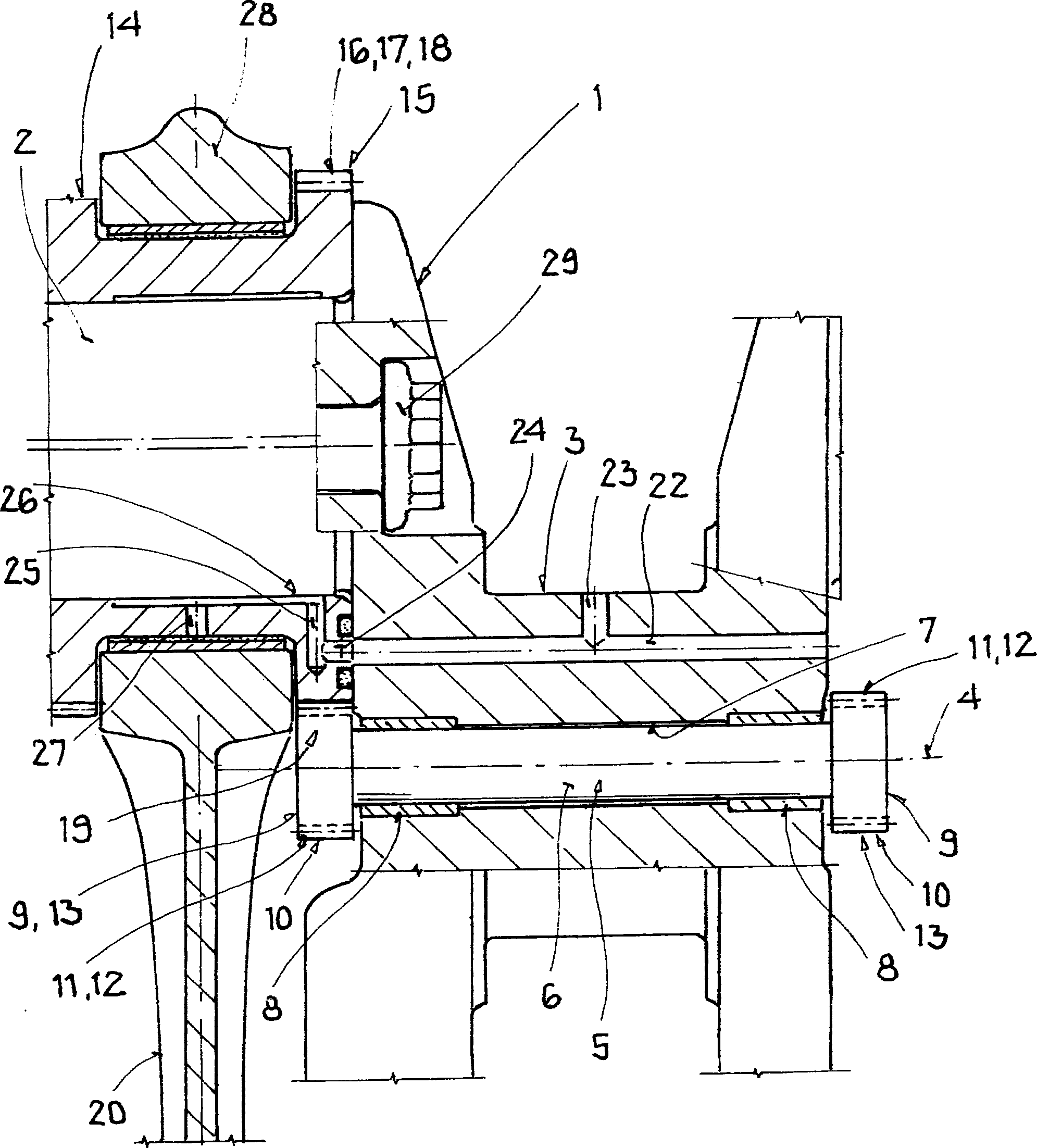
Die Erfindung betrifft eine Kurbelwelle (1), insbesondere für eine Brennkraftmaschine mit variabler Verdichtung durch Verändern eines Kurbelwellenhubs, die mindestens einen Hubzapfen (2) und mindestens einen Lagerzapfen (3) und eine Verstelleinrichtung für eine radiale Abstandseinstellung des Hubzapfens (2) zum Lagerzapfen (3) aufweist, wobei der Hubzapfen (2) mindestens eine drehbar gelagerte Pleuel-Exzenterbuchse (14) aufweist. Es ist vorgesehen, dass die Pleuel-Exzenterbuchse (14) mittels eines Drehgetriebes (19) mit einer durch den Lagerzapfen (3) führenden Drehwinkelsteuerwelle (6) wirkverbunden ist.The invention relates to a crankshaft (1), in particular for an internal combustion engine with variable compression by changing a Kurbelwellenhubs, the at least one crank pin (2) and at least one bearing pin (3) and an adjusting device for a radial distance adjustment of the crank pin (2) to the bearing journal (2). 3), wherein the crank pin (2) has at least one rotatably mounted connecting rod eccentric bushing (14). It is envisaged that the connecting rod eccentric bush (14) is operatively connected by means of a rotary gear (19) to a rotational angle control shaft (6) leading through the bearing journal (3).
Description
Die Erfindung betrifft eine Kurbelwelle, insbesondere für eine Brennkraftmaschine mit variabler Verdichtung durch Verändern eines Kurbelwellenhubs, die mindestens einen Hubzapfen und mindestens einen Lagerzapfen und eine Verstelleinrichtung für eine radiale Abstandseinstellung des Hubzapfens zum Lagerzapfen aufweist, wobei der Hubzapfen mindestens eine drehbar gelagerte Pleuel-Exzenterbuchse aufweist.The The invention relates to a crankshaft, in particular for a Internal combustion engine with variable compression by changing a Kurbelwellenhubs, the at least one crank pin and at least a journal and an adjusting device for a Radial distance adjustment of the crank pin has to journal, wherein the crank pin at least one rotatably mounted connecting rod eccentric bushing having.
Es
ist bekannt, eine Hubveränderung eines Kolbens beispielsweise
in einer Brennkraftmaschine herbeizuführen. Der Kolben
ist über eine Pleuelstange mit einer Kurbelwelle verbunden,
die eine Pleuel-Exzenterbuchse aufweist, die sich auf einem Hubzapfen
befindet. In der
Der vorliegenden Erfindung liegt daher die Aufgabe zugrunde, eine Kurbelwelle zu schaffen, die die Einstellbarkeit der Pleuel-Exzenterbuchse und damit des Hubs und der Verdichtung verbessert, um auf diesem Weg den Wirkungsgrad der Brennkraftmaschine zu erhöhen.Of the The present invention is therefore based on the object, a crankshaft to create the adjustability of the connecting rod eccentric bushing and thus the stroke and the compression improves, in this way the efficiency to increase the internal combustion engine.
Diese Aufgabe wird erfindungsgemäß dadurch gelöst, dass die Pleuel-Exzenterbuchse mittels eines Drehgetriebes mit einer durch den Lagerzapfen führenden Drehwinkelsteuerwelle wirkverbunden ist. Anders als im Stand der Technik wird die Fixierung der Pleuel-Exzenterbuchse nicht durch das Einrasten eines Befestigungsstifts an wenigen diskreten Positionen durchgeführt, sondern ein Drehgetriebe lässt eine Drehwinkeleinstellung der Pleuel-Exzenterbuchse zu. Das Drehgetriebe stellt eine Verbindung zwischen Pleuel-Exzenterbuchse und Drehwinkelsteuerwelle dar. Mit Hilfe der Drehwinkelsteuerwelle lässt sich die Pleuel-Exzenterbuchse und damit der Hub verstellen. Das Drehgetriebe ermöglicht eine kontinuierliche Verstellung der Pleuel-Exzenterbuchse, sodass eine optimale Anpassbarkeit besteht. Mit dieser Technik ist es möglich, die Verdichtung einer Brennkraftmaschine in verschiedenen Betriebszuständen zu optimieren, weil die Hubverhältnisse hochgenau eingestellt werden können. Der Wirkungsgrad der Brennkraftmaschine lässt sich auf diesem Weg erhöhen. Mittels der Drehwinkelsteuerwelle lässt sich die Drehwinkelstellung der Pleuel-Exzenterbuchse einstellen, sodass die Drehwinkelsteuerwelle ein Einstellmittel darstellt. Die Drehwinkelsteuerwelle verläuft durch den Lagerzapfen und ist vorzugsweise dort drehbar gelagert.These The object is achieved according to the invention that the connecting rod eccentric bushing by means of a rotary gear with a operatively connected by the journal guiding angle control shaft is. Unlike in the prior art, the fixation of the connecting rod eccentric bush not by the engagement of a fixing pin to a few discreet ones Positions carried out, but a rotary transmission leaves one Angle adjustment of the connecting rod eccentric bush too. The rotary gearbox provides a connection between connecting rod eccentric bushing and rotation angle control shaft dar. With the help of the rotation angle control shaft can be the Connecting rod eccentric bush and thus adjust the stroke. The rotary gearbox allows continuous adjustment of the connecting rod eccentric bush, so that an optimal adaptability exists. With this technique is it possible to compress the internal combustion engine optimize different operating conditions because the Lifting ratios can be adjusted with high accuracy. The efficiency of the internal combustion engine can be on increase this way. By means of the rotation angle control shaft leaves adjust the angular position of the connecting rod eccentric bush, so that the rotation angle control shaft constitutes an adjustment means. The Rotation angle control shaft passes through the journal and is preferably rotatably mounted there.
Eine vorteilhafte Ausgestaltung ist dadurch gekennzeichnet, dass das Drehgetriebe formschlüssig zusammenwirkende Drehelemente aufweist. Diese Art des Zusammenwirkens ist dafür verantwortlich, dass eine besonders präzise Übertragung der Bewegung durch das Drehgetriebe vorgenommen wird.A advantageous embodiment is characterized in that the Rotary gear form-locking cooperating rotary elements having. This kind of interaction is responsible for that a particularly precise transmission of the movement is made by the rotary gear.
Eine andere Fortbildung dieser Erfindung ist dadurch gekennzeichnet, dass die Drehelemente Zahnradelemente sind. Das hat zur Folge, dass kein Durchrutschen bei der zu übertragenden Bewegung stattfindet.A another embodiment of this invention is characterized that the rotary elements are gear elements. This has the consequence that no slippage takes place in the movement to be transmitted.
In einer weiteren Ausgestaltung der Erfindung ist vorgesehen, dass eines der Zahnradelemente durch eine an der Pleuel-Exzenterbuchse ausgebildete Verzahnung ausgebildet ist. Da dieses Zahnrad in das Material der Pleuel-Exzenterbuchse eingearbeitet wurde, ist sichergestellt, dass das Rad besonders stabil und formbeständig ist.In A further embodiment of the invention provides that one of the gear elements by a at the connecting rod eccentric bushing formed toothing is formed. Since this gear in the Material of the connecting rod eccentric bushing has been incorporated is ensured that the wheel is particularly stable and dimensionally stable.
In einer weiteren Ausgestaltung der Erfindung ist vorgesehen, dass eines der Zahnradelemente durch eine an der Drehwinkelsteuerwelle ausgebildete Verzahnung ausgebildet ist.In A further embodiment of the invention provides that one of the gear members through one of the rotation angle control shaft formed toothing is formed.
In einer weiteren Ausführungsform dieser Erfindung ist vorgesehen, dass die Verzahnungen der Zahnradelemente als Schrägverzahnungen ausgebildet sind. Da bei diesen Zahnradelementen Axialkräfte beim Betätigen auftreten, werden sie aneinandergepresst. Dadurch tritt praktisch kein Spiel auf. Dies führt dazu, dass die Bewegung der Drehwinkelsteuerwelle sehr präzise auf die jeweilige Pleuel-Exzenterbuchse übertragen wird.In a further embodiment of this invention is provided that the teeth of the gear elements as helical gears are formed. Because with these gear elements axial forces when pressed, they are pressed together. As a result, virtually no play occurs. This leads to, that the movement of the rotation angle control shaft very precise is transferred to the respective connecting rod eccentric bushing.
In einer weiteren, bevorzugten Ausführungsform sieht die Ausgestaltung der Erfindung vor, dass die Drehwinkelsteuerwelle mehrere Drehwinkelsteuerwellenabschnitte aufweist. Diese Konstruktionsweise erlaubt es, die vorliegende Erfindung bei Kurbelwellen mit mehreren Hubzapfen anzuwenden.In Another preferred embodiment provides the embodiment According to the invention, the rotation angle control shaft includes a plurality of rotation angle control shaft sections having. This construction allows the present invention to be used with crankshafts with several crank pins.
Eine andere positive Weiterentwicklung dieser Erfindung sieht vor, dass mindestens einige der Drehwinkelsteuerwellenabschnitte zwei Schrägverzahnungen aufweisen, die jeweils gegenläufig zueinander gerichtet sind. Aufgrund der gegenläufigen Schrägverzahnungen werden die Drehwinkelsteuerwellenabschnitte durch das Auftreten gegenläufiger axialer Kräfte nicht verschoben.A Another positive development of this invention provides that at least some of the rotational control shaft sections have two helical gears have, each directed in opposite directions are. Due to the opposite helical gears the rotation angle control shaft sections are caused by the occurrence opposite axial forces not shifted.
In einer weiteren Ausführungsform ist vorgesehen, dass die Schrägverzahnungen der Drehwinkelsteuerwellenabschnitte an einem Ende des jeweiligen Drehwinkelsteuerwellenabschnitts eingearbeitet und am anderen Ende des jeweiligen Drehwinkelsteuerwellenabschnitts als Ritzel aufgeschrumpft sind. Durch diese Fertigungsweise wird eine erhöhte Flexibilität bei der Montage erreicht.In a further embodiment, it is provided that the helical gears of the Drehwin Kelsteuerwellenabschnitte are incorporated at one end of the respective Drehwinkelsteuerwellenabschnitts and shrunk at the other end of the respective rotation angle control shaft portion as a pinion. By this manufacturing method increased flexibility during assembly is achieved.
In einer anderen Ausführungsform ist vorgesehen, dass die Drehwinkelsteuerwelle parallel zu einer Kurbelwellenachse verläuft. Diese Anordnung ermöglicht ein präzises Kämmen der Zahnradelemente der Drehwinkelsteuerwelle und der Pleuel-Exzenterbuchse.In another embodiment provides that the Rotation angle control shaft is parallel to a crankshaft axis. This arrangement allows precise combing the gear elements of the rotation angle control shaft and the connecting rod eccentric bushing.
In einer anderen Ausführungsform ist vorgesehen, dass die Kurbelwelle für mehrere Zylinder der Brennkraftmaschine Pleuel-Exzenterbuchsen und mehrere Drehwinkelsteuerwellenabschnitte aufweist. Diese Konstruktionsweise erlaubt es, die Erfindung bei Kurbelwellen mit mehreren Hubzapfen anzuwenden.In another embodiment provides that the Crankshaft for several cylinders of the internal combustion engine Connecting rod eccentric bushes and a plurality of rotational angle control shaft sections having. This construction allows the invention to be incorporated Use crankshafts with multiple crank pins.
In einer weiteren Ausführungsform ist vorgesehen, dass mindestens einige der Drehwinkelsteuerwellenabschnitte und mindestens einige der Pleuel-Exzenterbuchsen jeweils mindestens zwei Verzahnungen derart aufweisen, dass mehrere Drehwinkelsteuerwellenabschnitte und Pleuel-Exzenterbuchsen zur Ausbildung eines drehbar miteinander gekoppelten Stranges in Reihe geschaltet sind. Diese Konstruktionsweise erlaubt es, einen durchgängigen Antriebsstrang für die Pleuel-Exzenterbuchsen zu schaffen. Eine bevorzugte Ausführungsform sieht vor, dass die Reihenschaltung in abwechselnder Folge hintereinander geschaltete Drehwinkelsteuerwellenabschnitte und Pleuel-Exzenterbuchsen aufweist.In A further embodiment provides that at least some of the rotational angle control shaft sections and at least some the connecting rod eccentric bushes at least two gears such that a plurality of rotational angle control shaft sections and connecting rod eccentric bushings for forming a rotatable with each other coupled strands are connected in series. This construction method allows a continuous powertrain for to create the connecting rod eccentric bushes. A preferred embodiment provides that the series connection in alternating sequence one behind the other switched Drehwinkelsteuerwellenabschnitte and connecting rod eccentric bushings having.
Eine weitere bevorzugte Ausführungsform sieht vor, dass die Drehwinkelsteuerwelle eine Antriebseinheit besitzt. Mit dieser Antriebseinheit ist über die Drehwinkelsteuerwelle eine Drehwinkeleinstellung der mindestens einen Pleuel-Exzenterbuchse möglich.A Another preferred embodiment provides that the Angular control shaft has a drive unit. With this drive unit is a rotation angle adjustment via the rotation angle control shaft the at least one connecting rod eccentric bush possible.
Eine weitere Ausführungsform sieht vor, dass die Antriebseinheit ein insbesondere elektromechanisch oder hydraulisch angetriebenes Planetenradgetriebe ist.A Another embodiment provides that the drive unit a particular electromechanically or hydraulically driven Planetary gear is.
Eine weitere Ausführungsform der Erfindung sieht vor, dass die Kurbelwelle eine zusammengebaute Kurbelwelle ist. Diese Fertigungsweise erlaubt ein Gießen oder Schmieden der Kurbelwelle als Ganzes und ein anschließendes Teilen, insbesondere Zersägen. Bevorzugt erfolgt ein Gießen oder Schmieden der Hubzapfen mit Übermaß. Die Hubzapfen werden anschließend geteilt und erhalten eine Hirth-Verzahnung. Nach dem Verschrauben der Einzelteile der Kurbelwelle werden die Hubzapfen bearbeitet und erhalten dadurch ihren Solldurchmesser.A Another embodiment of the invention provides that the Crankshaft is an assembled crankshaft. This production method allows casting or forging the crankshaft as a whole and subsequent parts, in particular sawing. Preferably, casting or forging of the crank pin takes place with excess. The crank pins are subsequently divided and receive a Hirth gearing. After screwing the crankshaft components are handled by the crank pins and thereby obtain their nominal diameter.
Die Erfindung wird nachfolgend anhand eines Ausführungsbeispiels näher beschrieben. Es zeigen:The Invention will be described below with reference to an embodiment described in more detail. Show it:
Die
Auf
dem Hubzapfen
Auf
der Pleuel-Exzenterbuchse
Für
die nachfolgende Funktionserklärung wird zunächst
nur Von einem Drehwinkelsteuerwellenabschnitt
Vorzugsweise
sind sämtliche Drehwinkelsteuerwellenabschnitte
Bevorzugt
wird die Kurbelwelle
Die
Der
Antrieb
Aufgrund
der Erfindung wird deutlich, dass sich die Verdichtung der Brennkraftmaschine
durch Einstellung des Hubs kontinuierlich verändern lässt, sodass
in jeder Betriebssituation der geeignete Hub stufenlos, das heißt
kontinuierlich, eingestellt werden kann. Aufgrund der Ausbildung
der Verzahnungen
- 11
- Kurbelwellecrankshaft
- 22
- Hubzapfencrank pins
- 33
- Lagerzapfenpivot
- 44
- Längsachselongitudinal axis
- 55
- DrehwinkelsteuerwellenabschnittRotation angle control shaft section
- 66
- DrehwinkelsteuerwelleRotation angle control shaft
- 77
- Bohrungdrilling
- 88th
- Lagerbuchsebearing bush
- 99
- Drehelementrotating member
- 1010
- Zahnradelementgear member
- 1111
- Verzahnunggearing
- 1212
- Schrägverzahnunghelical teeth
- 1313
- Ritzelpinion
- 1414
- Pleuel-ExzenterbuchseConnecting rod eccentric
- 1515
- Drehelementrotating member
- 1616
- Zahnradelementgear member
- 1717
- Verzahnunggearing
- 1818
- Schrägverzahnunghelical teeth
- 1919
- Drehgetrieberotary gear
- 2020
- Pleuelpleuel
- 2121
- Antriebdrive
- 2222
- Schmiermittelkanallubricant channel
- 2323
- Radialbohrungradial bore
- 2424
- Stichbohrungbranch bore
- 2525
- Stichbohrungbranch bore
- 2626
- Lagerbereichstorage area
- 2727
- Schmiermittelbohrunglubricant bore
- 2828
- Pleuelaugeconnecting rod
- 2929
- Verschraubungscrew
- 3030
- Schwingungsdämpfervibration
- 3131
- Planetenradgetriebeplanetary gear
- 3232
- Zahnradgear
ZITATE ENTHALTEN IN DER BESCHREIBUNGQUOTES INCLUDE IN THE DESCRIPTION
Diese Liste der vom Anmelder aufgeführten Dokumente wurde automatisiert erzeugt und ist ausschließlich zur besseren Information des Lesers aufgenommen. Die Liste ist nicht Bestandteil der deutschen Patent- bzw. Gebrauchsmusteranmeldung. Das DPMA übernimmt keinerlei Haftung für etwaige Fehler oder Auslassungen.This list The documents listed by the applicant have been automated generated and is solely for better information recorded by the reader. The list is not part of the German Patent or utility model application. The DPMA takes over no liability for any errors or omissions.
Zitierte PatentliteraturCited patent literature
- - DE 10309652 A1 [0002] - DE 10309652 A1 [0002]
Claims (16)
Priority Applications (1)
| Application Number | Priority Date | Filing Date | Title |
|---|---|---|---|
| DE102008009869A DE102008009869A1 (en) | 2008-02-19 | 2008-02-19 | Crank shaft, particularly for internal combustion engine, has crank shaft stroke, which has stroke plug, journal plug and adjusting device for distance adjustment of stroke plug for journal plug |
Applications Claiming Priority (1)
| Application Number | Priority Date | Filing Date | Title |
|---|---|---|---|
| DE102008009869A DE102008009869A1 (en) | 2008-02-19 | 2008-02-19 | Crank shaft, particularly for internal combustion engine, has crank shaft stroke, which has stroke plug, journal plug and adjusting device for distance adjustment of stroke plug for journal plug |
Publications (1)
| Publication Number | Publication Date |
|---|---|
| DE102008009869A1 true DE102008009869A1 (en) | 2009-08-20 |
Family
ID=40874106
Family Applications (1)
| Application Number | Title | Priority Date | Filing Date |
|---|---|---|---|
| DE102008009869A Withdrawn DE102008009869A1 (en) | 2008-02-19 | 2008-02-19 | Crank shaft, particularly for internal combustion engine, has crank shaft stroke, which has stroke plug, journal plug and adjusting device for distance adjustment of stroke plug for journal plug |
Country Status (1)
| Country | Link |
|---|---|
| DE (1) | DE102008009869A1 (en) |
Cited By (6)
| Publication number | Priority date | Publication date | Assignee | Title |
|---|---|---|---|---|
| DE102011110908A1 (en) * | 2011-08-18 | 2013-02-21 | GM Global Technology Operations LLC (n. d. Gesetzen des Staates Delaware) | Crank mechanism for converting linear motion into rotary motion or vice versa, has lever arm which is displaced radially from crankshaft axis by one connecting rod pivotally connected to another connecting rod |
| WO2016174321A1 (en) * | 2015-04-28 | 2016-11-03 | Peugeot Citroen Automobiles Sa | System for varying the compression ratio of an internal combustion engine provided with a liquid lubricant guiding element |
| FR3053734A1 (en) * | 2016-07-05 | 2018-01-12 | Peugeot Citroen Automobiles Sa | DEVICE FOR LUBRICATING AND / OR COOLING A CONFINED CHAMBER OF A CRANKSHAFT OF AN INTERNAL COMBUSTION ENGINE |
| CN112502828A (en) * | 2020-02-24 | 2021-03-16 | 长城汽车股份有限公司 | Variable compression ratio drive structure |
| DE102014216460B4 (en) | 2014-08-19 | 2022-02-24 | Bayerische Motoren Werke Aktiengesellschaft | spur gear |
| EP4159989A3 (en) * | 2021-09-30 | 2023-04-19 | Honda Motor Co., Ltd. | Variable compression-ratio device |
Citations (7)
| Publication number | Priority date | Publication date | Assignee | Title |
|---|---|---|---|---|
| FR590967A (en) * | 1924-08-18 | 1925-06-26 | Moteurs Guerbilsky Claude Zenz | Motion transmission system for variable stroke motors |
| DE1864599U (en) * | 1959-11-14 | 1962-12-27 | Schuler L Ag | CRANKSET OR ECCENTRIC DRIVE FOR A SLIDE IN PRESSES, PUNCHING OR. DGL. |
| US4887560A (en) * | 1988-06-20 | 1989-12-19 | Heniges William B | Crankshaft assembly for variable stroke engine for variable compression |
| DE3936649A1 (en) * | 1989-11-03 | 1991-05-08 | Ingelheim Peter Graf Von | Crankshaft giving adjustable stroke - has drive to adjusting components from one end via components rotating with it |
| EP1247958A1 (en) * | 2001-04-07 | 2002-10-09 | Ford Global Technologies, Inc., A subsidiary of Ford Motor Company | Combuistion engine with variable compression ratio |
| DE10309852A1 (en) * | 2002-03-14 | 2003-10-09 | Skf Ind Spa | Seal system for roller bearing comprises two cover plate, first plate carrying encoder which fits into channel and second plate carrying sealing lip which rests against lateral surface on first plate |
| DE10309652A1 (en) | 2003-03-06 | 2004-09-23 | Daimlerchrysler Ag | Internal combustion engine for e.g. motor vehicle, has locking device used to securely latch to eccentric cam to prevent eccentric cam from rotating if desired |
-
2008
- 2008-02-19 DE DE102008009869A patent/DE102008009869A1/en not_active Withdrawn
Patent Citations (7)
| Publication number | Priority date | Publication date | Assignee | Title |
|---|---|---|---|---|
| FR590967A (en) * | 1924-08-18 | 1925-06-26 | Moteurs Guerbilsky Claude Zenz | Motion transmission system for variable stroke motors |
| DE1864599U (en) * | 1959-11-14 | 1962-12-27 | Schuler L Ag | CRANKSET OR ECCENTRIC DRIVE FOR A SLIDE IN PRESSES, PUNCHING OR. DGL. |
| US4887560A (en) * | 1988-06-20 | 1989-12-19 | Heniges William B | Crankshaft assembly for variable stroke engine for variable compression |
| DE3936649A1 (en) * | 1989-11-03 | 1991-05-08 | Ingelheim Peter Graf Von | Crankshaft giving adjustable stroke - has drive to adjusting components from one end via components rotating with it |
| EP1247958A1 (en) * | 2001-04-07 | 2002-10-09 | Ford Global Technologies, Inc., A subsidiary of Ford Motor Company | Combuistion engine with variable compression ratio |
| DE10309852A1 (en) * | 2002-03-14 | 2003-10-09 | Skf Ind Spa | Seal system for roller bearing comprises two cover plate, first plate carrying encoder which fits into channel and second plate carrying sealing lip which rests against lateral surface on first plate |
| DE10309652A1 (en) | 2003-03-06 | 2004-09-23 | Daimlerchrysler Ag | Internal combustion engine for e.g. motor vehicle, has locking device used to securely latch to eccentric cam to prevent eccentric cam from rotating if desired |
Cited By (8)
| Publication number | Priority date | Publication date | Assignee | Title |
|---|---|---|---|---|
| DE102011110908A1 (en) * | 2011-08-18 | 2013-02-21 | GM Global Technology Operations LLC (n. d. Gesetzen des Staates Delaware) | Crank mechanism for converting linear motion into rotary motion or vice versa, has lever arm which is displaced radially from crankshaft axis by one connecting rod pivotally connected to another connecting rod |
| DE102014216460B4 (en) | 2014-08-19 | 2022-02-24 | Bayerische Motoren Werke Aktiengesellschaft | spur gear |
| WO2016174321A1 (en) * | 2015-04-28 | 2016-11-03 | Peugeot Citroen Automobiles Sa | System for varying the compression ratio of an internal combustion engine provided with a liquid lubricant guiding element |
| FR3035680A1 (en) * | 2015-04-28 | 2016-11-04 | Peugeot Citroen Automobiles Sa | SYSTEM FOR VARYING THE COMPRESSION RATE OF AN INTERNAL COMBUSTION ENGINE PROVIDED WITH A LUBRICATING LIQUID GUIDE ELEMENT |
| FR3053734A1 (en) * | 2016-07-05 | 2018-01-12 | Peugeot Citroen Automobiles Sa | DEVICE FOR LUBRICATING AND / OR COOLING A CONFINED CHAMBER OF A CRANKSHAFT OF AN INTERNAL COMBUSTION ENGINE |
| CN112502828A (en) * | 2020-02-24 | 2021-03-16 | 长城汽车股份有限公司 | Variable compression ratio drive structure |
| CN112502828B (en) * | 2020-02-24 | 2022-01-28 | 长城汽车股份有限公司 | Variable compression ratio drive structure |
| EP4159989A3 (en) * | 2021-09-30 | 2023-04-19 | Honda Motor Co., Ltd. | Variable compression-ratio device |
Similar Documents
| Publication | Publication Date | Title |
|---|---|---|
| DE10051271B4 (en) | In their compression ratio adjustable piston internal combustion engine with integrated Verstellaktuator | |
| DE102009013996A1 (en) | Device for adjusting the eccentricity for a crank-CVT transmission | |
| DE102007017897A1 (en) | Adjustable camshaft | |
| DE102008009869A1 (en) | Crank shaft, particularly for internal combustion engine, has crank shaft stroke, which has stroke plug, journal plug and adjusting device for distance adjustment of stroke plug for journal plug | |
| DE102008058629A1 (en) | Balance shaft unit | |
| DE19939210A1 (en) | Coupling element for connecting two axially parallel shafts arranged one behind the other with a transverse spacing | |
| DE102012001648B4 (en) | Multi-joint crank drive of an internal combustion engine and method for assembling a multi-link crank drive | |
| DE102004041751B4 (en) | Camshaft adjuster with a coupling between an actuating shaft and an adjusting gear | |
| DE102008046821B4 (en) | Crankshaft for a variable compression internal combustion engine and variable compression internal combustion engine | |
| DE102004058551B4 (en) | transmission | |
| DE19624074A1 (en) | Drive gears with eccentric shaft esp. for balance shafts in IC engines | |
| EP1079086B1 (en) | Internal combustion engine with an electric machine auxiliary drive | |
| DE19501561A1 (en) | Linear reciprocal motion converter into rotary motion for IC engines etc | |
| DE102016203074B3 (en) | gearmotor | |
| EP3267011A1 (en) | Device for changing a compression ratio of a reciprocating piston combustion engine | |
| EP1803904A2 (en) | Camshaft | |
| DE3114459A1 (en) | Crank gear for a reciprocating piston engine | |
| DE102020110793A1 (en) | Crankshaft with oil supply | |
| DE102019213717A1 (en) | Switching device, transmission with such and harvesting machine | |
| WO1988004356A1 (en) | Crank mechanism, in particular for alternating piston engines | |
| DE102004041769A1 (en) | Camshaft adjusting device for adjusting the relative angle of a camshaft to a crankshaft of an I.C. engine transfers the driving torque via a coupling star of a first coupling half | |
| WO2000057073A1 (en) | Coupling element for connecting two shafts which are parallel to an axis and arranged behind each other on the same axis with a cross-distance therebetween | |
| EP2638256B1 (en) | Camshaft adjuster for an internal combustion engine | |
| WO2006058743A1 (en) | Gear mechanism | |
| DE4430423A1 (en) | Transmission arrangement |
Legal Events
| Date | Code | Title | Description |
|---|---|---|---|
| OM8 | Search report available as to paragraph 43 lit. 1 sentence 1 patent law | ||
| 8130 | Withdrawal |