EP2638256B1 - Camshaft adjuster for an internal combustion engine - Google Patents
Camshaft adjuster for an internal combustion engine Download PDFInfo
- Publication number
- EP2638256B1 EP2638256B1 EP11748378.4A EP11748378A EP2638256B1 EP 2638256 B1 EP2638256 B1 EP 2638256B1 EP 11748378 A EP11748378 A EP 11748378A EP 2638256 B1 EP2638256 B1 EP 2638256B1
- Authority
- EP
- European Patent Office
- Prior art keywords
- adapter
- camshaft
- output gear
- gear
- camshaft adjuster
- Prior art date
- Legal status (The legal status is an assumption and is not a legal conclusion. Google has not performed a legal analysis and makes no representation as to the accuracy of the status listed.)
- Not-in-force
Links
Images

Classifications
-
- F—MECHANICAL ENGINEERING; LIGHTING; HEATING; WEAPONS; BLASTING
- F01—MACHINES OR ENGINES IN GENERAL; ENGINE PLANTS IN GENERAL; STEAM ENGINES
- F01L—CYCLICALLY OPERATING VALVES FOR MACHINES OR ENGINES
- F01L1/00—Valve-gear or valve arrangements, e.g. lift-valve gear
- F01L1/34—Valve-gear or valve arrangements, e.g. lift-valve gear characterised by the provision of means for changing the timing of the valves without changing the duration of opening and without affecting the magnitude of the valve lift
- F01L1/344—Valve-gear or valve arrangements, e.g. lift-valve gear characterised by the provision of means for changing the timing of the valves without changing the duration of opening and without affecting the magnitude of the valve lift changing the angular relationship between crankshaft and camshaft, e.g. using helicoidal gear
- F01L1/352—Valve-gear or valve arrangements, e.g. lift-valve gear characterised by the provision of means for changing the timing of the valves without changing the duration of opening and without affecting the magnitude of the valve lift changing the angular relationship between crankshaft and camshaft, e.g. using helicoidal gear using bevel or epicyclic gear
-
- F—MECHANICAL ENGINEERING; LIGHTING; HEATING; WEAPONS; BLASTING
- F01—MACHINES OR ENGINES IN GENERAL; ENGINE PLANTS IN GENERAL; STEAM ENGINES
- F01L—CYCLICALLY OPERATING VALVES FOR MACHINES OR ENGINES
- F01L1/00—Valve-gear or valve arrangements, e.g. lift-valve gear
- F01L1/34—Valve-gear or valve arrangements, e.g. lift-valve gear characterised by the provision of means for changing the timing of the valves without changing the duration of opening and without affecting the magnitude of the valve lift
-
- F—MECHANICAL ENGINEERING; LIGHTING; HEATING; WEAPONS; BLASTING
- F02—COMBUSTION ENGINES; HOT-GAS OR COMBUSTION-PRODUCT ENGINE PLANTS
- F02F—CYLINDERS, PISTONS OR CASINGS, FOR COMBUSTION ENGINES; ARRANGEMENTS OF SEALINGS IN COMBUSTION ENGINES
- F02F1/00—Cylinders; Cylinder heads
- F02F1/24—Cylinder heads
-
- F—MECHANICAL ENGINEERING; LIGHTING; HEATING; WEAPONS; BLASTING
- F16—ENGINEERING ELEMENTS AND UNITS; GENERAL MEASURES FOR PRODUCING AND MAINTAINING EFFECTIVE FUNCTIONING OF MACHINES OR INSTALLATIONS; THERMAL INSULATION IN GENERAL
- F16H—GEARING
- F16H1/00—Toothed gearings for conveying rotary motion
- F16H1/02—Toothed gearings for conveying rotary motion without gears having orbital motion
- F16H1/04—Toothed gearings for conveying rotary motion without gears having orbital motion involving only two intermeshing members
- F16H1/06—Toothed gearings for conveying rotary motion without gears having orbital motion involving only two intermeshing members with parallel axes
- F16H1/10—Toothed gearings for conveying rotary motion without gears having orbital motion involving only two intermeshing members with parallel axes one of the members being internally toothed
-
- F—MECHANICAL ENGINEERING; LIGHTING; HEATING; WEAPONS; BLASTING
- F16—ENGINEERING ELEMENTS AND UNITS; GENERAL MEASURES FOR PRODUCING AND MAINTAINING EFFECTIVE FUNCTIONING OF MACHINES OR INSTALLATIONS; THERMAL INSULATION IN GENERAL
- F16H—GEARING
- F16H1/00—Toothed gearings for conveying rotary motion
- F16H1/28—Toothed gearings for conveying rotary motion with gears having orbital motion
- F16H1/36—Toothed gearings for conveying rotary motion with gears having orbital motion with two central gears coupled by intermeshing orbital gears
-
- F—MECHANICAL ENGINEERING; LIGHTING; HEATING; WEAPONS; BLASTING
- F16—ENGINEERING ELEMENTS AND UNITS; GENERAL MEASURES FOR PRODUCING AND MAINTAINING EFFECTIVE FUNCTIONING OF MACHINES OR INSTALLATIONS; THERMAL INSULATION IN GENERAL
- F16H—GEARING
- F16H57/00—General details of gearing
- F16H57/02—Gearboxes; Mounting gearing therein
-
- F—MECHANICAL ENGINEERING; LIGHTING; HEATING; WEAPONS; BLASTING
- F16—ENGINEERING ELEMENTS AND UNITS; GENERAL MEASURES FOR PRODUCING AND MAINTAINING EFFECTIVE FUNCTIONING OF MACHINES OR INSTALLATIONS; THERMAL INSULATION IN GENERAL
- F16H—GEARING
- F16H57/00—General details of gearing
- F16H57/04—Features relating to lubrication or cooling or heating
Definitions
- the invention relates to a camshaft adjuster for an internal combustion engine, comprising a rotatably connectable to a crankshaft drive wheel, a relatively rotatable about a rotation axis arranged internally toothed driven wheel, and an adapter which is arranged on the inner circumference of the driven gear and the output shaft rotatably with a Camshaft is connectable.
- a camshaft adjuster is used for the targeted adjustment of the phase position between a camshaft and a crankshaft in an internal combustion engine and thus enables the optimized setting of the valve timing over the engine load and the engine speed. Thus, a significant reduction in fuel consumption and exhaust emissions and an increase in engine performance can be achieved.
- the camshaft adjusting device or the camshaft adjuster comprises a drive wheel and a driven wheel, which are arranged rotatable relative to one another.
- the drive wheel is for this purpose designed as a ring gear, in which the output gear is inserted.
- the output gear is formed on its inner circumference with an internal toothing and with an internal toothing adjacent annular receiving portion.
- the receiving portion serves to receive and position an adapter, via which the output gear is non-rotatably connected to a camshaft.
- the adapter is inserted into the output gear and welded there rotatably within the receiving portion.
- a camshaft adjuster for an internal combustion engine comprising one with a crankshaft rotatably connectable drive wheel, a relative to this about a rotation axis rotatably mounted, internally toothed output gear, and an adapter which is arranged on the inner circumference of the driven gear and via the output gear rotatably connected to a camshaft. It is provided that the adapter is attached via the internal toothing on the inner circumference of the driven gear.
- the invention takes into account that the trouble-free operation of a camshaft adjuster, the reliable torque transmission between the drive and output must be guaranteed.
- electromechanical camshaft adjusters usually a drive wheel is mounted on a driven wheel, which in turn is connected by means of an adapter with a camshaft.
- the adapter itself is in this case typically arranged within the output gear on the inner circumference, for which purpose a separately provided for this purpose exception section is provided on the inner circumference so far. This is not desirable in view of the associated with the production effort and the associated costs.
- the invention recognizes that this problem is surprisingly overcome by an attachment of the adapter via the internal toothing of the driven gear on its inner circumference.
- the hitherto necessary additional processing of the inner circumference of the output gear for fastening the adapter can be omitted.
- the adapter can be arranged on the driven wheel, without the introduction of a specially provided for receiving portion on the inner circumference of the driven wheel is necessary.
- the drive wheel is in particular designed as a ring gear and has an internal toothing, which may be formed partially or continuously on the inner circumference.
- the drive of the drive wheel is achieved via the rotationally fixed connection with a crankshaft.
- the drive wheel may be formed, for example, as a sprocket, wherein the rotationally fixed connection is achieved with the crankshaft via a chain.
- the output gear may also be designed as a pulley and be driven accordingly via a belt drive.
- the output gear On the inner circumference of the drive wheel, the output gear is usually arranged, wherein the drive wheel can be mounted on the output gear.
- the output gear is preferably also designed as a ring gear and has an internal toothing.
- the internal teeth are introduced in the manufacture of the output gear by means of a so-called Räumreaes in the inner circumference.
- a broach with a corresponding contour is pulled or pushed through an already introduced in the driven gear hole.
- the cross section of the broach here corresponds to the contour of the formed after the broaching process on the inner circumference of the driven gear internal teeth.
- the internal teeth can form an adjusting gear in the installed state together with the internal teeth of a driven gear, which can be driven for example via a spur gear of a shaft gear.
- only a part of the internal toothing of the output gear is then available, since the adapter is arranged in the mounted state on the inner circumference of the output gear.
- the adapter For positioning of the adapter, this is expediently formed with an outer diameter which is matched to the inner diameter of the driven gear.
- the adapter may be formed with a circular cross-section.
- the adapter can be inserted into the output gear and fixed there, so that it comes with its outer circumference on the inner circumference of the driven gear, or at the local internal teeth to the plant.
- the adapter with a counter toothing is formed, which engages in the internal toothing of the driven gear and the adapter so positioned.
- the adapter may be formed, for example, as a substantially flat end cover. It is preferably formed with a central bore through which a central screw for fastening the individual components of a camshaft adjuster can be passed to each other.
- the adapter can be screwed into the bore on the end face of the camshaft via the fastening of the central screw.
- the adapter can furthermore have recesses into which fastening elements formed on a front end of the camshaft can engage.
- the adapter is pressed onto the tip circle of the internal toothing of the driven gear.
- the tip diameter in gears typically refers to the outside diameter of the tooth circle, that is, the diameter given by the ends of the teeth.
- the pressing of the adapter on the top circle allows its simple arrangement on the inner circumference of the driven gear, since the receiving portion or the press-in portion is provided by the already existing internal toothing available.
- the insertion diameter of the press-in section for the adapter thus corresponds to the tip circle diameter of the internal toothing.
- a processing of the press-in can be omitted.
- the outer diameter of the adapter is in this case approximately the same size as that of the head circle diameter of the driven gear.
- connection produced by the pressing in principle can be either of solid or movable form.
- the connection points between the tooth ends and the outer circumference of the adapter can be transmitted.
- Furthermore remain when pressing the adapter on the tip circle of the internal teeth free spaces between the Teeth and the outer circumference of the adapter. These tooth clearances can be used for lubrication of the teeth.
- the internal toothing is formed axially continuously on the driven wheel.
- the continuous geometry of the internal toothing allows easy production or introduction of the internal toothing on the inner circumference of the driven wheel. Since a separate receiving section or press-fit paragraph for the adapter is not necessary, resulting in the inner circumference of an enlarged clearing length in the introduction of the internal teeth. This ensures a secure guidance of the broach used.
- the supporting portion of the internal toothing is increased by the continuous formation of the internal toothing, resulting in, for example, an extension of the life. Since the internal toothing is formed on the entire inner circumference of the output gear, is correspondingly the gear outlet in the mounted state axially end behind the adapter.
- the adapter is welded to the output gear, resulting in a secure connection of the two components results.
- the adapter and the driven gear are welded segmentally, in particular at the contact points between the tooth ends and the outer circumference of the adapter, so that the tooth clearances are available even after welding for lubricant.
- a laser welding which due to high welding speed, a narrow weld form and a low thermal distortion allows the required precision when connecting the components.
- the adapter is designed as a cover. Due to the design as a cover cover of the adapter in the installed state in addition to the torque transmission between a camshaft and a crankshaft, the adjusting gear on the camshaft axially facing side complete.
- the camshaft adjuster is thus protected, for example against external influences such as impurities or against leaks.
- the drive wheel is designed as a ring gear and mounted on the output gear.
- a sliding bearing is particularly suitable in which the two components which move relative to one another are in direct contact with one another. They slide against each other against the resistance caused by the sliding friction. This resistance can be reduced for example by the choice of low-friction material pairings or by lubrication.
- a slide bearing is particularly suitable, since in this case no additional space must be provided.
- a stop component for the camshaft is included, which is axially counterposed to the drive wheel.
- the stop component is designed as a stop ring with a stop surface for a camshaft.
- the abutment surface may for example be formed with a projection into which a recess on the end face of the camshaft can engage.
- a stop surface may be provided on the output gear itself.
- a rotational angle limiting between the drive wheel and the output shaft rotatably connected to the camshaft by means of the adapter is achieved by the stop surface.
- the stop component and the drive wheel are preferably at least partially, ie in particular in the area of the counter bearing, welded together.
- the stop component is rotatably connected to the drive wheel.
- other attachment options such as caulking or screwing conceivable.
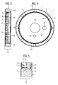
- Fig. 1 shows a driven wheel 1 in a three-dimensional representation.
- the output gear 1 is annularly formed as a ring gear and has on its inner circumference 3 an internal toothing 5.
- an adapter can be attached to the driven wheel 1 in the mounted state. A detailed description can be found in the Fig. 3 to 6 ,
- the internal toothing 5 is formed both axially continuous on the inner circumference 3 of the output gear 1 and circumferentially on the entire inner circumference 3. This results in a continuous geometry, which makes it possible to introduce the internal toothing 5 in a simple manner by means of a broaching process in the inner circumference 3 of the driven wheel 1. Since a separate receiving portion for an adapter is not necessary, the production of the internal teeth 5 is facilitated. It results in the inner circumference 3 an enlarged reaming length, which allows a secure guidance of the broach used for evacuation.
- a broaching needle with a corresponding contour is drawn through a bore in the driven gear 1 to bring in the internal toothing 5.
- the broach here has a cross section which corresponds to the contour of the internal teeth 5 of the driven wheel 1, which are formed after broaching on the inner circumference 3.
- the internal teeth 5 formed after broaching consist of a number of teeth 7 adjacent to each other along the circumference.
- the ends 9 of the teeth 7 extending inwardly radially from the output gear 1 define the diameter of the tip circle 11 of the internal toothing 5.
- the teeth 7 extend in the output gear 1 from the inner circumference 3 of all equally far radially inward.
- Fig. 2 is the output gear according to Fig. 1 shown in a longitudinal section. Based on this representation, the axially continuous, so formed over the entire axial width 12 of the driven gear 1 internal teeth 5 is clearly visible. This embodiment is possible since no separate receiving section is necessary for attaching or fastening an adapter.
- the outer diameter in the area provided for fastening for an adapter thus corresponds to the diameter of the tip circle 11 of the internal toothing 5. A broach used for introducing the internal toothing 5 is thus securely guided over the entire axial width 12 of the driven wheel 1.
- Fig. 3 is the output gear 1 according to Fig. 1 to see with an adapter 13 in a longitudinal section.
- the adapter 13 is formed as a flat circular end cover and fixed on the inner toothing 5 on the inner circumference 3 of the driven wheel 1.
- the outer diameter 14 of the adapter 13 is approximately the same size as the diameter of the tip circle 11 of the driven wheel 1.
- the adapter 13 After evacuation of the driven gear 1, the adapter 13 is pressed onto the tip circle 11 of the internal toothing 5.
- the two components are rotatably connected to each other.
- the welding takes place here at the points at which the radially inwardly extending ends 9 of the teeth 7 contact the outer circumference 14 of the adapter 13.
- Fig. 4 shows a plan view of the driven wheel 1 with the adapter 13 according to Fig. 3 in which the tooth clearances 17 between the teeth 7 and the outer circumference of the adapter 13 are clearly visible.
- the adapter 13 itself can be made due to the omission of a separate press-in with an outer diameter which corresponds approximately to the diameter of the top circle 11 of the internal gear 5 of the driven gear 1. As a result, material can be saved in the manufacture of the adapter 13.
- a central bore 19 is formed through which a central screw can be passed for mounting. This central screw can then be mounted in a thread on the front side of a camshaft. In this way, the adapter 13 can be screwed against rotation with a camshaft.
- the adapter 13 with two through holes 21, 23 is formed, which serve in the installed state of the lubricant supply of the camshaft adjuster or the variable speed.
- Fig. 5 is a detailed view of the welded to the driven part 1 adapter 13 Fig. 3 to see. Based on this detailed view it can be seen that due to the continuous design of the supporting portion of the internal toothing 5 is particularly high. Since the internal toothing 5 is formed on the entire inner circumference 3 of the driven wheel 1, the toothed wheel outlet 25 in the assembled state lies axially end behind the adapter 13 pressed onto the head circle 11.
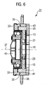
- Fig. 6 is a camshaft adjusting device 31 for an internal combustion engine with the driven wheel 1 and the adapter 13 according to the Fig. 3 to 5 shown in a longitudinal section. Because in the Fig. 1 to 5 both the output gear 1 and the adapter 13 have already been described in detail, reference is made to this point.
- the camshaft adjuster 31 has a drive wheel 33, which, like the Abtreibsteil 1 is formed as a ring gear.
- the drive wheel 33 is mounted on the output gear 1 via a plain bearing 35.
- the two components are arranged rotatable relative to each other about a common axis of rotation 37.
- the drive of the camshaft adjuster 31 takes place in operation via the drive wheel 33 and a crankshaft, not shown.
- the drive wheel 33 is designed for this purpose as a sprocket 38 and can be rotatably connected via a chain with a crankshaft.
- the torque is transmitted via an adjusting motor, not shown, to the drive wheel 33 and the output gear 1 and thus transmit the camshaft. In this way, a targeted adjustment of the phase angle between the camshaft and the crankshaft is achieved.
- the camshaft adjusting device 31 has a stopper component 39 designed as a stop ring, which is mounted axially against the drive wheel 33.
- the abutment component 39 is formed with a stop face 41 for the camshaft, whereby a rotational angle limit between the drive wheel 33 and the driven by means of the adapter 13 rotatably connected to the camshaft output shaft 1 is achieved.
- the abutment component 39 is welded to the drive wheel 33 at its axial contact surface 43 and rotatably connected thereto.
- the individual components of the camshaft adjusting device 31 are finally fixed to each other by means of a central screw 45, wherein the central screw 45 extends through the central bore 19 of the adapter 13.
Description
Die Erfindung betrifft einen Nockenwellenversteller für eine Brennkraftmaschine, umfassend ein mit einer Kurbelwelle drehfest verbindbares Antriebsrad, ein relativ zu diesem um eine Drehachse drehbar angeordnetes, innenverzahntes Abtriebsrad, sowie einen Adapter, der am Innenumfang des Abtriebsrads angeordnet ist und über den das Abtriebsrad drehfest mit einer Nockenwelle verbindbar ist.The invention relates to a camshaft adjuster for an internal combustion engine, comprising a rotatably connectable to a crankshaft drive wheel, a relatively rotatable about a rotation axis arranged internally toothed driven wheel, and an adapter which is arranged on the inner circumference of the driven gear and the output shaft rotatably with a Camshaft is connectable.
Ein Nockenwellenversteller dient der gezielten Verstellung der Phasenlage zwischen einer Nockenwelle und einer Kurbelwelle in einer Brennkraftmaschine und ermöglicht so die optimierte Einstellung der Ventilsteuerzeiten über die Motorlast und die Motordrehzahl. Damit kann eine deutliche Absenkung des Kraftstoffverbrauchs und der Abgasemissionen sowie eine Leistungssteigerung des Motors erreicht werden.A camshaft adjuster is used for the targeted adjustment of the phase position between a camshaft and a crankshaft in an internal combustion engine and thus enables the optimized setting of the valve timing over the engine load and the engine speed. Thus, a significant reduction in fuel consumption and exhaust emissions and an increase in engine performance can be achieved.
Im Zuge der Entwicklung sparsamer und emissionsarmer Brennkraftmaschinen werden alternativ zu den hydraulischen Nockenwellenverstellern auch elektromechanische Nockenwellenversteller eingesetzt. Bei elektrischen Nockenwellenverstellern dient üblicherweise ein mit einer Verstellwelle in Antriebsverbindung stehender elektrischer Verstellmotor als ein sogenanntes Verstellglied. Als Getriebe werden dazu üblicherweise Dreiwellengetriebe eingesetzt. Der Antrieb erfolgt hierbei über ein kurbelwellenfestes Antriebsrad und eine Antriebswelle, während der Abtrieb über eine Abtriebswelle und ein drehfest mit einer Nockenwelle verbundenes Abtriebsrad erfolgt. Die Verstellleistung wird von dem elektrischen Verstellmotor über eine Verstellwelle in das Dreiwellengetriebe eingekoppelt und bewirkt eine Drehung des Abtriebsrads relativ zum Antriebsrad. Über die Relativdrehung der beiden Räder zueinander kann die Phasenlage zwischen der Kurbelwelle und der Nockenwelle verstellt werden.As part of the development of economical and low-emission internal combustion engines and electromechanical Nockenwellenversteller be used as an alternative to the hydraulic camshaft adjusters. In the case of electric camshaft adjusters, an electrical adjusting motor, which is in drive connection with an adjusting shaft, usually serves as a so-called adjusting member. As transmission, three-shaft transmissions are usually used for this purpose. The drive takes place here via a crankshaft fixed drive wheel and a drive shaft, while the output via an output shaft and a rotatably connected to a camshaft driven wheel takes place. The adjusting power is coupled by the electric adjusting motor via an adjusting shaft in the three-shaft gear and causes a rotation of the driven gear relative to the drive wheel. About the relative rotation of the two wheels to each other, the phase angle between the crankshaft and the camshaft can be adjusted.
Aus der
Diese Ausgestaltung ermöglicht zwar eine sichere Positionierung des Adapters, allerdings muss der Innenumfang des Abtriebsrads aufwändig bearbeitet werden, um den benötigten Aufnahmeabschnitt für den Adapter zur Verfügung zu stellen.Although this configuration allows a secure positioning of the adapter, however, the inner circumference of the driven gear must be laboriously processed in order to provide the required receiving portion for the adapter.
Es ist demnach eine Aufgabe der Erfindung, einen gegenüber dem Stand der Technik verbesserte Nockenwellenversteller anzugeben, der unter Erhalt seiner Funktion mit möglichst geringem Aufwand hergestellt werden kann.It is therefore an object of the invention to provide an improved over the prior art camshaft adjuster, which can be produced while maintaining its function with the least possible effort.
Die Aufgabe der Erfindung wird erfindungsgemäß gelöst durch einen Nockenwellenversteller für eine Brennkraftmaschine, umfassend ein mit einer Kurbelwelle drehfest verbindbares Antriebsrad, ein relativ zu diesem um eine Drehachse drehbar angeordnetes, innenverzahntes Abtriebsrad, sowie einen Adapter, der am Innenumfang des Abtriebsrads angeordnet ist und über den das Abtriebsrad drehfest mit einer Nockenwelle verbindbar ist. Hierbei ist vorgesehen, dass der Adapter über die Innenverzahnung am Innenumfang des Abtriebsrads befestigt ist.The object of the invention is achieved by a camshaft adjuster for an internal combustion engine, comprising one with a crankshaft rotatably connectable drive wheel, a relative to this about a rotation axis rotatably mounted, internally toothed output gear, and an adapter which is arranged on the inner circumference of the driven gear and via the output gear rotatably connected to a camshaft. It is provided that the adapter is attached via the internal toothing on the inner circumference of the driven gear.
Die Erfindung berücksichtigt, dass zum störungsfreien Betrieb eines Nockenwellenverstellers die verlässliche Drehmomentübertragung zwischen Antrieb und Abtrieb gewährleistet sein muss. Hierzu wird bei elektromechanischen Nockenwellenverstelllern üblicherweise ein Antriebsrad auf einem Abtriebsrad gelagert, welches wiederum mittels eines Adapters mit einer Nockenwelle verbunden ist.The invention takes into account that the trouble-free operation of a camshaft adjuster, the reliable torque transmission between the drive and output must be guaranteed. For this purpose, in electromechanical camshaft adjusters usually a drive wheel is mounted on a driven wheel, which in turn is connected by means of an adapter with a camshaft.
Der Adapter selbst wird hierbei typischerweise innerhalb des Abtriebsrads an dessen Innenumfang angeordnet, wozu bislang ein separat hierfür vorgesehener Ausnahmeabschnitt am Innenumfang bereit gestellt wird. Dies ist im Hinblick auf den mit der Herstellung verbundenen Aufwand und die dabei anfallenden Kosten nicht wünschenswert.The adapter itself is in this case typically arranged within the output gear on the inner circumference, for which purpose a separately provided for this purpose exception section is provided on the inner circumference so far. This is not desirable in view of the associated with the production effort and the associated costs.
Die Erfindung erkennt, dass diese Problematik überraschend durch eine Befestigung des Adapters über die Innenverzahnung des Abtriebsrads an dessen Innenumfang überwunden wird. Hierdurch kann die bislang notwendige zusätzliche Bearbeitung des Innenumfangs des Abtriebsrads zur Befestigung des Adapters entfallen. Der Adapter kann am Abtriebsrad angeordnet werden, ohne dass die Einbringung eines extra hierfür vorgesehenen Aufnahmeabschnitts am Innenumfang des Abtriebsrad notwendig ist.The invention recognizes that this problem is surprisingly overcome by an attachment of the adapter via the internal toothing of the driven gear on its inner circumference. As a result, the hitherto necessary additional processing of the inner circumference of the output gear for fastening the adapter can be omitted. The adapter can be arranged on the driven wheel, without the introduction of a specially provided for receiving portion on the inner circumference of the driven wheel is necessary.
Mit anderen Worten kann auf diese Weise ein bereits vorhandenes und funktionsnotwendiges Merkmal des Abtriebsrads, nämlich die Innenverzahnung an dessen Innenumfang, ausgenutzt werden, um den Adapter anzuordnen und zu befestigen.In other words, in this way an already existing and functionally necessary feature of the output gear, namely the internal gear on its inner circumference, can be exploited to arrange and secure the adapter.
Das Antriebsrad ist insbesondere als ein Hohlrad ausgebildet und weist eine Innenverzahnung auf, die teilweise oder durchgängig an dessen Innenumfang ausgebildet sein kann. Der Antrieb des Antriebsrads kommt über die drehfeste Verbindung mit einer Kurbelwelle zustande. Hierzu kann das Antriebsrad beispielsweise als ein Kettenrad ausgebildet sein, wobei die drehfeste Verbindung mit der Kurbelwelle über eine Kette erreicht wird. Alternativ kann das Abtriebsrad auch als ein Riemenrad ausgeführt sein und entsprechend über einen Riementrieb angetrieben werden. Am Innenumfang des Antriebsrads ist üblicherweise das Abtriebsrad angeordnet, wobei das Antriebsrad auf dem Abtriebsrad gelagert werden kann.The drive wheel is in particular designed as a ring gear and has an internal toothing, which may be formed partially or continuously on the inner circumference. The drive of the drive wheel is achieved via the rotationally fixed connection with a crankshaft. For this purpose, the drive wheel may be formed, for example, as a sprocket, wherein the rotationally fixed connection is achieved with the crankshaft via a chain. Alternatively, the output gear may also be designed as a pulley and be driven accordingly via a belt drive. On the inner circumference of the drive wheel, the output gear is usually arranged, wherein the drive wheel can be mounted on the output gear.
Das Abtriebsrad ist vorzugsweise ebenfalls als ein Hohlrad ausgebildet und weist eine Innenverzahnung auf. Die Innenverzahnung wird bei der Herstellung des Abtriebsrads mittels eines sogenannten Räumprozesses in den Innenumfang eingebracht. Hierzu wird eine Räumnadel mit einer entsprechenden Kontur durch eine bereits im Abtriebsrad eingebrachte Bohrung gezogen oder gedrückt. Der Querschnitt der Räumnadel entspricht hierbei der Kontur der nach dem Räumprozess am Innenumfang des Abtriebsrads ausgebildeten Innenverzahnung. Die Innenverzahnung kann im eingebauten Zustand zusammen mit der Innenverzahnung eines Abtriebsrads ein Verstellgetriebe bilden, welches beispielsweise über ein Stirnrad eines Wellengetriebes angetrieben werden kann. Hierzu steht dann nur ein Teil der Innenverzahnung des Abtriebsrads zur Verfügung, da im montierten Zustand am Innenumfang des Abtriebsrads der Adapter angeordnet ist.The output gear is preferably also designed as a ring gear and has an internal toothing. The internal teeth are introduced in the manufacture of the output gear by means of a so-called Räumprozesses in the inner circumference. For this purpose, a broach with a corresponding contour is pulled or pushed through an already introduced in the driven gear hole. The cross section of the broach here corresponds to the contour of the formed after the broaching process on the inner circumference of the driven gear internal teeth. The internal teeth can form an adjusting gear in the installed state together with the internal teeth of a driven gear, which can be driven for example via a spur gear of a shaft gear. For this purpose, only a part of the internal toothing of the output gear is then available, since the adapter is arranged in the mounted state on the inner circumference of the output gear.
Zur Positionierung des Adapters ist dieser zweckmäßigerweise mit einem Außendurchmesser ausgebildet, der entsprechend auf den Innendurchmesser des Abtriebsrads abgestimmt ist. Beispielsweise ist der Adapter mit einem kreisrunden Querschnitt ausgebildet sein. Der Adapter kann in das Abtriebsrad eingeschoben und dort befestigt werden, so dass er mit seinem Außenumfang am Innenumfang des Abtriebsrads, bzw. an der dortigen Innenverzahnung zur Anlage kommt. Alternativ ist es auch denkbar, dass der Adapter mit einer Gegenverzahnung ausgebildet ist, die in die Innenverzahnung des Abtriebsrads eingreift und den Adapter so positioniert.For positioning of the adapter, this is expediently formed with an outer diameter which is matched to the inner diameter of the driven gear. For example, the adapter may be formed with a circular cross-section. The adapter can be inserted into the output gear and fixed there, so that it comes with its outer circumference on the inner circumference of the driven gear, or at the local internal teeth to the plant. Alternatively, it is also conceivable that the adapter with a counter toothing is formed, which engages in the internal toothing of the driven gear and the adapter so positioned.
Der Adapter kann beispielsweise als ein im Wesentlichen flacher Abschlussdeckel ausgebildet sein. Er ist vorzugsweise mit einer Zentralbohrung ausgebildet, durch die eine Zentralschraube zur Befestigung der einzelnen Bauteile eines Nockenwellenverstellers aneinander hindurchgeführt werden kann. Der Adapter kann bei der Montage des Nockenwellenverstellers über die Befestigung der Zentralschraube in der Bohrung an der Stirnseite der Nockenwelle verschraubt werden. Zur drehfesten Fixierung an der Nockenwelle kann der Adapter weiterhin Ausnehmungen aufweisen, in die an einem stirnseitigen Ende der Nockenwelle ausgebildete Befestigungselemente eingreifen können.The adapter may be formed, for example, as a substantially flat end cover. It is preferably formed with a central bore through which a central screw for fastening the individual components of a camshaft adjuster can be passed to each other. When installing the camshaft adjuster, the adapter can be screwed into the bore on the end face of the camshaft via the fastening of the central screw. For rotationally fixed fixation on the camshaft, the adapter can furthermore have recesses into which fastening elements formed on a front end of the camshaft can engage.
In einer vorteilhaften Ausgestaltung der Erfindung ist der Adapter auf dem Kopfkreis der Innenverzahnung des Abtriebsrads eingepresst. Der Kopfkreisdurchmesser bezeichnet bei Zahnrädern typischerweise den Außendurchmesser des Zahnkreises, also den Durchmesser, der durch die Enden der Zähne gegeben ist. Das Einpressen des Adapters auf dem Kopfkreis ermöglicht dessen einfache Anordnung am Innenumfang des Abtriebsrads, da der Aufnahmeabschnitt bzw. der Einpressabschnitt durch die bereits vorhandene Innenverzahnung zur Verfügung gestellt wird. Der Einpressdurchmesser des Einpressabschnitts für den Adapter entspricht somit dem Kopfkreisdurchmesser der Innenverzahnung. Eine Bearbeitung des Einpressabschnitts kann entfallen. Der Außendurchmesser des Adapters ist hierbei annähernd gleich groß wie der durch den Kopfkreisdurchmesser des Abtriebsrads.In an advantageous embodiment of the invention, the adapter is pressed onto the tip circle of the internal toothing of the driven gear. The tip diameter in gears typically refers to the outside diameter of the tooth circle, that is, the diameter given by the ends of the teeth. The pressing of the adapter on the top circle allows its simple arrangement on the inner circumference of the driven gear, since the receiving portion or the press-in portion is provided by the already existing internal toothing available. The insertion diameter of the press-in section for the adapter thus corresponds to the tip circle diameter of the internal toothing. A processing of the press-in can be omitted. The outer diameter of the adapter is in this case approximately the same size as that of the head circle diameter of the driven gear.
Die durch das Einpressen hergestellte Verbindung kann grundsätzlich entweder von fester oder beweglicher Gestalt sein. Über die Wirkflächen der Verbindung, also die Kontaktstellen zwischen den Zahnenden und dem Außenumfang des Adapters, können die im Betrieb der Nockenwellenerstellvorrichtung auftretenden Betriebskräfte übertragen werden. Weiterhin verbleiben beim Einpressen des Adapters auf dem Kopfkreis der Innenverzahnung Freiräume zwischen den Zähnen und dem Außenumfang des Adapters. Diese Zahnfreiräume können zur Schmierung der Verzahnung genutzt werden.The connection produced by the pressing in principle can be either of solid or movable form. About the active surfaces of the compound, so the contact points between the tooth ends and the outer circumference of the adapter, the operating forces occurring during operation of the camshaft adjusting device can be transmitted. Furthermore remain when pressing the adapter on the tip circle of the internal teeth free spaces between the Teeth and the outer circumference of the adapter. These tooth clearances can be used for lubrication of the teeth.
In einer weiter vorteilhaften Ausgestaltung der Erfindung ist die Innenverzahnung axial durchgängig am Abtriebsrad ausgebildet. Die durchgängige Geometrie der Innenverzahnung ermöglicht eine einfache Herstellung bzw. Einbringung der Innenverzahnung am Innenumfang des Abtriebsrads. Da ein separater Aufnahmeabschnitt bzw. Einpressabsatz für den Adapter nicht notwendig ist, ergibt sich am Innenumfang eine vergrößerte Räumlänge bei der Einbringung der Innenverzahnung. Hierdurch ist eine sichere Führung der verwendeten Räumnadel gewährleistet.In a further advantageous embodiment of the invention, the internal toothing is formed axially continuously on the driven wheel. The continuous geometry of the internal toothing allows easy production or introduction of the internal toothing on the inner circumference of the driven wheel. Since a separate receiving section or press-fit paragraph for the adapter is not necessary, resulting in the inner circumference of an enlarged clearing length in the introduction of the internal teeth. This ensures a secure guidance of the broach used.
Zusätzlich kann durch diese Ausgestaltung Material bei der Fertigung des Adapters gespart werden. Durch die Befestigung über die Innenverzahnung und den damit verbundenen Wegfall eines separaten Aufnahmeabschnitts kann der Adapter mit einem geringeren Außendurchmesser gefertigt werden, der in etwa dem Kopfkreisdurchmesser des Abtriebsrads entspricht und dementsprechend kleiner gegenüber bislang verwendeten Adaptern ist.In addition, material can be saved in the production of the adapter by this design. By mounting on the internal teeth and the associated omission of a separate receiving portion of the adapter can be made with a smaller outer diameter, which corresponds approximately to the tip diameter of the driven gear and is accordingly smaller compared with previously used adapters.
Weiterhin wird durch die durchgängige Ausbildung der Innenverzahnung der Traganteil der Innenverzahnung erhöht, woraus beispielsweise eine Verlängerung der Lebensdauer resultiert. Da die Innenverzahnung am gesamten Innenumfang des Abtriebsrads ausgebildet ist, liegt entsprechend der Zahnradauslauf im montierten Zustand axial endseitig hinter dem Adapter.Furthermore, the supporting portion of the internal toothing is increased by the continuous formation of the internal toothing, resulting in, for example, an extension of the life. Since the internal toothing is formed on the entire inner circumference of the output gear, is correspondingly the gear outlet in the mounted state axially end behind the adapter.
Bevorzugt ist der Adapter mit dem Abtriebsrad verschweißt, woraus eine sichere Verbindung der beiden Bauteile resultiert. Der Adapter und das Abtriebsrad sind insbesondere an den Kontaktstellen zwischen den Zahnenden und dem Außenumfang des Adapters segmentweise verschweißt, so dass die Zahnfreiräume auch nach dem Verschweißen für Schmiermittel zur Verfügung stehen. Vorliegend bietet sich insbesondere ein Laserschweißen an, welches aufgrund hoher Schweißgeschwindigkeit, einer schmalen Schweißnahtform und einem geringen thermischem Verzug die geforderte Präzision beim Verbinden der Bauteile ermöglicht.Preferably, the adapter is welded to the output gear, resulting in a secure connection of the two components results. The adapter and the driven gear are welded segmentally, in particular at the contact points between the tooth ends and the outer circumference of the adapter, so that the tooth clearances are available even after welding for lubricant. In the present case, in particular, a laser welding, which due to high welding speed, a narrow weld form and a low thermal distortion allows the required precision when connecting the components.
Zweckmäßigerweise ist der Adapter als ein Abschlussdeckel ausgebildet. Durch die Ausgestaltung als Abschlussdeckel kann der Adapter im eingebauten Zustand zusätzlich zur Drehmomentübertragung zwischen einer Nockenwelle und einer Kurbelwelle das Verstellgetriebe an der der Nockenwelle axial zugewandten Seite abschließen. Der Nockenwellenversteller ist so beispielsweise gegen äußere Einflüsse wie Verunreinigungen oder auch gegen Leckagen geschützt.Conveniently, the adapter is designed as a cover. Due to the design as a cover cover of the adapter in the installed state in addition to the torque transmission between a camshaft and a crankshaft, the adjusting gear on the camshaft axially facing side complete. The camshaft adjuster is thus protected, for example against external influences such as impurities or against leaks.
In einer vorteilhaften Ausgestaltung der Erfindung ist das Antriebsrad als ein Hohlrad ausgebildet und auf dem Abtriebsrad gelagert. Hierbei eignet sich insbesondere eine Gleitlagerung, bei welcher die beiden sich relativ zueinander bewegenden Bauteile direkt miteinander in Kontakt stehen. Sie gleiten aufeinander gegen den durch die Gleitreibung verursachten Widerstand. Dieser Widerstand kann beispielsweise durch die Wahl reibungsarmer Materialpaarungen oder durch eine Schmierung verringert werden kann. Eine Gleitlagerung bietet sich insbesondere an, da hierbei kein zusätzlicher Bauraum zur Verfügung gestellt werden muss.In an advantageous embodiment of the invention, the drive wheel is designed as a ring gear and mounted on the output gear. In this case, a sliding bearing is particularly suitable in which the two components which move relative to one another are in direct contact with one another. They slide against each other against the resistance caused by the sliding friction. This resistance can be reduced for example by the choice of low-friction material pairings or by lubrication. A slide bearing is particularly suitable, since in this case no additional space must be provided.
Zweckmäßigerweise ist eine Anschlagskomponente für die Nockenwelle umfasst, die axial am Antriebsrad gegengelagert ist. Bevorzugt ist die Anschlagskomponente als ein Anschlagsring mit einer Anschlagsfläche für eine Nockenwelle ausgebildet. Die Anschlagsfläche kann beispielsweise mit einem Vorsprung ausgebildet sein, in die eine Ausnehmung an der Stirnseite der Nockenwelle eingreifen kann. Alternativ kann auch eine Anschlagsfläche am Abtriebsrad selbst vorgesehen sein. In jedem Fall wird durch die Anschlagsfläche eine Drehwinkelbegrenzung zwischen dem Antriebsrad und dem mittels des Adapters drehfest mit der Nockenwelle verbundenen Abtriebsrad erreicht.Conveniently, a stop component for the camshaft is included, which is axially counterposed to the drive wheel. Preferably, the stop component is designed as a stop ring with a stop surface for a camshaft. The abutment surface may for example be formed with a projection into which a recess on the end face of the camshaft can engage. Alternatively, a stop surface may be provided on the output gear itself. In any case, a rotational angle limiting between the drive wheel and the output shaft rotatably connected to the camshaft by means of the adapter is achieved by the stop surface.
Um eine sichere Befestigung der Bauteile aneinander zu gewährleisten, sind die Anschlagskomponente und das Antriebsrad vorzugsweise zumindest teilweise, also insbesondere an im Bereich der Gegenlagerung, miteinander verschweißt. Durch diese Befestigung ist die Anschlagskomponente drehfest mit dem Antriebsrad verbunden. Alternativ sind beispielsweise auch andere Befestigungsmöglichkeit, wie ein Verstemmen oder Verschrauben denkbar.In order to ensure a secure attachment of the components to each other, the stop component and the drive wheel are preferably at least partially, ie in particular in the area of the counter bearing, welded together. By this attachment, the stop component is rotatably connected to the drive wheel. Alternatively, for example, other attachment options, such as caulking or screwing conceivable.
Im Folgenden werden Ausführungsbeispiele der Erfindung anhand einer Zeichnung näher erläutert. Dabei zeigt:
- Fig. 1
- ein Abtriebsrad in einer dreidimensionalen Darstellung,
- Fig. 2
- das Abtriebsrad gemäß
Fig. 1 in einem Längsschnitt, - Fig. 3
- das Abtriebsrad gemäß
Fig. 1 mit einem Adapter in einem Längsschnitt, - Fig. 4
- eine Draufsicht auf das Abtriebsrad mit dem Adapter gemäß
Fig. 3 , - Fig. 5
- einen Ausschnitt des Abtriebsrads mit dem Adapter gemäß
Fig. 3 , sowie - Fig. 6
- einen Nockenwellenversteller mit einem Antriebsrad, sowie mit dem Abtriebsrad und dem Adapter gemäß den
Fig. 3 in einem Längsschnitt.bis 5
- Fig. 1
- a driven wheel in a three-dimensional representation,
- Fig. 2
- the output gear according to
Fig. 1 in a longitudinal section, - Fig. 3
- the output gear according to
Fig. 1 with an adapter in a longitudinal section, - Fig. 4
- a plan view of the driven gear with the adapter according to
Fig. 3 . - Fig. 5
- a section of the driven gear with the adapter according to
Fig. 3 , such as - Fig. 6
- a camshaft adjuster with a drive wheel, and with the output gear and the adapter according to the
Fig. 3 to 5 in a longitudinal section.
Die Innenverzahnung 5 ist sowohl axial durchgängig am Innenumfang 3 des Abtriebsrads 1 als auch umlaufend an dessen gesamten Innenumfang 3 ausgebildet. Hieraus resultiert eine durchgängige Geometrie, die es ermöglicht, die Innenverzahnung 5 auf einfache Weise mittels eines Räumprozesses in den Innenumfang 3 des Abtriebsrads 1 einzubringen. Da ein separater Aufnahmeabschnitt für einen Adapter nicht notwendig ist, wird die Herstellung der Innenverzahnung 5 erleichtert. Es ergibt sich am Innenumfang 3 eine vergrößerte Räumlänge, die eine sichere Führung der zur Räumung eingesetzten Räumnadel ermöglicht.The
Beim Räumen wird zur Einbringung der Innenverzahnung 5 eine Räumnadel mit einer entsprechenden Kontur durch eine Bohrung im Abtriebsrad 1 gezogen. Die Räumnadel hat hierbei einen Querschnitt, der der Kontur der nach dem Räumen am Innenumfang 3 ausgebildeten Innenverzahnung 5 des Abtriebsrads 1 entspricht.When broaching, a broaching needle with a corresponding contour is drawn through a bore in the driven
Die nach dem Räumen ausgebildete Innenverzahnung 5 besteht aus einer Anzahl von einander entlang des Umfangs benachbarten Zähnen 7. Durch die sich radial von Abtriebsrad 1 nach innen erstreckenden Enden 9 der Zähne 7 ist der Durchmesser des Kopfkreises 11 der Innenverzahnung 5 vorgegeben. Die Zähne 7 erstrecken sich im Abtriebsrad 1 vom Innenumfang 3 aus alle gleich weit radial nach innen.The
In
In
Nach der Räumung des Abtriebsrads 1 ist der Adapter 13 auf dem Kopfkreis 11 der Innenverzahnung 5 eingepresst. Der Einpressabschnitt 15, also der Abschnitt, an dem der Adapter 13 am Innenumfang 3 des Abtriebsrads positioniert wird, wird durch die bereits vorhandene Innenverzahnung 5 zur Verfügung gestellt, so dass der Durchmesser des Einpressabschnitts 15 für den Adapter 13 gleich dem Durchmesser des Kopfkreises 11 der Innenverzahnung 5 ist.After evacuation of the driven
Nach dem Einpressen werden das Abtriebsrad 1 und der Adapter 13 miteinander verschweißt. Durch das Verschweißen sind die beiden Bauteile drehfest miteinander verbunden. Das Verschweißen erfolgt hierbei an den Stellen an denen die sich radial nach innen erstreckenden Enden 9 der Zähne 7 den Außenumfang 14 des Adapters 13 kontaktieren. Nachdem Verschweißen verbleibenden Zahnfreiräume 17 zwischen den Zähnen 7 und dem Außenumfang des Adapters 13, die zur Schmierung der Innenverzahnung 5 mit Hydraulikflüssigkeit genutzt werden können.After pressing the
Mittig im Adapter 13 ist eine Zentralbohrung 19 ausgebildet, durch die zur Montage eine Zentralschraube hindurchgeführt werden kann. Diese Zentralschraube kann dann in einem Gewinde an der Stirnseite einer Nockenwelle befestigt werden. Auf diese Weise kann der Adapter 13 drehfest mit einer Nockenwelle verschraubt werden.Centered in the
Weiterhin ist der Adapter 13 mit zwei Durchtrittsbohrungen 21, 23 ausgebildet, die im eingebauten Zustand der Schmiermittelversorgung des Nockenwellenverstellers bzw. des Verstellgetriebes dienen.Furthermore, the
In
In
Neben dem Abtriebsrad 1 und dem Adapter 13 weist der Nockenwellenversteller 31 ein Antriebsrad 33 auf, welches wie auch das Abtreibsteil 1 als ein Hohlrad ausgebildet ist. Das Antriebsrad 33 ist über eine Gleitlagerung 35 auf dem Abtriebsrad 1 gelagert. Die beiden Bauteile sind relativ zueinander um eine gemeinsame Drehachse 37 drehbar angeordnet.In addition to the
Der Antrieb des Nockenwellenverstellers 31 erfolgt im Betrieb über das Antriebsrad 33 und eine nicht gezeigte Kurbelwelle. Das Antriebsrad 33 ist hierzu als ein Kettenrad 38 ausgebildet und kann über eine Kette mit einer Kurbelwelle drehfest verbunden werden. Das Drehmoment wird über einen nicht gezeigten Verstellmotor auf das Antriebsrad 33 und das Abtriebsrad 1 und damit auf die Nockenwelle übertragen. Auf diese Weise wird eine gezielte Verstellung der Phasenlage zwischen der Nockenwelle und der Kurbelwelle erreicht.The drive of the
Zusätzlich weist die Nockenwellenverstellvorrichtung 31 eine als Anschlagsring ausgebildet Anschlagskomponente 39 auf, die axial am Antriebsrad 33 gegengelagert ist. Die Anschlagskomponente 39 ist mit einer Anschlagsfläche 41 für die Nockenwelle ausgebildet, wodurch eine Drehwinkelbegrenzung zwischen dem Antriebsrad 33 und dem mittels des Adapters 13 drehfest mit der Nockenwelle verbundenen Abtriebsrad 1 erreicht wird. Die Anschlagskomponente 39 ist mit dem Antriebsrad 33 an ihrer axialen Anlagefläche 43 verschweißt und so drehfest mit diesem verbunden.In addition, the
Die einzelnen Bauteile der Nockenwellenverstellvorrichtung 31 sind schließlich mittels einer Zentralschraube 45 aneinander festgelegt, wobei die Zentralschraube 45 auch durch die Zentralbohrung 19 des Adapters 13 durchreicht.The individual components of the
- 11
- Abtriebsradoutput gear
- 33
- Innenumfanginner circumference
- 55
- Innenverzahnunginternal gearing
- 77
- Zähneteeth
- 99
- Zahnendentooth ends
- 1111
- Kopfkreistip circle
- 1212
- axiale Breiteaxial width
- 1313
- Adapteradapter
- 1414
- Außenumfangouter periphery
- 1515
- Einpressabschnittpress-in
- 1717
- ZahnfreiräumeTooth spaces
- 1919
- Zentralbohrungcentral bore
- 2121
- DurchtrittsbohrungThrough bore
- 2323
- DurchtrittsbohrungThrough bore
- 2525
- Traganteilbearing ratio
- 3131
- Verstellvorrichtungadjustment
- 3333
- Antriebsraddrive wheel
- 3535
- Gleitlagerbearings
- 3737
- Drehachseaxis of rotation
- 3838
- KettenradSprocket
- 3939
- Anschlagskomponentestop component
- 4141
- Anlageflächecontact surface
- 4343
- Anschlagsflächestop surface
- 4545
- Zentralschraubecentral screw
Claims (8)
- Camshaft adjuster (31) for an internal combustion engine, comprising a drive gear (33) which can be connected fixedly to a crankshaft so as to rotate with it, an internally toothed output gear (1) which is arranged such that it can be rotated about a rotational axis (37) relative to the said drive gear (33), and an adapter (13) which is arranged on the inner circumference (3) of the output gear (1) and via which the output gear (1) can be connected fixedly to a camshaft so as to rotate with it, characterized in that the adapter (13) is fastened via the internal toothing system (5) on the inner circumference (3) of the output gear (1).
- Camshaft adjuster (31) according to Claim 1, characterized in that the adapter (13) is pressed into the output gear (1) on the tip circle (11) of the internal toothing system (5).
- Camshaft adjuster (31) according to Claim 1 or 2, characterized in that the internal toothing system (5) is formed axially continuously on the output gear (1).
- Camshaft adjuster (31) according to one of the preceding claims, characterized in that the adapter (13) is welded to the output gear (1).
- Camshaft adjuster (31) according to one of the preceding claims, characterized in that the adapter (13) is configured as a closure cover.
- Camshaft adjuster (31) according to one of the preceding claims, characterized in that the drive gear (33) is configured as an internal gear and is mounted on the output gear (1).
- Camshaft adjuster (31) according to one of the preceding claims, characterized in that a stop component (39) for a camshaft is included which is counter-mounted axially on the drive gear (33).
- Camshaft adjuster (31) according to Claim 8, characterized in that the stop component (39) and the drive gear (33) are welded at least partially to one another.
Applications Claiming Priority (2)
| Application Number | Priority Date | Filing Date | Title |
|---|---|---|---|
| DE102010051051A DE102010051051A1 (en) | 2010-11-11 | 2010-11-11 | Camshaft adjuster for an internal combustion engine |
| PCT/EP2011/064479 WO2012062492A1 (en) | 2010-11-11 | 2011-08-23 | Camshaft adjuster for an internal combustion engine |
Publications (2)
| Publication Number | Publication Date |
|---|---|
| EP2638256A1 EP2638256A1 (en) | 2013-09-18 |
| EP2638256B1 true EP2638256B1 (en) | 2014-07-16 |
Family
ID=44509366
Family Applications (1)
| Application Number | Title | Priority Date | Filing Date |
|---|---|---|---|
| EP11748378.4A Not-in-force EP2638256B1 (en) | 2010-11-11 | 2011-08-23 | Camshaft adjuster for an internal combustion engine |
Country Status (6)
| Country | Link |
|---|---|
| US (1) | US20130180484A1 (en) |
| EP (1) | EP2638256B1 (en) |
| KR (1) | KR101831012B1 (en) |
| CN (1) | CN103201468B (en) |
| DE (1) | DE102010051051A1 (en) |
| WO (1) | WO2012062492A1 (en) |
Families Citing this family (2)
| Publication number | Priority date | Publication date | Assignee | Title |
|---|---|---|---|---|
| DE102014221192A1 (en) | 2014-10-20 | 2016-04-21 | Schaeffler Technologies AG & Co. KG | Phaser |
| DE102018127858B3 (en) * | 2018-11-08 | 2020-03-26 | Schaeffler Technologies AG & Co. KG | Wave gear and method for producing a wave gear |
Family Cites Families (9)
| Publication number | Priority date | Publication date | Assignee | Title |
|---|---|---|---|---|
| US5417186A (en) * | 1993-06-28 | 1995-05-23 | Clemson University | Dual-acting apparatus for variable valve timing and the like |
| DE10248355A1 (en) * | 2002-10-17 | 2004-04-29 | Ina-Schaeffler Kg | Camshaft adjuster with electric drive |
| DE10323705B4 (en) * | 2003-05-22 | 2017-03-16 | Daimler Ag | Device for the controlled adjustment of the relative rotational position between a crankshaft and a camshaft |
| DE102004009128A1 (en) * | 2004-02-25 | 2005-09-15 | Ina-Schaeffler Kg | Electric camshaft adjuster |
| DE102005018956A1 (en) * | 2005-04-23 | 2006-11-23 | Schaeffler Kg | Device for adjusting the camshaft of an internal combustion engine |
| DE102005059884A1 (en) * | 2005-12-15 | 2007-07-05 | Schaeffler Kg | Phaser |
| DE102008019586A1 (en) | 2008-04-18 | 2009-10-22 | Schaeffler Kg | Cam shaft adjuster, has drive wheel and driven wheel rotated relative to each other, where coupling element is radially supported at contact section of drive wheel for torque-proof welding and/or caulking of coupling element and drive wheel |
| US8424500B2 (en) * | 2009-08-06 | 2013-04-23 | Delphi Technologies, Inc. | Harmonic drive camshaft phaser with improved radial stability |
| DE102009037403B4 (en) * | 2009-08-13 | 2018-01-11 | Schaeffler Technologies AG & Co. KG | Electric camshaft adjuster |
-
2010
- 2010-11-11 DE DE102010051051A patent/DE102010051051A1/en not_active Withdrawn
-
2011
- 2011-08-23 EP EP11748378.4A patent/EP2638256B1/en not_active Not-in-force
- 2011-08-23 CN CN201180054416.6A patent/CN103201468B/en not_active Expired - Fee Related
- 2011-08-23 KR KR1020137012235A patent/KR101831012B1/en active IP Right Grant
- 2011-08-23 US US13/823,783 patent/US20130180484A1/en not_active Abandoned
- 2011-08-23 WO PCT/EP2011/064479 patent/WO2012062492A1/en active Application Filing
Also Published As
| Publication number | Publication date |
|---|---|
| EP2638256A1 (en) | 2013-09-18 |
| CN103201468A (en) | 2013-07-10 |
| CN103201468B (en) | 2015-07-01 |
| KR101831012B1 (en) | 2018-02-21 |
| US20130180484A1 (en) | 2013-07-18 |
| KR20130125768A (en) | 2013-11-19 |
| DE102010051051A1 (en) | 2012-05-16 |
| WO2012062492A1 (en) | 2012-05-18 |
Similar Documents
| Publication | Publication Date | Title |
|---|---|---|
| DE102010006392B3 (en) | Harmonic drive transmission for camshaft adjuster for internal combustion engine, has two inputs and output, whose movement results from superimposition of movements of inputs | |
| DE102008021220B4 (en) | Device for phase shifting the angle of rotation of a drive wheel to an output shaft | |
| EP2047143B1 (en) | Pump drive of an automatic transmission | |
| DE102007017897A1 (en) | Adjustable camshaft | |
| EP2744986B1 (en) | Adjustable camshaft arrangement | |
| DE102009013996A1 (en) | Device for adjusting the eccentricity for a crank-CVT transmission | |
| DE102010004289A1 (en) | Mechanical variable camshaft timing device | |
| DE102013018775A1 (en) | Lantern-transmission device | |
| DE102012207250A1 (en) | Planetary gear i.e. Wolfrom gear, for use in compression ratio adjusting device of combustion engine, has planetary wheels radial outwardly spring-loaded such that wheels are pressed for forming clearance-free form of gearing intervention | |
| EP3404294A1 (en) | Transmission in particular for wind power generators | |
| DE102004061817A1 (en) | Transmission device, in particular planetary gear with improved structure | |
| DE10315151A1 (en) | Device for relative angular displacement of a camshaft relative to the driving drive wheel | |
| EP2616644B1 (en) | Apparatus for shifting the phase of the rotary angle of a drive gear with respect to a driven gear | |
| EP2638256B1 (en) | Camshaft adjuster for an internal combustion engine | |
| DE10054798A1 (en) | Electrically driven device for adjusting the angle of rotation of a shaft relative to its drive | |
| DE102008046821B4 (en) | Crankshaft for a variable compression internal combustion engine and variable compression internal combustion engine | |
| DE102008009869A1 (en) | Crank shaft, particularly for internal combustion engine, has crank shaft stroke, which has stroke plug, journal plug and adjusting device for distance adjustment of stroke plug for journal plug | |
| DE102012203383B3 (en) | Filter assembly of control valve for cam shaft adjuster used in internal combustion engine, has arms whose cross-section area is changed along circumferential direction so that bending moment resistance along arms is set constant | |
| WO2015021984A1 (en) | Camshaft adjuster | |
| DE102004007052A1 (en) | Phase angle adjustment system for camshaft in internal combustion engine has eccentric drive with external toothed pinion engaging gear ring driven by timing chain | |
| DE10058012A1 (en) | Gear pump, in particular for delivering fuel to a high-pressure fuel pump | |
| DE102021114625B4 (en) | Setting gear and method for assembling a setting gear of an electromechanical camshaft adjuster | |
| DE102012214762B4 (en) | Fastening arrangement for connecting a camshaft adjuster with a camshaft | |
| EP2796665B1 (en) | Exhaust gas turbocharger with a shaft made of various materials | |
| WO2019115579A1 (en) | Assembled camshaft and method for producing an assembled camshaft |
Legal Events
| Date | Code | Title | Description |
|---|---|---|---|
| PUAI | Public reference made under article 153(3) epc to a published international application that has entered the european phase |
Free format text: ORIGINAL CODE: 0009012 |
|
| 17P | Request for examination filed |
Effective date: 20130611 |
|
| AK | Designated contracting states |
Kind code of ref document: A1 Designated state(s): AL AT BE BG CH CY CZ DE DK EE ES FI FR GB GR HR HU IE IS IT LI LT LU LV MC MK MT NL NO PL PT RO RS SE SI SK SM TR |
|
| DAX | Request for extension of the european patent (deleted) | ||
| REG | Reference to a national code |
Ref country code: DE Ref legal event code: R079 Ref document number: 502011003785 Country of ref document: DE Free format text: PREVIOUS MAIN CLASS: F01L0001352000 Ipc: F01L0001344000 |
|
| RAP1 | Party data changed (applicant data changed or rights of an application transferred) |
Owner name: SCHAEFFLER TECHNOLOGIES GMBH & CO. KG |
|
| RIC1 | Information provided on ipc code assigned before grant |
Ipc: F01L 1/352 20060101ALI20140303BHEP Ipc: F01L 1/344 20060101AFI20140303BHEP |
|
| GRAP | Despatch of communication of intention to grant a patent |
Free format text: ORIGINAL CODE: EPIDOSNIGR1 |
|
| INTG | Intention to grant announced |
Effective date: 20140422 |
|
| GRAS | Grant fee paid |
Free format text: ORIGINAL CODE: EPIDOSNIGR3 |
|
| GRAA | (expected) grant |
Free format text: ORIGINAL CODE: 0009210 |
|
| STAA | Information on the status of an ep patent application or granted ep patent |
Free format text: STATUS: THE PATENT HAS BEEN GRANTED |
|
| AK | Designated contracting states |
Kind code of ref document: B1 Designated state(s): AL AT BE BG CH CY CZ DE DK EE ES FI FR GB GR HR HU IE IS IT LI LT LU LV MC MK MT NL NO PL PT RO RS SE SI SK SM TR |
|
| REG | Reference to a national code |
Ref country code: GB Ref legal event code: FG4D Free format text: NOT ENGLISH |
|
| REG | Reference to a national code |
Ref country code: CH Ref legal event code: EP |
|
| REG | Reference to a national code |
Ref country code: IE Ref legal event code: FG4D Free format text: LANGUAGE OF EP DOCUMENT: GERMAN |
|
| REG | Reference to a national code |
Ref country code: AT Ref legal event code: REF Ref document number: 677805 Country of ref document: AT Kind code of ref document: T Effective date: 20140815 |
|
| REG | Reference to a national code |
Ref country code: DE Ref legal event code: R096 Ref document number: 502011003785 Country of ref document: DE Effective date: 20140828 |
|
| REG | Reference to a national code |
Ref country code: NL Ref legal event code: VDEP Effective date: 20140716 |
|
| REG | Reference to a national code |
Ref country code: LT Ref legal event code: MG4D |
|
| PG25 | Lapsed in a contracting state [announced via postgrant information from national office to epo] |
Ref country code: ES Free format text: LAPSE BECAUSE OF FAILURE TO SUBMIT A TRANSLATION OF THE DESCRIPTION OR TO PAY THE FEE WITHIN THE PRESCRIBED TIME-LIMIT Effective date: 20140716 Ref country code: FI Free format text: LAPSE BECAUSE OF FAILURE TO SUBMIT A TRANSLATION OF THE DESCRIPTION OR TO PAY THE FEE WITHIN THE PRESCRIBED TIME-LIMIT Effective date: 20140716 Ref country code: BG Free format text: LAPSE BECAUSE OF FAILURE TO SUBMIT A TRANSLATION OF THE DESCRIPTION OR TO PAY THE FEE WITHIN THE PRESCRIBED TIME-LIMIT Effective date: 20141016 Ref country code: PT Free format text: LAPSE BECAUSE OF FAILURE TO SUBMIT A TRANSLATION OF THE DESCRIPTION OR TO PAY THE FEE WITHIN THE PRESCRIBED TIME-LIMIT Effective date: 20141117 Ref country code: GR Free format text: LAPSE BECAUSE OF FAILURE TO SUBMIT A TRANSLATION OF THE DESCRIPTION OR TO PAY THE FEE WITHIN THE PRESCRIBED TIME-LIMIT Effective date: 20141017 Ref country code: SE Free format text: LAPSE BECAUSE OF FAILURE TO SUBMIT A TRANSLATION OF THE DESCRIPTION OR TO PAY THE FEE WITHIN THE PRESCRIBED TIME-LIMIT Effective date: 20140716 Ref country code: LT Free format text: LAPSE BECAUSE OF FAILURE TO SUBMIT A TRANSLATION OF THE DESCRIPTION OR TO PAY THE FEE WITHIN THE PRESCRIBED TIME-LIMIT Effective date: 20140716 Ref country code: NO Free format text: LAPSE BECAUSE OF FAILURE TO SUBMIT A TRANSLATION OF THE DESCRIPTION OR TO PAY THE FEE WITHIN THE PRESCRIBED TIME-LIMIT Effective date: 20141016 |
|
| PG25 | Lapsed in a contracting state [announced via postgrant information from national office to epo] |
Ref country code: IS Free format text: LAPSE BECAUSE OF FAILURE TO SUBMIT A TRANSLATION OF THE DESCRIPTION OR TO PAY THE FEE WITHIN THE PRESCRIBED TIME-LIMIT Effective date: 20141116 Ref country code: NL Free format text: LAPSE BECAUSE OF FAILURE TO SUBMIT A TRANSLATION OF THE DESCRIPTION OR TO PAY THE FEE WITHIN THE PRESCRIBED TIME-LIMIT Effective date: 20140716 Ref country code: RS Free format text: LAPSE BECAUSE OF FAILURE TO SUBMIT A TRANSLATION OF THE DESCRIPTION OR TO PAY THE FEE WITHIN THE PRESCRIBED TIME-LIMIT Effective date: 20140716 Ref country code: PL Free format text: LAPSE BECAUSE OF FAILURE TO SUBMIT A TRANSLATION OF THE DESCRIPTION OR TO PAY THE FEE WITHIN THE PRESCRIBED TIME-LIMIT Effective date: 20140716 Ref country code: CY Free format text: LAPSE BECAUSE OF FAILURE TO SUBMIT A TRANSLATION OF THE DESCRIPTION OR TO PAY THE FEE WITHIN THE PRESCRIBED TIME-LIMIT Effective date: 20140716 Ref country code: LV Free format text: LAPSE BECAUSE OF FAILURE TO SUBMIT A TRANSLATION OF THE DESCRIPTION OR TO PAY THE FEE WITHIN THE PRESCRIBED TIME-LIMIT Effective date: 20140716 |
|
| RAP2 | Party data changed (patent owner data changed or rights of a patent transferred) |
Owner name: SCHAEFFLER TECHNOLOGIES AG & CO. KG |
|
| REG | Reference to a national code |
Ref country code: CH Ref legal event code: PL |
|
| REG | Reference to a national code |
Ref country code: DE Ref legal event code: R097 Ref document number: 502011003785 Country of ref document: DE |
|
| PG25 | Lapsed in a contracting state [announced via postgrant information from national office to epo] |
Ref country code: RO Free format text: LAPSE BECAUSE OF FAILURE TO SUBMIT A TRANSLATION OF THE DESCRIPTION OR TO PAY THE FEE WITHIN THE PRESCRIBED TIME-LIMIT Effective date: 20140716 Ref country code: DK Free format text: LAPSE BECAUSE OF FAILURE TO SUBMIT A TRANSLATION OF THE DESCRIPTION OR TO PAY THE FEE WITHIN THE PRESCRIBED TIME-LIMIT Effective date: 20140716 Ref country code: IT Free format text: LAPSE BECAUSE OF FAILURE TO SUBMIT A TRANSLATION OF THE DESCRIPTION OR TO PAY THE FEE WITHIN THE PRESCRIBED TIME-LIMIT Effective date: 20140716 Ref country code: LI Free format text: LAPSE BECAUSE OF NON-PAYMENT OF DUE FEES Effective date: 20140831 Ref country code: CH Free format text: LAPSE BECAUSE OF NON-PAYMENT OF DUE FEES Effective date: 20140831 Ref country code: CZ Free format text: LAPSE BECAUSE OF FAILURE TO SUBMIT A TRANSLATION OF THE DESCRIPTION OR TO PAY THE FEE WITHIN THE PRESCRIBED TIME-LIMIT Effective date: 20140716 Ref country code: MC Free format text: LAPSE BECAUSE OF FAILURE TO SUBMIT A TRANSLATION OF THE DESCRIPTION OR TO PAY THE FEE WITHIN THE PRESCRIBED TIME-LIMIT Effective date: 20140716 Ref country code: BE Free format text: LAPSE BECAUSE OF NON-PAYMENT OF DUE FEES Effective date: 20140831 Ref country code: SK Free format text: LAPSE BECAUSE OF FAILURE TO SUBMIT A TRANSLATION OF THE DESCRIPTION OR TO PAY THE FEE WITHIN THE PRESCRIBED TIME-LIMIT Effective date: 20140716 Ref country code: EE Free format text: LAPSE BECAUSE OF FAILURE TO SUBMIT A TRANSLATION OF THE DESCRIPTION OR TO PAY THE FEE WITHIN THE PRESCRIBED TIME-LIMIT Effective date: 20140716 |
|
| REG | Reference to a national code |
Ref country code: DE Ref legal event code: R081 Ref document number: 502011003785 Country of ref document: DE Owner name: SCHAEFFLER TECHNOLOGIES AG & CO. KG, DE Free format text: FORMER OWNER: SCHAEFFLER TECHNOLOGIES GMBH & CO. KG, 91074 HERZOGENAURACH, DE Effective date: 20150408 |
|
| REG | Reference to a national code |
Ref country code: IE Ref legal event code: MM4A |
|
| PLBE | No opposition filed within time limit |
Free format text: ORIGINAL CODE: 0009261 |
|
| STAA | Information on the status of an ep patent application or granted ep patent |
Free format text: STATUS: NO OPPOSITION FILED WITHIN TIME LIMIT |
|
| REG | Reference to a national code |
Ref country code: FR Ref legal event code: ST Effective date: 20150430 |
|
| 26N | No opposition filed |
Effective date: 20150417 |
|
| PG25 | Lapsed in a contracting state [announced via postgrant information from national office to epo] |
Ref country code: FR Free format text: LAPSE BECAUSE OF NON-PAYMENT OF DUE FEES Effective date: 20140916 Ref country code: IE Free format text: LAPSE BECAUSE OF NON-PAYMENT OF DUE FEES Effective date: 20140823 |
|
| PG25 | Lapsed in a contracting state [announced via postgrant information from national office to epo] |
Ref country code: SI Free format text: LAPSE BECAUSE OF FAILURE TO SUBMIT A TRANSLATION OF THE DESCRIPTION OR TO PAY THE FEE WITHIN THE PRESCRIBED TIME-LIMIT Effective date: 20140716 |
|
| GBPC | Gb: european patent ceased through non-payment of renewal fee |
Effective date: 20150823 |
|
| PG25 | Lapsed in a contracting state [announced via postgrant information from national office to epo] |
Ref country code: SM Free format text: LAPSE BECAUSE OF FAILURE TO SUBMIT A TRANSLATION OF THE DESCRIPTION OR TO PAY THE FEE WITHIN THE PRESCRIBED TIME-LIMIT Effective date: 20140716 |
|
| PG25 | Lapsed in a contracting state [announced via postgrant information from national office to epo] |
Ref country code: MT Free format text: LAPSE BECAUSE OF FAILURE TO SUBMIT A TRANSLATION OF THE DESCRIPTION OR TO PAY THE FEE WITHIN THE PRESCRIBED TIME-LIMIT Effective date: 20140716 |
|
| PG25 | Lapsed in a contracting state [announced via postgrant information from national office to epo] |
Ref country code: LU Free format text: LAPSE BECAUSE OF NON-PAYMENT OF DUE FEES Effective date: 20140823 Ref country code: HU Free format text: LAPSE BECAUSE OF FAILURE TO SUBMIT A TRANSLATION OF THE DESCRIPTION OR TO PAY THE FEE WITHIN THE PRESCRIBED TIME-LIMIT; INVALID AB INITIO Effective date: 20110823 Ref country code: HR Free format text: LAPSE BECAUSE OF FAILURE TO SUBMIT A TRANSLATION OF THE DESCRIPTION OR TO PAY THE FEE WITHIN THE PRESCRIBED TIME-LIMIT Effective date: 20140716 Ref country code: GB Free format text: LAPSE BECAUSE OF NON-PAYMENT OF DUE FEES Effective date: 20150823 |
|
| PG25 | Lapsed in a contracting state [announced via postgrant information from national office to epo] |
Ref country code: TR Free format text: LAPSE BECAUSE OF FAILURE TO SUBMIT A TRANSLATION OF THE DESCRIPTION OR TO PAY THE FEE WITHIN THE PRESCRIBED TIME-LIMIT Effective date: 20140716 |
|
| REG | Reference to a national code |
Ref country code: AT Ref legal event code: MM01 Ref document number: 677805 Country of ref document: AT Kind code of ref document: T Effective date: 20160823 |
|
| PG25 | Lapsed in a contracting state [announced via postgrant information from national office to epo] |
Ref country code: AT Free format text: LAPSE BECAUSE OF NON-PAYMENT OF DUE FEES Effective date: 20160823 |
|
| PG25 | Lapsed in a contracting state [announced via postgrant information from national office to epo] |
Ref country code: MK Free format text: LAPSE BECAUSE OF FAILURE TO SUBMIT A TRANSLATION OF THE DESCRIPTION OR TO PAY THE FEE WITHIN THE PRESCRIBED TIME-LIMIT Effective date: 20140716 |
|
| PG25 | Lapsed in a contracting state [announced via postgrant information from national office to epo] |
Ref country code: AL Free format text: LAPSE BECAUSE OF FAILURE TO SUBMIT A TRANSLATION OF THE DESCRIPTION OR TO PAY THE FEE WITHIN THE PRESCRIBED TIME-LIMIT Effective date: 20140716 |
|
| PGFP | Annual fee paid to national office [announced via postgrant information from national office to epo] |
Ref country code: DE Payment date: 20211020 Year of fee payment: 11 |
|
| REG | Reference to a national code |
Ref country code: DE Ref legal event code: R119 Ref document number: 502011003785 Country of ref document: DE |
|
| P01 | Opt-out of the competence of the unified patent court (upc) registered |
Effective date: 20230522 |
|
| PG25 | Lapsed in a contracting state [announced via postgrant information from national office to epo] |
Ref country code: DE Free format text: LAPSE BECAUSE OF NON-PAYMENT OF DUE FEES Effective date: 20230301 |