EP4159951A1 - Decorative structure, panel material, and method for constructing decorative structure - Google Patents
Decorative structure, panel material, and method for constructing decorative structure Download PDFInfo
- Publication number
- EP4159951A1 EP4159951A1 EP21812222.4A EP21812222A EP4159951A1 EP 4159951 A1 EP4159951 A1 EP 4159951A1 EP 21812222 A EP21812222 A EP 21812222A EP 4159951 A1 EP4159951 A1 EP 4159951A1
- Authority
- EP
- European Patent Office
- Prior art keywords
- base material
- panel
- base
- support member
- base materials
- Prior art date
- Legal status (The legal status is an assumption and is not a legal conclusion. Google has not performed a legal analysis and makes no representation as to the accuracy of the status listed.)
- Granted
Links
Images









Classifications
-
- E—FIXED CONSTRUCTIONS
- E04—BUILDING
- E04F—FINISHING WORK ON BUILDINGS, e.g. STAIRS, FLOORS
- E04F13/00—Coverings or linings, e.g. for walls or ceilings
- E04F13/07—Coverings or linings, e.g. for walls or ceilings composed of covering or lining elements; Sub-structures therefor; Fastening means therefor
- E04F13/08—Coverings or linings, e.g. for walls or ceilings composed of covering or lining elements; Sub-structures therefor; Fastening means therefor composed of a plurality of similar covering or lining elements
- E04F13/0801—Separate fastening elements
- E04F13/0803—Separate fastening elements with load-supporting elongated furring elements between wall and covering elements
-
- E—FIXED CONSTRUCTIONS
- E04—BUILDING
- E04F—FINISHING WORK ON BUILDINGS, e.g. STAIRS, FLOORS
- E04F13/00—Coverings or linings, e.g. for walls or ceilings
- E04F13/07—Coverings or linings, e.g. for walls or ceilings composed of covering or lining elements; Sub-structures therefor; Fastening means therefor
- E04F13/08—Coverings or linings, e.g. for walls or ceilings composed of covering or lining elements; Sub-structures therefor; Fastening means therefor composed of a plurality of similar covering or lining elements
- E04F13/0862—Coverings or linings, e.g. for walls or ceilings composed of covering or lining elements; Sub-structures therefor; Fastening means therefor composed of a plurality of similar covering or lining elements composed of a number of elements which are identical or not, e.g. carried by a common web, support plate or grid
-
- E—FIXED CONSTRUCTIONS
- E04—BUILDING
- E04F—FINISHING WORK ON BUILDINGS, e.g. STAIRS, FLOORS
- E04F13/00—Coverings or linings, e.g. for walls or ceilings
- E04F13/07—Coverings or linings, e.g. for walls or ceilings composed of covering or lining elements; Sub-structures therefor; Fastening means therefor
- E04F13/08—Coverings or linings, e.g. for walls or ceilings composed of covering or lining elements; Sub-structures therefor; Fastening means therefor composed of a plurality of similar covering or lining elements
- E04F13/12—Coverings or linings, e.g. for walls or ceilings composed of covering or lining elements; Sub-structures therefor; Fastening means therefor composed of a plurality of similar covering or lining elements of metal or with an outer layer of metal or enameled metal
-
- E—FIXED CONSTRUCTIONS
- E04—BUILDING
- E04F—FINISHING WORK ON BUILDINGS, e.g. STAIRS, FLOORS
- E04F13/00—Coverings or linings, e.g. for walls or ceilings
- E04F13/07—Coverings or linings, e.g. for walls or ceilings composed of covering or lining elements; Sub-structures therefor; Fastening means therefor
- E04F13/08—Coverings or linings, e.g. for walls or ceilings composed of covering or lining elements; Sub-structures therefor; Fastening means therefor composed of a plurality of similar covering or lining elements
- E04F13/18—Coverings or linings, e.g. for walls or ceilings composed of covering or lining elements; Sub-structures therefor; Fastening means therefor composed of a plurality of similar covering or lining elements of organic plastics with or without reinforcements or filling materials or with an outer layer of organic plastics with or without reinforcements or filling materials; plastic tiles
-
- E—FIXED CONSTRUCTIONS
- E04—BUILDING
- E04F—FINISHING WORK ON BUILDINGS, e.g. STAIRS, FLOORS
- E04F13/00—Coverings or linings, e.g. for walls or ceilings
- E04F13/07—Coverings or linings, e.g. for walls or ceilings composed of covering or lining elements; Sub-structures therefor; Fastening means therefor
- E04F13/08—Coverings or linings, e.g. for walls or ceilings composed of covering or lining elements; Sub-structures therefor; Fastening means therefor composed of a plurality of similar covering or lining elements
- E04F13/0801—Separate fastening elements
- E04F13/0803—Separate fastening elements with load-supporting elongated furring elements between wall and covering elements
- E04F13/081—Separate fastening elements with load-supporting elongated furring elements between wall and covering elements with additional fastening elements between furring elements and covering elements
- E04F13/0821—Separate fastening elements with load-supporting elongated furring elements between wall and covering elements with additional fastening elements between furring elements and covering elements the additional fastening elements located in-between two adjacent covering elements
- E04F13/0825—Separate fastening elements with load-supporting elongated furring elements between wall and covering elements with additional fastening elements between furring elements and covering elements the additional fastening elements located in-between two adjacent covering elements engaging side holes preformed into the covering elements
Definitions
- the present disclosure relates to a decorative structure, a panel material, and a method for constructing a decorative structure.
- Patent Document 1 describes an exterior structure in which a panel material is attached to a base material attached to a wall surface.
- Patent Document 1 Japanese Unexamined Patent Application Publication No. 2003-253847
- panel locking bolts are provided at a predetermined pitch in the vertical direction on the base material, and the panel material is attached by hooking a hook-shaped notch provided on the side surface of the panel material on the panel locking bolts. Therefore, the direction in which the panel material is attached is fixed. In the present technical field, it is desired to freely change the direction in which the panel material is attached.
- the present disclosure describes a decorative structure, a panel material, and a method for constructing a decorative structure capable of changing the direction in which a panel material is attached.
- a decorative structure includes: a plurality of base materials extending in a first direction and provided in parallel with each other at predetermined intervals in a second direction intersecting the first direction; and a plurality of panel materials, each of the plurality of panel materials being attached to two base materials adjacent to each other in the second direction among the plurality of base materials.
- Each of the plurality of base materials includes a protrusion protruding in the second direction.
- Each of the plurality of panel materials includes a body including an outer edge portion having a square shape in a plan view, and four legs provided along four sides of the outer edge portion and extending from the outer edge portion in a direction intersecting the body. The four legs have the same shape as each other.
- An insertion hole into which the protrusion can be inserted is provided in each of the four legs. The panel material is attached by inserting the protrusion of one of the two base materials through the insertion hole provided in one of the four legs.
- the panel material is attached by inserting the protrusion of one of two base materials adjacent to each other in the second direction into the insertion hole provided in one of the four legs of the panel material.
- the four legs are provided along four sides of the outer edge portion having a square shape in a plan view, extend from the outer edge portion in a direction intersecting with the body, and have the same shape as each other. That is, the four legs of the panel material are rotationally symmetric about the center point of the body at 90 °, 180 °, 270 °, and 360 °. Therefore, the panel material can be attached to the base material even if the panel material is rotated by any angle of 90 °, 180 °, 270 °, or 360 ° about the central point of the body. As a result, it is possible to change the direction in which the panel material is attached.
- the decorative structure may further include a plurality of elongated support members that support the plurality of base materials.
- Each of the plurality of support members may include a protruding piece that extends in a direction in which the support member extends and protrudes in a third direction intersecting the first direction and the second direction.
- the plurality of base materials may be positioned by the protruding piece. In this case, the plurality of base materials are positioned by the protruding pieces of the support members. Therefore, when the decorative structure is constructed, the work of attaching the base material can be simplified.
- the plurality of base materials may include a first base material located at one end of the plurality of base materials in the second direction.
- the plurality of support members may include a first support member that supports the first base material.
- the first support member may extend in the first direction and may overlap the first base material when viewed from the third direction.
- a groove into which the protruding piece of the first support member fits may be provided in the first base material.
- the first base material can be positioned by fitting the protruding piece of the first support member in the groove of the first base material. Therefore, when the decorative structure is constructed, the work of attaching the first base material can be simplified.
- the plurality of base materials may further include a second base material located at the other end of the plurality of base materials in the second direction.
- the plurality of support members may further include a second support member that supports the second base material.
- the second support member may extend in the first direction and may overlap the second base material when viewed from the third direction.
- the second base material may further include a projection that is contact with the protrusion of the second support member in the second direction. In this case, the projection of the second base material is brought into contact with the protruding piece of the second support member in the second direction, whereby the second base material is positioned in the second direction. Therefore, when the decorative structure is constructed, the work of attaching the second base material can be simplified.
- the plurality of base materials may further include a third base material located between the first base material and the second base material in the second direction.
- the plurality of support members may further include a plurality of third support members that support the third base material.
- the plurality of third support members may extend in the second direction and may be provided in parallel with each other in the first direction. Missing portions into which the third base material fits may be provided in the protruding pieces of the plurality of third support members.
- the third base material can be positioned by fitting the third base material to the missing portions provided on the protruding pieces of the plurality of third support members. Therefore, when the decorative structure is constructed, the work of attaching the third base material can be simplified.
- a panel material includes: a body including an outer edge portion having a square shape in a plan view; and four legs provided along four sides of the outer edge portion and extending from the outer edge portion in a direction intersecting the body.
- the four legs have the same shape as each other.
- An insertion hole into which a protrusion of a base material can be inserted is provided in each of the four legs.
- the four legs are provided along four sides of the outer edge portion having a square shape in a plan view, extend from the outer edge portion in a direction intersecting with the body, and have the same shape as each other. That is, the four legs of the panel material are rotationally symmetric about the center point of the body at 90 °, 180 °, 270 °, and 360 °. Therefore, the panel material can be attached to the base material even if the panel material is rotated by any angle of 90 °, 180 °, 270 °, or 360 ° about the central point of the body. As a result, it is possible to change the direction in which the panel material is attached.
- a method for constructing a decorative structure includes: a step of attaching a plurality of base materials so that each of the plurality of base materials extends in a first direction and the plurality of base materials are arranged in parallel with each other at predetermined intervals in a second direction intersecting the first direction; and a step of attaching a panel material to two base materials adjacent to each other in the second direction among the plurality of base materials.
- Each of the plurality of base materials includes a protrusion protruding in the second direction.
- the panel material includes a body including an outer edge portion having a square shape in a plan view, and four legs provided along four sides of the outer edge portion and extending from the outer edge portion in a direction intersecting the body.
- the four legs have the same shape as each other.
- An insertion hole into which the protrusion can be inserted is provided in each of the four legs.
- the panel material is attached by inserting the protrusion of one base material of the two base materials into the insertion hole provided in one of the four legs.
- the panel material is attached by inserting the protrusion of one of two base materials adjacent to each other in the second direction into the insertion hole provided in one of the four legs of the panel material.
- the four legs are provided along four sides of the outer edge portion having a square shape in a plan view, extend from the outer edge portion in a direction intersecting with the body, and have the same shape as each other. That is, the four legs of the panel material are rotationally symmetric about the center point of the body at 90 °, 180 °, 270 °, and 360 °.
- the panel material can be attached to the base material even if the panel material is rotated by any angle of 90 °, 180 °, 270 °, or 360 ° about the central point of the body. As a result, it is possible to change the direction in which the panel material is attached.
- the direction in which the panel material is attached can be changed.
- a lateral direction D1 (first direction), a longitudinal direction D2 (second direction), and a direction D3 (third direction) are shown.
- the longitudinal direction D2 is a direction (vertical direction) intersecting with (here, orthogonal to) the lateral direction D1 and the direction D3.
- the direction D3 is a direction intersecting with (here, orthogonal to) the lateral direction D1 and the longitudinal direction D2.
- the longitudinal direction D2 is a vertical direction, for example, and the lateral direction D1 and the direction D3 are horizontal directions, for example.
- FIG. 1 is a perspective view showing a decorative structure according to an embodiment.
- FIG. 2 is a perspective view showing support members and base materials of the decorative structure shown in FIG. 1 .
- a decorative structure 1 shown in FIG. 1 is used for decorating a building.
- the decorative structure 1 is constructed on the outer wall 2.
- the outer wall 2 include an outer wall composed of metal siding panels, an outer wall made of reinforced concrete (RC), an outer wall made of a ceramic-based outer covering material, and an outer wall made of autoclaved lightweight concrete (ALC).
- RC reinforced concrete
- AAC autoclaved lightweight concrete
- the outer wall 2 is formed by a plurality of siding panels 5 attached so as to extend in the horizontal direction.
- the siding panel 5 is an elongated metal siding.
- the siding panel 5 includes a male end portion 51, a female end portion 52, and a fixing portion 53.
- the male end portion 51 is provided at one end of the siding panel 5 in the shorter direction of the siding panel 5 and extends along the longer direction of the siding panel 5 over the entire length of the siding panel 5.
- the female end portion 52 is provided at the other end of the siding panel 5 in the shorter direction of the siding panel 5, and extends along the longer direction of the siding panel 5 over the entire length of the siding panel 5.
- the male end portion 51 and the female end portion 52 are configured to be able to fit to each other.
- the male end portion 51 has a protruding shape protruding in the shorter direction of the siding panel 5.
- the female end portion 52 has a recessed shape recessed in the shorter direction of the siding panel 5.
- the fixing portion 53 is a portion for fixing the siding panel 5 to the furring strip 4.
- the fixing portion 53 is provided at a position closer to the back surface than the male end portion 51 at one end in the shorter direction of the siding panel 5, and extends along the longer direction of the siding panel 5 over the entire length of the siding panel 5.
- the siding panel 5 is fixed to the furring strip 4 by driving fixing members 54 (see FIG. 13 ) such as a nail or the like into the fixing portion 53.
- the siding panel 5 is not fixed to the furring strip 4 at the female end portion 52. Therefore, even if an external force is applied to the outer wall 2 due to an earthquake or the like, the outer wall 2 deforms in response to the external force. That is, it is possible to obtain the follow-up property to the external force caused by an earthquake or the like.
- each siding panel 5 is arranged to extend in the lateral direction D1.
- the plurality of siding panels 5 are arranged in the longitudinal direction D2.
- the siding panel 5 is attached to the furring strip 4 extending in the longitudinal direction D2 so as to extend in the horizontal direction.
- each siding panel 5 is disposed such that the male end portion 51 and the fixing portion 53 are positioned above and the female end portion 52 is positioned below.
- the female end portion 52 of the upper siding panel 5 and the male end portion 51 of the lower siding panel 5 are fitted to each other, so that the two siding panels 5 adjacent to each other in the longitudinal direction D2 are connected.
- the decorative structure 1 includes a plurality of panel materials 10, a plurality of support members 20, a plurality of base materials 30, and a plurality of crown moldings 40.
- the decorative structure 1 includes nine panel materials 10, five support members 20, four base materials 30, and four crown moldings 40.
- the panel material 10 is a decorative member. Each panel material 10 is attached to two base materials 30 which are adjacent to each other in the longitudinal direction D2 among the base materials 30.
- the panel material 10 can be installed in four directions. Specifically, the panel material 10 is rotationally symmetric about the central axis CX of a body 11 at 90 °, 180 °, 270 °, and 360 °, except for the surface 11a of the body 11 described later. Therefore, the panel material 10 is attached in a direction rotated by any one of 90 °, 180 °, 270 ° and 360 ° about the central axis CX of the body 11.
- the material of the panel material 10 is, for example, a metal such as aluminum or titanium, or a resin such as plastic or vinyl chloride.
- the panel material 10 is produced, for example, by punching a metal plate and then bending the plate.
- FIG. 3 is a perspective view showing the panel material shown in FIG. 1 .
- FIG. 4 is an enlarged view showing a leg of the panel material shown in FIG. 3 .
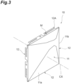
- the panel material 10 includes the body 11 and four legs 12.
- the body 11 is a plate-like portion having a square shape in a plan view.
- the body 11 has a surface 11a exposed to the outside.
- the surface 11a is a decorative surface.
- the surface 11a has an asymmetric decoration with respect to the central axis CX. In the example shown in FIG. 3 , the decoration of the surface 11a has a shape raised toward the outside.
- the body 11 has an outer edge portion 11b having a square shape in a plan view.
- the four legs 12 are plate-like portions for attaching the panel material 10 to the base materials 30.
- the four legs 12 are provided along four sides of the outer edge portion 11b of the body 11, and project from the outer edge portion 11b in a direction intersecting the body 11 (surface 11a).
- Each leg 12 extends along the outer edge portion 11b.
- the four legs 12 have the same shape as each other. Only one leg 12A of the four legs 12 is marked with a mark M. That is, the leg 12A is the same as any other leg 12 except for the mark M.
- through holes 12a and 12b, insertion holes 12c and 12d, a through hole 12e, and a depression 12f are provided in each leg 12.
- the through holes 12a and 12b are provided at both end portions of the leg 12 in the longer direction of the leg 12.
- the through hole 12a and the through hole 12b are line-symmetric with respect to the center line Lc of the leg 12 in the longer direction as a symmetry axis.
- the through holes 12a and 12b are used for fixing the panel materials 10 in the uppermost row to the uppermost base material 30 (base material 30A).
- Each of the through holes 12a and 12b has a shape into which a shaft portion of a fixing member 65 (see FIG. 20 ) such as a screw or the like can be inserted.
- the through holes 12a and 12b are round holes.
- the insertion hole 12c is provided at a position closer to the center line Lc than the through hole 12a in the longer direction of the leg 12.
- the insertion hole 12d is provided at a position closer to the center line Lc than the through hole 12b in the longer direction of the leg 12.
- the insertion hole 12c and the insertion hole 12d are line-symmetric with respect to the center line Lc as a symmetry axis.
- Each of the insertion holes 12c and 12d is a slotted hole extending in the longer direction of the leg 12, and has a shape into which a protrusion 34 (see FIG. 7 ) of the base material 30 can be inserted.
- the insertion holes 12c and 12d are slightly larger than the outer shape of the protrusion 34 in order to facilitate the insertion of the protrusion 34. Narrowed portions 12g and 12h are provided near the center of the insertion holes 12c and 12d in the longer direction in order to reduce the backlash of the protrusions 34, respectively. R angles are formed at both ends of the insertion holes 12c and 12d in the longer direction.
- the protrusions 34 of the base material 30 are inserted into the insertion holes 12c and 12d when the panel material 10 is attached to the base material 30 other than the uppermost row.
- the through hole 12e is provided at a position closer to the center line Lc than the insertion hole 12d in the longer direction of the leg 12.
- the through hole 12e has a shape into which a shaft portion of a fixing member 65 (see FIG. 19 ) can be inserted.
- the through hole 12e is an elongated hole extending in the longer direction of the leg 12.
- the through hole 12e is used for fixing the panel material 10 other than the uppermost row to the base material 30.
- the depression 12f is provided at a position closer to the center line Lc than the insertion hole 12c in the longer direction of the leg 12.
- the through hole 12e and the depression 12f are provided at positions that are line-symmetric with respect to the center line Lc as a symmetry axis.
- the depression 12f is used for avoiding interference between the head portion of the fixing member 65 for fixing the panel material 10 one row below the panel material 10 on which the depression 12f is provided to the base material 30 and the leg 12. In other words, the head portion of the fixing member 65 is inserted into the depression 12f.
- the mark M is further provided.
- the mark M is used to improve the discrimination of the orientation of the panel material 10.
- the support member 20 is an elongated member for supporting the base material 30.
- the material for forming the support member 20 is aluminum, for example.
- the support member 20 is produced, for example, by extrusion molding.
- the support member 20 defines a position at which the decorative structure 1 is attached.
- FIG. 5 is a perspective view showing the support member shown in FIG. 2 .
- FIG. 6(a) is a cross-sectional view taken along the line VIa-VIa of FIG. 5 .
- FIG. 6(b) is a cross-sectional view taken along the line VIb-VIb of FIG. 5 .
- the support member 20 includes an upper plate 21, side plates 22 and 23, a bottom plate 24, and a protruding piece 25.
- the upper plate 21 is a plate-like portion on which the base material 30 is mounted.
- the upper plate 21 is provided over the entire length of the support member 20 along the longer direction of the support member 20.
- the upper plate 21 has a mounting surface 21a on which the base material 30 is mounted.
- the side plates 22 and 23 are plate-like portions that support the upper plate 21.
- the side plates 22 and 23 are provided over the entire length of the support member 20 along the longer direction of the support member 20.
- the side plates 22 and 23 are provided so as to face each other across the upper plate 21, and extend in a direction intersecting the upper plate 21.
- One end of the side plate 22 is connected to one end of the upper plate 21 in the shorter direction of the upper plate 21.
- the upper plate 21, the side plate 22 and the side plate 23 constitute a mounting table on which the base material 30 is mounted.
- the mounting table has a U-shaped cross-sectional shape in a cross-section crossing the longer direction of the support member 20.
- the bottom plate 24 is a portion for fixing the support member 20 to the outer wall 2.
- the bottom plate 24 is provided over the entire length of the support member 20 along the longer direction of the support member 20.
- One end of the bottom plate 24 is connected to the other end of the side plate 22.
- the bottom plate 24 extends substantially in parallel with the upper plate 21 from the other end of the side plate 22 in a direction away from the upper plate 21.
- a groove 24a for positioning fixing members 61 and 62 such as a screw is provided in the bottom plate 24.
- the groove 24a extends along the longer direction of the bottom plate 24 and is provided over the entire length of the bottom plate 24.
- the distal ends of the fixing members 61 and 62 are positioned in the groove 24a of the bottom plate 24, and the fixing members 61 and 62 are driven into the groove 24a, whereby the support member 20 is fixed to the outer wall 2.
- the protruding piece 25 is connected to one end of the side plate 23 and protrudes from the mounting surface 21a of the upper plate 21.
- the protruding piece 25 is provided over the entire length of the support member 20 along the longer direction of the support member 20, and is partially missing in the longer direction of the support member 20.
- several missing portions 25a are provided in the protruding piece 25.
- the missing portion 25a has a shape into which the base material 30 can be fitted.
- the length of the missing portion 25a in the longer direction is substantially the same as that of a base 31 (see FIG. 7 ) described later in the shorter direction of the base 31.
- the upper support member 20, the lower support member 20, the left support member 20, the right support member 20, and the middle support member 20 are referred to as a support member 20A (second support member), a support member 20B (first support member), a support member 20C (third support member), a support member 20D (third support member), and a support member 20E (third support member), respectively (see FIG. 12 and the like).
- the support members 20A to 20D are arranged in a rectangular shape along the outer periphery of the decorative structure 1.
- the support members 20A and 20B extend in the lateral direction D1 and are arranged in parallel with each other.
- the support members 20C and 20D extend in the longitudinal direction D2 and are arranged in parallel with each other.
- Each of the support members 20A to 20D is disposed such that the mounting surface 21a faces away from the outer wall 2 and the bottom plate 24 is positioned inside.
- the support member 20E is disposed between the support members 20C and 20D and extends along the furring strip 4. That is, the support members 20C to 20E extend in the longitudinal direction D2 and are provided in parallel with each other in the lateral direction D1.
- the base material 30 is a member for attaching the panel material 10.
- the base material 30 is an elongated member.
- the material for forming the base material 30 is aluminum, for example.
- the base material 30 is produced, for example, by extrusion molding.
- FIG. 7 is a perspective view showing the base material shown in FIG. 2 .
- FIG 8 is a cross-sectional view taken along the line VIII-VIII of FIG 7 .
- the base material 30 includes the base 31, a mounting plate 32, a joint 33, the protrusion 34, a projection 35, and a bulge 36.
- the base 31 is a plate-like portion mounted on the upper plate 21 of the support member 20 and fixed to the support member 20.
- the base 31 is provided over the entire length of the base material 30 along the longer direction of the base material 30.
- the base 31 has a surface 31a and a surface 31b opposite to the surface 31a.
- the surface 31b is in contact with the mounting surface 21a of the support member 20.
- Two grooves 31c for positioning fixing members 63 such as a screw are provided on the surface 31a of the base 31.
- the groove 31c extends along the longer direction of the base 31 and is provided over the entire length of the base 31.
- a groove 31d extending from the surface 31a to the surface 31b on an end surface opposite to the mounting plate 32 is provided on the base 31.
- the distance between one end of the base 31 in the longer direction of the base 31 and the groove 31d nearest to the one end is substantially equal to the length (width) of the upper plate 21 in the shorter direction of the upper plate 21.
- the mounting plate 32 is a plate-shaped portion for attaching the panel material 10 to the base material 30.
- the mounting plate 32 is provided over the entire length of the base material 30 along the longer direction of the base material 30.
- the mounting plate 32 is provided at a right angle to the base 31.
- the mounting plate 32 has a surface 32a and a surface 32b opposite to the surface 32a. The surface 32a faces toward the base 31.
- a plurality of protrusions 34 are provided on the surface 32a. Each protrusion 34 protrudes in the direction normal to the surface 32a and extends in the longer direction of the base material 30.
- the protrusion 34 has a tapered shape that becomes thinner toward the distal end in order to facilitate insertion into the insertion holes 12c and 12d. That is, in the cross section intersecting with the longer direction of the base material 30, the protrusion 34 has a pentagonal cross section.
- the plurality of protrusions 34 are provided at regular intervals in the longer direction of the base material 30. The interval between the two adjacent protrusions 34 is substantially the same as the interval between the insertion hole 12c and the insertion hole 12d of the leg 12.
- a constriction 34a is provided at the root portion of the protrusion 34. The length of the constriction 34a in the direction in which the protrusion 34 protrudes is about the same as the thickness of one leg 12.
- Through holes 32c, 32d and 32e are provided in the mounting plate 32 to penetrate through the mounting plate 32.
- the through holes 32c, 32d and 32e penetrate through the mounting plate 32 from the surface 32a toward the surface 32b.
- the through holes 32c and 32d are used for fixing the panel material 10 in the uppermost row to the uppermost base material 30 (base material 30A).
- the through holes 32c and 32d have a shape into which the shaft portion of the fixing member 65 (see FIG. 20 ) can be inserted.
- the through holes 32c and 32d are elongated holes extending in the longer direction of the base material 30.
- the through holes 32c and 32d are provided so as to sandwich the protrusion 34 in the longer direction of the base material 30.
- the through hole 32e is used for fixing the panel material 10 other than the uppermost row to the base material 30.
- the through hole 32e has a shape into which the shaft portion of the fixing member 65 (see FIG. 19 ) can be inserted.
- the through hole 32e is a round hole.
- the through hole 32e is provided so as to be adjacent to the through hole 32d in the longer direction of the base material 30. In the longer direction of the base material 30, the through hole 32c, the protrusion 34, the through hole 32d, and the through hole 32e are arranged in this order.
- combinations of a through hole 32c, a protrusion 34, a through hole 32d, and a through hole 32e are provided at regular intervals.
- the joint 33 connects the base 31 and the mounting plate 32.
- the joint 33 is provided along the longer direction of the base material 30 over the entire length of the base material 30.
- the joint 33 connects the base 31 and the mounting plate 32 such that the base 31 and the mounting plate 32 are perpendicular to each other.
- One end of the joint 33 is connected to the surface 31a of the base 31, and the other end of the joint 33 is connected to the surface 32a of the mounting plate 32.
- a step portion is formed between the surface 31b and the joint 33.
- the projection 35 and the bulge 36 are portions for locking the base material 30 to the support member 20.
- the projection 35 is provided on a surface forming a step portion of the joint 33 and extends over the entire length of the base material 30 in the longer direction of the base material 30.
- the projection 35 projects to the same plane as the surface 31b of the base 31.
- a groove 37 is defined by the projection 35, the base 31 and the joint 33.
- the bulge 36 is provided on the surface 32b and extends over the entire length of the base material 30 in the longer direction of the base material 30.
- the bulge 36 and the projection 35 are perpendicular to each other, and a recess 38 is defined by the bulge 36 and the projection 35.
- the four base materials 30 extend in the lateral direction D1 and are arranged in parallel with each other at a predetermined interval in the longitudinal direction D2.
- the base material 30 positioned at one end (upper end) in the longitudinal direction D2 is referred to as a base material 30A (second base material)
- the base material 30 positioned at the other end (lower end) in the longitudinal direction D2 is referred to as a base material 30B (first base material)
- the base materials 30 positioned between the base material 30A and the base material 30B are referred to as a base material 30C (third base material) and a base material 30D (third base material) in order from the top (see FIG. 14 , etc.).
- the base material 30A is arranged such that the surface 31b faces the mounting surface 21a and the protrusion 34 protrudes downward, and the other base materials 30B, 30C and 30D are arranged such that the surface 31b faces the mounting surface 21a and the protrusion 34 protrudes upward.
- the base material 30A overlaps with the support member 20A when viewed from the direction D3.
- the base material 30B overlaps with the support member 20B when viewed from the direction D3.
- the base materials 30C and 30D are provided so as to intersect the support members 20C, 20E and 20D.
- the crown molding 40 is a member for hiding a bonder.
- the material for forming the crown molding 40 is, for example, a metal such as aluminum and titanium.
- the crown molding 40 is formed, for example, by extrusion molding.
- the leg 12 of the panel material 10, the support member 20 and the base material 30 are covered by the crown molding 40.
- FIG. 9 is a perspective view showing the crown molding shown in FIG. 1 .
- the crown molding 40 includes an upper plate 41, side plates 42 and 43, a bottom plate 44, and a locking piece 45.
- the upper plate 41 is a plate-like portion for covering a bonder.
- the upper plate 41 is provided along the longer direction of the crown molding 40 over the entire length of the crown molding 40.
- the side plates 42 and 43 are plate-like portions that support the upper plate 41.
- Each of the side plates 42 and 43 is provided along the longer direction of the crown molding 40 over the entire length of the crown molding 40.
- the side plates 42 and 43 are provided so as to face each other across the upper plate 41, and extend in a direction intersecting the upper plate 41.
- One end of the side plate 42 is connected to one end of the upper plate 41 in the shorter direction of the upper plate 41.
- One end of the side plate 43 is connected to the other end of the upper plate 41 in the shorter direction of the upper plate 41.
- the bottom plate 44 is a portion for fixing the crown molding 40 to the support member 20.
- the bottom plate 44 is provided over the entire length of the crown molding 40 along the longer direction of the crown molding 40.
- One end of the bottom plate 44 is connected to the other end of the side plate 42, and the bottom plate 44 extends substantially in parallel with the upper plate 41 from the other end of the side plate 42 in a direction away from the upper plate 41.
- the crown molding 40 is fixed to the side plate 23 of the support member 20 by driving fixing members 64 (see FIGS. 18 and 21 ) such as a screw into the bottom plate 44.
- the locking piece 45 is connected to the other end of the side plate 23 and protrudes inward from the other end of the side plate 23.
- the locking piece 45 is provided along the longer direction of the crown molding 40 over the entire length of the crown molding 40.
- the locking piece 45 is in contact with the leg 12 of the panel material 10.
- the four crown moldings 40 are located at the upper end, the lower end, and the left and right ends of the decorative structure 1, respectively, and form a frame of the decorative structure 1.
- the upper crown molding 40, the lower crown molding 40, the left crown molding 40, and the right crown molding 40 are referred to as a crown molding 40A, a crown molding 40B, a crown molding 40C, and a crown molding 40D, respectively (see FIGS. 18 and 21 , etc.).
- the crown moldings 40A to 40D are disposed such that the bottom plates 44 are placed on the side plates 23 of the support members 20A to 20D, and the locking pieces 45 are in contact with the legs 12, respectively.
- the fixing members 61 to 65 are made of stainless steel, for example.
- the fixing members 61 to 65 may be subjected to a high corrosion-resistant surface treatment.
- a fixing member with a packing may be used as the fixing members 61 to 65.
- the packing is made of, for example, ethylene propylene diene rubber (EPDM).
- FIG. 10 is a flowchart showing a method for constructing the decorative structure shown in FIG. 1 .
- FIG. 11 is a view for explaining a step of marking shown in FIG. 10 .
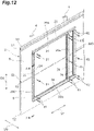
- FIG. 12 is a view for explaining a step of attaching the support member shown in FIG. 10 .
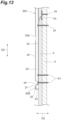
- FIG. 13 is a cross-sectional view taken along line XIII-XIII of FIG. 12 .
- FIG. 14 is a view for explaining a step of attaching the base material shown in FIG. 10 .
- FIG. 15 is a cross-sectional view taken along the line XV-XV of FIG. 14 .
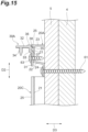
- FIG. 16 is a cross-sectional view taken along the line XVI-XVI of FIG. 14 .
- FIG. 17 is an enlarged view of a part of FIG. 14 .
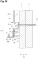
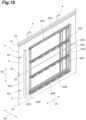
- FIG. 18 is a view for explaining a step of attaching the crown molding shown in FIG. 10 .
- FIG. 19 is a view for explaining a step of attaching the panel material shown in FIG. 10 .
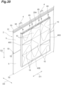
- FIG. 20 is a view for explaining a step of attaching the panel material shown in FIG. 10 .
- FIG. 21 is a view for explaining a step of attaching the upper crown molding shown in FIG. 10 .
- a step S1 of marking is performed first.
- a dashed line L1 is drawn on the outer wall 2 at a position where the decorative structure 1 is attached.
- the position where the decorative structure 1 is attached is, for example, the outer periphery of the decorative structure 1.
- the outer periphery of the decorative structure 1 is determined in accordance with the number of panel materials 10 to be installed in the lateral direction D1 and the longitudinal direction D2.
- a dashed line L2 indicating the position of the furring strip 4 is further drawn on the outer wall 2.
- a step S2 of attaching the support member 20 is performed.
- the support members 20A to 20D are arranged on the outer wall 2 along the dashed line L1.
- the support members 20A to 20D are disposed such that the bottom plate 24 faces the center of the frame surrounded by the dashed line L1, the protruding piece 25 protrudes outward (away from the outer wall 2), and the other end of the side plate 23 extends along the dashed line L1.
- the support member 20E is disposed on the outer wall 2 along the dashed line L2.
- the support member 20E is disposed such that the protruding piece 25 protrudes outward (away from the outer wall 2) and the distal end of the bottom plate 24 extends along the dashed line L2.
- Each support member 20 is fixed to the outer wall 2 by a fixing member 61 and a fixing member 62.
- Each support member 20 is fixed by a fixing member 61 or a fixing member 62 at three positions along the longer direction, for example.
- a fixing member 61 is used for the bottom plate 24 located on the furring strip 4, and a fixing member 62 shorter than the fixing member 61 is used for the bottom plate 24 not located on the furring strip 4.
- the fixing members 61 and 62 are driven in a state in which the distal ends of the fixing members 61 and 62 are positioned in the groove 24a. As a result, the fixing member 61 penetrates through the bottom plate 24, the siding panel 5, and the furring strip 4, and the fixing member 62 penetrates through the bottom plate 24 and sticks in the siding panel 5.
- the support members 20A and 20B are disposed across two furring strips 4 adjacent to each other in the lateral direction D1.
- Each of the support members 20A and 20B is fixed by the fixing members 61 on the two furring strips 4, and fixed by the fixing member 62 at the right end.
- the support members 20C to 20E are disposed across two siding panels 5 adjacent to each other in the longitudinal direction D2.
- Each of the support members 20C and 20E is fixed by the fixing members 61 at both ends and near the center in the longitudinal direction D2.
- the support member 20D is fixed by the fixing members 62 at both ends and near the center in the longitudinal direction D2. At this time, the fixing members 61 and 62 are driven into the vicinity of the male end portion 51 of the siding panel 5 so as not to hinder the follow-up property of the outer wall 2 at the centers of the support members 20C to 20E.
- a step S3 of attaching the base material 30 is performed.
- a plurality of base materials 30 are attached so as to extend in the lateral direction D1 and to be arranged in parallel with each other at predetermined intervals in the longitudinal direction D2.
- the base material 30A is attached to the support member 20A. More specifically, as shown in FIG. 15 , the base 31 of the base material 30A is superposed on and placed on the upper plate 21 of the support member 20A such that the protrusion 34 protrudes downward.
- the projection 35 of the base material 30A is pressed against the protruding piece 25 of the support member 20A from below, and the protruding piece 25 of the support member 20A is fitted into the recess 38 of the base material 30A. Then, the base material 30A is fixed to the upper plate 21 of the support member 20A by the fixing members 63 at three positions along the longer direction, for example.
- the base material 30B is attached to the support member 20B. More specifically, as shown in FIG. 16 , the base 31 of the base material 30B is placed on the upper plate 21 of the support member 20B such that the protrusion 34 protrudes upward. At this time, while the protruding piece 25 of the support member 20B is inserted into the groove 37 of the base material 30B, the base 31 of the base material 30B is superposed on the upper plate 21 of the support member 20B and placed thereon. Then, the base material 30B is fixed to the upper plate 21 of the support member 20B by the fixing members 63 at three positions along the longer direction, for example.
- Each of the base materials 30C and 30D is attached across the support members 20C to 20E. More specifically, as shown in FIG. 17 , the base 31 of each of the base materials 30C and 30D is placed across the upper plates 21 of the support members 20C to 20E such that the protrusion 34 protrudes upward. At this time, the base 31 and the projection 35 of each of the base materials 30C and 30D are fitted into the missing portions 25a of the support members 20C to 20E, and the positions of the base materials 30C and 30D in the lateral direction D1 are adjusted so that the grooves 31d of the base materials 30C and 30D overlap the corner formed by the upper plate 21 and the side plate 22 of the support member 20C. The base materials 30C and 30D are fixed to the upper plate 21 of each support member 20 by the fixing member 63, on the upper plates 21 of the support members 20C to 20E.
- the fixing member 63 is driven in a state where the distal end of the fixing member 63 is positioned in the groove 31c. As a result, the fixing member 63 penetrates through the base 31 and the upper plate 21.
- a step S4 of attaching the crown molding 40 (crown moldings 40B to 40D) is performed.
- the crown moldings 40B to 40D are attached.
- the crown moldings 40B to 40D are disposed so that the bottom plates 44 are superposed on the side plates 23 of the support members 20B, 20C and 20D, respectively, and that the locking pieces 45 of the crown moldings 40B to 40D form a U-shape.
- the crown moldings 40B to 40D are fixed to the side plates 23 of the support members 20B, 20C and 20D by the fixing members 64 in the vicinity of both ends in the longer direction of the crown molding 40, respectively.
- the fixing member 64 penetrates through the bottom plate 44 and the side plate 23.
- a step S5 of attaching the panel material 10 is performed.
- each panel material 10 is attached to two base materials 30 adjacent to each other in the longitudinal direction D2 among the base materials 30.
- Each panel material 10 is attached to the base material 30 by inserting the protrusions 34 of the base material 30 into the insertion holes 12c and 12d provided in at least one of the four legs 12.
- the direction of the panel material 10 is indicated by the direction (top, bottom, left and right) of the mark M.
- the mark M indicates the bottom, a worker orients the direction of the panel material 10 so that the leg 12A is located below.
- the lower left panel material 10 is attached to the base material 30D and the base material 30B.
- the first and second protrusions 34 from the left end of the base material 30B are inserted through the insertion holes 12c and 12d of the lower leg 12 among the four legs 12, respectively, and the first and second protrusions 34 from the left end of the base material 30D are inserted through the insertion holes 12c and 12d of the upper leg 12 among the four legs 12, respectively.
- the fixing member 65 is inserted through the through hole 12e and screwed into the through hole 32e.
- the distance in the longitudinal direction D2 between the surface 32a of the mounting plate 32 of the base material 30B and the surface 32a of the mounting plate 32 of the base material 30D is larger than the distance between the legs 12 of the panel material 10 facing each other by about the thickness of one leg 12.
- the upper leg 12 is fitted into the constriction 34a of the protrusion 34 of the base material 30D.
- a slight space is formed between the protrusion 34 and the peripheral edges of the insertion holes 12c and 12d in the constriction 34a, the leg 12 is fixed by the fixing member 65.
- the lower leg 12 is not fitted into the constriction 34a of the protrusion 34 of the base material 30B, but is positioned above the constriction 34a.
- the lengths of the insertion holes 12c and 12d in the lateral direction D1 are larger than the length of the protrusion 34 in the lateral direction D1, and the through hole 12e is an elongated hole extending in the lateral direction D1. Therefore, the position of the panel material 10 in the lateral direction D1 can be finely adjusted before the upper leg 12 is fixed to the base material 30B.
- the left end of the panel material 10 is brought into contact with (the locking piece 45 of) the crown molding 40C to position the panel material 10.
- another panel material 10 is sequentially attached to the right side of the attached panel material 10 by the same procedure.
- panel materials 10 are attached to the base material 30C and the base material 30D.
- the panel materials 10 are attached to the base material 30C and the base material 30D in order from the left end.
- the first and second protrusions 34 from the left end of the base material 30D are inserted through the insertion holes 12c and 12d of the lower leg 12 among the four legs 12, respectively, and the first and second protrusions 34 from the left end of the base material 30C are inserted through the insertion holes 12c and 12d of the upper leg 12 among the four legs 12, respectively.
- the head portion of the fixing member 65 used for fixing the lower panel material 10 is inserted into the depression 12f of the lower leg 12.
- the fixing member 65 is inserted through the through hole 12e and screwed into the through hole 32e.
- the distance in the longitudinal direction D2 between the surface 32a of the mounting plate 32 of the base material 30C and the surface 32a of the mounting plate 32 of the base material 30D is larger than the distance between the legs 12 of the panel material 10 facing each other by about the thickness of one leg 12.
- the upper leg 12 is fitted into the constriction 34a of the protrusion 34 of the base material 30C.
- the leg 12 of the lower panel material 10 is already fitted into the constriction 34a of the protrusion 34 of the base material 30D, the lower leg 12 is not fitted into the constriction 34a of the protrusion 34 of the base material 30D but is located above the constriction 34a.
- the left end of the panel material 10 is brought into contact with (the locking piece 45 of) the crown molding 40C to position the panel material 10. Then, another panel material 10 is sequentially attached to the right side of the attached panel material 10 by the same procedure.
- panel materials 10 are attached to the base material 30A and the base material 30C.
- the panel materials 10 are also attached to the base material 30A and the base material 30C in order from the left end.
- the first and second protrusions 34 from the left end of the base material 30C are inserted through the insertion holes 12c and 12d of the lower leg 12 among the four legs 12, respectively, and the upper leg 12 among the four legs 12 are placed on the surface 32b of the mounting plate 32 of the base material 30A.
- the head portion of the fixing member 65 used for fixing the lower panel material 10 is inserted into the depression 12f of the lower leg 12.
- the through hole 12a of the upper leg 12 overlaps with the first through hole 32d from the left end of the base material 30A in the longitudinal direction D2, and the through hole 12b of the upper leg 12 overlaps with the second through hole 32c from the left end of the base material 30A in the longitudinal direction D2. Therefore, the fixing members 65 are inserted through the through holes 12a and 12b and screwed into the through holes 32d and 32c, respectively.
- the distance in the longitudinal direction D2 between the surface 32b of the mounting plate 32 of the base material 30A and the surface 32a of the mounting plate 32 of the base material 30C is larger than the distance between the legs 12 of the panel material 10 facing each other by about the thickness of one leg 12. Since the leg 12 of the lower panel material 10 is already fitted into the constriction 34a of the protrusion 34 of the base material 30C, the lower leg 12 is not fitted into the constriction 34a of the protrusion 34 of the base material 30C but is located above the constriction 34a. At this position, there is almost no space between the protrusion 34 and the peripheral edges of the insertion holes 12c and 12d, and further movement of the leg 12 is suppressed by the narrowed portions 12g and 12h. Therefore, even if the lower leg 12 is not fixed to the base material 30C by the fixing member, the possibility of shifting its position is reduced.
- the through holes 32c and 32d are elongated holes extending in the lateral direction D1. Therefore, the position of the panel material 10 in the lateral direction D1 can be finely adjusted before the upper leg 12 is fixed to the base material 30A. Here, the left end of the panel material 10 is brought into contact with (the locking piece 45 of) the crown molding 40C to position the panel material 10. Then, another panel material 10 is sequentially attached to the right side of the attached panel material 10 by the same procedure.
- each panel material 10 in the lateral direction D1 is finely adjusted so as to align the positions in the lateral direction D1 of the adjacent panel materials 10 in the longitudinal direction D2.
- a step S6 of attaching the crown molding 40A is performed.
- the crown molding 40A is disposed such that the bottom plate 44 is superposed on the side plate 23 of the support member 20A and the locking piece 45 is in contact with the legs 12 of the panel materials 10 in the uppermost row.
- the crown molding 40A is fixed to the side plate 23 of the support member 20A by the fixing members 64 in the vicinity of both ends of the crown molding 40A in the longer direction of the crown molding 40A.
- the decorative structure 1 is constructed on the outer wall 2.
- the panel material 10 is attached by inserting the protrusions 34 of one of the two base materials 30 adjacent to each other in the longitudinal direction D2 into the insertion holes 12c and 12d provided in at least one leg 12 of the four legs 12 of the panel material 10.
- the four legs 12 are provided along four sides of the outer edge portion 11b having a square shape in a plan view, extend from the outer edge portion 11b in a direction intersecting (orthogonal to) the body 11, and have the same shape as each other. That is, except for the surface 11a, the panel material 10 is rotationally symmetric about the central axis CX of the body 11 at 90 °, 180 °, 270 °, and 360 °.
- the four legs 12 of the panel material 10 are rotationally symmetric about the central axis CX of the body 11 at 90 °, 180 °, 270 °, and 360 °. Therefore, the panel material 10 can be attached to the base material 30 even if the panel material 10 is rotated by any angle of 90 °, 180 °, 270 °, or 360 ° about the central axis CX of the body 11. As a result, it is possible to change the direction in which the panel material 10 is attached.
- the surface 11a of the panel material 10 has an asymmetrical decoration with respect to the central axis CX. Therefore, the decorative structure 1 can produce various appearances by arbitrarily attaching each panel material 10 at any one of the rotation angles of 90 °, 180 °, 270 ° and 360 ° for each panel material 10. Therefore, it is possible to improve the design of the decorative structure 1.
- Each of the plurality of support members 20 includes the protruding piece 25 which extends in a direction in which the support member 20 extends and protrudes in the direction D3. Since each base material 30 is positioned by the protruding piece 25 of the support member 20, the work of attaching the base material 30 can be simplified, and the construction accuracy of the base material 30 can be improved.
- the plurality of support members 20 include the support member 20A for supporting the base material 30A, the support member 20B for supporting the base material 30B, and the support members 20C to 20E for supporting the base materials 30C and 30D.
- the base material 30A is attached to the support member 20A in a state in which the projection 35 of the base material 30A is brought into contact with the protruding piece 25 of the support member 20A in the longitudinal direction D2. Since the position of the base material 30A in the longitudinal direction D2 is determined by this contact, the work for the worker to adjust the position of the base material 30A in the longitudinal direction D2 can be omitted. This makes it possible to simplify the work of attaching the base material 30A.
- the base material 30B is attached to the support member 20B in a state in which the protruding piece 25 of the support member 20B is fitted into the groove 37 provided in the base material 30B. Since the position of the base material 30B in the longitudinal direction D2 is determined by this fitting structure, the work for the worker to adjust the position of the base material 30B in the longitudinal direction D2 can be omitted. This makes it possible to simplify the work of attaching the base material 30B.
- the base materials 30C and 30D are attached to the support members 20C, 20D and 20E in a state in which the base materials 30C and 30D are fitted into the missing portions 25a provided in the protruding pieces 25 of the support members 20C, 20D and 20E. Since the positions of the base materials 30C and 30D in the longitudinal direction D2 are determined by these fitting structures, the work for the worker to adjust the position of the base materials 30C and 30D in the longitudinal direction D2 can be omitted. This makes it possible to simplify the work of attaching the base materials 30C and 30D.
- the base material 30 can be systematically attached to the support member 20.
- the leg 12A of the panel material 10 is marked with the mark M. This makes it possible to indicate the direction in which the panel material 10 is attached by the direction (top, bottom, left and right) of the mark M in the work instruction sheet. Therefore, the worker can easily judge the direction in which the panel material 10 is attached, so that the workability of the panel material 10 can be improved.
- the support members 20A to 20E are mounted on the outer wall 2, and the base materials 30A to 30D are mounted on the support members 20A to 20E. Further, the plurality of panel materials 10 are attached to the base materials 30A to 30D. Therefore, the panel material 10 can be attached without influence of the shape of the outer wall 2.
- the support members 20C to 20E are arranged in the longitudinal direction D2 orthogonal to a direction (lateral direction D1) in which the siding panel 5 extends, and are attached across two siding panels 5 adjacent to each other in the longitudinal direction D2.
- This configuration makes it difficult for the female end portion 52 of the upper siding panel 5 and the male end portion 51 of the lower siding panel 5 to disengaged from each other. As a result, the wind pressure resistance performance of the outer wall 2 can be improved.
- the panel material 10 at the left end is positioned by bringing the left end of the panel material 10 into contact with (the locking piece 45 of) the crown molding 40C.
- the panel material 10 other than the left end is positioned by bringing the left end of the panel material 10 into contact with the right end of the panel material 10 located on the left side of the panel material 10. This configuration makes it possible to reduce the gap (joint) between the two panel materials 10 adjacent to each other in the lateral direction D1.
- the protrusions 34 of the base materials 30C and 30D are inserted through the insertion holes 12c and 12d provided in the leg 12 of the lower panel material 10 and the insertion holes 12c and 12d provided in the leg 12 of the upper panel material 10, and the legs 12 of the two panel materials 10 adjacent to each other in the longitudinal direction D2 are attached to the base materials 30C and 30D.
- This configuration makes it possible to reduce the gap (joint) between the two panel materials 10 adjacent to each other in the longitudinal direction D2.
- the decorative structure, the panel material, and the method for constructing the decorative structure according to the present disclosure are not limited to the above-described embodiments.
- the outer wall 2 on which the decorative structure 1 is installed is configured by attaching a plurality of siding panels 5 so as to extend in the horizontal direction, but the outer wall 2 is not limited to this configuration.
- the outer wall 2 on which the decorative structure 1 is installed may be configured by attaching a plurality of siding panels 5 so as to extend in the vertical direction.
- the decorative structure 1 may be provided by being rotated 90 degrees clockwise.
- the decorative structure 1 may be installed on not only the outer wall but also the inner wall.
- the decorative shape of the surface 11a may be a shape inclined from one side to the other side among a pair of mutually facing sides of the outer edge portion 11b.
- the decorative structure 1 includes nine panel materials 10, but the number of panel materials 10 can be changed depending on the size of the desired decorative structure 1.
- the lengths of the support members 20A and 20B, the base materials 30A to 30D, and the crown moldings 40A and 40B are adjusted depending on the number of the panel materials 10 in the lateral direction D1.
- the lengths of the support members 20C to 20E and the crown moldings 40C and 40D, and the number of the base materials 30 are adjusted depending on the number of the panel materials 10 in the longitudinal direction D2.
- the support members 20A to 20E have the same shape but may have different shapes.
- the base materials 30A to 30D have the same shape but may have different shapes.
- the base material 30A may include at least the projection 35 which is contact with the protruding piece 25 of the support member 20A in the longitudinal direction D2, and the groove 37 may not be provided.
- At least the groove 37 which is fitted into the protruding piece 25 of the support member 20B may be provided in the base material 30B, and the base material 30B may not include the bulge 36.
- the base materials 30C and 30D may have a shape that fits into the missing portions 25a provided in the support members 20C to 20E, and the groove 37 may not be provided.
- the crown moldings 40A to 40D have the same shape, but may have different shapes.
Landscapes
- Engineering & Computer Science (AREA)
- Architecture (AREA)
- Civil Engineering (AREA)
- Structural Engineering (AREA)
- Finishing Walls (AREA)
Abstract
Description
- The present disclosure relates to a decorative structure, a panel material, and a method for constructing a decorative structure.
- Panel materials are sometimes placed on the outer walls of buildings. For example,
Patent Document 1 describes an exterior structure in which a panel material is attached to a base material attached to a wall surface. - Patent Document 1:
Japanese Unexamined Patent Application Publication No. 2003-253847 - In the exterior structure described in
Patent Document 1, panel locking bolts are provided at a predetermined pitch in the vertical direction on the base material, and the panel material is attached by hooking a hook-shaped notch provided on the side surface of the panel material on the panel locking bolts. Therefore, the direction in which the panel material is attached is fixed. In the present technical field, it is desired to freely change the direction in which the panel material is attached. - The present disclosure describes a decorative structure, a panel material, and a method for constructing a decorative structure capable of changing the direction in which a panel material is attached.
- A decorative structure according to one aspect of the present disclosure includes: a plurality of base materials extending in a first direction and provided in parallel with each other at predetermined intervals in a second direction intersecting the first direction; and a plurality of panel materials, each of the plurality of panel materials being attached to two base materials adjacent to each other in the second direction among the plurality of base materials. Each of the plurality of base materials includes a protrusion protruding in the second direction. Each of the plurality of panel materials includes a body including an outer edge portion having a square shape in a plan view, and four legs provided along four sides of the outer edge portion and extending from the outer edge portion in a direction intersecting the body. The four legs have the same shape as each other. An insertion hole into which the protrusion can be inserted is provided in each of the four legs. The panel material is attached by inserting the protrusion of one of the two base materials through the insertion hole provided in one of the four legs.
- In this decorative structure, the panel material is attached by inserting the protrusion of one of two base materials adjacent to each other in the second direction into the insertion hole provided in one of the four legs of the panel material. The four legs are provided along four sides of the outer edge portion having a square shape in a plan view, extend from the outer edge portion in a direction intersecting with the body, and have the same shape as each other. That is, the four legs of the panel material are rotationally symmetric about the center point of the body at 90 °, 180 °, 270 °, and 360 °. Therefore, the panel material can be attached to the base material even if the panel material is rotated by any angle of 90 °, 180 °, 270 °, or 360 ° about the central point of the body. As a result, it is possible to change the direction in which the panel material is attached.
- The decorative structure may further include a plurality of elongated support members that support the plurality of base materials. Each of the plurality of support members may include a protruding piece that extends in a direction in which the support member extends and protrudes in a third direction intersecting the first direction and the second direction. The plurality of base materials may be positioned by the protruding piece. In this case, the plurality of base materials are positioned by the protruding pieces of the support members. Therefore, when the decorative structure is constructed, the work of attaching the base material can be simplified.
- The plurality of base materials may include a first base material located at one end of the plurality of base materials in the second direction. The plurality of support members may include a first support member that supports the first base material. The first support member may extend in the first direction and may overlap the first base material when viewed from the third direction. A groove into which the protruding piece of the first support member fits may be provided in the first base material. In this case, the first base material can be positioned by fitting the protruding piece of the first support member in the groove of the first base material. Therefore, when the decorative structure is constructed, the work of attaching the first base material can be simplified.
- The plurality of base materials may further include a second base material located at the other end of the plurality of base materials in the second direction. The plurality of support members may further include a second support member that supports the second base material. The second support member may extend in the first direction and may overlap the second base material when viewed from the third direction. The second base material may further include a projection that is contact with the protrusion of the second support member in the second direction. In this case, the projection of the second base material is brought into contact with the protruding piece of the second support member in the second direction, whereby the second base material is positioned in the second direction. Therefore, when the decorative structure is constructed, the work of attaching the second base material can be simplified.
- The plurality of base materials may further include a third base material located between the first base material and the second base material in the second direction. The plurality of support members may further include a plurality of third support members that support the third base material. The plurality of third support members may extend in the second direction and may be provided in parallel with each other in the first direction. Missing portions into which the third base material fits may be provided in the protruding pieces of the plurality of third support members. In this case, the third base material can be positioned by fitting the third base material to the missing portions provided on the protruding pieces of the plurality of third support members. Therefore, when the decorative structure is constructed, the work of attaching the third base material can be simplified.
- A panel material according to another aspect of the present disclosure includes: a body including an outer edge portion having a square shape in a plan view; and four legs provided along four sides of the outer edge portion and extending from the outer edge portion in a direction intersecting the body. The four legs have the same shape as each other. An insertion hole into which a protrusion of a base material can be inserted is provided in each of the four legs.
- In this panel material, the four legs are provided along four sides of the outer edge portion having a square shape in a plan view, extend from the outer edge portion in a direction intersecting with the body, and have the same shape as each other. That is, the four legs of the panel material are rotationally symmetric about the center point of the body at 90 °, 180 °, 270 °, and 360 °. Therefore, the panel material can be attached to the base material even if the panel material is rotated by any angle of 90 °, 180 °, 270 °, or 360 ° about the central point of the body. As a result, it is possible to change the direction in which the panel material is attached.
- A method for constructing a decorative structure according to still another aspect of the present disclosure includes: a step of attaching a plurality of base materials so that each of the plurality of base materials extends in a first direction and the plurality of base materials are arranged in parallel with each other at predetermined intervals in a second direction intersecting the first direction; and a step of attaching a panel material to two base materials adjacent to each other in the second direction among the plurality of base materials. Each of the plurality of base materials includes a protrusion protruding in the second direction. The panel material includes a body including an outer edge portion having a square shape in a plan view, and four legs provided along four sides of the outer edge portion and extending from the outer edge portion in a direction intersecting the body. The four legs have the same shape as each other. An insertion hole into which the protrusion can be inserted is provided in each of the four legs. In the step of attaching the panel material, the panel material is attached by inserting the protrusion of one base material of the two base materials into the insertion hole provided in one of the four legs.
- In this method for constructing the decorative structure, the panel material is attached by inserting the protrusion of one of two base materials adjacent to each other in the second direction into the insertion hole provided in one of the four legs of the panel material. The four legs are provided along four sides of the outer edge portion having a square shape in a plan view, extend from the outer edge portion in a direction intersecting with the body, and have the same shape as each other. That is, the four legs of the panel material are rotationally symmetric about the center point of the body at 90 °, 180 °, 270 °, and 360 °. Therefore, the panel material can be attached to the base material even if the panel material is rotated by any angle of 90 °, 180 °, 270 °, or 360 ° about the central point of the body. As a result, it is possible to change the direction in which the panel material is attached.
- According to each aspect and each embodiment of the present disclosure, the direction in which the panel material is attached can be changed.
-
-
FIG. 1 is a perspective view showing a decorative structure according to an embodiment. -
FIG. 2 is a perspective view showing support members and base materials of the decorative structure shown inFIG. 1 . -
FIG. 3 is a perspective view showing the panel material shown inFIG. 1 . -
FIG. 4 is an enlarged view showing a leg of the panel material shown inFIG. 3 . -
FIG. 5 is a perspective view showing the support member shown inFIG. 2 . -
FIG. 6(a) is a cross-sectional view taken along the line VIa-VIa ofFIG. 5 .FIG. 6(b) is a cross-sectional view taken along the line VIb-VIb ofFIG. 5 . -
FIG. 7 is a perspective view showing the base material shown inFIG. 2 . -
FIG. 8 is a cross-sectional view taken along the line VIII-VIII ofFIG. 7 . -
FIG. 9 is a perspective view showing the crown molding shown inFIG. 1 . -
FIG. 10 is a flowchart showing a method for constructing the decorative structure shown inFIG. 1 . -
FIG 11 is a view for explaining a step of marking shown inFIG 10 . -
FIG. 12 is a view for explaining a step of attaching the support member shown inFIG. 10 . -
FIG. 13 is a cross-sectional view taken along line XIII-XIII ofFIG. 12 . -
FIG. 14 is a view for explaining a step of attaching the base material shown inFIG. 10 . -
FIG. 15 is a cross-sectional view taken along the line XV-XV ofFIG. 14 . -
FIG. 16 is a cross-sectional view taken along the line XVI-XVI ofFIG. 14 . -
FIG. 17 is an enlarged view of a part ofFIG. 14 . -
FIG. 18 is a view for explaining a step of attaching the crown molding shown inFIG. 10 . -
FIG. 19 is a view for explaining a step of attaching the panel material shown inFIG. 10 . -
FIG. 20 is a view for explaining a step of attaching the panel material shown inFIG. 10 . -
FIG. 21 is a view for explaining a step of attaching the upper crown molding shown inFIG. 10 . -
FIG. 22 is a view showing another example of an outer wall. -
FIG. 23 is a perspective view showing another example of a panel material. - Hereinafter, embodiments of the present disclosure will be described in detail with reference to the drawings. In the description of the drawings, the same components are designated with the same reference signs, and the redundant description is omitted. In each drawing, a lateral direction D1 (first direction), a longitudinal direction D2 (second direction), and a direction D3 (third direction) are shown. The longitudinal direction D2 is a direction (vertical direction) intersecting with (here, orthogonal to) the lateral direction D1 and the direction D3. The direction D3 is a direction intersecting with (here, orthogonal to) the lateral direction D1 and the longitudinal direction D2. The longitudinal direction D2 is a vertical direction, for example, and the lateral direction D1 and the direction D3 are horizontal directions, for example.
-
FIG. 1 is a perspective view showing a decorative structure according to an embodiment.FIG. 2 is a perspective view showing support members and base materials of the decorative structure shown inFIG. 1 . Adecorative structure 1 shown inFIG. 1 is used for decorating a building. In the present embodiment, thedecorative structure 1 is constructed on theouter wall 2. Examples of theouter wall 2 include an outer wall composed of metal siding panels, an outer wall made of reinforced concrete (RC), an outer wall made of a ceramic-based outer covering material, and an outer wall made of autoclaved lightweight concrete (ALC). - In the example shown in
FIGS. 1 and2 , theouter wall 2 is formed by a plurality ofsiding panels 5 attached so as to extend in the horizontal direction. Thesiding panel 5 is an elongated metal siding. Thesiding panel 5 includes amale end portion 51, afemale end portion 52, and a fixingportion 53. Themale end portion 51 is provided at one end of thesiding panel 5 in the shorter direction of thesiding panel 5 and extends along the longer direction of thesiding panel 5 over the entire length of thesiding panel 5. Thefemale end portion 52 is provided at the other end of thesiding panel 5 in the shorter direction of thesiding panel 5, and extends along the longer direction of thesiding panel 5 over the entire length of thesiding panel 5. Themale end portion 51 and thefemale end portion 52 are configured to be able to fit to each other. Specifically, themale end portion 51 has a protruding shape protruding in the shorter direction of thesiding panel 5. Thefemale end portion 52 has a recessed shape recessed in the shorter direction of thesiding panel 5. - The fixing
portion 53 is a portion for fixing thesiding panel 5 to thefurring strip 4. The fixingportion 53 is provided at a position closer to the back surface than themale end portion 51 at one end in the shorter direction of thesiding panel 5, and extends along the longer direction of thesiding panel 5 over the entire length of thesiding panel 5. Thesiding panel 5 is fixed to thefurring strip 4 by driving fixing members 54 (seeFIG. 13 ) such as a nail or the like into the fixingportion 53. Thesiding panel 5 is not fixed to thefurring strip 4 at thefemale end portion 52. Therefore, even if an external force is applied to theouter wall 2 due to an earthquake or the like, theouter wall 2 deforms in response to the external force. That is, it is possible to obtain the follow-up property to the external force caused by an earthquake or the like. - In the example shown in
FIGS. 1 and2 , eachsiding panel 5 is arranged to extend in the lateral direction D1. The plurality ofsiding panels 5 are arranged in the longitudinal direction D2. In other words, thesiding panel 5 is attached to thefurring strip 4 extending in the longitudinal direction D2 so as to extend in the horizontal direction. Specifically, eachsiding panel 5 is disposed such that themale end portion 51 and the fixingportion 53 are positioned above and thefemale end portion 52 is positioned below. Thefemale end portion 52 of theupper siding panel 5 and themale end portion 51 of thelower siding panel 5 are fitted to each other, so that the twosiding panels 5 adjacent to each other in the longitudinal direction D2 are connected. - As shown in
FIGS. 1 and2 , thedecorative structure 1 includes a plurality ofpanel materials 10, a plurality ofsupport members 20, a plurality ofbase materials 30, and a plurality ofcrown moldings 40. In the present embodiment, thedecorative structure 1 includes ninepanel materials 10, fivesupport members 20, fourbase materials 30, and fourcrown moldings 40. - The
panel material 10 is a decorative member. Eachpanel material 10 is attached to twobase materials 30 which are adjacent to each other in the longitudinal direction D2 among thebase materials 30. Thepanel material 10 can be installed in four directions. Specifically, thepanel material 10 is rotationally symmetric about the central axis CX of abody 11 at 90 °, 180 °, 270 °, and 360 °, except for thesurface 11a of thebody 11 described later. Therefore, thepanel material 10 is attached in a direction rotated by any one of 90 °, 180 °, 270 ° and 360 ° about the central axis CX of thebody 11. The material of thepanel material 10 is, for example, a metal such as aluminum or titanium, or a resin such as plastic or vinyl chloride. Thepanel material 10 is produced, for example, by punching a metal plate and then bending the plate. - The
panel material 10 will be described in detail with further reference toFIGS. 3 and4 .FIG. 3 is a perspective view showing the panel material shown inFIG. 1 .FIG. 4 is an enlarged view showing a leg of the panel material shown inFIG. 3 . As shown inFIG. 3 , thepanel material 10 includes thebody 11 and fourlegs 12. - The
body 11 is a plate-like portion having a square shape in a plan view. Thebody 11 has asurface 11a exposed to the outside. Thesurface 11a is a decorative surface. Thesurface 11a has an asymmetric decoration with respect to the central axis CX. In the example shown inFIG. 3 , the decoration of thesurface 11a has a shape raised toward the outside. Thebody 11 has anouter edge portion 11b having a square shape in a plan view. - The four
legs 12 are plate-like portions for attaching thepanel material 10 to thebase materials 30. The fourlegs 12 are provided along four sides of theouter edge portion 11b of thebody 11, and project from theouter edge portion 11b in a direction intersecting the body 11 (surface 11a). Eachleg 12 extends along theouter edge portion 11b. The fourlegs 12 have the same shape as each other. Only oneleg 12A of the fourlegs 12 is marked with a mark M. That is, theleg 12A is the same as anyother leg 12 except for the mark M. - As shown in
FIG. 4 , throughholes insertion holes hole 12e, and adepression 12f are provided in eachleg 12. - The through
holes leg 12 in the longer direction of theleg 12. The throughhole 12a and the throughhole 12b are line-symmetric with respect to the center line Lc of theleg 12 in the longer direction as a symmetry axis. The throughholes panel materials 10 in the uppermost row to the uppermost base material 30 (base material 30A). Each of the throughholes FIG. 20 ) such as a screw or the like can be inserted. In the present embodiment, the throughholes - The
insertion hole 12c is provided at a position closer to the center line Lc than the throughhole 12a in the longer direction of theleg 12. Theinsertion hole 12d is provided at a position closer to the center line Lc than the throughhole 12b in the longer direction of theleg 12. Theinsertion hole 12c and theinsertion hole 12d are line-symmetric with respect to the center line Lc as a symmetry axis. Each of the insertion holes 12c and 12d is a slotted hole extending in the longer direction of theleg 12, and has a shape into which a protrusion 34 (seeFIG. 7 ) of thebase material 30 can be inserted. The insertion holes 12c and 12d are slightly larger than the outer shape of theprotrusion 34 in order to facilitate the insertion of theprotrusion 34.Narrowed portions protrusions 34, respectively. R angles are formed at both ends of the insertion holes 12c and 12d in the longer direction. Theprotrusions 34 of thebase material 30 are inserted into the insertion holes 12c and 12d when thepanel material 10 is attached to thebase material 30 other than the uppermost row. - The through
hole 12e is provided at a position closer to the center line Lc than theinsertion hole 12d in the longer direction of theleg 12. The throughhole 12e has a shape into which a shaft portion of a fixing member 65 (seeFIG. 19 ) can be inserted. In the present embodiment, the throughhole 12e is an elongated hole extending in the longer direction of theleg 12. The throughhole 12e is used for fixing thepanel material 10 other than the uppermost row to thebase material 30. Thedepression 12f is provided at a position closer to the center line Lc than theinsertion hole 12c in the longer direction of theleg 12. The throughhole 12e and thedepression 12f are provided at positions that are line-symmetric with respect to the center line Lc as a symmetry axis. Thedepression 12f is used for avoiding interference between the head portion of the fixingmember 65 for fixing thepanel material 10 one row below thepanel material 10 on which thedepression 12f is provided to thebase material 30 and theleg 12. In other words, the head portion of the fixingmember 65 is inserted into thedepression 12f. - Since the
leg 12A is shown inFIG. 4 , the mark M is further provided. The mark M is used to improve the discrimination of the orientation of thepanel material 10. - The
support member 20 is an elongated member for supporting thebase material 30. The material for forming thesupport member 20 is aluminum, for example. Thesupport member 20 is produced, for example, by extrusion molding. Thesupport member 20 defines a position at which thedecorative structure 1 is attached. - The
support member 20 will be described in detail with further reference toFIGS. 5 ,6(a) and6(b) .FIG. 5 is a perspective view showing the support member shown inFIG. 2 .FIG. 6(a) is a cross-sectional view taken along the line VIa-VIa ofFIG. 5 .FIG. 6(b) is a cross-sectional view taken along the line VIb-VIb ofFIG. 5 . As shown inFIGS. 5 ,6(a) and 6(b) , thesupport member 20 includes anupper plate 21,side plates bottom plate 24, and a protrudingpiece 25. - The
upper plate 21 is a plate-like portion on which thebase material 30 is mounted. Theupper plate 21 is provided over the entire length of thesupport member 20 along the longer direction of thesupport member 20. Theupper plate 21 has a mountingsurface 21a on which thebase material 30 is mounted. Theside plates upper plate 21. Theside plates support member 20 along the longer direction of thesupport member 20. Theside plates upper plate 21, and extend in a direction intersecting theupper plate 21. One end of theside plate 22 is connected to one end of theupper plate 21 in the shorter direction of theupper plate 21. One end of theside plate 23 is connected to the other end of theupper plate 21 in the shorter direction of theupper plate 21. Theupper plate 21, theside plate 22 and theside plate 23 constitute a mounting table on which thebase material 30 is mounted. The mounting table has a U-shaped cross-sectional shape in a cross-section crossing the longer direction of thesupport member 20. - The
bottom plate 24 is a portion for fixing thesupport member 20 to theouter wall 2. Thebottom plate 24 is provided over the entire length of thesupport member 20 along the longer direction of thesupport member 20. One end of thebottom plate 24 is connected to the other end of theside plate 22. Thebottom plate 24 extends substantially in parallel with theupper plate 21 from the other end of theside plate 22 in a direction away from theupper plate 21. Agroove 24a for positioning fixingmembers 61 and 62 (seeFIG. 12 ) such as a screw is provided in thebottom plate 24. Thegroove 24a extends along the longer direction of thebottom plate 24 and is provided over the entire length of thebottom plate 24. The distal ends of the fixingmembers groove 24a of thebottom plate 24, and the fixingmembers groove 24a, whereby thesupport member 20 is fixed to theouter wall 2. - The protruding
piece 25 is connected to one end of theside plate 23 and protrudes from the mountingsurface 21a of theupper plate 21. The protrudingpiece 25 is provided over the entire length of thesupport member 20 along the longer direction of thesupport member 20, and is partially missing in the longer direction of thesupport member 20. In other words, several missingportions 25a are provided in the protrudingpiece 25. The missingportion 25a has a shape into which thebase material 30 can be fitted. The length of the missingportion 25a in the longer direction is substantially the same as that of a base 31 (seeFIG. 7 ) described later in the shorter direction of thebase 31. - In the example shown in
FIG. 2 , fivesupport members 20 are arranged. In order to distinguish them, theupper support member 20, thelower support member 20, theleft support member 20, theright support member 20, and themiddle support member 20 are referred to as asupport member 20A (second support member), asupport member 20B (first support member), asupport member 20C (third support member), asupport member 20D (third support member), and asupport member 20E (third support member), respectively (seeFIG. 12 and the like). - The
support members 20A to 20D are arranged in a rectangular shape along the outer periphery of thedecorative structure 1. Thesupport members support members support members 20A to 20D is disposed such that the mountingsurface 21a faces away from theouter wall 2 and thebottom plate 24 is positioned inside. Thesupport member 20E is disposed between thesupport members furring strip 4. That is, thesupport members 20C to 20E extend in the longitudinal direction D2 and are provided in parallel with each other in the lateral direction D1. - The
base material 30 is a member for attaching thepanel material 10. Thebase material 30 is an elongated member. The material for forming thebase material 30 is aluminum, for example. Thebase material 30 is produced, for example, by extrusion molding. - The
base material 30 will be described in detail with further reference toFIGS. 7 and8 .FIG. 7 is a perspective view showing the base material shown inFIG. 2 .FIG 8 is a cross-sectional view taken along the line VIII-VIII ofFIG 7 . As shown inFIGS. 7 and8 , thebase material 30 includes thebase 31, a mountingplate 32, a joint 33, theprotrusion 34, aprojection 35, and abulge 36. - The
base 31 is a plate-like portion mounted on theupper plate 21 of thesupport member 20 and fixed to thesupport member 20. Thebase 31 is provided over the entire length of thebase material 30 along the longer direction of thebase material 30. Thebase 31 has asurface 31a and asurface 31b opposite to thesurface 31a. Thesurface 31b is in contact with the mountingsurface 21a of thesupport member 20. Twogrooves 31c for positioning fixing members 63 (seeFIG. 14 ) such as a screw are provided on thesurface 31a of thebase 31. Thegroove 31c extends along the longer direction of thebase 31 and is provided over the entire length of thebase 31. Agroove 31d extending from thesurface 31a to thesurface 31b on an end surface opposite to the mountingplate 32 is provided on thebase 31. The distance between one end of the base 31 in the longer direction of thebase 31 and thegroove 31d nearest to the one end is substantially equal to the length (width) of theupper plate 21 in the shorter direction of theupper plate 21. - The mounting
plate 32 is a plate-shaped portion for attaching thepanel material 10 to thebase material 30. The mountingplate 32 is provided over the entire length of thebase material 30 along the longer direction of thebase material 30. The mountingplate 32 is provided at a right angle to thebase 31. The mountingplate 32 has asurface 32a and asurface 32b opposite to thesurface 32a. Thesurface 32a faces toward thebase 31. - A plurality of
protrusions 34 are provided on thesurface 32a. Eachprotrusion 34 protrudes in the direction normal to thesurface 32a and extends in the longer direction of thebase material 30. Theprotrusion 34 has a tapered shape that becomes thinner toward the distal end in order to facilitate insertion into the insertion holes 12c and 12d. That is, in the cross section intersecting with the longer direction of thebase material 30, theprotrusion 34 has a pentagonal cross section. The plurality ofprotrusions 34 are provided at regular intervals in the longer direction of thebase material 30. The interval between the twoadjacent protrusions 34 is substantially the same as the interval between theinsertion hole 12c and theinsertion hole 12d of theleg 12. Aconstriction 34a is provided at the root portion of theprotrusion 34. The length of theconstriction 34a in the direction in which theprotrusion 34 protrudes is about the same as the thickness of oneleg 12. - Through
holes plate 32 to penetrate through the mountingplate 32. The throughholes plate 32 from thesurface 32a toward thesurface 32b. The throughholes panel material 10 in the uppermost row to the uppermost base material 30 (base material 30A). The throughholes FIG. 20 ) can be inserted. The throughholes base material 30. The throughholes protrusion 34 in the longer direction of thebase material 30. - The through
hole 32e is used for fixing thepanel material 10 other than the uppermost row to thebase material 30. The throughhole 32e has a shape into which the shaft portion of the fixing member 65 (seeFIG. 19 ) can be inserted. The throughhole 32e is a round hole. The throughhole 32e is provided so as to be adjacent to the throughhole 32d in the longer direction of thebase material 30. In the longer direction of thebase material 30, the throughhole 32c, theprotrusion 34, the throughhole 32d, and the throughhole 32e are arranged in this order. In the mountingplate 32, combinations of a throughhole 32c, aprotrusion 34, a throughhole 32d, and a throughhole 32e are provided at regular intervals. - The joint 33 connects the
base 31 and the mountingplate 32. The joint 33 is provided along the longer direction of thebase material 30 over the entire length of thebase material 30. The joint 33 connects thebase 31 and the mountingplate 32 such that thebase 31 and the mountingplate 32 are perpendicular to each other. One end of the joint 33 is connected to thesurface 31a of thebase 31, and the other end of the joint 33 is connected to thesurface 32a of the mountingplate 32. A step portion is formed between thesurface 31b and the joint 33. - The
projection 35 and thebulge 36 are portions for locking thebase material 30 to thesupport member 20. Theprojection 35 is provided on a surface forming a step portion of the joint 33 and extends over the entire length of thebase material 30 in the longer direction of thebase material 30. Theprojection 35 projects to the same plane as thesurface 31b of thebase 31. Agroove 37 is defined by theprojection 35, thebase 31 and the joint 33. Thebulge 36 is provided on thesurface 32b and extends over the entire length of thebase material 30 in the longer direction of thebase material 30. Thebulge 36 and theprojection 35 are perpendicular to each other, and arecess 38 is defined by thebulge 36 and theprojection 35. - In the example shown in
FIG. 2 , the fourbase materials 30 extend in the lateral direction D1 and are arranged in parallel with each other at a predetermined interval in the longitudinal direction D2. In order to distinguish them, thebase material 30 positioned at one end (upper end) in the longitudinal direction D2 is referred to as abase material 30A (second base material), thebase material 30 positioned at the other end (lower end) in the longitudinal direction D2 is referred to as abase material 30B (first base material), and thebase materials 30 positioned between thebase material 30A and thebase material 30B are referred to as abase material 30C (third base material) and abase material 30D (third base material) in order from the top (seeFIG. 14 , etc.). - The
base material 30A is arranged such that thesurface 31b faces the mountingsurface 21a and theprotrusion 34 protrudes downward, and theother base materials surface 31b faces the mountingsurface 21a and theprotrusion 34 protrudes upward. Thebase material 30A overlaps with thesupport member 20A when viewed from the direction D3. Thebase material 30B overlaps with thesupport member 20B when viewed from the direction D3. Thebase materials support members support member 20 and thebase material 30 will be described in detail in the description of a method for constructing thedecorative structure 1. - The
crown molding 40 is a member for hiding a bonder. The material for forming thecrown molding 40 is, for example, a metal such as aluminum and titanium. Thecrown molding 40 is formed, for example, by extrusion molding. Theleg 12 of thepanel material 10, thesupport member 20 and thebase material 30 are covered by thecrown molding 40. - The
crown molding 40 will be described in detail with further reference toFIG. 9. FIG. 9 is a perspective view showing the crown molding shown inFIG. 1 . As shown inFIG. 9 , thecrown molding 40 includes anupper plate 41,side plates bottom plate 44, and alocking piece 45. - The
upper plate 41 is a plate-like portion for covering a bonder. Theupper plate 41 is provided along the longer direction of thecrown molding 40 over the entire length of thecrown molding 40. Theside plates upper plate 41. Each of theside plates crown molding 40 over the entire length of thecrown molding 40. Theside plates upper plate 41, and extend in a direction intersecting theupper plate 41. One end of theside plate 42 is connected to one end of theupper plate 41 in the shorter direction of theupper plate 41. One end of theside plate 43 is connected to the other end of theupper plate 41 in the shorter direction of theupper plate 41. - The
bottom plate 44 is a portion for fixing thecrown molding 40 to thesupport member 20. Thebottom plate 44 is provided over the entire length of thecrown molding 40 along the longer direction of thecrown molding 40. One end of thebottom plate 44 is connected to the other end of theside plate 42, and thebottom plate 44 extends substantially in parallel with theupper plate 41 from the other end of theside plate 42 in a direction away from theupper plate 41. Thecrown molding 40 is fixed to theside plate 23 of thesupport member 20 by driving fixing members 64 (seeFIGS. 18 and21 ) such as a screw into thebottom plate 44. The lockingpiece 45 is connected to the other end of theside plate 23 and protrudes inward from the other end of theside plate 23. The lockingpiece 45 is provided along the longer direction of thecrown molding 40 over the entire length of thecrown molding 40. The lockingpiece 45 is in contact with theleg 12 of thepanel material 10. - In the example shown in
FIG. 1 , the fourcrown moldings 40 are located at the upper end, the lower end, and the left and right ends of thedecorative structure 1, respectively, and form a frame of thedecorative structure 1. In order to distinguish them, theupper crown molding 40, thelower crown molding 40, theleft crown molding 40, and theright crown molding 40 are referred to as acrown molding 40A, acrown molding 40B, acrown molding 40C, and acrown molding 40D, respectively (seeFIGS. 18 and21 , etc.). Thecrown moldings 40A to 40D are disposed such that thebottom plates 44 are placed on theside plates 23 of thesupport members 20A to 20D, and the lockingpieces 45 are in contact with thelegs 12, respectively. - The fixing
members 61 to 65 are made of stainless steel, for example. The fixingmembers 61 to 65 may be subjected to a high corrosion-resistant surface treatment. In order to prevent rainwater from entering, a fixing member with a packing may be used as the fixingmembers 61 to 65. The packing is made of, for example, ethylene propylene diene rubber (EPDM). - Next, a method for constructing the
decorative structure 1 will be described with reference toFIGS. 10 to 21 .FIG. 10 is a flowchart showing a method for constructing the decorative structure shown inFIG. 1 .FIG. 11 is a view for explaining a step of marking shown inFIG. 10 .FIG. 12 is a view for explaining a step of attaching the support member shown inFIG. 10 .FIG. 13 is a cross-sectional view taken along line XIII-XIII ofFIG. 12 .FIG. 14 is a view for explaining a step of attaching the base material shown inFIG. 10 .FIG. 15 is a cross-sectional view taken along the line XV-XV ofFIG. 14 .FIG. 16 is a cross-sectional view taken along the line XVI-XVI ofFIG. 14 .FIG. 17 is an enlarged view of a part ofFIG. 14 .FIG. 18 is a view for explaining a step of attaching the crown molding shown inFIG. 10 .FIG. 19 is a view for explaining a step of attaching the panel material shown inFIG. 10 .FIG. 20 is a view for explaining a step of attaching the panel material shown inFIG. 10 .FIG. 21 is a view for explaining a step of attaching the upper crown molding shown inFIG. 10 . - As shown in
FIG. 10 , a step S1 of marking is performed first. In the step S1 of marking, a dashed line L1 is drawn on theouter wall 2 at a position where thedecorative structure 1 is attached. The position where thedecorative structure 1 is attached is, for example, the outer periphery of thedecorative structure 1. The outer periphery of thedecorative structure 1 is determined in accordance with the number ofpanel materials 10 to be installed in the lateral direction D1 and the longitudinal direction D2. In the step S1 of marking, a dashed line L2 indicating the position of thefurring strip 4 is further drawn on theouter wall 2. - Subsequently, a step S2 of attaching the
support member 20 is performed. In the step S2 of attaching thesupport member 20, thesupport members 20A to 20D are arranged on theouter wall 2 along the dashed line L1. Specifically, thesupport members 20A to 20D are disposed such that thebottom plate 24 faces the center of the frame surrounded by the dashed line L1, the protrudingpiece 25 protrudes outward (away from the outer wall 2), and the other end of theside plate 23 extends along the dashed line L1. Further, thesupport member 20E is disposed on theouter wall 2 along the dashed line L2. Specifically, thesupport member 20E is disposed such that the protrudingpiece 25 protrudes outward (away from the outer wall 2) and the distal end of thebottom plate 24 extends along the dashed line L2. - Each
support member 20 is fixed to theouter wall 2 by a fixingmember 61 and a fixingmember 62. Eachsupport member 20 is fixed by a fixingmember 61 or a fixingmember 62 at three positions along the longer direction, for example. A fixingmember 61 is used for thebottom plate 24 located on thefurring strip 4, and a fixingmember 62 shorter than the fixingmember 61 is used for thebottom plate 24 not located on thefurring strip 4. The fixingmembers members groove 24a. As a result, the fixingmember 61 penetrates through thebottom plate 24, thesiding panel 5, and thefurring strip 4, and the fixingmember 62 penetrates through thebottom plate 24 and sticks in thesiding panel 5. - The
support members furring strips 4 adjacent to each other in the lateral direction D1. Each of thesupport members members 61 on the twofurring strips 4, and fixed by the fixingmember 62 at the right end. Thesupport members 20C to 20E are disposed across twosiding panels 5 adjacent to each other in the longitudinal direction D2. Each of thesupport members members 61 at both ends and near the center in the longitudinal direction D2. Thesupport member 20D is fixed by the fixingmembers 62 at both ends and near the center in the longitudinal direction D2. At this time, the fixingmembers male end portion 51 of thesiding panel 5 so as not to hinder the follow-up property of theouter wall 2 at the centers of thesupport members 20C to 20E. - Subsequently, a step S3 of attaching the
base material 30 is performed. In the step S3 of attaching thebase material 30, a plurality ofbase materials 30 are attached so as to extend in the lateral direction D1 and to be arranged in parallel with each other at predetermined intervals in the longitudinal direction D2. Specifically, thebase material 30A is attached to thesupport member 20A. More specifically, as shown inFIG. 15 , thebase 31 of thebase material 30A is superposed on and placed on theupper plate 21 of thesupport member 20A such that theprotrusion 34 protrudes downward. At this time, theprojection 35 of thebase material 30A is pressed against the protrudingpiece 25 of thesupport member 20A from below, and the protrudingpiece 25 of thesupport member 20A is fitted into therecess 38 of thebase material 30A. Then, thebase material 30A is fixed to theupper plate 21 of thesupport member 20A by the fixingmembers 63 at three positions along the longer direction, for example. - The
base material 30B is attached to thesupport member 20B. More specifically, as shown inFIG. 16 , thebase 31 of thebase material 30B is placed on theupper plate 21 of thesupport member 20B such that theprotrusion 34 protrudes upward. At this time, while the protrudingpiece 25 of thesupport member 20B is inserted into thegroove 37 of thebase material 30B, thebase 31 of thebase material 30B is superposed on theupper plate 21 of thesupport member 20B and placed thereon. Then, thebase material 30B is fixed to theupper plate 21 of thesupport member 20B by the fixingmembers 63 at three positions along the longer direction, for example. - Each of the
base materials support members 20C to 20E. More specifically, as shown inFIG. 17 , thebase 31 of each of thebase materials upper plates 21 of thesupport members 20C to 20E such that theprotrusion 34 protrudes upward. At this time, thebase 31 and theprojection 35 of each of thebase materials portions 25a of thesupport members 20C to 20E, and the positions of thebase materials grooves 31d of thebase materials upper plate 21 and theside plate 22 of thesupport member 20C. Thebase materials upper plate 21 of eachsupport member 20 by the fixingmember 63, on theupper plates 21 of thesupport members 20C to 20E. - Note that the fixing
member 63 is driven in a state where the distal end of the fixingmember 63 is positioned in thegroove 31c. As a result, the fixingmember 63 penetrates through thebase 31 and theupper plate 21. - Subsequently, a step S4 of attaching the crown molding 40 (
crown moldings 40B to 40D) is performed. In the step S4 of attaching thecrown molding 40, thecrown moldings 40B to 40D are attached. Specifically, thecrown moldings 40B to 40D are disposed so that thebottom plates 44 are superposed on theside plates 23 of thesupport members pieces 45 of thecrown moldings 40B to 40D form a U-shape. Thecrown moldings 40B to 40D are fixed to theside plates 23 of thesupport members members 64 in the vicinity of both ends in the longer direction of thecrown molding 40, respectively. The fixingmember 64 penetrates through thebottom plate 44 and theside plate 23. - Subsequently, a step S5 of attaching the
panel material 10 is performed. In the step S5 of attaching thepanel material 10, eachpanel material 10 is attached to twobase materials 30 adjacent to each other in the longitudinal direction D2 among thebase materials 30. Eachpanel material 10 is attached to thebase material 30 by inserting theprotrusions 34 of thebase material 30 into the insertion holes 12c and 12d provided in at least one of the fourlegs 12. For example, in the work instruction sheet, the direction of thepanel material 10 is indicated by the direction (top, bottom, left and right) of the mark M. For example, when the mark M indicates the bottom, a worker orients the direction of thepanel material 10 so that theleg 12A is located below. - Specifically, as shown in
FIG. 19 , first, the lowerleft panel material 10 is attached to thebase material 30D and thebase material 30B. Specifically, the first andsecond protrusions 34 from the left end of thebase material 30B are inserted through the insertion holes 12c and 12d of thelower leg 12 among the fourlegs 12, respectively, and the first andsecond protrusions 34 from the left end of thebase material 30D are inserted through the insertion holes 12c and 12d of theupper leg 12 among the fourlegs 12, respectively. As a result, since the throughhole 12e of theupper leg 12 and the first throughhole 32e from the left end of thebase material 30D overlap each other in the longitudinal direction D2, the fixingmember 65 is inserted through the throughhole 12e and screwed into the throughhole 32e. - Here, the distance in the longitudinal direction D2 between the
surface 32a of the mountingplate 32 of thebase material 30B and thesurface 32a of the mountingplate 32 of thebase material 30D is larger than the distance between thelegs 12 of thepanel material 10 facing each other by about the thickness of oneleg 12. In this configuration, theupper leg 12 is fitted into theconstriction 34a of theprotrusion 34 of thebase material 30D. Although a slight space is formed between theprotrusion 34 and the peripheral edges of the insertion holes 12c and 12d in theconstriction 34a, theleg 12 is fixed by the fixingmember 65. On the other hand, thelower leg 12 is not fitted into theconstriction 34a of theprotrusion 34 of thebase material 30B, but is positioned above theconstriction 34a. At this position, there is almost no space between theprotrusion 34 and the peripheral edges of the insertion holes 12c and 12d, and further movement of theleg 12 is suppressed by the narrowedportions lower leg 12 is not fixed to thebase material 30B by the fixing member, the possibility of shifting its position is reduced. - The lengths of the insertion holes 12c and 12d in the lateral direction D1 are larger than the length of the
protrusion 34 in the lateral direction D1, and the throughhole 12e is an elongated hole extending in the lateral direction D1. Therefore, the position of thepanel material 10 in the lateral direction D1 can be finely adjusted before theupper leg 12 is fixed to thebase material 30B. Here, the left end of thepanel material 10 is brought into contact with (the lockingpiece 45 of) thecrown molding 40C to position thepanel material 10. Then, anotherpanel material 10 is sequentially attached to the right side of the attachedpanel material 10 by the same procedure. - Further, in the second row from the bottom,
panel materials 10 are attached to thebase material 30C and thebase material 30D. Similarly, thepanel materials 10 are attached to thebase material 30C and thebase material 30D in order from the left end. Specifically, the first andsecond protrusions 34 from the left end of thebase material 30D are inserted through the insertion holes 12c and 12d of thelower leg 12 among the fourlegs 12, respectively, and the first andsecond protrusions 34 from the left end of thebase material 30C are inserted through the insertion holes 12c and 12d of theupper leg 12 among the fourlegs 12, respectively. At this time, the head portion of the fixingmember 65 used for fixing thelower panel material 10 is inserted into thedepression 12f of thelower leg 12. As a result, since the throughhole 12e of theupper leg 12 and the first throughhole 32e from the left end of thebase material 30C overlap each other in the longitudinal direction D2, the fixingmember 65 is inserted through the throughhole 12e and screwed into the throughhole 32e. - Here, the distance in the longitudinal direction D2 between the
surface 32a of the mountingplate 32 of thebase material 30C and thesurface 32a of the mountingplate 32 of thebase material 30D is larger than the distance between thelegs 12 of thepanel material 10 facing each other by about the thickness of oneleg 12. In this configuration, theupper leg 12 is fitted into theconstriction 34a of theprotrusion 34 of thebase material 30C. On the other hand, since theleg 12 of thelower panel material 10 is already fitted into theconstriction 34a of theprotrusion 34 of thebase material 30D, thelower leg 12 is not fitted into theconstriction 34a of theprotrusion 34 of thebase material 30D but is located above theconstriction 34a. At this position, there is almost no space between theprotrusion 34 and the peripheral edges of the insertion holes 12c and 12d, and further movement of theleg 12 is suppressed by the narrowedportions lower leg 12 is not fixed to thebase material 30D by the fixing member, the possibility of shifting its position is reduced. - Then, the left end of the
panel material 10 is brought into contact with (the lockingpiece 45 of) thecrown molding 40C to position thepanel material 10. Then, anotherpanel material 10 is sequentially attached to the right side of the attachedpanel material 10 by the same procedure. - Further, in the uppermost row,
panel materials 10 are attached to thebase material 30A and thebase material 30C. Thepanel materials 10 are also attached to thebase material 30A and thebase material 30C in order from the left end. Specifically, the first andsecond protrusions 34 from the left end of thebase material 30C are inserted through the insertion holes 12c and 12d of thelower leg 12 among the fourlegs 12, respectively, and theupper leg 12 among the fourlegs 12 are placed on thesurface 32b of the mountingplate 32 of thebase material 30A. At this time, the head portion of the fixingmember 65 used for fixing thelower panel material 10 is inserted into thedepression 12f of thelower leg 12. As a result, the throughhole 12a of theupper leg 12 overlaps with the first throughhole 32d from the left end of thebase material 30A in the longitudinal direction D2, and the throughhole 12b of theupper leg 12 overlaps with the second throughhole 32c from the left end of thebase material 30A in the longitudinal direction D2. Therefore, the fixingmembers 65 are inserted through the throughholes holes - Here, the distance in the longitudinal direction D2 between the
surface 32b of the mountingplate 32 of thebase material 30A and thesurface 32a of the mountingplate 32 of thebase material 30C is larger than the distance between thelegs 12 of thepanel material 10 facing each other by about the thickness of oneleg 12. Since theleg 12 of thelower panel material 10 is already fitted into theconstriction 34a of theprotrusion 34 of thebase material 30C, thelower leg 12 is not fitted into theconstriction 34a of theprotrusion 34 of thebase material 30C but is located above theconstriction 34a. At this position, there is almost no space between theprotrusion 34 and the peripheral edges of the insertion holes 12c and 12d, and further movement of theleg 12 is suppressed by the narrowedportions lower leg 12 is not fixed to thebase material 30C by the fixing member, the possibility of shifting its position is reduced. - The through
holes panel material 10 in the lateral direction D1 can be finely adjusted before theupper leg 12 is fixed to thebase material 30A. Here, the left end of thepanel material 10 is brought into contact with (the lockingpiece 45 of) thecrown molding 40C to position thepanel material 10. Then, anotherpanel material 10 is sequentially attached to the right side of the attachedpanel material 10 by the same procedure. - The position of each
panel material 10 in the lateral direction D1 is finely adjusted so as to align the positions in the lateral direction D1 of theadjacent panel materials 10 in the longitudinal direction D2. - Subsequently, a step S6 of attaching the
crown molding 40A is performed. In the step S6 of attaching thecrown molding 40A, similarly to the step S4 of attaching thecrown molding 40, thecrown molding 40A is disposed such that thebottom plate 44 is superposed on theside plate 23 of thesupport member 20A and thelocking piece 45 is in contact with thelegs 12 of thepanel materials 10 in the uppermost row. Thecrown molding 40A is fixed to theside plate 23 of thesupport member 20A by the fixingmembers 64 in the vicinity of both ends of thecrown molding 40A in the longer direction of thecrown molding 40A. - As described above, the
decorative structure 1 is constructed on theouter wall 2. - In the
decorative structure 1, thepanel material 10 and the method for constructing thedecorative structure 1 described above, thepanel material 10 is attached by inserting theprotrusions 34 of one of the twobase materials 30 adjacent to each other in the longitudinal direction D2 into the insertion holes 12c and 12d provided in at least oneleg 12 of the fourlegs 12 of thepanel material 10. The fourlegs 12 are provided along four sides of theouter edge portion 11b having a square shape in a plan view, extend from theouter edge portion 11b in a direction intersecting (orthogonal to) thebody 11, and have the same shape as each other. That is, except for thesurface 11a, thepanel material 10 is rotationally symmetric about the central axis CX of thebody 11 at 90 °, 180 °, 270 °, and 360 °. In other words, the fourlegs 12 of thepanel material 10 are rotationally symmetric about the central axis CX of thebody 11 at 90 °, 180 °, 270 °, and 360 °. Therefore, thepanel material 10 can be attached to thebase material 30 even if thepanel material 10 is rotated by any angle of 90 °, 180 °, 270 °, or 360 ° about the central axis CX of thebody 11. As a result, it is possible to change the direction in which thepanel material 10 is attached. - The
surface 11a of thepanel material 10 has an asymmetrical decoration with respect to the central axis CX. Therefore, thedecorative structure 1 can produce various appearances by arbitrarily attaching eachpanel material 10 at any one of the rotation angles of 90 °, 180 °, 270 ° and 360 ° for eachpanel material 10. Therefore, it is possible to improve the design of thedecorative structure 1. - Each of the plurality of
support members 20 includes the protrudingpiece 25 which extends in a direction in which thesupport member 20 extends and protrudes in the direction D3. Since eachbase material 30 is positioned by the protrudingpiece 25 of thesupport member 20, the work of attaching thebase material 30 can be simplified, and the construction accuracy of thebase material 30 can be improved. - Specifically, the plurality of
support members 20 include thesupport member 20A for supporting thebase material 30A, thesupport member 20B for supporting thebase material 30B, and thesupport members 20C to 20E for supporting thebase materials base material 30A is attached to thesupport member 20A in a state in which theprojection 35 of thebase material 30A is brought into contact with the protrudingpiece 25 of thesupport member 20A in the longitudinal direction D2. Since the position of thebase material 30A in the longitudinal direction D2 is determined by this contact, the work for the worker to adjust the position of thebase material 30A in the longitudinal direction D2 can be omitted. This makes it possible to simplify the work of attaching thebase material 30A. - The
base material 30B is attached to thesupport member 20B in a state in which the protrudingpiece 25 of thesupport member 20B is fitted into thegroove 37 provided in thebase material 30B. Since the position of thebase material 30B in the longitudinal direction D2 is determined by this fitting structure, the work for the worker to adjust the position of thebase material 30B in the longitudinal direction D2 can be omitted. This makes it possible to simplify the work of attaching thebase material 30B. - The
base materials support members base materials portions 25a provided in the protrudingpieces 25 of thesupport members base materials base materials base materials - In this way, the
base material 30 can be systematically attached to thesupport member 20. - The
leg 12A of thepanel material 10 is marked with the mark M. This makes it possible to indicate the direction in which thepanel material 10 is attached by the direction (top, bottom, left and right) of the mark M in the work instruction sheet. Therefore, the worker can easily judge the direction in which thepanel material 10 is attached, so that the workability of thepanel material 10 can be improved. - The
support members 20A to 20E are mounted on theouter wall 2, and thebase materials 30A to 30D are mounted on thesupport members 20A to 20E. Further, the plurality ofpanel materials 10 are attached to thebase materials 30A to 30D. Therefore, thepanel material 10 can be attached without influence of the shape of theouter wall 2. - The
support members 20C to 20E are arranged in the longitudinal direction D2 orthogonal to a direction (lateral direction D1) in which thesiding panel 5 extends, and are attached across twosiding panels 5 adjacent to each other in the longitudinal direction D2. This configuration makes it difficult for thefemale end portion 52 of theupper siding panel 5 and themale end portion 51 of thelower siding panel 5 to disengaged from each other. As a result, the wind pressure resistance performance of theouter wall 2 can be improved. - The
panel material 10 at the left end is positioned by bringing the left end of thepanel material 10 into contact with (the lockingpiece 45 of) thecrown molding 40C. Thepanel material 10 other than the left end is positioned by bringing the left end of thepanel material 10 into contact with the right end of thepanel material 10 located on the left side of thepanel material 10. This configuration makes it possible to reduce the gap (joint) between the twopanel materials 10 adjacent to each other in the lateral direction D1. - The
protrusions 34 of thebase materials leg 12 of thelower panel material 10 and the insertion holes 12c and 12d provided in theleg 12 of theupper panel material 10, and thelegs 12 of the twopanel materials 10 adjacent to each other in the longitudinal direction D2 are attached to thebase materials panel materials 10 adjacent to each other in the longitudinal direction D2. - It should be noted that the decorative structure, the panel material, and the method for constructing the decorative structure according to the present disclosure are not limited to the above-described embodiments.
- In the above-described embodiments, the
outer wall 2 on which thedecorative structure 1 is installed is configured by attaching a plurality ofsiding panels 5 so as to extend in the horizontal direction, but theouter wall 2 is not limited to this configuration. For example, as shown inFIG. 22 , theouter wall 2 on which thedecorative structure 1 is installed may be configured by attaching a plurality ofsiding panels 5 so as to extend in the vertical direction. In this case, thedecorative structure 1 may be provided by being rotated 90 degrees clockwise. Thedecorative structure 1 may be installed on not only the outer wall but also the inner wall. - As the shape of the decoration of the
surface 11a, any shape can be adopted. For example, as shown inFIG. 23 , the decorative shape of thesurface 11a may be a shape inclined from one side to the other side among a pair of mutually facing sides of theouter edge portion 11b. - In the above embodiments, the
decorative structure 1 includes ninepanel materials 10, but the number ofpanel materials 10 can be changed depending on the size of the desireddecorative structure 1. The lengths of thesupport members base materials 30A to 30D, and thecrown moldings panel materials 10 in the lateral direction D1. The lengths of thesupport members 20C to 20E and thecrown moldings base materials 30 are adjusted depending on the number of thepanel materials 10 in the longitudinal direction D2. - In the above-described embodiments, the
support members 20A to 20E have the same shape but may have different shapes. Similarly, in the above-described embodiments, thebase materials 30A to 30D have the same shape but may have different shapes. For example, thebase material 30A may include at least theprojection 35 which is contact with the protrudingpiece 25 of thesupport member 20A in the longitudinal direction D2, and thegroove 37 may not be provided. At least thegroove 37 which is fitted into the protrudingpiece 25 of thesupport member 20B may be provided in thebase material 30B, and thebase material 30B may not include thebulge 36. Thebase materials portions 25a provided in thesupport members 20C to 20E, and thegroove 37 may not be provided. - In the above embodiments, the
crown moldings 40A to 40D have the same shape, but may have different shapes. -
- 1
- decorative structure
- 2
- outer wall
- 4
- furring strip
- 5
- siding panel
- 10
- panel material
- 11
- body
- 11a
- surface
- 11b
- outer edge portion
- 12
- leg
- 12a
- through hole
- 12b
- through hole
- 12c
- insertion hole
- 12d
- insertion hole
- 12e
- through hole
- 20
- support member
- 20A
- support member (second support member)
- 20B
- support member (first support member)
- 20C, 20D, 20E
- support member (third support member)
- 21
- upper plate
- 21a
- mounting surface
- 22
- side plate
- 23
- side plate
- 24
- bottom plate
- 24a
- groove
- 25
- protruding piece
- 25a
- missing portion
- 30
- base material
- 30A
- base material (second base material)
- 30B
- base material (first base material)
- 30C, 30D
- base material (third base material)
- 31
- base
- 31a
- surface
- 31b
- surface
- 31c
- groove
- 31d
- groove
- 32
- mounting plate
- 32a
- surface
- 32b
- surface
- 32c
- through hole
- 32d
- through hole
- 32e
- through hole
- 33
- joint
- 34
- protrusion
- 34a
- constriction
- 35
- projection
- 36
- bulge
- 37
- groove
- 38
- recess
- 40, 40A, 40B, 40C, 40D
- crown molding
- 41
- upper plate
- 42
- side plate
- 43
- side plate
- 44
- bottom plate
- 45
- locking piece
- 51
- male end portion
- 52
- female end portion
- 53
- fixing portion
- 54, 61 to 65
- fixing member
- CX
- central axis
- D1
- lateral direction (first direction)
- D2
- longitudinal direction (second direction)
- D3
- direction (third direction)
- L1
- dashed line
- L2
- dashed line
- Lc
- center line
- M
- mark
Claims (7)
- A decorative structure comprising:a plurality of base materials extending in a first direction and provided in parallel with each other at predetermined intervals in a second direction intersecting the first direction; anda plurality of panel materials, each of the plurality of panel materials being attached to two base materials adjacent to each other in the second direction among the plurality of base materials,wherein each of the plurality of base materials comprises a protrusion protruding in the second direction,wherein each of the plurality of panel materials comprises a body including an outer edge portion having a square shape in a plan view, and four legs provided along four sides of the outer edge portion and extending from the outer edge portion in a direction intersecting the body,wherein the four legs have the same shape as each other, and an insertion hole into which the protrusion can be inserted is provided in each of the four legs, andwherein the panel material is attached by inserting the protrusion of one of the two base materials through the insertion hole provided in one of the four legs.
- The decorative structure according to claim 1, further comprising a plurality of elongated support members that support the plurality of base materials,wherein each of the plurality of support members comprises a protruding piece that extends in a direction in which the support member extends and protrudes in a third direction intersecting the first direction and the second direction, andwherein the plurality of base materials are positioned by the protruding piece.
- The decorative structure according to claim 2,wherein the plurality of base materials include a first base material located at one end of the plurality of base materials in the second direction,wherein the plurality of support members include a first support member that supports the first base material,wherein the first support member extends in the first direction and overlaps the first base material when viewed from the third direction, andwherein a groove into which the protruding piece of the first support member fits is provided in the first base material.
- The decorative structure according to claim 3,wherein the plurality of base materials further include a second base material located at the other end of the plurality of base materials in the second direction,wherein the plurality of support members further include a second support member that supports the second base material,wherein the second support member extends in the first direction and overlaps the second base material when viewed from the third direction, andwherein the second base material further comprises a projection that is contact with the protrusion of the second support member in the second direction.
- The decorative structure according to claim 4,wherein the plurality of base materials further include a third base material located between the first base material and the second base material in the second direction,wherein the plurality of support members further include a plurality of third support members that support the third base material,wherein the plurality of third support members extend in the second direction and are provided in parallel with each other in the first direction, andwherein missing portions into which the third base material fits are provided in the protruding pieces of the plurality of third support members.
- A panel material comprising:a body including an outer edge portion having a square shape in a plan view; andfour legs provided along four sides of the outer edge portion and extending from the outer edge portion in a direction intersecting the body,wherein the four legs have the same shape as each other, and an insertion hole into which a protrusion of a base material can be inserted is provided in each of the four legs.
- A method for constructing a decorative structure, the method comprising:a step of attaching a plurality of base materials so that each of the plurality of base materials extends in a first direction and the plurality of base materials are arranged in parallel with each other at predetermined intervals in a second direction intersecting the first direction; anda step of attaching a panel material to two base materials adjacent to each other in the second direction among the plurality of base materials,wherein each of the plurality of base materials comprises a protrusion protruding in the second direction, andwherein the panel material comprises a body including an outer edge portion having a square shape in a plan view, and four legs provided along four sides of the outer edge portion and extending from the outer edge portion in a direction intersecting the body,wherein the four legs have the same shape as each other, and an insertion hole into which the protrusion can be inserted is provided in each of the four legs, andwherein in the step of attaching the panel material, the panel material is attached by inserting the protrusion of one base material of the two base materials into the insertion hole provided in one of the four legs.
Applications Claiming Priority (2)
| Application Number | Priority Date | Filing Date | Title |
|---|---|---|---|
| JP2020092166 | 2020-05-27 | ||
| PCT/JP2021/017522 WO2021241168A1 (en) | 2020-05-27 | 2021-05-07 | Decorative structure, panel material, and method for constructing decorative structure |
Publications (4)
| Publication Number | Publication Date |
|---|---|
| EP4159951A1 true EP4159951A1 (en) | 2023-04-05 |
| EP4159951A4 EP4159951A4 (en) | 2024-06-12 |
| EP4159951B1 EP4159951B1 (en) | 2026-01-28 |
| EP4159951C0 EP4159951C0 (en) | 2026-01-28 |
Family
ID=78745332
Family Applications (1)
| Application Number | Title | Priority Date | Filing Date |
|---|---|---|---|
| EP21812222.4A Active EP4159951B1 (en) | 2020-05-27 | 2021-05-07 | Decorative structure and method for constructing decorative structure |
Country Status (5)
| Country | Link |
|---|---|
| US (1) | US20230105519A1 (en) |
| EP (1) | EP4159951B1 (en) |
| JP (1) | JP7345651B2 (en) |
| CN (1) | CN115279980A (en) |
| WO (1) | WO2021241168A1 (en) |
Family Cites Families (63)
| Publication number | Priority date | Publication date | Assignee | Title |
|---|---|---|---|---|
| US2137508A (en) * | 1937-01-11 | 1938-11-22 | Gen Porcelain Enameling & Mfg | Paneling structure |
| US2171221A (en) * | 1939-03-30 | 1939-08-29 | Roesch Porcelain Construction | Supporting structure for porcelain enameled pans |
| CA1216127A (en) * | 1983-01-17 | 1987-01-06 | Construction Specialties, Inc. | Panel wall system |
| US4829740A (en) * | 1987-10-19 | 1989-05-16 | Dunmon Corporation | Apparatus for joining wall panels |
| JPH0718828Y2 (en) * | 1989-05-22 | 1995-05-01 | 株式会社ダイエツ | Decorative board mounting structure |
| JP2529033Y2 (en) * | 1990-06-13 | 1997-03-12 | 東急建設株式会社 | Outer wall panel stitching hardware |
| JPH04161649A (en) * | 1990-10-25 | 1992-06-05 | Furukawa Alum Co Ltd | Decorative panel and structure decorative surface |
| JPH0735989Y2 (en) * | 1992-08-27 | 1995-08-16 | 株式会社ツヅキ | Cover panel |
| JPH0632564U (en) * | 1992-10-06 | 1994-04-28 | 株式会社ツヅキ | Cover panel |
| JPH0651361U (en) * | 1992-12-24 | 1994-07-12 | 新日本製鐵株式会社 | Flat panel unit |
| JP2699806B2 (en) * | 1993-04-15 | 1998-01-19 | 河内板金工業株式会社 | Wall panels and walls |
| JP3119813B2 (en) * | 1995-12-21 | 2000-12-25 | 株式会社イナックス | Drainer |
| JPH1088770A (en) * | 1996-09-10 | 1998-04-07 | Chuo Co Ltd | Exterior wall structure |
| FR2759104B1 (en) * | 1997-02-05 | 1999-04-30 | Archidee | ASSEMBLY FOR REALIZING A BUILDING FACADE USING PANELS AND FIXING LATCHES |
| JPH1136463A (en) * | 1997-07-14 | 1999-02-09 | Nisshin Steel Co Ltd | Wall structure |
| JPH11172887A (en) * | 1997-12-08 | 1999-06-29 | Daiken Trade & Ind Co Ltd | Exterior material mounting bracket |
| JPH11336289A (en) * | 1998-05-25 | 1999-12-07 | Dainippon Printing Co Ltd | Construction method of decorative panel and wall structure formed thereby |
| JP2000226922A (en) * | 1999-02-08 | 2000-08-15 | Daiken Trade & Ind Co Ltd | Mounting bracket and mounting structure for exterior materials |
| KR200174254Y1 (en) * | 1999-09-30 | 2000-03-15 | 우기주 | The outer wall of a building |
| US6484465B2 (en) * | 1999-12-14 | 2002-11-26 | Architectural Facades, Inc. | Open joint wall panel system |
| JP2002038693A (en) * | 2000-05-18 | 2002-02-06 | Imabesu:Kk | Panel type exterior material |
| FI110849B (en) * | 2002-02-14 | 2003-04-15 | Erkki Veijalainen | Sheetmetal forming method, involves forming clamping metal sheet outside the embossed pattern for forming embossed pattern with flute portions and intersection of flute portions in single operation |
| JP2003253847A (en) | 2002-03-05 | 2003-09-10 | Nippon Kentetsu Co Ltd | Attaching structure of panel for building external facing |
| JP2004019392A (en) * | 2002-06-20 | 2004-01-22 | Daiken Trade & Ind Co Ltd | Interior decorative material and manufacturing method thereof |
| CN1237240C (en) * | 2002-12-02 | 2006-01-18 | 北新建材(集团)有限公司 | Concealed inserting sound-proof board |
| JP4456447B2 (en) * | 2004-09-22 | 2010-04-28 | 積水化学工業株式会社 | Wall support structure |
| JP2006089991A (en) * | 2004-09-22 | 2006-04-06 | Inayama Kenchiku Sekkei Jimusho:Kk | Bearing wall |
| JP4408796B2 (en) * | 2004-11-19 | 2010-02-03 | 旭化成ホームズ株式会社 | Connection member and grounding method |
| US7716891B2 (en) * | 2005-07-08 | 2010-05-18 | Altech Panel Systems, Llc | Attachment system for panel or facade |
| KR100741419B1 (en) * | 2005-11-10 | 2007-07-20 | 주식회사 대경에스앤씨티 | Construction Structure of Building Exterior Stone Panel |
| US20100186343A1 (en) * | 2005-11-14 | 2010-07-29 | Macdonald Robert B | Method for Installing Wall Panels to the Exterior Wall of a Building |
| US20120085042A1 (en) * | 2005-11-14 | 2012-04-12 | Macdonald Robert B | Wall Panel Systems for Rigid Wall Panels |
| JP2009030245A (en) * | 2007-07-24 | 2009-02-12 | Asahi Kasei Construction Materials Co Ltd | Construction method of cover material and support used in the method |
| US8316599B2 (en) * | 2008-04-01 | 2012-11-27 | Firestone Building Products Company, Llc | Wall panel system with snap-on clip |
| US20090272055A1 (en) * | 2008-04-30 | 2009-11-05 | Griffiths Robert T | Wall panel system |
| KR20110019913A (en) * | 2009-08-21 | 2011-03-02 | 주식회사 대창산업 | Moisture-proof panel for wall that can express various designs and base frame for it |
| US8745941B2 (en) * | 2011-02-08 | 2014-06-10 | Robert B. MacDonald | Method for installing wall panels to the exterior wall of a building |
| US8240099B2 (en) * | 2010-07-26 | 2012-08-14 | Doralco, Inc. | Architectural panel system |
| US8984838B2 (en) * | 2011-11-09 | 2015-03-24 | Robert B. Bordener | Kit and assembly for compensating for coefficients of thermal expansion of decorative mounted panels |
| CL2012002168U1 (en) * | 2012-08-03 | 2012-11-30 | Hunter Douglas Chile S A | Cladding for facades or walls, consisting of bent pressure panels, where the panels have a first and a second inclined tongue, with profiles at whose ends a first and a second inclined wing emerge, where said first second tongue fits perfectly with the profile that supports it. |
| KR101353096B1 (en) * | 2012-11-09 | 2014-01-20 | 주식회사 에스와이테크 | Poly stone panel assembly for construction |
| US10253505B2 (en) * | 2013-01-22 | 2019-04-09 | Henry H. Bilge | System for mounting wall panels to a wall structure and wall panels therefor |
| US9328518B2 (en) * | 2013-01-22 | 2016-05-03 | Henry H. Bilge | Method and system for mounting wall panels to a wall |
| US20140260061A1 (en) * | 2013-03-15 | 2014-09-18 | Rustique Enterprises, Inc. | Interlocking Cladding Panel and Methods of Use |
| CN103572918B (en) * | 2013-10-15 | 2015-10-28 | 路成岗 | A kind of three-dimensional vertical thermal insulation decorative pinch plate |
| KR101581915B1 (en) * | 2014-02-26 | 2015-12-31 | 신용활 | Fixing structure of wall and construction for using fastener |
| US9328517B2 (en) * | 2014-04-14 | 2016-05-03 | Henry H. Bilge | System for mounting wall panels to a supporting structure |
| KR20150120203A (en) * | 2014-04-17 | 2015-10-27 | 김도윤 | manufacturing method for internal and external construction materials fixing device and the internal and external construction materials fixing device thereof |
| US9359772B2 (en) * | 2014-04-23 | 2016-06-07 | Pg Building Envelope Inc. | Wall panel assembly |
| US9850666B2 (en) * | 2014-05-30 | 2017-12-26 | Carter Architectural Panels Inc. | Panel system for covering a building wall |
| CN204095615U (en) * | 2014-09-25 | 2015-01-14 | 重庆麦斯特精密机械有限公司 | Multifunctional box device and arm-rest frame connection structure |
| KR101831327B1 (en) * | 2015-07-02 | 2018-02-23 | (주)나무들 | Pocket type fixing clip for wood siding |
| KR101625501B1 (en) * | 2015-08-26 | 2016-05-30 | 맹윤섭 | Wall construction method using aluminum composite |
| JP2017057670A (en) * | 2015-09-18 | 2017-03-23 | アイジー工業株式会社 | Wall structure |
| JP6754192B2 (en) * | 2016-02-12 | 2020-09-09 | 株式会社内藤ハウス | Outer wall panel support structure |
| JP2018059293A (en) * | 2016-10-03 | 2018-04-12 | 宮崎県 | Junction structure of lumber and jointing metal fittings |
| KR101893941B1 (en) * | 2016-11-24 | 2018-08-31 | 장선옥 | Building panel |
| JP7236212B2 (en) * | 2017-06-21 | 2023-03-09 | ニチハ株式会社 | Construction method of building wall structure, mounting device and board material |
| CN107419870A (en) * | 2017-08-28 | 2017-12-01 | 广州市名晋机电设备技术有限公司 | A kind of construction method for decorating panel cladding system and decoration panel cladding system |
| KR102074769B1 (en) * | 2018-02-22 | 2020-02-07 | 삼원액트 주식회사 | The metal interior material and interior material attachment structure |
| DE102018106155A1 (en) * | 2018-03-16 | 2019-09-19 | 3A Composites Gmbh | Cladding and cladding system for a wall |
| CN110409738B (en) * | 2019-06-20 | 2021-07-06 | 温州华派装饰工程有限公司 | Assembled ceramic tile wall |
| JP7721410B2 (en) * | 2021-11-19 | 2025-08-12 | アイジー工業株式会社 | Decorative plate base material and decorative plate mounting structure |
-
2021
- 2021-05-07 US US17/799,955 patent/US20230105519A1/en not_active Abandoned
- 2021-05-07 JP JP2022527632A patent/JP7345651B2/en active Active
- 2021-05-07 CN CN202180021874.3A patent/CN115279980A/en active Pending
- 2021-05-07 EP EP21812222.4A patent/EP4159951B1/en active Active
- 2021-05-07 WO PCT/JP2021/017522 patent/WO2021241168A1/en not_active Ceased
Also Published As
| Publication number | Publication date |
|---|---|
| EP4159951B1 (en) | 2026-01-28 |
| JP7345651B2 (en) | 2023-09-15 |
| JPWO2021241168A1 (en) | 2021-12-02 |
| EP4159951A4 (en) | 2024-06-12 |
| CN115279980A (en) | 2022-11-01 |
| US20230105519A1 (en) | 2023-04-06 |
| EP4159951C0 (en) | 2026-01-28 |
| WO2021241168A1 (en) | 2021-12-02 |
Similar Documents
| Publication | Publication Date | Title |
|---|---|---|
| RU2325492C2 (en) | Metallic fastening clamping and construction erection structures of external walls | |
| US20170159284A1 (en) | Systems and methods for interlocking brackets | |
| EP4159951B1 (en) | Decorative structure and method for constructing decorative structure | |
| EP3179008A1 (en) | Brick siding system | |
| JP7721410B2 (en) | Decorative plate base material and decorative plate mounting structure | |
| JP2009203791A (en) | Panel structure using block member | |
| JP4988635B2 (en) | Simple laying type deck structure | |
| JP6185811B2 (en) | Exterior material construction base material and exterior material construction method | |
| JP2013133693A (en) | Washer with claw | |
| JP4861882B2 (en) | Bearing wall | |
| JP6781653B2 (en) | Fence-shaped structure | |
| US20250354368A1 (en) | Support beam for screened enclosure and connectors therefore | |
| JP5074776B2 (en) | Ceiling fixtures in panel bodies | |
| JP4413683B2 (en) | Member positioning tool | |
| JP3984617B2 (en) | Fastening bracket for outer wall plate, outer wall construction structure and outer wall construction method using the fastening bracket | |
| JP2019143476A (en) | Extrusion molding cement plate used for attachment structure of finishing material | |
| TWI879688B (en) | Non-destructive exterior wall structure | |
| JP7736583B2 (en) | Horizontal surface material mounting structure | |
| JP2006183440A (en) | Wall panel connecting structure and unit room | |
| US7353617B1 (en) | Surface template | |
| AU2018229257A1 (en) | Metal framing components for wall panels | |
| JP2016169475A (en) | Fitting structure for finishing material | |
| JP2024158201A (en) | A connection structure for concrete forms that build two different sides | |
| JP6420727B2 (en) | Horizontal beam connection structure | |
| JP2891555B2 (en) | Hard wall mounting structure |
Legal Events
| Date | Code | Title | Description |
|---|---|---|---|
| STAA | Information on the status of an ep patent application or granted ep patent |
Free format text: STATUS: THE INTERNATIONAL PUBLICATION HAS BEEN MADE |
|
| PUAI | Public reference made under article 153(3) epc to a published international application that has entered the european phase |
Free format text: ORIGINAL CODE: 0009012 |
|
| STAA | Information on the status of an ep patent application or granted ep patent |
Free format text: STATUS: REQUEST FOR EXAMINATION WAS MADE |
|
| 17P | Request for examination filed |
Effective date: 20220929 |
|
| AK | Designated contracting states |
Kind code of ref document: A1 Designated state(s): AL AT BE BG CH CY CZ DE DK EE ES FI FR GB GR HR HU IE IS IT LI LT LU LV MC MK MT NL NO PL PT RO RS SE SI SK SM TR |
|
| DAV | Request for validation of the european patent (deleted) | ||
| DAX | Request for extension of the european patent (deleted) | ||
| A4 | Supplementary search report drawn up and despatched |
Effective date: 20240514 |
|
| RIC1 | Information provided on ipc code assigned before grant |
Ipc: E04F 13/12 20060101ALI20240507BHEP Ipc: E04F 13/08 20060101AFI20240507BHEP |
|
| GRAP | Despatch of communication of intention to grant a patent |
Free format text: ORIGINAL CODE: EPIDOSNIGR1 |
|
| STAA | Information on the status of an ep patent application or granted ep patent |
Free format text: STATUS: GRANT OF PATENT IS INTENDED |
|
| INTG | Intention to grant announced |
Effective date: 20251014 |
|
| GRAS | Grant fee paid |
Free format text: ORIGINAL CODE: EPIDOSNIGR3 |
|
| GRAA | (expected) grant |
Free format text: ORIGINAL CODE: 0009210 |
|
| STAA | Information on the status of an ep patent application or granted ep patent |
Free format text: STATUS: THE PATENT HAS BEEN GRANTED |
|
| AK | Designated contracting states |
Kind code of ref document: B1 Designated state(s): AL AT BE BG CH CY CZ DE DK EE ES FI FR GB GR HR HU IE IS IT LI LT LU LV MC MK MT NL NO PL PT RO RS SE SI SK SM TR |
|
| REG | Reference to a national code |
Ref country code: CH Ref legal event code: F10 Free format text: ST27 STATUS EVENT CODE: U-0-0-F10-F00 (AS PROVIDED BY THE NATIONAL OFFICE) Effective date: 20260128 Ref country code: GB Ref legal event code: FG4D |
|
| REG | Reference to a national code |
Ref country code: DE Ref legal event code: R096 Ref document number: 602021047075 Country of ref document: DE |
|
| REG | Reference to a national code |
Ref country code: IE Ref legal event code: FG4D |
|
| U01 | Request for unitary effect filed |
Effective date: 20260219 |
|
| U07 | Unitary effect registered |
Designated state(s): AT BE BG DE DK EE FI FR IT LT LU LV MT NL PT RO SE SI Effective date: 20260225 |