EP4159819A1 - Multi-functional composite coating - Google Patents
Multi-functional composite coating Download PDFInfo
- Publication number
- EP4159819A1 EP4159819A1 EP21306346.4A EP21306346A EP4159819A1 EP 4159819 A1 EP4159819 A1 EP 4159819A1 EP 21306346 A EP21306346 A EP 21306346A EP 4159819 A1 EP4159819 A1 EP 4159819A1
- Authority
- EP
- European Patent Office
- Prior art keywords
- coating
- article
- filler
- polymer
- equal
- Prior art date
- Legal status (The legal status is an assumption and is not a legal conclusion. Google has not performed a legal analysis and makes no representation as to the accuracy of the status listed.)
- Withdrawn
Links
- 238000000576 coating method Methods 0.000 title claims abstract description 146
- 239000011248 coating agent Substances 0.000 title claims abstract description 139
- 239000002131 composite material Substances 0.000 title description 9
- 239000000945 filler Substances 0.000 claims abstract description 109
- 229920000642 polymer Polymers 0.000 claims abstract description 106
- 239000011159 matrix material Substances 0.000 claims abstract description 93
- 239000011256 inorganic filler Substances 0.000 claims abstract description 50
- 229910003475 inorganic filler Inorganic materials 0.000 claims abstract description 50
- 239000012766 organic filler Substances 0.000 claims abstract description 44
- 238000000034 method Methods 0.000 claims abstract description 28
- 239000002245 particle Substances 0.000 claims description 84
- 239000002243 precursor Substances 0.000 claims description 41
- -1 poly(propylene) Polymers 0.000 claims description 31
- OKTJSMMVPCPJKN-UHFFFAOYSA-N Carbon Chemical compound [C] OKTJSMMVPCPJKN-UHFFFAOYSA-N 0.000 claims description 18
- VYPSYNLAJGMNEJ-UHFFFAOYSA-N Silicium dioxide Chemical compound O=[Si]=O VYPSYNLAJGMNEJ-UHFFFAOYSA-N 0.000 claims description 18
- 239000000654 additive Substances 0.000 claims description 12
- BLRPTPMANUNPDV-UHFFFAOYSA-N Silane Chemical compound [SiH4] BLRPTPMANUNPDV-UHFFFAOYSA-N 0.000 claims description 11
- 238000000151 deposition Methods 0.000 claims description 11
- 230000000996 additive effect Effects 0.000 claims description 10
- 229910021389 graphene Inorganic materials 0.000 claims description 10
- 229920001155 polypropylene Polymers 0.000 claims description 10
- 229910000077 silane Inorganic materials 0.000 claims description 10
- HBMJWWWQQXIZIP-UHFFFAOYSA-N silicon carbide Chemical group [Si+]#[C-] HBMJWWWQQXIZIP-UHFFFAOYSA-N 0.000 claims description 10
- 229910010271 silicon carbide Inorganic materials 0.000 claims description 9
- 239000000919 ceramic Substances 0.000 claims description 8
- 229920002313 fluoropolymer Polymers 0.000 claims description 8
- 239000004811 fluoropolymer Substances 0.000 claims description 8
- 239000000377 silicon dioxide Substances 0.000 claims description 8
- 229910019142 PO4 Inorganic materials 0.000 claims description 7
- 239000011324 bead Substances 0.000 claims description 7
- 229910052799 carbon Inorganic materials 0.000 claims description 7
- BPQQTUXANYXVAA-UHFFFAOYSA-N Orthosilicate Chemical compound [O-][Si]([O-])([O-])[O-] BPQQTUXANYXVAA-UHFFFAOYSA-N 0.000 claims description 6
- 229910044991 metal oxide Inorganic materials 0.000 claims description 6
- 150000004706 metal oxides Chemical class 0.000 claims description 6
- 239000002064 nanoplatelet Substances 0.000 claims description 6
- 229920001600 hydrophobic polymer Polymers 0.000 claims description 5
- 230000000379 polymerizing effect Effects 0.000 claims description 5
- 229920001169 thermoplastic Polymers 0.000 claims description 5
- 229920001187 thermosetting polymer Polymers 0.000 claims description 5
- NBIIXXVUZAFLBC-UHFFFAOYSA-K phosphate Chemical compound [O-]P([O-])([O-])=O NBIIXXVUZAFLBC-UHFFFAOYSA-K 0.000 claims description 4
- 239000010452 phosphate Substances 0.000 claims description 4
- 229910052681 coesite Inorganic materials 0.000 claims 1
- 229910052906 cristobalite Inorganic materials 0.000 claims 1
- 229910003465 moissanite Inorganic materials 0.000 claims 1
- 229910052961 molybdenite Inorganic materials 0.000 claims 1
- CWQXQMHSOZUFJS-UHFFFAOYSA-N molybdenum disulfide Chemical compound S=[Mo]=S CWQXQMHSOZUFJS-UHFFFAOYSA-N 0.000 claims 1
- 229910052982 molybdenum disulfide Inorganic materials 0.000 claims 1
- 229910052682 stishovite Inorganic materials 0.000 claims 1
- 229910052905 tridymite Inorganic materials 0.000 claims 1
- 239000010410 layer Substances 0.000 description 47
- 229910052751 metal Inorganic materials 0.000 description 22
- 239000002184 metal Substances 0.000 description 22
- 239000000463 material Substances 0.000 description 13
- 238000005260 corrosion Methods 0.000 description 9
- ZWEHNKRNPOVVGH-UHFFFAOYSA-N 2-Butanone Chemical compound CCC(C)=O ZWEHNKRNPOVVGH-UHFFFAOYSA-N 0.000 description 8
- 230000003628 erosive effect Effects 0.000 description 8
- 239000011888 foil Substances 0.000 description 8
- 239000012798 spherical particle Substances 0.000 description 8
- 238000005507 spraying Methods 0.000 description 8
- 239000004593 Epoxy Substances 0.000 description 7
- 239000007921 spray Substances 0.000 description 7
- ZMXDDKWLCZADIW-UHFFFAOYSA-N N,N-Dimethylformamide Chemical compound CN(C)C=O ZMXDDKWLCZADIW-UHFFFAOYSA-N 0.000 description 6
- 239000007822 coupling agent Substances 0.000 description 6
- 239000000203 mixture Substances 0.000 description 6
- PXHVJJICTQNCMI-UHFFFAOYSA-N nickel Substances [Ni] PXHVJJICTQNCMI-UHFFFAOYSA-N 0.000 description 6
- 235000021317 phosphate Nutrition 0.000 description 6
- 239000004744 fabric Substances 0.000 description 5
- 239000011521 glass Substances 0.000 description 5
- 239000002904 solvent Substances 0.000 description 5
- LYCAIKOWRPUZTN-UHFFFAOYSA-N Ethylene glycol Chemical compound OCCO LYCAIKOWRPUZTN-UHFFFAOYSA-N 0.000 description 4
- 230000008021 deposition Effects 0.000 description 4
- 230000002209 hydrophobic effect Effects 0.000 description 4
- 239000003973 paint Substances 0.000 description 4
- 229920000728 polyester Polymers 0.000 description 4
- 229920001343 polytetrafluoroethylene Polymers 0.000 description 4
- 229920002635 polyurethane Polymers 0.000 description 4
- 239000004814 polyurethane Substances 0.000 description 4
- 239000000758 substrate Substances 0.000 description 4
- LFQSCWFLJHTTHZ-UHFFFAOYSA-N Ethanol Chemical compound CCO LFQSCWFLJHTTHZ-UHFFFAOYSA-N 0.000 description 3
- 241001082241 Lythrum hyssopifolia Species 0.000 description 3
- 239000004698 Polyethylene Substances 0.000 description 3
- 239000004743 Polypropylene Substances 0.000 description 3
- 239000004793 Polystyrene Substances 0.000 description 3
- DNIAPMSPPWPWGF-UHFFFAOYSA-N Propylene glycol Chemical compound CC(O)CO DNIAPMSPPWPWGF-UHFFFAOYSA-N 0.000 description 3
- YXFVVABEGXRONW-UHFFFAOYSA-N Toluene Chemical compound CC1=CC=CC=C1 YXFVVABEGXRONW-UHFFFAOYSA-N 0.000 description 3
- 150000001412 amines Chemical class 0.000 description 3
- 239000006229 carbon black Substances 0.000 description 3
- 229910010293 ceramic material Inorganic materials 0.000 description 3
- 229920001577 copolymer Polymers 0.000 description 3
- 230000007797 corrosion Effects 0.000 description 3
- MTHSVFCYNBDYFN-UHFFFAOYSA-N diethylene glycol Chemical compound OCCOCCO MTHSVFCYNBDYFN-UHFFFAOYSA-N 0.000 description 3
- 230000006870 function Effects 0.000 description 3
- 239000011229 interlayer Substances 0.000 description 3
- 239000002905 metal composite material Substances 0.000 description 3
- 239000000178 monomer Substances 0.000 description 3
- 150000003013 phosphoric acid derivatives Chemical class 0.000 description 3
- 229920000435 poly(dimethylsiloxane) Polymers 0.000 description 3
- 229920003229 poly(methyl methacrylate) Polymers 0.000 description 3
- 229920000647 polyepoxide Polymers 0.000 description 3
- 229920000573 polyethylene Polymers 0.000 description 3
- 229920000098 polyolefin Polymers 0.000 description 3
- 229920002223 polystyrene Polymers 0.000 description 3
- 229920000915 polyvinyl chloride Polymers 0.000 description 3
- 239000004800 polyvinyl chloride Substances 0.000 description 3
- 238000004626 scanning electron microscopy Methods 0.000 description 3
- XOLBLPGZBRYERU-UHFFFAOYSA-N tin dioxide Chemical compound O=[Sn]=O XOLBLPGZBRYERU-UHFFFAOYSA-N 0.000 description 3
- YNQLUTRBYVCPMQ-UHFFFAOYSA-N Ethylbenzene Chemical compound CCC1=CC=CC=C1 YNQLUTRBYVCPMQ-UHFFFAOYSA-N 0.000 description 2
- LRHPLDYGYMQRHN-UHFFFAOYSA-N N-Butanol Chemical compound CCCCO LRHPLDYGYMQRHN-UHFFFAOYSA-N 0.000 description 2
- 239000004695 Polyether sulfone Substances 0.000 description 2
- 239000004642 Polyimide Substances 0.000 description 2
- 229910052581 Si3N4 Inorganic materials 0.000 description 2
- KKEYFWRCBNTPAC-UHFFFAOYSA-N Terephthalic acid Chemical compound OC(=O)C1=CC=C(C(O)=O)C=C1 KKEYFWRCBNTPAC-UHFFFAOYSA-N 0.000 description 2
- GWEVSGVZZGPLCZ-UHFFFAOYSA-N Titan oxide Chemical compound O=[Ti]=O GWEVSGVZZGPLCZ-UHFFFAOYSA-N 0.000 description 2
- MCMNRKCIXSYSNV-UHFFFAOYSA-N Zirconium dioxide Chemical compound O=[Zr]=O MCMNRKCIXSYSNV-UHFFFAOYSA-N 0.000 description 2
- 239000002253 acid Substances 0.000 description 2
- 150000007513 acids Chemical class 0.000 description 2
- 229920006397 acrylic thermoplastic Polymers 0.000 description 2
- 239000000443 aerosol Substances 0.000 description 2
- 150000001298 alcohols Chemical class 0.000 description 2
- 125000003342 alkenyl group Chemical group 0.000 description 2
- 125000003545 alkoxy group Chemical group 0.000 description 2
- 125000000217 alkyl group Chemical group 0.000 description 2
- 239000004411 aluminium Substances 0.000 description 2
- 229910052782 aluminium Inorganic materials 0.000 description 2
- XAGFODPZIPBFFR-UHFFFAOYSA-N aluminium Chemical compound [Al] XAGFODPZIPBFFR-UHFFFAOYSA-N 0.000 description 2
- 125000003118 aryl group Chemical group 0.000 description 2
- 238000004630 atomic force microscopy Methods 0.000 description 2
- DKPFZGUDAPQIHT-UHFFFAOYSA-N butyl acetate Chemical compound CCCCOC(C)=O DKPFZGUDAPQIHT-UHFFFAOYSA-N 0.000 description 2
- QDOXWKRWXJOMAK-UHFFFAOYSA-N dichromium trioxide Chemical compound O=[Cr]O[Cr]=O QDOXWKRWXJOMAK-UHFFFAOYSA-N 0.000 description 2
- 238000009792 diffusion process Methods 0.000 description 2
- 239000004205 dimethyl polysiloxane Substances 0.000 description 2
- 238000002296 dynamic light scattering Methods 0.000 description 2
- 230000000694 effects Effects 0.000 description 2
- 125000003700 epoxy group Chemical group 0.000 description 2
- 230000006872 improvement Effects 0.000 description 2
- 229910052500 inorganic mineral Inorganic materials 0.000 description 2
- 239000010954 inorganic particle Substances 0.000 description 2
- QQVIHTHCMHWDBS-UHFFFAOYSA-N isophthalic acid Chemical compound OC(=O)C1=CC=CC(C(O)=O)=C1 QQVIHTHCMHWDBS-UHFFFAOYSA-N 0.000 description 2
- 238000004519 manufacturing process Methods 0.000 description 2
- 150000001247 metal acetylides Chemical class 0.000 description 2
- 229910052976 metal sulfide Inorganic materials 0.000 description 2
- 239000011707 mineral Substances 0.000 description 2
- 229910052759 nickel Inorganic materials 0.000 description 2
- 150000004767 nitrides Chemical class 0.000 description 2
- 238000010422 painting Methods 0.000 description 2
- XNGIFLGASWRNHJ-UHFFFAOYSA-N phthalic acid Chemical compound OC(=O)C1=CC=CC=C1C(O)=O XNGIFLGASWRNHJ-UHFFFAOYSA-N 0.000 description 2
- 229920000548 poly(silane) polymer Polymers 0.000 description 2
- 229920006393 polyether sulfone Polymers 0.000 description 2
- 229920001721 polyimide Polymers 0.000 description 2
- 229920005862 polyol Polymers 0.000 description 2
- 150000003077 polyols Chemical class 0.000 description 2
- 229920001296 polysiloxane Polymers 0.000 description 2
- 230000001681 protective effect Effects 0.000 description 2
- 150000004760 silicates Chemical class 0.000 description 2
- 235000012239 silicon dioxide Nutrition 0.000 description 2
- 229910052814 silicon oxide Inorganic materials 0.000 description 2
- 238000007592 spray painting technique Methods 0.000 description 2
- PTISTKLWEJDJID-UHFFFAOYSA-N sulfanylidenemolybdenum Chemical compound [Mo]=S PTISTKLWEJDJID-UHFFFAOYSA-N 0.000 description 2
- ISXSCDLOGDJUNJ-UHFFFAOYSA-N tert-butyl prop-2-enoate Chemical compound CC(C)(C)OC(=O)C=C ISXSCDLOGDJUNJ-UHFFFAOYSA-N 0.000 description 2
- XLYOFNOQVPJJNP-UHFFFAOYSA-N water Substances O XLYOFNOQVPJJNP-UHFFFAOYSA-N 0.000 description 2
- 229910000166 zirconium phosphate Inorganic materials 0.000 description 2
- WYTZZXDRDKSJID-UHFFFAOYSA-N (3-aminopropyl)triethoxysilane Chemical compound CCO[Si](OCC)(OCC)CCCN WYTZZXDRDKSJID-UHFFFAOYSA-N 0.000 description 1
- POAOYUHQDCAZBD-UHFFFAOYSA-N 2-butoxyethanol Chemical compound CCCCOCCO POAOYUHQDCAZBD-UHFFFAOYSA-N 0.000 description 1
- 125000003903 2-propenyl group Chemical group [H]C([*])([H])C([H])=C([H])[H] 0.000 description 1
- SJECZPVISLOESU-UHFFFAOYSA-N 3-trimethoxysilylpropan-1-amine Chemical compound CO[Si](OC)(OC)CCCN SJECZPVISLOESU-UHFFFAOYSA-N 0.000 description 1
- 229910016459 AlB2 Inorganic materials 0.000 description 1
- QYEXBYZXHDUPRC-UHFFFAOYSA-N B#[Ti]#B Chemical compound B#[Ti]#B QYEXBYZXHDUPRC-UHFFFAOYSA-N 0.000 description 1
- 229910000906 Bronze Inorganic materials 0.000 description 1
- RYGMFSIKBFXOCR-UHFFFAOYSA-N Copper Chemical compound [Cu] RYGMFSIKBFXOCR-UHFFFAOYSA-N 0.000 description 1
- 229920000219 Ethylene vinyl alcohol Polymers 0.000 description 1
- 229920000106 Liquid crystal polymer Polymers 0.000 description 1
- 239000004977 Liquid-crystal polymers (LCPs) Substances 0.000 description 1
- 229920000877 Melamine resin Polymers 0.000 description 1
- 240000002853 Nelumbo nucifera Species 0.000 description 1
- 235000006508 Nelumbo nucifera Nutrition 0.000 description 1
- 235000006510 Nelumbo pentapetala Nutrition 0.000 description 1
- CTQNGGLPUBDAKN-UHFFFAOYSA-N O-Xylene Chemical compound CC1=CC=CC=C1C CTQNGGLPUBDAKN-UHFFFAOYSA-N 0.000 description 1
- 239000002033 PVDF binder Substances 0.000 description 1
- 239000004696 Poly ether ether ketone Substances 0.000 description 1
- 229930182556 Polyacetal Natural products 0.000 description 1
- 239000004952 Polyamide Substances 0.000 description 1
- 239000004962 Polyamide-imide Substances 0.000 description 1
- 239000004693 Polybenzimidazole Substances 0.000 description 1
- 239000005062 Polybutadiene Substances 0.000 description 1
- 239000004697 Polyetherimide Substances 0.000 description 1
- 229920000265 Polyparaphenylene Polymers 0.000 description 1
- 239000004721 Polyphenylene oxide Substances 0.000 description 1
- 229920001328 Polyvinylidene chloride Polymers 0.000 description 1
- 229920002125 Sokalan® Polymers 0.000 description 1
- UCKMPCXJQFINFW-UHFFFAOYSA-N Sulphide Chemical compound [S-2] UCKMPCXJQFINFW-UHFFFAOYSA-N 0.000 description 1
- 241000779819 Syncarpia glomulifera Species 0.000 description 1
- 229910004160 TaO2 Inorganic materials 0.000 description 1
- 229910033181 TiB2 Inorganic materials 0.000 description 1
- ATJFFYVFTNAWJD-UHFFFAOYSA-N Tin Chemical compound [Sn] ATJFFYVFTNAWJD-UHFFFAOYSA-N 0.000 description 1
- RTAQQCXQSZGOHL-UHFFFAOYSA-N Titanium Chemical compound [Ti] RTAQQCXQSZGOHL-UHFFFAOYSA-N 0.000 description 1
- 229910007948 ZrB2 Inorganic materials 0.000 description 1
- 150000008065 acid anhydrides Chemical class 0.000 description 1
- XECAHXYUAAWDEL-UHFFFAOYSA-N acrylonitrile butadiene styrene Chemical compound C=CC=C.C=CC#N.C=CC1=CC=CC=C1 XECAHXYUAAWDEL-UHFFFAOYSA-N 0.000 description 1
- 239000004676 acrylonitrile butadiene styrene Substances 0.000 description 1
- 229920000122 acrylonitrile butadiene styrene Polymers 0.000 description 1
- PNEYBMLMFCGWSK-UHFFFAOYSA-N aluminium oxide Inorganic materials [O-2].[O-2].[O-2].[Al+3].[Al+3] PNEYBMLMFCGWSK-UHFFFAOYSA-N 0.000 description 1
- 230000004888 barrier function Effects 0.000 description 1
- 230000008901 benefit Effects 0.000 description 1
- 230000002051 biphasic effect Effects 0.000 description 1
- VWZIXVXBCBBRGP-UHFFFAOYSA-N boron;zirconium Chemical compound B#[Zr]#B VWZIXVXBCBBRGP-UHFFFAOYSA-N 0.000 description 1
- 239000010974 bronze Substances 0.000 description 1
- 239000001506 calcium phosphate Substances 0.000 description 1
- 229910000389 calcium phosphate Inorganic materials 0.000 description 1
- 235000011010 calcium phosphates Nutrition 0.000 description 1
- CETPSERCERDGAM-UHFFFAOYSA-N ceric oxide Chemical compound O=[Ce]=O CETPSERCERDGAM-UHFFFAOYSA-N 0.000 description 1
- 229910000422 cerium(IV) oxide Inorganic materials 0.000 description 1
- 239000011195 cermet Substances 0.000 description 1
- 239000003795 chemical substances by application Substances 0.000 description 1
- 239000004927 clay Substances 0.000 description 1
- 238000012505 colouration Methods 0.000 description 1
- 239000011231 conductive filler Substances 0.000 description 1
- 229910052802 copper Inorganic materials 0.000 description 1
- 239000010949 copper Substances 0.000 description 1
- KUNSUQLRTQLHQQ-UHFFFAOYSA-N copper tin Chemical compound [Cu].[Sn] KUNSUQLRTQLHQQ-UHFFFAOYSA-N 0.000 description 1
- 229910052593 corundum Inorganic materials 0.000 description 1
- 239000004643 cyanate ester Substances 0.000 description 1
- GUJOJGAPFQRJSV-UHFFFAOYSA-N dialuminum;dioxosilane;oxygen(2-);hydrate Chemical compound O.[O-2].[O-2].[O-2].[Al+3].[Al+3].O=[Si]=O.O=[Si]=O.O=[Si]=O.O=[Si]=O GUJOJGAPFQRJSV-UHFFFAOYSA-N 0.000 description 1
- NQKXFODBPINZFK-UHFFFAOYSA-N dioxotantalum Chemical compound O=[Ta]=O NQKXFODBPINZFK-UHFFFAOYSA-N 0.000 description 1
- 239000000428 dust Substances 0.000 description 1
- 239000003792 electrolyte Substances 0.000 description 1
- 238000001493 electron microscopy Methods 0.000 description 1
- 230000008030 elimination Effects 0.000 description 1
- 238000003379 elimination reaction Methods 0.000 description 1
- 238000005516 engineering process Methods 0.000 description 1
- 239000004715 ethylene vinyl alcohol Substances 0.000 description 1
- 230000008020 evaporation Effects 0.000 description 1
- 238000001704 evaporation Methods 0.000 description 1
- 239000000835 fiber Substances 0.000 description 1
- 239000012467 final product Substances 0.000 description 1
- IVJISJACKSSFGE-UHFFFAOYSA-N formaldehyde;1,3,5-triazine-2,4,6-triamine Chemical compound O=C.NC1=NC(N)=NC(N)=N1 IVJISJACKSSFGE-UHFFFAOYSA-N 0.000 description 1
- SLGWESQGEUXWJQ-UHFFFAOYSA-N formaldehyde;phenol Chemical compound O=C.OC1=CC=CC=C1 SLGWESQGEUXWJQ-UHFFFAOYSA-N 0.000 description 1
- 125000003055 glycidyl group Chemical group C(C1CO1)* 0.000 description 1
- 150000002334 glycols Chemical class 0.000 description 1
- PCHJSUWPFVWCPO-UHFFFAOYSA-N gold Chemical compound [Au] PCHJSUWPFVWCPO-UHFFFAOYSA-N 0.000 description 1
- 229910052737 gold Inorganic materials 0.000 description 1
- 239000010931 gold Substances 0.000 description 1
- 229910002804 graphite Inorganic materials 0.000 description 1
- 239000010439 graphite Substances 0.000 description 1
- 230000036541 health Effects 0.000 description 1
- 238000010438 heat treatment Methods 0.000 description 1
- 229910000271 hectorite Inorganic materials 0.000 description 1
- KWLMIXQRALPRBC-UHFFFAOYSA-L hectorite Chemical compound [Li+].[OH-].[OH-].[Na+].[Mg+2].O1[Si]2([O-])O[Si]1([O-])O[Si]([O-])(O1)O[Si]1([O-])O2 KWLMIXQRALPRBC-UHFFFAOYSA-L 0.000 description 1
- RZXDTJIXPSCHCI-UHFFFAOYSA-N hexa-1,5-diene-2,5-diol Chemical compound OC(=C)CCC(O)=C RZXDTJIXPSCHCI-UHFFFAOYSA-N 0.000 description 1
- 150000004679 hydroxides Chemical class 0.000 description 1
- WGCNASOHLSPBMP-UHFFFAOYSA-N hydroxyacetaldehyde Natural products OCC=O WGCNASOHLSPBMP-UHFFFAOYSA-N 0.000 description 1
- 238000003384 imaging method Methods 0.000 description 1
- 229910052742 iron Inorganic materials 0.000 description 1
- 239000012948 isocyanate Substances 0.000 description 1
- 150000002513 isocyanates Chemical class 0.000 description 1
- NLYAJNPCOHFWQQ-UHFFFAOYSA-N kaolin Chemical compound O.O.O=[Al]O[Si](=O)O[Si](=O)O[Al]=O NLYAJNPCOHFWQQ-UHFFFAOYSA-N 0.000 description 1
- 229910052622 kaolinite Inorganic materials 0.000 description 1
- 150000002576 ketones Chemical class 0.000 description 1
- 239000007788 liquid Substances 0.000 description 1
- FPYJFEHAWHCUMM-UHFFFAOYSA-N maleic anhydride Chemical compound O=C1OC(=O)C=C1 FPYJFEHAWHCUMM-UHFFFAOYSA-N 0.000 description 1
- 238000000691 measurement method Methods 0.000 description 1
- 230000007246 mechanism Effects 0.000 description 1
- 239000000155 melt Substances 0.000 description 1
- 239000011156 metal matrix composite Substances 0.000 description 1
- VNWKTOKETHGBQD-UHFFFAOYSA-N methane Chemical compound C VNWKTOKETHGBQD-UHFFFAOYSA-N 0.000 description 1
- 239000010445 mica Substances 0.000 description 1
- 229910052618 mica group Inorganic materials 0.000 description 1
- 238000000386 microscopy Methods 0.000 description 1
- 230000004048 modification Effects 0.000 description 1
- 238000012986 modification Methods 0.000 description 1
- 229910052901 montmorillonite Inorganic materials 0.000 description 1
- 239000002074 nanoribbon Substances 0.000 description 1
- 238000000399 optical microscopy Methods 0.000 description 1
- 239000011368 organic material Substances 0.000 description 1
- 150000001282 organosilanes Chemical class 0.000 description 1
- 150000003961 organosilicon compounds Chemical class 0.000 description 1
- 239000011236 particulate material Substances 0.000 description 1
- 230000035699 permeability Effects 0.000 description 1
- 239000012466 permeate Substances 0.000 description 1
- 229920001568 phenolic resin Polymers 0.000 description 1
- 150000002989 phenols Chemical class 0.000 description 1
- 125000002467 phosphate group Chemical group [H]OP(=O)(O[H])O[*] 0.000 description 1
- 239000001739 pinus spp. Substances 0.000 description 1
- 229920003023 plastic Polymers 0.000 description 1
- 239000004033 plastic Substances 0.000 description 1
- 239000002798 polar solvent Substances 0.000 description 1
- 229920000747 poly(lactic acid) Polymers 0.000 description 1
- 229920002492 poly(sulfone) Polymers 0.000 description 1
- 239000004584 polyacrylic acid Substances 0.000 description 1
- 229920002239 polyacrylonitrile Polymers 0.000 description 1
- 229920002647 polyamide Polymers 0.000 description 1
- 229920002312 polyamide-imide Polymers 0.000 description 1
- 229920006260 polyaryletherketone Polymers 0.000 description 1
- 229920002480 polybenzimidazole Polymers 0.000 description 1
- 229920002857 polybutadiene Polymers 0.000 description 1
- 229920001748 polybutylene Polymers 0.000 description 1
- 239000004417 polycarbonate Substances 0.000 description 1
- 229920000515 polycarbonate Polymers 0.000 description 1
- 229920002530 polyetherether ketone Polymers 0.000 description 1
- 229920001601 polyetherimide Polymers 0.000 description 1
- 239000004848 polyfunctional curative Substances 0.000 description 1
- 229920001470 polyketone Polymers 0.000 description 1
- 239000004626 polylactic acid Substances 0.000 description 1
- 229920006254 polymer film Polymers 0.000 description 1
- 239000004926 polymethyl methacrylate Substances 0.000 description 1
- 229920006324 polyoxymethylene Polymers 0.000 description 1
- 229920006380 polyphenylene oxide Polymers 0.000 description 1
- 239000004810 polytetrafluoroethylene Substances 0.000 description 1
- 239000005033 polyvinylidene chloride Substances 0.000 description 1
- 229920002981 polyvinylidene fluoride Polymers 0.000 description 1
- 230000008569 process Effects 0.000 description 1
- WGYKZJWCGVVSQN-UHFFFAOYSA-N propylamine Chemical group CCCN WGYKZJWCGVVSQN-UHFFFAOYSA-N 0.000 description 1
- 230000009467 reduction Effects 0.000 description 1
- 229920005989 resin Polymers 0.000 description 1
- 239000011347 resin Substances 0.000 description 1
- 229910000275 saponite Inorganic materials 0.000 description 1
- 238000001338 self-assembly Methods 0.000 description 1
- FZHAPNGMFPVSLP-UHFFFAOYSA-N silanamine Chemical class [SiH3]N FZHAPNGMFPVSLP-UHFFFAOYSA-N 0.000 description 1
- 150000004756 silanes Chemical class 0.000 description 1
- HQVNEWCFYHHQES-UHFFFAOYSA-N silicon nitride Chemical compound N12[Si]34N5[Si]62N3[Si]51N64 HQVNEWCFYHHQES-UHFFFAOYSA-N 0.000 description 1
- 150000003384 small molecules Chemical class 0.000 description 1
- 235000015096 spirit Nutrition 0.000 description 1
- SKRWFPLZQAAQSU-UHFFFAOYSA-N stibanylidynetin;hydrate Chemical compound O.[Sn].[Sb] SKRWFPLZQAAQSU-UHFFFAOYSA-N 0.000 description 1
- 239000000126 substance Substances 0.000 description 1
- 150000004763 sulfides Chemical class 0.000 description 1
- 230000002195 synergetic effect Effects 0.000 description 1
- PBCFLUZVCVVTBY-UHFFFAOYSA-N tantalum pentoxide Inorganic materials O=[Ta](=O)O[Ta](=O)=O PBCFLUZVCVVTBY-UHFFFAOYSA-N 0.000 description 1
- 229920002725 thermoplastic elastomer Polymers 0.000 description 1
- 239000004416 thermosoftening plastic Substances 0.000 description 1
- 150000003573 thiols Chemical class 0.000 description 1
- 229910001887 tin oxide Inorganic materials 0.000 description 1
- 229910052719 titanium Inorganic materials 0.000 description 1
- 239000010936 titanium Substances 0.000 description 1
- 229910003470 tongbaite Inorganic materials 0.000 description 1
- 238000004627 transmission electron microscopy Methods 0.000 description 1
- QORWJWZARLRLPR-UHFFFAOYSA-H tricalcium bis(phosphate) Chemical compound [Ca+2].[Ca+2].[Ca+2].[O-]P([O-])([O-])=O.[O-]P([O-])([O-])=O QORWJWZARLRLPR-UHFFFAOYSA-H 0.000 description 1
- BPSIOYPQMFLKFR-UHFFFAOYSA-N trimethoxy-[3-(oxiran-2-ylmethoxy)propyl]silane Chemical compound CO[Si](OC)(OC)CCCOCC1CO1 BPSIOYPQMFLKFR-UHFFFAOYSA-N 0.000 description 1
- 229940036248 turpentine Drugs 0.000 description 1
- 229920006305 unsaturated polyester Polymers 0.000 description 1
- 229910052902 vermiculite Inorganic materials 0.000 description 1
- 239000010455 vermiculite Substances 0.000 description 1
- 235000019354 vermiculite Nutrition 0.000 description 1
- 229920001567 vinyl ester resin Polymers 0.000 description 1
- 239000008096 xylene Substances 0.000 description 1
- 229910001845 yogo sapphire Inorganic materials 0.000 description 1
- RUDFQVOCFDJEEF-UHFFFAOYSA-N yttrium(III) oxide Inorganic materials [O-2].[O-2].[O-2].[Y+3].[Y+3] RUDFQVOCFDJEEF-UHFFFAOYSA-N 0.000 description 1
- LRXTYHSAJDENHV-UHFFFAOYSA-H zinc phosphate Chemical compound [Zn+2].[Zn+2].[Zn+2].[O-]P([O-])([O-])=O.[O-]P([O-])([O-])=O LRXTYHSAJDENHV-UHFFFAOYSA-H 0.000 description 1
- 229910000165 zinc phosphate Inorganic materials 0.000 description 1
Images
Classifications
-
- C—CHEMISTRY; METALLURGY
- C09—DYES; PAINTS; POLISHES; NATURAL RESINS; ADHESIVES; COMPOSITIONS NOT OTHERWISE PROVIDED FOR; APPLICATIONS OF MATERIALS NOT OTHERWISE PROVIDED FOR
- C09D—COATING COMPOSITIONS, e.g. PAINTS, VARNISHES OR LACQUERS; FILLING PASTES; CHEMICAL PAINT OR INK REMOVERS; INKS; CORRECTING FLUIDS; WOODSTAINS; PASTES OR SOLIDS FOR COLOURING OR PRINTING; USE OF MATERIALS THEREFOR
- C09D5/00—Coating compositions, e.g. paints, varnishes or lacquers, characterised by their physical nature or the effects produced; Filling pastes
-
- B—PERFORMING OPERATIONS; TRANSPORTING
- B64—AIRCRAFT; AVIATION; COSMONAUTICS
- B64C—AEROPLANES; HELICOPTERS
- B64C11/00—Propellers, e.g. of ducted type; Features common to propellers and rotors for rotorcraft
- B64C11/16—Blades
- B64C11/20—Constructional features
- B64C11/205—Constructional features for protecting blades, e.g. coating
-
- C—CHEMISTRY; METALLURGY
- C09—DYES; PAINTS; POLISHES; NATURAL RESINS; ADHESIVES; COMPOSITIONS NOT OTHERWISE PROVIDED FOR; APPLICATIONS OF MATERIALS NOT OTHERWISE PROVIDED FOR
- C09D—COATING COMPOSITIONS, e.g. PAINTS, VARNISHES OR LACQUERS; FILLING PASTES; CHEMICAL PAINT OR INK REMOVERS; INKS; CORRECTING FLUIDS; WOODSTAINS; PASTES OR SOLIDS FOR COLOURING OR PRINTING; USE OF MATERIALS THEREFOR
- C09D7/00—Features of coating compositions, not provided for in group C09D5/00; Processes for incorporating ingredients in coating compositions
- C09D7/40—Additives
- C09D7/60—Additives non-macromolecular
- C09D7/61—Additives non-macromolecular inorganic
-
- C—CHEMISTRY; METALLURGY
- C09—DYES; PAINTS; POLISHES; NATURAL RESINS; ADHESIVES; COMPOSITIONS NOT OTHERWISE PROVIDED FOR; APPLICATIONS OF MATERIALS NOT OTHERWISE PROVIDED FOR
- C09D—COATING COMPOSITIONS, e.g. PAINTS, VARNISHES OR LACQUERS; FILLING PASTES; CHEMICAL PAINT OR INK REMOVERS; INKS; CORRECTING FLUIDS; WOODSTAINS; PASTES OR SOLIDS FOR COLOURING OR PRINTING; USE OF MATERIALS THEREFOR
- C09D7/00—Features of coating compositions, not provided for in group C09D5/00; Processes for incorporating ingredients in coating compositions
- C09D7/40—Additives
- C09D7/65—Additives macromolecular
-
- C—CHEMISTRY; METALLURGY
- C09—DYES; PAINTS; POLISHES; NATURAL RESINS; ADHESIVES; COMPOSITIONS NOT OTHERWISE PROVIDED FOR; APPLICATIONS OF MATERIALS NOT OTHERWISE PROVIDED FOR
- C09D—COATING COMPOSITIONS, e.g. PAINTS, VARNISHES OR LACQUERS; FILLING PASTES; CHEMICAL PAINT OR INK REMOVERS; INKS; CORRECTING FLUIDS; WOODSTAINS; PASTES OR SOLIDS FOR COLOURING OR PRINTING; USE OF MATERIALS THEREFOR
- C09D7/00—Features of coating compositions, not provided for in group C09D5/00; Processes for incorporating ingredients in coating compositions
- C09D7/40—Additives
- C09D7/70—Additives characterised by shape, e.g. fibres, flakes or microspheres
-
- C—CHEMISTRY; METALLURGY
- C09—DYES; PAINTS; POLISHES; NATURAL RESINS; ADHESIVES; COMPOSITIONS NOT OTHERWISE PROVIDED FOR; APPLICATIONS OF MATERIALS NOT OTHERWISE PROVIDED FOR
- C09D—COATING COMPOSITIONS, e.g. PAINTS, VARNISHES OR LACQUERS; FILLING PASTES; CHEMICAL PAINT OR INK REMOVERS; INKS; CORRECTING FLUIDS; WOODSTAINS; PASTES OR SOLIDS FOR COLOURING OR PRINTING; USE OF MATERIALS THEREFOR
- C09D7/00—Features of coating compositions, not provided for in group C09D5/00; Processes for incorporating ingredients in coating compositions
- C09D7/80—Processes for incorporating ingredients
-
- F—MECHANICAL ENGINEERING; LIGHTING; HEATING; WEAPONS; BLASTING
- F01—MACHINES OR ENGINES IN GENERAL; ENGINE PLANTS IN GENERAL; STEAM ENGINES
- F01D—NON-POSITIVE DISPLACEMENT MACHINES OR ENGINES, e.g. STEAM TURBINES
- F01D5/00—Blades; Blade-carrying members; Heating, heat-insulating, cooling or antivibration means on the blades or the members
- F01D5/12—Blades
- F01D5/28—Selecting particular materials; Particular measures relating thereto; Measures against erosion or corrosion
- F01D5/282—Selecting composite materials, e.g. blades with reinforcing filaments
-
- F—MECHANICAL ENGINEERING; LIGHTING; HEATING; WEAPONS; BLASTING
- F01—MACHINES OR ENGINES IN GENERAL; ENGINE PLANTS IN GENERAL; STEAM ENGINES
- F01D—NON-POSITIVE DISPLACEMENT MACHINES OR ENGINES, e.g. STEAM TURBINES
- F01D5/00—Blades; Blade-carrying members; Heating, heat-insulating, cooling or antivibration means on the blades or the members
- F01D5/12—Blades
- F01D5/28—Selecting particular materials; Particular measures relating thereto; Measures against erosion or corrosion
- F01D5/284—Selection of ceramic materials
-
- C—CHEMISTRY; METALLURGY
- C08—ORGANIC MACROMOLECULAR COMPOUNDS; THEIR PREPARATION OR CHEMICAL WORKING-UP; COMPOSITIONS BASED THEREON
- C08K—Use of inorganic or non-macromolecular organic substances as compounding ingredients
- C08K7/00—Use of ingredients characterised by shape
- C08K7/02—Fibres or whiskers
- C08K7/04—Fibres or whiskers inorganic
- C08K7/06—Elements
-
- F—MECHANICAL ENGINEERING; LIGHTING; HEATING; WEAPONS; BLASTING
- F05—INDEXING SCHEMES RELATING TO ENGINES OR PUMPS IN VARIOUS SUBCLASSES OF CLASSES F01-F04
- F05D—INDEXING SCHEME FOR ASPECTS RELATING TO NON-POSITIVE-DISPLACEMENT MACHINES OR ENGINES, GAS-TURBINES OR JET-PROPULSION PLANTS
- F05D2300/00—Materials; Properties thereof
- F05D2300/20—Oxide or non-oxide ceramics
-
- F—MECHANICAL ENGINEERING; LIGHTING; HEATING; WEAPONS; BLASTING
- F05—INDEXING SCHEMES RELATING TO ENGINES OR PUMPS IN VARIOUS SUBCLASSES OF CLASSES F01-F04
- F05D—INDEXING SCHEME FOR ASPECTS RELATING TO NON-POSITIVE-DISPLACEMENT MACHINES OR ENGINES, GAS-TURBINES OR JET-PROPULSION PLANTS
- F05D2300/00—Materials; Properties thereof
- F05D2300/60—Properties or characteristics given to material by treatment or manufacturing
- F05D2300/603—Composites; e.g. fibre-reinforced
Definitions
- the present disclosure relates to a multi-functional composite coating, for example one for use in propelling systems, gas turbine engines, or aeronautical applications, in particular on propeller blades, and a method for preparing an article coated with said coating.
- Objects exposed to extreme environments typically require some form of protection in order to have a useful life of an acceptable, e.g. in terms of cost or safety, duration.
- This is often achieved by the use of coatings.
- the protective properties of such coatings can be enhanced by the use of additives or fillers dispersed or embedded therein.
- hard materials can be used to provide erosion resistance
- conductive fillers can be used to protect against high voltage events.
- Propellers are often used in aeronautical applications. Propellers are formed of a hub and blades. The hub is rotated by means of a power source, and this movement of the hub causes the blades to spin. In modern aircraft, the rate of rotation is typically very high. This means that the propeller, and in particular the blades, are subjected to extremes of temperature and pressure when in use. Lightning strikes are also a problem when flying. Exposure to such harsh conditions can cause damage to the propeller blade, reducing its useful life.
- articles such as propeller blades need to be protected. This is typically achieved by applying various coatings or layers to the article such as an anti-corrosion paint layer, and/or an anti-erosion topcoat. Other layers may also be present between the topcoat and the article, such as a glass fabric insulating layer and/or a metal foil, e.g. an expanded metal foil, (or metal grid/mesh) layer.
- the topcoat usually contains fillers.
- a hard material such as silicon oxide is used as one of the fillers, as it protects the structure from erosion, while carbon black is used as an anti-static filler which helps to dissipate electrostatic build-up from air friction.
- the present disclosure provides an alternative coating for an article which eliminates the above problem. Furthermore, because of the presence of additional fillers in the coating of the present disclosure, it is able to provide additional useful functionality, such as de-icing, without substantially increasing the weight of the article.
- the present disclosure provides a coated article comprising: an article, and a coating applied to at least a part of said article, wherein said coating comprises a polymer matrix material, an inorganic filler, an organic filler, and a lamellar filler.
- the coating of the present disclosure may be viewed as a layer disposed upon the article, e.g. a layer of polymer matrix material comprising the fillers described herein, i.e. an inorganic filler; an organic filler; and a lamellar filler.
- the coated article may be viewed as an article with the layer disposed on at least part of the article's surface.
- the present disclosure also provides an article coated with the coating described herein.
- the article may be an aircraft component, a propeller, or a gas turbine engine component, for example a blade, for example a propeller blade or a fan blade.
- the polymer matrix material may be or comprise a thermoset or a thermoplastic polymer (e.g. a polyurethane or epoxy polymer) or combinations or co-polymers thereof.
- the polymer matrix material may have a Rockwell hardness on the B, C or M scale, e.g. M scale, of greater than or equal to 50, or greater than or equal to 60, or greater than or equal to 70, or greater than or equal to 80, or greater than or equal to 90, or greater than or equal to 100, or greater than or equal to 110, or greater than or equal to 120, or greater than or equal to 130, or greater than or equal to 140, or greater than or equal to 150.
- a Rockwell hardness on the B, C or M scale e.g. M scale, of greater than or equal to 50, or greater than or equal to 60, or greater than or equal to 70, or greater than or equal to 80, or greater than or equal to 90, or greater than or equal to 100, or greater than or equal to 110, or greater than or equal to 120, or greater than or equal to 130, or greater than or equal to 140, or greater than or equal to 150.
- the polymer matrix material may be present in an amount of greater than or equal to 50 vol.% of the coating (i.e. at least 50 vol.% of the coating is polymer matrix material), greater than or equal to 60 vol.% of the coating, greater than or equal to 70 vol.% of the coating, greater than or equal to 80 vol.% of the coating, or greater than or equal to 90 vol.% of the coating, or greater than or equal to 95 vol.% of the coating.
- the volume fraction of polymer matrix material, in relation to the coating as a whole is up to and including 99 vol.%.
- the inorganic filler may have a specific hardness higher than or equal to 6 Mohs, e.g. higher than or equal to 8 Mohs.
- the inorganic filler may be present in the coating in a volume fraction of up to and including 20%, or up to and including 15%, or up to and including 10%, or up to and including 5%, or up to and including 4%, or up to and including 3%, or up to and including 2%, or up to and including 1%.
- the volume fraction of inorganic filler in relation to the coating as a whole is at least 0.5 vol.%.
- the inorganic filler may be or comprise a ceramic material.
- the inorganic filler may be or comprise a metal oxide, a metal nitride, a metal boride, a metal carbide, a metal sulfide, or a ceramic metal composite, or combinations thereof.
- the inorganic filler may be or comprise a ceramic metal composite.
- the inorganic filler may be or comprise silicon oxide, silicon nitride and/or silicon carbide.
- the inorganic filler may be in the form of particles, i.e. it may be in particulate form when added to the coating and/or may be present in the final coating in particulate form, e.g. as particles dispersed throughout the polymer matrix.
- the inorganic filler may be in the form of spherical particles, lamellar particles or rod-like particles.
- the inorganic filler may be or comprise ceramic particles.
- the inorganic filler particles may be or comprise substantially spherical particles, e.g. spherical particles.
- the inorganic filler particles may have a lamellar (e.g. flake-like) shape.
- the inorganic filler particles may have a rod-like or fibrous shape (e.g. they may be fibres or filaments).
- the particles may have a primary (and optionally also secondary) aspect ratio of 20 or less, e.g. 1 to 20, 10 or less, e.g. 1 to 10, 5 or less, e.g. 1 to 5, or 1 to 2, e.g. around 1.
- the inorganic filler particles may have a primary aspect ratio of 100 or less, for example 90 or less, for example 80 or less, for example 70 or less, for example 60 or less.
- Exemplary ranges of primary aspect ratio include 2-100, 3-90, 4-80, 5-70 and 10-60.
- the inorganic filler particles may have a primary aspect ratio of greater than or equal to 20, for example greater than or equal to 30, for example greater than or equal to 40, for example greater than or equal to 50.
- Exemplary ranges of primary aspect ratio include 20-1000, 30-500, 40-200 and 50-100.
- the inorganic filler particles may have a primary aspect ratio of 1-1000, or 5-1000, e.g. 10-500 or 10-100, for example 20-70, 30-60 or 40-50.
- Inorganic filler particle size may be selected according to the article to be coated. Typical particle sizes for the smallest dimension are 0.5 nm to 2 ⁇ m, e.g. 1 nm to 1 ⁇ m, or 2 nm to 0.5 ⁇ m. Typical particle sizes for the largest dimension are 0.5 to 200 ⁇ m, e.g. 1 to 100 ⁇ m, or 2 to 50 ⁇ m.
- the inorganic filler may be or comprise SiC, SiO 2 , MoS 2 or combinations thereof.
- the organic filler may be or comprise a polymer, for example a hydrophobic polymer, e.g. selected from the group consisting of acrylics, epoxies, polyalkenes (such as polyethylene and polypropylene), polystyrene, polyvinylchloride, polydimethylsiloxane, polyesters, and fluoropolymers, e.g. poly(tetrafluoroethylene).
- a polymer for example a hydrophobic polymer, e.g. selected from the group consisting of acrylics, epoxies, polyalkenes (such as polyethylene and polypropylene), polystyrene, polyvinylchloride, polydimethylsiloxane, polyesters, and fluoropolymers, e.g. poly(tetrafluoroethylene).
- the organic filler may be or comprise poly(propylene) or a fluoropolymer, e.g. poly(tetrafluoroethylene).
- the organic filler may be in the form of polymer beads or particles.
- the organic filler may be in particulate form when added to the coating and/or may be present in the final coating in particulate form, e.g. dispersed as particles throughout the polymer matrix.
- the organic filler particles may be substantially spherical particles, e.g. spherical particles.
- the organic filler particles may have a lamellar (e.g. flake-like) shape.
- the organic filler particles may have a rod-like or fibrous shape (e.g. they may be fibres or filaments).
- the particles may have a primary (and optionally, also secondary) aspect ratio of 20 or less, e.g. 1 to 20, 10 or less, e.g. 1 to 10, 5 or less, e.g. 1 to 5 or 1 to 2, e.g. around 1.
- the organic filler particles may have a primary aspect ratio of 100 or less, for example 90 or less, for example 80 or less, for example 70 or less, for example 60 or less.
- Exemplary ranges of primary aspect ratio include 2-100, 3-90, 4-80, 5-70 and 10-60.
- the organic filler particles may have a primary aspect ratio of greater than or equal to 20, for example greater than or equal to 30, for example, greater than or equal to 40, for example greater than or equal to 50.
- Exemplary ranges of primary aspect ratio include 20-1000, 30-500, 40-200 and 50-100.
- the organic filler particles may have a primary aspect ratio of 1-1000 or 5-1000, e.g. 10-500 or 10-100, for example 20-70, 30-60 or 40-50.
- Organic filler particle (e.g. polymer bead) size may be selected according to the article to be coated.
- the organic filler particles have a smallest dimension and a largest dimension.
- Typical particle sizes for the smallest dimension are 0.5 nm to 2 ⁇ m, e.g. 1 nm to 1 ⁇ m, or 2 nm to 0.5 ⁇ m.
- Typical particle sizes for the largest dimension are 0.5 to 200 ⁇ m, e.g. 1 to 100 ⁇ m, or 2 to 50 ⁇ m.
- the lamellar filler may be or comprise a carbon-based lamellar filler (such as graphene nanoplatelets), ceramic particles having a metal-oxide coating, a layered silicate, a layered phosphate, or combinations thereof.
- a carbon-based lamellar filler such as graphene nanoplatelets
- ceramic particles having a metal-oxide coating such as graphene nanoplatelets
- a layered silicate such as a layered silicate
- a layered phosphate or combinations thereof.
- the lamellar filler may be or comprise a carbon-based lamellar filler present in a volume fraction of from 0.2 to 5 vol.%, e.g. 0.2 to 2.0 vol.%, of the coating.
- the coating e.g. the polymer matrix thereof, may further comprise a coupling agent such as a silane-based additive.
- a coupling agent such as a silane-based additive.
- Such an additive may be mixed or blended with the polymer matrix material.
- the inorganic filler may be or comprise silicon carbide, the organic filler may be or comprise poly(propylene) or a fluoropolymer, and the lamellar filler may be or comprise graphene nanoplatelets.
- the present disclosure provides a method of preparing a coated article, e.g. one as described herein, said method comprising providing an article and coating at least a part of said article with a coating as defined herein.
- the method may comprise coating the article with a polymer matrix material or precursor thereto in which an inorganic filler, an organic filler and a lamellar filler have been dispersed, and, optionally, polymerizing and/or curing said polymer precursor.
- the method may comprise coating the article with a polymer matrix material or precursor thereto, depositing one or more fillers selected from an inorganic filler, an organic filler, and a lamellar filler onto the polymer matrix material or precursor thereto, depositing a further layer of polymer matrix material or precursor thereto, and, optionally, polymerizing and/or curing said polymer precursor.
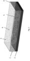
- Figure 1 shows a schematic of a coating, e.g. a multifunctional composite coating, according to the present disclosure.
- the present disclosure provides a coated article.
- the article can be, for example, an aircraft component, a propeller, or a gas turbine engine component.
- the article may be one suitable for use in a propelling system.
- the article may be a blade, for example a propeller blade or a fan blade.
- the coating may only be on a part of the article, for example on a particular surface or part of the surface of the article, or it may coat substantially all of the article or the surface of the article. Suitable locations on the article for the coating will be apparent to the skilled person and may be selected depending on the intended use of the article.
- the coating may cover substantially all of the surface of the blade, e.g. it may cover both sides of the blade.
- the coating of the present disclosure comprises a polymer matrix and the fillers described herein.
- the fillers may be dispersed throughout, or embedded in, the matrix.
- the fillers may be dispersed homogenously, or there may be a concentration gradient of one or more types of filler across the matrix or a region thereof. In some embodiments, all of the types of filler are dispersed homogenously throughout the matrix. In some embodiments, one or more of the filler types are dispersed homogenously throughout the matrix. In some embodiments, one or more of the filler types, for example the lamellar filler, are concentrated towards the article side of the coating, e.g. the inner surface of the coating. In some embodiments, one or more of the filler types is concentrated towards the side of the coating opposing the article, e.g. the outer surface of the coating.
- the coating thickness may be selected depending on the intended use of the article. In some embodiments, the thickness of the coating may vary across the coating, although it will typically be substantially uniform in thickness. Coating thicknesses may range from 0.5 to 750 ⁇ m, e.g. 1 to 500 ⁇ m, e.g. from 5 to 400 ⁇ m, from 10 to 300 ⁇ m, from 25 to 200 ⁇ m, from 50 to 100 ⁇ m.
- the polymer matrix can comprise, e.g. be formed of, a thermoset polymer or a thermoplastic polymer, i.e. the polymer matrix material may be or comprise a thermoset polymer or a thermoplastic polymer.
- suitable thermosets include: allyl resin, epoxy, melamine formaldehyde, phenol-formaldehyde plastic, polyester, vinyl ester, cyanate ester, polyimide, polyurethane, and silicone.
- thermoplastics examples include: polyacrylic acid, poly(methyl methacrylate), acrylonitrile butadiene styrene, polyamide, polylactic acid, polybenzimidazole, polycarbonate, polyether sulfone, polyalkenes (such as polyethylene and polypropylene), polyphenylene oxide, polyphenylene sulphide, polystyrene, polyvinyl chloride, polyvinylidene fluoride, fluoropolymer (e.g.
- polytetrafluoroethylene ethylene vinyl alcohol, liquid crystal polymer, polyacetal, polyacrylonitrile, polyamide-imide, polyaryletherketone, polybutadiene, polybutylene, polyketone, polyester, polyetheretherketone, polyetherimide, polyethersulfone, polyethylenechlorinates, polyimide, polymethylpentane, polysulfone, polyurethane, polyvinylidene chloride and thermoplastic elastomers. Mixtures or copolymers of any of these polymers may also be used as the polymer matrix material.
- the polymer matrix material may have a high hardness.
- the polymer matrix material may have a Rockwell hardness (e.g. on the B, C or M scale, typically M scale) of greater than or equal to 50, or greater than or equal to 60, or greater than or equal to 70, or greater than or equal to 80, or greater than or equal to 90, or greater than or equal to 100, or greater than or equal to 110, or greater than or equal to 120, or greater than or equal to 130, or greater than or equal to 140, or greater than or equal to 150.
- the polymer matrix may have a Shore D hardness of greater than or equal to 40, greater than or equal to 50, greater than or equal to 60, greater than or equal to 70, greater than or equal to 80, or greater than or equal to 90.
- the polymer may have a large strain at break, also known as elongation at break.
- the strain or elongation at break may be greater than or equal to 100%, or greater than or equal to 200%.
- the polymer matrix material may be present in the coating in an amount greater than or equal to 50 vol.% of the coating (i.e. at least 50 vol.%, e.g. 50 to 99 vol.% of the coating is matrix), greater than or equal to 60 vol.% of the coating, greater than or equal to 70 vol.% of the coating, greater than or equal to 80 vol.% of the coating, or greater than or equal to 90 vol.% of the coating, or greater than or equal to 95 vol.% of the coating.
- the volume fraction of polymer matrix material, in relation to the coating as a whole is up to and including 99 vol.%.
- the shape of the filler particles described herein may be defined in terms of aspect ratios.
- the primary aspect ratio refers to the ratio of the maximum dimension to the minimum dimension, i.e. the largest dimension divided by the smallest dimension, for example, the length (or width) of the particle divided by its thickness. This is often called the "length-to-thickness" aspect ratio.
- the smallest dimension for a rod-like particle will usually be the diameter or width of the cross-section, and the largest will be the length of the rod or fibre.
- Another aspect ratio which may be termed the secondary aspect ratio, can also be calculated by taking the ratio of the maximum, i.e. largest, dimension to the second largest dimension. For example, a rectangular sheet with a length of 200 ⁇ m, a width of 100 ⁇ m and a thickness of 1 ⁇ m would have a primary aspect ratio of 200 and a secondary aspect ratio of 2. For perfectly spherical particles, both aspect ratios are 1.
- the largest dimension is typically the length of the longest straight line which can be drawn across the particle. This may be taken to align with the longitudinal axis of the particle.
- the smallest dimension may be substantially perpendicular to the longitudinal axis (and therefore the largest dimension) and the second largest dimension may be substantially perpendicular to both the longitudinal axis (and therefore the largest dimension) and the smallest dimension.
- the largest dimension, the smallest dimension and the second largest dimension can be mutually perpendicular and arranged along or parallel to the x, y and z axes (i.e. the longitudinal, vertical and transverse axes), respectively, of a Cartesian coordinate system.
- particle sizes and aspect ratios may also relate to average, e.g. mean, particle dimensions.
- particle sizes for the largest dimension may refer to the average of the largest dimensions of the various particles.
- the particles used for each type of filler independently will be substantially uniform in shape and size.
- the average primary aspect ratio may be calculated by taking the ratio between the average of the largest dimensions of the various particles and the average of the smallest dimensions of the various particles. Alternatively the primary aspect ratio may be measured for each individual particle (or a selection of particles), and the sum of these aspect ratios divided by the total number of particles to provide an average primary aspect ratio.
- the average secondary aspect ratio may be calculated in similar ways, i.e. using the largest and second-largest dimensions.
- Particle sizes, dimensions (length, width and thickness or height) and aspect ratios (and therefore averages thereof) may be measured by methods known in the art, for example microscopy techniques such as optical microscopy, scanning electron microscopy (SEM), transmission electron microscopy (TEM), atomic force microscopy (AFM), or dynamic light scattering (DLS).
- SEM scanning electron microscopy
- TEM transmission electron microscopy
- AFM atomic force microscopy
- DLS dynamic light scattering
- each of the particles is imaged in top-down and side-on configuration.
- top-down refers to standard SEM configuration
- side-on imaging is achieved by placing the substrates in a perpendicular orientation at an angle of 5° with respect to normal.
- the top-down and side-on images are analysed using a suitable software package, such as ImageJ (National Institutes of Health) or AxioVision (Zeiss), to determine the particle dimensions, and these can then be used to deduce the primary and secondary aspect ratios.
- the coating comprises at least one inorganic filler.
- the inorganic filler may provide erosion resistance to the coating, thereby protecting the underlying article.
- the inorganic filler may therefore be an erosion-resistant filler.
- the inorganic filler may also fulfil other functions.
- the inorganic filler may have a specific hardness higher than or equal to 6 Mohs, or higher than or equal to 7 Mohs, or higher than or equal to 8 Mohs, or higher than or equal to 9 Mohs.
- the inorganic filler may be or comprise, for example, a ceramic material.
- the ceramic material may be or comprise a metal oxide, such as Al 2 O 3 , Cr 2 O 3 , Y 2 O 3 , ZrO 2 , CeO 2 , TiO 2 , Ta 2 O 5 , SiO 2 and TaO 2 , a metal nitride such as BN, TiN, ZrN, HfN, CrN, Si 3 N 4 , AIN, TiAIN, TiAICrN, TiCrN, TiZrN, a metal boride such as TiB 2 , ZrB 2 , Cr 3 B 2 , W 2 B 2 , AlB 2 , a metal carbide such as TaC, WC, TiC, SiC or B 4 C, a metal sulfide, such as MoS 2 , or combinations thereof.
- a metal oxide such as Al 2 O 3 , Cr 2 O 3 , Y 2 O 3 , ZrO 2 , CeO 2 , TiO 2 , Ta 2 O 5 , SiO 2 and TaO 2
- the inorganic filler may additionally or alternatively be or comprise a ceramic-metal composite (cermet), including for example a metal matrix composite.
- cermets include WC/Co, WCoCr, WC/Ni, TiC/Ni, TiC/Fe, Ni(Cr)/Cr 3 C 2 , TaC/Ni and combinations thereof.
- the inorganic filler may be or comprise SiC, SiO 2 or MoS 2 , or combinations thereof.
- Carbides such as silicon carbide (SiC) are particularly useful as an inorganic filler as not only can they improve erosion resistance but they can also improve conductivity, conferring antistatic functionality upon the coating. Many such carbides have the black colouration of carbon black.
- Sulphides such as molybdenum sulphide (MoS 2 ) can improve erosion resistance and conductivity and can confer hydrophobic properties upon the coating.
- MoS 2 molybdenum sulphide
- Oxides such as silicon dioxide (SiO 2 ) can impart erosion resistance and can also confer hydrophobic properties upon the coating.
- silicon carbide, molybdenum sulphide and silicon dioxide are used in combination as the inorganic filler.
- the inorganic filler may comprise approximately substantially spherical, e.g. spherical, rod-like or lamellar particles.
- the volume fraction of inorganic filler in relation to the coating as a whole may be lower than or equal to 20 vol.%, lower than or equal to 15 vol.%, lower than or equal to 10 vol.%, lower than or equal to 5 vol.%, or lower than or equal to 4 vol.%, or lower than or equal to 3 vol.%, or lower than or equal to 2 vol.%, or lower than or equal to 1 vol.% of the coating.
- values of lower than 5 vol.% may be most suitable.
- the volume fraction of inorganic filler in relation to the coating as a whole is at least 0.5 vol.%.
- the coating comprises at least one organic filler, e.g. a hydrophobic organic material.
- the organic filler may confer hydrophobicity on the surface of the coating, such that it provides a de-icing functionality. However, the organic filler may also fulfil other functions.
- the organic filler may be or comprise a polymer, e.g. a hydrophobic polymer.
- a hydrophobic polymer is a polymer that is relatively insoluble (e.g. not soluble) in water or other polar solvents.
- the polymer, e.g. hydrophobic polymer may be selected from the group consisting of acrylics, epoxies, polyalkenes (such as polyethylene and polypropylene), polystyrene, polyvinylchloride, polydimethylsiloxane, polyesters, poly(propylene) and fluoropolymers, and co-polymers thereof, in particular poly(propylene) (PP) and a fluoropolymer.
- Organic filler polymers may be added to the polymer matrix material to form a biphasic or polyphasic system, either as particles, e.g. in the form of polymer beads, or as a melt/solvent blended with the polymer matrix material.
- organic filler When the organic filler is included as particles, it can remain in particulate form in the final coating, or it can mix with the matrix polymer.
- the organic filler may be mixed with the matrix polymer, e.g. as liquid/melt.
- Polymer beads can be readily formed using methods known to the person skilled in the art or obtained from commercial suppliers.
- Organic fillers with a low surface energy can improve the hydrophobic behaviour of the coating because they lower the surface energy of the coating itself. This improvement in hydrophobicity limits water and ice build-up on the surface of the coating due to the lotus effect, thereby providing the coating with a de-icing functionality.
- the organic filler is homogenously distributed throughout the matrix polymer. In this way, the organic filler is present at the outer surface of the coating, i.e. the surface opposing the coated article, even if the coating is subjected to erosion.
- the organic filler is present on, or close to, the surface of the matrix. When the organic filer is located or positioned on or close to the surface of the matrix, it may impart hydrophobicity to the outer surface of the coating, i.e. the surface opposing the coated article.
- the organic filler is a polymer
- it is typically a different polymer to that of the matrix material.
- the organic filler may be present in an amount of up to and including 10 vol.%, or up to and including 5 vol.%, or up to and including 4 vol.%, or up to and including 3 vol.%, or up to and including 2 vol.%, or up to and including 1 vol.% of the coating.
- the volume fraction of organic filler in relation to the coating as a whole is at least 0.5 vol.%.
- the coating comprises at least one lamellar filler, e.g. a filler material which is in the form of sheets, flakes or platelets.
- Lamellar fillers are often referred to as 2D particles, as opposed to fibrous, tubular, rod-like, or fibre-like particles, which are typically considered 1D particles.
- the lamellar filler may therefore be a 2D filler.
- the lamellar filler material and/or particles may be made up of a layered material, i.e. a material which contains one or more layers stacked over one another, i.e. a series of thin layers, for example where each layer has a thickness of less than or equal to 10 nm, in particular around 1 nm.
- the lamellar fillers can thus also be termed "layered filler".
- the lamellar fillers can be in the form of sheets, flakes, ribbons or platelets.
- the lamellar filler may provide antistatic functionality to the coating, for example when the lamellar filler is conductive, e.g. has a conductivity of at least 10 -6 S.m -1 . Additionally or alternatively, the lamellar filler may fulfil the function of anti-corrosion.
- Lamellar materials can self-assemble in multilayer structures.
- lamellar filler particles may lie predominantly flat in or are aligned with the plane of the coating, e.g. their longest dimension may lie parallel to the surface of the article. In this way, the lamellar filler particles may lie in substantially the same plane as one another in the coating. This can permit only limited gas or moisture to permeate the structure.
- the layered structure formed by the lamellar filler in the matrix increases tortuosity which impedes small molecule diffusion through the coating.
- the layered structure also reduces crack propagation through the composite. Limited crack propagation in combination with the barrier effect results in less electrolyte diffusion to the expanded metal foil and therefore improved corrosion resistance, e.g. of any metal foil and of the underlying article.
- the lamellar filler may be in the form of particles.
- the lamellar filler particles e.g. flakes, sheets, ribbons or platelets
- the lamellar filler particles may have a primary aspect ratio of 50 to 1000, e.g. 100 to 900, for example 200 to 800, for example 300 to 700, for example 400 to 600, for example 450 to 500, and/or a secondary aspect ratio of 1 to 10, for example 1 to 5, for example 1 to 4, for example 1 to 3, for example 1 to 2, for example 1.
- the largest dimension of the particles of lamellar filler may be below or equal to 300 ⁇ m, for example below or equal to 250 ⁇ m, for example below or equal to 200 ⁇ m, for example below or equal to 150 ⁇ m, for example below or equal to 100 ⁇ m, for example below or equal to 50 ⁇ m.
- the largest dimension of the particles of lamellar filler is at least 0.5 ⁇ m.
- the largest dimension of the particles of lamellar filler is 0.5 - 300 ⁇ m, for example 1 - 250 ⁇ m, for example 5 - 200 ⁇ m, for example 10 - 150 ⁇ m, for example 10 - 100 ⁇ m, for example 1 - 50 ⁇ m.
- the second largest dimension of the particles of lamellar filler may be below or equal to 300 ⁇ m, for example below or equal to 250 ⁇ m, for example below or equal to 200 ⁇ m, for example below or equal to 150 ⁇ m, for example below or equal to 100 ⁇ m, for example below or equal to 50 ⁇ m, for example below or equal to 30 ⁇ m.
- the second largest dimension of the particles of lamellar filler is at least 0.5 ⁇ m.
- the second largest dimension of the particles of lamellar filler is 0.5 - 300 ⁇ m, for example 1 - 250 ⁇ m, for example 5 - 200 ⁇ m, for example 10 - 150 ⁇ m, for example 10 - 100 ⁇ m, for example 1 - 50 ⁇ m, for example 0.5 - 30 ⁇ m.
- the thickness (e.g. the smallest dimension) of the lamellar filler may be below or equal to 1 ⁇ m, for example 0.5 nm to 1 ⁇ m, or 0.5 nm to 500 nm, for example 0.5 nm to 100 nm or 10 nm to 100 nm.
- the lamellar filler may be present in a volume fraction of lower than or equal to 5%, or lower than or equal to 4%, or lower than or equal to 3%, or lower than or equal to 2%, or lower than or equal to 1% in the coating.
- the volume fraction of the lamellar filler in the coating may be in the range from 0.1 to 5 vol.%, e.g. 0.2 to 2 vol.%.
- the lamellar filler may be or comprise, e.g. may be in the form of, ceramic particles having a metal-oxide coating.
- the metal-oxide coating may be electrically conductive.
- ceramic particles for example mica, may be coated with a layer of antimony tin oxide (Sb:SnO 2 ) or antimony-doped tin oxide to provide electrical conductivity.
- layered particles are arranged in a layered structure down to the atomic level.
- the lamellar filler can be a carbon-based lamellar filler.
- the carbon-based lamellar fillers include graphene-based fillers, e.g. graphene, graphene oxide, reduced graphene oxide, graphene nanoplatelets, graphene nanoribbons and expanded graphite.
- the volume fraction of the carbon-based lamellar filler in the coating may be in the range from 0.1 to 5 vol.%, e.g. 0.2 to 2 vol.% or 0.5 to 1 vol.%.
- the presence of a carbon-based lamellar filler in the polymer matrix allows for conductivities of higher than or equal to 10 -6 S/m, which is sufficient to readily disperse electrostatic charges, thereby providing antistatic functionality to the coating.
- the lamellar filler may be or comprise a layered silicate, e.g. those made up of two-dimensional layers of fused silicate tetrahedral sheets.
- the sheets may be approximately 1 nm thick and 100 nm to 1000 nm long, and fused to an edge-shared octahedral sheet of metal atoms.
- layered silicates include montmorillonite, smectites, such as saponite, hectorite, fluorohectorite, fluoromica, kaolinite, magadiite, vermiculite and layered double hydroxides.
- the lamellar filler material may be or comprise a clay.
- the lamellar filler may be or comprise a layered phosphate.
- Layered phosphates have a similar structure to layered silicates, except the phosphate group replaces the silicate.
- An example of a layered phosphate is alpha-zirconium phosphate, which has the chemical formula of Zr(HPO 4 ) 2 .nH 2 O.
- Alpha-zirconium phosphate can be formed into nanoplatelets.
- Layered phosphates can also be formed from zinc phosphate and calcium phosphate.
- a coupling agent for example a silane-based additive
- a silane-based additive can be added to the coating, e.g. to the polymer matrix, to improve the compatibility of the fillers with the polymer matrix.
- Such agents may also control the organisation of the fillers throughout the polymer matrix, i.e. they may influence the location and/or orientation of each type of filler.
- this improvement is obtained because one part of the silane-based additive has good affinity with the matrix, and the other part has good affinity with the fillers.
- silane-based additive is a polysilane.
- Polysilanes are organosilicon compounds with the formula (R 2 Si) n , where R can be a group such as amine, alkyl, alkoxy, aryl and alkenyl, either substituted or unsubstituted.
- R can be a group such as amine, alkyl, alkoxy, aryl and alkenyl, either substituted or unsubstituted.
- silane-based additive may be or comprise a glycidyl based organosilane.
- amino-silanes and their derivatives such as amine-terminated polysiloxane, and/or epoxy terminated silanes.
- Specific examples include (3-glycidyloxypropyl)trimethoxysilane, (3-aminopropyl)trimethoxysilane, (3-aminopropyl)triethoxysilane, and poly(dimethylsiloxane), bis(3-aminopropyl) terminated.
- the coupling agent e.g. silane-based additive
- the coupling agent may have a volume fraction of at least 0.1 %.
- lamellar in terms of particle shape is intended to encompass "flat" filler particles, i.e. those in which one dimension is substantially smaller than the other two dimensions (or two are substantially larger than one), such as sheets, flakes, ribbons or platelets. Such fillers or particles are often referred to as 2D fillers or particles, due to one dimension being substantially smaller than the other two.
- 1D fillers or particles is a term used for those in which one dimension is substantially larger than the other two dimensions. Fibrous, tubular, rod-like, or fibre-like particles are commonly known as 1D particles.
- Figure 1 shows a specific example of the coating according to the present disclosure.
- the coating (1) is disposed on an article (2), but other layers may be present between the coating (1) and the article (2), such as an expanded metal foil layer, a glass fabric layer, and/or a layer of primer and/or anti-corrosion paint.
- Spherical SiC, SiO 2 and MoS 2 particles are present as the inorganic filler (3) and are dispersed throughout the polymer matrix (4), which contains a silane-based additive.
- Lamellar fillers (5) such as graphene nanoplatelets are present and have self-assembled to form a layer towards the base of the polymer matrix (i.e. closest to the substrate), while polymer beads (such as beads of poly(propylene) and/or fluoropolymer, e.g. poly(tetrafluoroethylene)) as organic fillers (6) are present throughout the polymer matrix.
- the combination of fillers described herein provides a multifunctional coating which avoids the need for multiple layers and the associated costs and manufacturing complexity.
- the coating of the present disclosure may therefore be viewed, or referred to, as a composite coating, e.g. a multi-functional composite coating.
- the present disclosure provides a composite coating/layer which can eliminate the need for multiple interlayers, thus resulting in a smaller or lighter final product (e.g. the coated article). Elimination of the multiple interlayers also achieves cost savings due to the time and cost of applying multiple interlayers being avoided. Moreover, poor adhesion between various layers is a drawback of the currently used methods. In particular, adhesion failures at the interface between layers is a problem. The reduction in layers achievable by the present disclosure therefore reduces the likelihood of failure of the article. It will be appreciated that in aerospace applications, failure of the component may represent a significant safety hazard.
- the functionalities of the fillers and their contribution to the overall properties of the coating described herein may be related to the nature of the fillers, their shape and the organisation of the fillers in the matrix (e.g. the way in which the fillers are dispersed throughout the matrix). The latter may be related to a filler's surface area in contact with the matrix.
- the lamellar fillers may improve fatigue performance via a stick slip mechanism which increases toughness and dampening.
- the inorganic fillers can provide anti-erosion and antistatic functionality
- the organic fillers can provide de-icing functionality
- the lamellar filler can provide anti-static and anti-corrosion functionality.
- Combinations and configurations of the present disclosure can have a synergistic effect.
- the multifunctional nature of the coating exhibits advantages such as reduced weight, costs savings and increased simplicity of manufacture.
- the coating of the present disclosure is typically the outermost layer, i.e. it is exposed to air.
- other layers may be present between the article, e.g. the propeller or fan blade, and the coating of the present disclosure.
- the article may be coated with a metal layer, e.g. metal film, expanded metal foil or mesh layer, for example aluminium, copper, bronze, nickel, gold, or titanium, in particular aluminium.
- a metal layer e.g. metal film, expanded metal foil or mesh layer, for example aluminium, copper, bronze, nickel, gold, or titanium, in particular aluminium.
- a metal layer may be located between the surface of the article and the coating of the present disclosure.
- the metal layer because of its antistatic properties, is able to offer protection against lightning strikes.
- a further optional layer is a layer of glass fabric which, when present, is typically applied on the surface of the metal layer opposite the article. This layer may serve to insulate the metal layer from other coatings, e.g. from the coating of the present disclosure.
- a layer of primer and/or anti-corrosion paint may be applied to the glass fabric. This may provide added corrosion protection, e.g. to the metal layer. Primer may be used to improve adhesion of any subsequently deposited layers.
- the coating of the present disclosure there are no layers between the article surface and the coating of the present disclosure, i.e. the coating of the present disclosure is located on the surface of the article.
- the coated article consists of the article and the coating herein described.
- the coating described herein forms the outermost surface of the coated article.
- further coatings or layers are provided on the surface of the coating, i.e. the coating as described herein is not the outermost surface of the coated article.
- the coating may be applied using methods known to those skilled in the art.
- the present disclosure thus also provides a method of preparing a coated article, e.g. as described herein, said method comprising providing an article and coating at least a part of said article with a coating as herein described.
- the coating step may be performed by spraying. Any suitable spraying method, such as spray painting, may be used. Suitable spraying methods include air gun spraying (e.g. high volume low pressure or low volume low pressure) and airless gun spraying. Spray painting can be performed using a spray gun or an airbrush.
- a spray gun used in air gun spraying has one or more nozzles, triggers, feedstock basins which contain feedstock (i.e. the material to be sprayed) and an air compressor.
- feedstock i.e. the material to be sprayed
- an air compressor When the trigger is activated, the feedstock in the basin mixes with compressed air and generates a fine spray which can be directed at a substrate via the nozzle.
- the coating can be applied using an airless spray gun.
- an airless spray gun the material to be applied as a coating is atomized by being subjected to a high pressure, and the atomized material is ejected via a nozzle at high pressure towards a substrate.
- the coating may also be applied by painting.
- the coating is applied by depositing, e.g. spraying, the components of the coating, either individually or in combination, onto a surface of the article. This deposition is typically performed at room temperature.
- the polymer matrix may be applied either as the polymer matrix material itself, or as a precursor thereto, i.e. a precursor to the polymer that forms the coating's matrix (the polymer matrix material).
- polymer matrix material precursor is a plurality of monomers or a monomer composition, which may include a mixture of different monomers.
- suitable polymer matrix material precursors include polyepoxides mixed with a hardener such as polyfunctional amines, acids (and acid anhydrides), phenols, alcohols and thiols.
- suitable polymer matrix material precursors include isocyanates mixed with one or more polyols.
- suitable polymer matrix material precursors include polyols such as glycols including ethylene glycol, propylene glycol, and diethylene glycol mixed with acids such as phthalic acid, isophthalic acid, terephthalic acid, and maleic anhydride.
- the polymer matrix is applied as the polymer matrix material itself, it may be dissolved in a suitable solvent, in which case it is the solution of polymer matrix material which is applied to the surface of the article.
- suitable solvents will be known to the person skilled in the art and include ketones, such as butanone, also known as methyl ethyl ketone (MEK), alcohols, such as ethanol and butanol, and glycol ethers, such as 2-butoxyethanol, and combinations thereof.
- Suitable solvents which may be used additionally or alternatively to those mentioned above include mineral spirits, turpentine, naphtha, toluene, dimethylformamide (DMF), ethylbenzene, xylene, n-butyl acetate, and combinations thereof.
- mineral spirits turpentine, naphtha, toluene, dimethylformamide (DMF), ethylbenzene, xylene, n-butyl acetate, and combinations thereof.
- DMF dimethylformamide
- ethylbenzene ethylbenzene
- xylene xylene
- n-butyl acetate n-butyl acetate
- a polymer film may be obtained after evaporation/removal of the solvent, e.g. by the application of heat.
- the matrix material may be polymerised and/or cured. Curing can be accelerated by heating, e.g. by using an oven. The exact conditions used for curing vary depending on the selected polymer matrix material, and would be known to the person skilled in the art.
- one or more of the fillers are mixed with the polymer matrix material or precursor, and the resulting mixture applied to the article to form the coating. In this way, a coating in which the fillers are homogenously distributed throughout the matrix can be obtained.
- the method as described herein comprises providing an article; coating said article with a polymer matrix material or precursor thereto in which an inorganic filler, an organic filler and a lamellar filler have been dispersed (e.g. by mixing); e.g. to form a coating as described herein (on the article).
- the method optionally comprises polymerizing and/or curing said precursor.
- the coating comprises the fillers dispersed or embedded in the polymer matrix.
- lamellar filler particles e.g. flakes, platelets or sheet-like particles
- the lamellar filler particles may intrinsically self-arrange in the layer such that they lie predominantly flat in, i.e. are aligned with, the plane of the coating.
- the self-assembly process may be improved by the use of the coupling agents described herein.
- a first layer of polymer matrix material or precursor thereto could be applied to the article, e.g. by air gun spraying or painting, and then one or more of the fillers could be applied to the first polymer/precursor layer, and then further polymer/precursor applied over the one or more fillers. Further fillers could then be applied, followed by further applications of polymer/precursor until the desired coating is formed.
- the polymer precursor can then be polymerized, e.g. by curing. In this way, the fillers will be embedded in the resultant polymer matrix.
- the polymer/precursor may be applied using an air spray gun or an airbrush, and the fillers by an airless spray gun.
- the method as described herein comprises: providing an article; coating said article with a polymer matrix material or precursor thereto; depositing one or more fillers as herein described onto the polymer matrix material or precursor thereto; and depositing a further layer of polymer matrix material or precursor thereto. Further fillers may then be deposited (e.g. until the coating contains at least one of each type of filler), optionally followed by a further layer of polymer/precursor.
- the polymer/precursor may be polymerised and/or cured as appropriate, either following one or more of the deposition steps, or as a final step.
- the fillers may be applied in a different order to above, or two or more may be applied together.
- the inorganic filler may be applied before the organic filler. If a coupling agent is used, this may be applied as the fillers are (i.e. at the same time and/or via the same method), or may be combined with the polymer matrix material (or its precursor) prior to deposition.
- the matrix polymer precursor may be polymerized by curing.
- a coated article produced by a method as herein described forms a further aspect of the present disclosure.
- references to "comprises” and/or “comprising,” should be understood to also encompass “consist(s) of”, “consisting of”, “consist(s) essentially of” and “consisting essentially of”.
Abstract
The present disclosure provides a coated article, comprising: an article, and a coating applied to at least a part of said article, wherein said coating comprises a polymer matrix material, an inorganic filler, an organic filler, and a lamellar filler, and a method of preparing the same.
Description
- The present disclosure relates to a multi-functional composite coating, for example one for use in propelling systems, gas turbine engines, or aeronautical applications, in particular on propeller blades, and a method for preparing an article coated with said coating.
- Objects exposed to extreme environments, e.g. in conditions of high temperature and/or pressure, typically require some form of protection in order to have a useful life of an acceptable, e.g. in terms of cost or safety, duration. This is often achieved by the use of coatings. The protective properties of such coatings can be enhanced by the use of additives or fillers dispersed or embedded therein. For example, hard materials can be used to provide erosion resistance, and conductive fillers can be used to protect against high voltage events.
- Extreme environments are encountered frequently in the aeronautical industry. For example, aeroplanes and their components are exposed to extremes of temperature and pressure. This is particularly true of components such as turbine blades in a gas turbine engine and propellers.
- Propellers are often used in aeronautical applications. Propellers are formed of a hub and blades. The hub is rotated by means of a power source, and this movement of the hub causes the blades to spin. In modern aircraft, the rate of rotation is typically very high. This means that the propeller, and in particular the blades, are subjected to extremes of temperature and pressure when in use. Lightning strikes are also a problem when flying. Exposure to such harsh conditions can cause damage to the propeller blade, reducing its useful life.
- For these reasons, articles such as propeller blades need to be protected. This is typically achieved by applying various coatings or layers to the article such as an anti-corrosion paint layer, and/or an anti-erosion topcoat. Other layers may also be present between the topcoat and the article, such as a glass fabric insulating layer and/or a metal foil, e.g. an expanded metal foil, (or metal grid/mesh) layer.
- The topcoat usually contains fillers. Typically, a hard material such as silicon oxide is used as one of the fillers, as it protects the structure from erosion, while carbon black is used as an anti-static filler which helps to dissipate electrostatic build-up from air friction.
- However, there can be problems with the conventional coatings. For example, even where there is a glass fabric insulating layer and an anti-corrosion paint layer between the topcoat and the expanded metal foil, galvanic corrosion can occur between the foil and the carbon black found in the topcoat. This can result in surface blistering, which can in turn reduce the integrity of the composite protective structure formed on the blade, thereby reducing its lifetime.
- The present disclosure provides an alternative coating for an article which eliminates the above problem. Furthermore, because of the presence of additional fillers in the coating of the present disclosure, it is able to provide additional useful functionality, such as de-icing, without substantially increasing the weight of the article.
- Viewed from a first aspect, the present disclosure provides a coated article comprising: an article, and a coating applied to at least a part of said article, wherein said coating comprises a polymer matrix material, an inorganic filler, an organic filler, and a lamellar filler.
- The coating of the present disclosure may be viewed as a layer disposed upon the article, e.g. a layer of polymer matrix material comprising the fillers described herein, i.e. an inorganic filler; an organic filler; and a lamellar filler. Similarly, the coated article may be viewed as an article with the layer disposed on at least part of the article's surface. The present disclosure also provides an article coated with the coating described herein.
- The article may be an aircraft component, a propeller, or a gas turbine engine component, for example a blade, for example a propeller blade or a fan blade.
- The polymer matrix material may be or comprise a thermoset or a thermoplastic polymer (e.g. a polyurethane or epoxy polymer) or combinations or co-polymers thereof.
- The polymer matrix material may have a Rockwell hardness on the B, C or M scale, e.g. M scale, of greater than or equal to 50, or greater than or equal to 60, or greater than or equal to 70, or greater than or equal to 80, or greater than or equal to 90, or greater than or equal to 100, or greater than or equal to 110, or greater than or equal to 120, or greater than or equal to 130, or greater than or equal to 140, or greater than or equal to 150.
- The polymer matrix material may be present in an amount of greater than or equal to 50 vol.% of the coating (i.e. at least 50 vol.% of the coating is polymer matrix material), greater than or equal to 60 vol.% of the coating, greater than or equal to 70 vol.% of the coating, greater than or equal to 80 vol.% of the coating, or greater than or equal to 90 vol.% of the coating, or greater than or equal to 95 vol.% of the coating. In some embodiments, the volume fraction of polymer matrix material, in relation to the coating as a whole, is up to and including 99 vol.%.
- The inorganic filler may have a specific hardness higher than or equal to 6 Mohs, e.g. higher than or equal to 8 Mohs.
- The inorganic filler may be present in the coating in a volume fraction of up to and including 20%, or up to and including 15%, or up to and including 10%, or up to and including 5%, or up to and including 4%, or up to and including 3%, or up to and including 2%, or up to and including 1%. In some embodiments, the volume fraction of inorganic filler in relation to the coating as a whole is at least 0.5 vol.%.
- The inorganic filler may be or comprise a ceramic material. The inorganic filler may be or comprise a metal oxide, a metal nitride, a metal boride, a metal carbide, a metal sulfide, or a ceramic metal composite, or combinations thereof. The inorganic filler may be or comprise a ceramic metal composite. The inorganic filler may be or comprise silicon oxide, silicon nitride and/or silicon carbide.
- The inorganic filler may be in the form of particles, i.e. it may be in particulate form when added to the coating and/or may be present in the final coating in particulate form, e.g. as particles dispersed throughout the polymer matrix. The inorganic filler may be in the form of spherical particles, lamellar particles or rod-like particles. The inorganic filler may be or comprise ceramic particles.
- The inorganic filler particles may be or comprise substantially spherical particles, e.g. spherical particles.
- The inorganic filler particles may have a lamellar (e.g. flake-like) shape.
- The inorganic filler particles may have a rod-like or fibrous shape (e.g. they may be fibres or filaments).
- The particles (e.g. the spherical or substantially spherical particles) may have a primary (and optionally also secondary) aspect ratio of 20 or less, e.g. 1 to 20, 10 or less, e.g. 1 to 10, 5 or less, e.g. 1 to 5, or 1 to 2, e.g. around 1.
- The inorganic filler particles (e.g. the lamellar inorganic filler particles) may have a primary aspect ratio of 100 or less, for example 90 or less, for example 80 or less, for example 70 or less, for example 60 or less. Exemplary ranges of primary aspect ratio include 2-100, 3-90, 4-80, 5-70 and 10-60.
- The inorganic filler particles (e.g. the rod-like or fibrous inorganic particles) may have a primary aspect ratio of greater than or equal to 20, for example greater than or equal to 30, for example greater than or equal to 40, for example greater than or equal to 50. Exemplary ranges of primary aspect ratio include 20-1000, 30-500, 40-200 and 50-100.
- The inorganic filler particles may have a primary aspect ratio of 1-1000, or 5-1000, e.g. 10-500 or 10-100, for example 20-70, 30-60 or 40-50.
- Inorganic filler particle size may be selected according to the article to be coated. Typical particle sizes for the smallest dimension are 0.5 nm to 2 µm, e.g. 1 nm to 1 µm, or 2 nm to 0.5 µm. Typical particle sizes for the largest dimension are 0.5 to 200 µm, e.g. 1 to 100 µm, or 2 to 50 µm.
- The inorganic filler may be or comprise SiC, SiO2, MoS2 or combinations thereof.
- The organic filler may be or comprise a polymer, for example a hydrophobic polymer, e.g. selected from the group consisting of acrylics, epoxies, polyalkenes (such as polyethylene and polypropylene), polystyrene, polyvinylchloride, polydimethylsiloxane, polyesters, and fluoropolymers, e.g. poly(tetrafluoroethylene).
- The organic filler may be or comprise poly(propylene) or a fluoropolymer, e.g. poly(tetrafluoroethylene).
- The organic filler may be in the form of polymer beads or particles. The organic filler may be in particulate form when added to the coating and/or may be present in the final coating in particulate form, e.g. dispersed as particles throughout the polymer matrix.
- The organic filler particles may be substantially spherical particles, e.g. spherical particles.
- The organic filler particles may have a lamellar (e.g. flake-like) shape.
- The organic filler particles may have a rod-like or fibrous shape (e.g. they may be fibres or filaments).
- The particles (e.g. the spherical or substantially spherical particles) may have a primary (and optionally, also secondary) aspect ratio of 20 or less, e.g. 1 to 20, 10 or less, e.g. 1 to 10, 5 or less, e.g. 1 to 5 or 1 to 2, e.g. around 1.
- The organic filler particles (e.g. the lamellar organic filler particles) may have a primary aspect ratio of 100 or less, for example 90 or less, for example 80 or less, for example 70 or less, for example 60 or less. Exemplary ranges of primary aspect ratio include 2-100, 3-90, 4-80, 5-70 and 10-60.
- The organic filler particles (e.g. the rod-like or fibrous inorganic particles) may have a primary aspect ratio of greater than or equal to 20, for example greater than or equal to 30, for example, greater than or equal to 40, for example greater than or equal to 50. Exemplary ranges of primary aspect ratio include 20-1000, 30-500, 40-200 and 50-100.
- The organic filler particles may have a primary aspect ratio of 1-1000 or 5-1000, e.g. 10-500 or 10-100, for example 20-70, 30-60 or 40-50.
- Organic filler particle (e.g. polymer bead) size may be selected according to the article to be coated. The organic filler particles have a smallest dimension and a largest dimension. Typical particle sizes for the smallest dimension are 0.5 nm to 2 µm, e.g. 1 nm to 1 µm, or 2 nm to 0.5 µm. Typical particle sizes for the largest dimension are 0.5 to 200 µm, e.g. 1 to 100 µm, or 2 to 50 µm.
- The lamellar filler may be or comprise a carbon-based lamellar filler (such as graphene nanoplatelets), ceramic particles having a metal-oxide coating, a layered silicate, a layered phosphate, or combinations thereof.
- The lamellar filler may be or comprise a carbon-based lamellar filler present in a volume fraction of from 0.2 to 5 vol.%, e.g. 0.2 to 2.0 vol.%, of the coating.
- The coating, e.g. the polymer matrix thereof, may further comprise a coupling agent such as a silane-based additive. Such an additive may be mixed or blended with the polymer matrix material.
- The inorganic filler may be or comprise silicon carbide, the organic filler may be or comprise poly(propylene) or a fluoropolymer, and the lamellar filler may be or comprise graphene nanoplatelets.
- In another aspect, the present disclosure provides a method of preparing a coated article, e.g. one as described herein, said method comprising providing an article and coating at least a part of said article with a coating as defined herein.
- The method may comprise coating the article with a polymer matrix material or precursor thereto in which an inorganic filler, an organic filler and a lamellar filler have been dispersed, and, optionally, polymerizing and/or curing said polymer precursor.
- The method may comprise coating the article with a polymer matrix material or precursor thereto, depositing one or more fillers selected from an inorganic filler, an organic filler, and a lamellar filler onto the polymer matrix material or precursor thereto, depositing a further layer of polymer matrix material or precursor thereto, and, optionally, polymerizing and/or curing said polymer precursor.
- It will be readily appreciated by the skilled person that the various optional and preferred features of the disclosure as described above may be applicable to all the various aspects of the disclosure discussed. For example, features disclosed in connection with the article may be applicable to the method, and vice versa.
- Certain preferred aspects of the present disclosure will now be described in greater detail, by way of example only and with reference to the accompanying drawing, in which:
Figure 1 shows a schematic of a coating, e.g. a multifunctional composite coating, according to the present disclosure. - The present disclosure provides a coated article. The article can be, for example, an aircraft component, a propeller, or a gas turbine engine component. The article may be one suitable for use in a propelling system. The article may be a blade, for example a propeller blade or a fan blade. The coating may only be on a part of the article, for example on a particular surface or part of the surface of the article, or it may coat substantially all of the article or the surface of the article. Suitable locations on the article for the coating will be apparent to the skilled person and may be selected depending on the intended use of the article. Typically, the coating may cover substantially all of the surface of the blade, e.g. it may cover both sides of the blade.
- The coating of the present disclosure comprises a polymer matrix and the fillers described herein. The fillers may be dispersed throughout, or embedded in, the matrix. The fillers may be dispersed homogenously, or there may be a concentration gradient of one or more types of filler across the matrix or a region thereof. In some embodiments, all of the types of filler are dispersed homogenously throughout the matrix. In some embodiments, one or more of the filler types are dispersed homogenously throughout the matrix. In some embodiments, one or more of the filler types, for example the lamellar filler, are concentrated towards the article side of the coating, e.g. the inner surface of the coating. In some embodiments, one or more of the filler types is concentrated towards the side of the coating opposing the article, e.g. the outer surface of the coating.
- The coating thickness may be selected depending on the intended use of the article. In some embodiments, the thickness of the coating may vary across the coating, although it will typically be substantially uniform in thickness. Coating thicknesses may range from 0.5 to 750 µm, e.g. 1 to 500 µm, e.g. from 5 to 400 µm, from 10 to 300 µm, from 25 to 200 µm, from 50 to 100 µm.
- The polymer matrix can comprise, e.g. be formed of, a thermoset polymer or a thermoplastic polymer, i.e. the polymer matrix material may be or comprise a thermoset polymer or a thermoplastic polymer. Examples of suitable thermosets include: allyl resin, epoxy, melamine formaldehyde, phenol-formaldehyde plastic, polyester, vinyl ester, cyanate ester, polyimide, polyurethane, and silicone. Examples of suitable thermoplastics include: polyacrylic acid, poly(methyl methacrylate), acrylonitrile butadiene styrene, polyamide, polylactic acid, polybenzimidazole, polycarbonate, polyether sulfone, polyalkenes (such as polyethylene and polypropylene), polyphenylene oxide, polyphenylene sulphide, polystyrene, polyvinyl chloride, polyvinylidene fluoride, fluoropolymer (e.g. polytetrafluoroethylene), ethylene vinyl alcohol, liquid crystal polymer, polyacetal, polyacrylonitrile, polyamide-imide, polyaryletherketone, polybutadiene, polybutylene, polyketone, polyester, polyetheretherketone, polyetherimide, polyethersulfone, polyethylenechlorinates, polyimide, polymethylpentane, polysulfone, polyurethane, polyvinylidene chloride and thermoplastic elastomers. Mixtures or copolymers of any of these polymers may also be used as the polymer matrix material.
- The polymer matrix material may have a high hardness. Typically, the polymer matrix material may have a Rockwell hardness (e.g. on the B, C or M scale, typically M scale) of greater than or equal to 50, or greater than or equal to 60, or greater than or equal to 70, or greater than or equal to 80, or greater than or equal to 90, or greater than or equal to 100, or greater than or equal to 110, or greater than or equal to 120, or greater than or equal to 130, or greater than or equal to 140, or greater than or equal to 150. The polymer matrix may have a Shore D hardness of greater than or equal to 40, greater than or equal to 50, greater than or equal to 60, greater than or equal to 70, greater than or equal to 80, or greater than or equal to 90.
- The polymer may have a large strain at break, also known as elongation at break. The strain or elongation at break may be greater than or equal to 100%, or greater than or equal to 200%.
- The polymer matrix material may be present in the coating in an amount greater than or equal to 50 vol.% of the coating (i.e. at least 50 vol.%, e.g. 50 to 99 vol.% of the coating is matrix), greater than or equal to 60 vol.% of the coating, greater than or equal to 70 vol.% of the coating, greater than or equal to 80 vol.% of the coating, or greater than or equal to 90 vol.% of the coating, or greater than or equal to 95 vol.% of the coating. In some embodiments, the volume fraction of polymer matrix material, in relation to the coating as a whole, is up to and including 99 vol.%.
- The shape of the filler particles described herein may be defined in terms of aspect ratios. In this context, the primary aspect ratio refers to the ratio of the maximum dimension to the minimum dimension, i.e. the largest dimension divided by the smallest dimension, for example, the length (or width) of the particle divided by its thickness. This is often called the "length-to-thickness" aspect ratio. For example, the smallest dimension for a rod-like particle will usually be the diameter or width of the cross-section, and the largest will be the length of the rod or fibre.
- Another aspect ratio, which may be termed the secondary aspect ratio, can also be calculated by taking the ratio of the maximum, i.e. largest, dimension to the second largest dimension. For example, a rectangular sheet with a length of 200 µm, a width of 100 µm and a thickness of 1 µm would have a primary aspect ratio of 200 and a secondary aspect ratio of 2. For perfectly spherical particles, both aspect ratios are 1.
- The largest dimension is typically the length of the longest straight line which can be drawn across the particle. This may be taken to align with the longitudinal axis of the particle. The smallest dimension may be substantially perpendicular to the longitudinal axis (and therefore the largest dimension) and the second largest dimension may be substantially perpendicular to both the longitudinal axis (and therefore the largest dimension) and the smallest dimension. In other words, the largest dimension, the smallest dimension and the second largest dimension can be mutually perpendicular and arranged along or parallel to the x, y and z axes (i.e. the longitudinal, vertical and transverse axes), respectively, of a Cartesian coordinate system.
- As there will be some particle size variation within a sample of particulate materials, the particle sizes and aspect ratios (both primary and secondary) mentioned herein may also relate to average, e.g. mean, particle dimensions. Thus, particle sizes for the largest dimension may refer to the average of the largest dimensions of the various particles. Typically, the particles used for each type of filler independently will be substantially uniform in shape and size.
- The average primary aspect ratio may be calculated by taking the ratio between the average of the largest dimensions of the various particles and the average of the smallest dimensions of the various particles. Alternatively the primary aspect ratio may be measured for each individual particle (or a selection of particles), and the sum of these aspect ratios divided by the total number of particles to provide an average primary aspect ratio. The average secondary aspect ratio may be calculated in similar ways, i.e. using the largest and second-largest dimensions.
- Particle sizes, dimensions (length, width and thickness or height) and aspect ratios (and therefore averages thereof) may be measured by methods known in the art, for example microscopy techniques such as optical microscopy, scanning electron microscopy (SEM), transmission electron microscopy (TEM), atomic force microscopy (AFM), or dynamic light scattering (DLS). An exemplary SEM method which is suitable for use in the present disclosure is described in Daniel P. Veghte & Miriam Arak Freedman (2014) Facile Method for Determining the Aspect Ratios of Mineral Dust Aerosol by Electron Microscopy, Aerosol Science and Technology, 48:7, 715-724, DOI: 10.1080/02786826.2014.920484. In such a measurement method, each of the particles is imaged in top-down and side-on configuration. In this context, top-down refers to standard SEM configuration, and side-on imaging is achieved by placing the substrates in a perpendicular orientation at an angle of 5° with respect to normal. The top-down and side-on images are analysed using a suitable software package, such as ImageJ (National Institutes of Health) or AxioVision (Zeiss), to determine the particle dimensions, and these can then be used to deduce the primary and secondary aspect ratios.
- The coating comprises at least one inorganic filler. The inorganic filler may provide erosion resistance to the coating, thereby protecting the underlying article. The inorganic filler may therefore be an erosion-resistant filler. However, the inorganic filler may also fulfil other functions. The inorganic filler may have a specific hardness higher than or equal to 6 Mohs, or higher than or equal to 7 Mohs, or higher than or equal to 8 Mohs, or higher than or equal to 9 Mohs. The inorganic filler may be or comprise, for example, a ceramic material. The ceramic material may be or comprise a metal oxide, such as Al2O3, Cr2O3, Y2O3, ZrO2, CeO2, TiO2, Ta2O5, SiO2 and TaO2, a metal nitride such as BN, TiN, ZrN, HfN, CrN, Si3N4, AIN, TiAIN, TiAICrN, TiCrN, TiZrN, a metal boride such as TiB2, ZrB2, Cr3B2, W2B2, AlB2, a metal carbide such as TaC, WC, TiC, SiC or B4C, a metal sulfide, such as MoS2, or combinations thereof. The inorganic filler may additionally or alternatively be or comprise a ceramic-metal composite (cermet), including for example a metal matrix composite. Examples of cermets include WC/Co, WCoCr, WC/Ni, TiC/Ni, TiC/Fe, Ni(Cr)/Cr3C2, TaC/Ni and combinations thereof. In particular, the inorganic filler may be or comprise SiC, SiO2 or MoS2, or combinations thereof.
- Carbides such as silicon carbide (SiC) are particularly useful as an inorganic filler as not only can they improve erosion resistance but they can also improve conductivity, conferring antistatic functionality upon the coating. Many such carbides have the black colouration of carbon black.
- Sulphides such as molybdenum sulphide (MoS2) can improve erosion resistance and conductivity and can confer hydrophobic properties upon the coating.
- Oxides such as silicon dioxide (SiO2) can impart erosion resistance and can also confer hydrophobic properties upon the coating.
- In one embodiment, silicon carbide, molybdenum sulphide and silicon dioxide are used in combination as the inorganic filler.
- As described herein, the inorganic filler may comprise approximately substantially spherical, e.g. spherical, rod-like or lamellar particles.
- The volume fraction of inorganic filler in relation to the coating as a whole may be lower than or equal to 20 vol.%, lower than or equal to 15 vol.%, lower than or equal to 10 vol.%, lower than or equal to 5 vol.%, or lower than or equal to 4 vol.%, or lower than or equal to 3 vol.%, or lower than or equal to 2 vol.%, or lower than or equal to 1 vol.% of the coating. In some embodiments, to prevent embrittlement of the composite, i.e. the coating as herein described, values of lower than 5 vol.% may be most suitable. In some embodiments, the volume fraction of inorganic filler in relation to the coating as a whole is at least 0.5 vol.%.
- The coating comprises at least one organic filler, e.g. a hydrophobic organic material. The organic filler may confer hydrophobicity on the surface of the coating, such that it provides a de-icing functionality. However, the organic filler may also fulfil other functions.
- The organic filler may be or comprise a polymer, e.g. a hydrophobic polymer. A hydrophobic polymer is a polymer that is relatively insoluble (e.g. not soluble) in water or other polar solvents. The polymer, e.g. hydrophobic polymer, may be selected from the group consisting of acrylics, epoxies, polyalkenes (such as polyethylene and polypropylene), polystyrene, polyvinylchloride, polydimethylsiloxane, polyesters, poly(propylene) and fluoropolymers, and co-polymers thereof, in particular poly(propylene) (PP) and a fluoropolymer. Organic filler polymers may be added to the polymer matrix material to form a biphasic or polyphasic system, either as particles, e.g. in the form of polymer beads, or as a melt/solvent blended with the polymer matrix material.
- When the organic filler is included as particles, it can remain in particulate form in the final coating, or it can mix with the matrix polymer.
- The organic filler may be mixed with the matrix polymer, e.g. as liquid/melt.
- Polymer beads can be readily formed using methods known to the person skilled in the art or obtained from commercial suppliers.
- Organic fillers with a low surface energy can improve the hydrophobic behaviour of the coating because they lower the surface energy of the coating itself. This improvement in hydrophobicity limits water and ice build-up on the surface of the coating due to the lotus effect, thereby providing the coating with a de-icing functionality. In some embodiments, the organic filler is homogenously distributed throughout the matrix polymer. In this way, the organic filler is present at the outer surface of the coating, i.e. the surface opposing the coated article, even if the coating is subjected to erosion. In some embodiments, the organic filler is present on, or close to, the surface of the matrix. When the organic filer is located or positioned on or close to the surface of the matrix, it may impart hydrophobicity to the outer surface of the coating, i.e. the surface opposing the coated article.
- When the organic filler is a polymer, it is typically a different polymer to that of the matrix material.
- The organic filler may be present in an amount of up to and including 10 vol.%, or up to and including 5 vol.%, or up to and including 4 vol.%, or up to and including 3 vol.%, or up to and including 2 vol.%, or up to and including 1 vol.% of the coating. In some embodiments, the volume fraction of organic filler in relation to the coating as a whole is at least 0.5 vol.%.
- The coating comprises at least one lamellar filler, e.g. a filler material which is in the form of sheets, flakes or platelets. Lamellar fillers are often referred to as 2D particles, as opposed to fibrous, tubular, rod-like, or fibre-like particles, which are typically considered 1D particles. The lamellar filler may therefore be a 2D filler.
- The lamellar filler material and/or particles may be made up of a layered material, i.e. a material which contains one or more layers stacked over one another, i.e. a series of thin layers, for example where each layer has a thickness of less than or equal to 10 nm, in particular around 1 nm. The lamellar fillers can thus also be termed "layered filler".
- The lamellar fillers can be in the form of sheets, flakes, ribbons or platelets.
- The lamellar filler may provide antistatic functionality to the coating, for example when the lamellar filler is conductive, e.g. has a conductivity of at least 10-6S.m-1. Additionally or alternatively, the lamellar filler may fulfil the function of anti-corrosion.
- Lamellar materials can self-assemble in multilayer structures. In the context of the coating described herein, lamellar filler particles may lie predominantly flat in or are aligned with the plane of the coating, e.g. their longest dimension may lie parallel to the surface of the article. In this way, the lamellar filler particles may lie in substantially the same plane as one another in the coating. This can permit only limited gas or moisture to permeate the structure. The layered structure formed by the lamellar filler in the matrix increases tortuosity which impedes small molecule diffusion through the coating. The layered structure also reduces crack propagation through the composite. Limited crack propagation in combination with the barrier effect results in less electrolyte diffusion to the expanded metal foil and therefore improved corrosion resistance, e.g. of any metal foil and of the underlying article.
- The lamellar filler may be in the form of particles. The lamellar filler particles (e.g. flakes, sheets, ribbons or platelets) may have a primary aspect ratio of 50 to 1000, e.g. 100 to 900, for example 200 to 800, for example 300 to 700, for example 400 to 600, for example 450 to 500, and/or a secondary aspect ratio of 1 to 10, for example 1 to 5, for example 1 to 4, for example 1 to 3, for example 1 to 2, for example 1.
- The largest dimension of the particles of lamellar filler, typically the length, may be below or equal to 300 µm, for example below or equal to 250 µm, for example below or equal to 200 µm, for example below or equal to 150 µm, for example below or equal to 100 µm, for example below or equal to 50 µm. In some embodiments, the largest dimension of the particles of lamellar filler is at least 0.5 µm. In some embodiments, the largest dimension of the particles of lamellar filler is 0.5 - 300 µm, for example 1 - 250 µm, for example 5 - 200 µm, for example 10 - 150 µm, for example 10 - 100 µm, for example 1 - 50 µm.
- The second largest dimension of the particles of lamellar filler, typically the width, may be below or equal to 300 µm, for example below or equal to 250 µm, for example below or equal to 200 µm, for example below or equal to 150 µm, for example below or equal to 100 µm, for example below or equal to 50 µm, for example below or equal to 30 µm. In some embodiments, the second largest dimension of the particles of lamellar filler is at least 0.5 µm. In some embodiments, the second largest dimension of the particles of lamellar filler is 0.5 - 300 µm, for example 1 - 250 µm, for example 5 - 200 µm, for example 10 - 150 µm, for example 10 - 100 µm, for example 1 - 50 µm, for example 0.5 - 30 µm.
- The thickness (e.g. the smallest dimension) of the lamellar filler may be below or equal to 1 µm, for example 0.5 nm to 1 µm, or 0.5 nm to 500 nm, for example 0.5 nm to 100 nm or 10 nm to 100 nm.
- The lamellar filler may be present in a volume fraction of lower than or equal to 5%, or lower than or equal to 4%, or lower than or equal to 3%, or lower than or equal to 2%, or lower than or equal to 1% in the coating. For example, the volume fraction of the lamellar filler in the coating may be in the range from 0.1 to 5 vol.%, e.g. 0.2 to 2 vol.%.
- The lamellar filler may be or comprise, e.g. may be in the form of, ceramic particles having a metal-oxide coating. The metal-oxide coating may be electrically conductive. For example, ceramic particles, for example mica, may be coated with a layer of antimony tin oxide (Sb:SnO2) or antimony-doped tin oxide to provide electrical conductivity.
- Materials such as graphene, layered silicate and layered phosphates which constitute atomically thin layers are particularly effective lamellar fillers due to their large primary aspect ratio, low permeability, and surface chemistry. In some embodiments, layered particles are arranged in a layered structure down to the atomic level.
- The lamellar filler can be a carbon-based lamellar filler. Examples of the carbon-based lamellar fillers include graphene-based fillers, e.g. graphene, graphene oxide, reduced graphene oxide, graphene nanoplatelets, graphene nanoribbons and expanded graphite. The volume fraction of the carbon-based lamellar filler in the coating may be in the range from 0.1 to 5 vol.%, e.g. 0.2 to 2 vol.% or 0.5 to 1 vol.%. The presence of a carbon-based lamellar filler in the polymer matrix allows for conductivities of higher than or equal to 10-6 S/m, which is sufficient to readily disperse electrostatic charges, thereby providing antistatic functionality to the coating.
- The lamellar filler may be or comprise a layered silicate, e.g. those made up of two-dimensional layers of fused silicate tetrahedral sheets. The sheets may be approximately 1 nm thick and 100 nm to 1000 nm long, and fused to an edge-shared octahedral sheet of metal atoms. Examples of layered silicates include montmorillonite, smectites, such as saponite, hectorite, fluorohectorite, fluoromica, kaolinite, magadiite, vermiculite and layered double hydroxides. The lamellar filler material may be or comprise a clay.
- The lamellar filler may be or comprise a layered phosphate. Layered phosphates have a similar structure to layered silicates, except the phosphate group replaces the silicate. An example of a layered phosphate is alpha-zirconium phosphate, which has the chemical formula of Zr(HPO4)2.nH2O. Alpha-zirconium phosphate can be formed into nanoplatelets. Layered phosphates can also be formed from zinc phosphate and calcium phosphate.
- A coupling agent, for example a silane-based additive, can be added to the coating, e.g. to the polymer matrix, to improve the compatibility of the fillers with the polymer matrix. Such agents may also control the organisation of the fillers throughout the polymer matrix, i.e. they may influence the location and/or orientation of each type of filler. In the case of silane-based additives, this improvement is obtained because one part of the silane-based additive has good affinity with the matrix, and the other part has good affinity with the fillers.
- An example of a silane-based additive is a polysilane. Polysilanes are organosilicon compounds with the formula (R2Si)n, where R can be a group such as amine, alkyl, alkoxy, aryl and alkenyl, either substituted or unsubstituted. Another example of a silane-based additive is silane compounds with the formula SiR4, where R can be a group such as amine, alkyl, alkoxy, aryl and alkenyl, either substituted or unsubstituted. For example, where the polymer matrix is epoxy-based, the silane-based additive may be or comprise a glycidyl based organosilane. Other examples include amino-silanes and their derivatives, such as amine-terminated polysiloxane, and/or epoxy terminated silanes. Specific examples include (3-glycidyloxypropyl)trimethoxysilane, (3-aminopropyl)trimethoxysilane, (3-aminopropyl)triethoxysilane, and poly(dimethylsiloxane), bis(3-aminopropyl) terminated.
- The coupling agent, e.g. silane-based additive, may have a volume fraction of lower than or equal to 5%, or lower than or equal to 4%, or lower than or equal to 3%, or lower than or equal to 2%, or lower than or equal to 1% in the coating. In some embodiments, the coupling agent may have a volume fraction of at least 0.1 %.
- The term "lamellar" in terms of particle shape is intended to encompass "flat" filler particles, i.e. those in which one dimension is substantially smaller than the other two dimensions (or two are substantially larger than one), such as sheets, flakes, ribbons or platelets. Such fillers or particles are often referred to as 2D fillers or particles, due to one dimension being substantially smaller than the other two.
- 1D fillers or particles is a term used for those in which one dimension is substantially larger than the other two dimensions. Fibrous, tubular, rod-like, or fibre-like particles are commonly known as 1D particles.
-
Figure 1 shows a specific example of the coating according to the present disclosure. In this example, the coating (1) is disposed on an article (2), but other layers may be present between the coating (1) and the article (2), such as an expanded metal foil layer, a glass fabric layer, and/or a layer of primer and/or anti-corrosion paint. Spherical SiC, SiO2 and MoS2 particles are present as the inorganic filler (3) and are dispersed throughout the polymer matrix (4), which contains a silane-based additive. Lamellar fillers (5) such as graphene nanoplatelets are present and have self-assembled to form a layer towards the base of the polymer matrix (i.e. closest to the substrate), while polymer beads (such as beads of poly(propylene) and/or fluoropolymer, e.g. poly(tetrafluoroethylene)) as organic fillers (6) are present throughout the polymer matrix. - The combination of fillers described herein provides a multifunctional coating which avoids the need for multiple layers and the associated costs and manufacturing complexity. The coating of the present disclosure may therefore be viewed, or referred to, as a composite coating, e.g. a multi-functional composite coating.
- In contrast to coating systems which incorporate multiple layers, the present disclosure provides a composite coating/layer which can eliminate the need for multiple interlayers, thus resulting in a smaller or lighter final product (e.g. the coated article). Elimination of the multiple interlayers also achieves cost savings due to the time and cost of applying multiple interlayers being avoided. Moreover, poor adhesion between various layers is a drawback of the currently used methods. In particular, adhesion failures at the interface between layers is a problem. The reduction in layers achievable by the present disclosure therefore reduces the likelihood of failure of the article. It will be appreciated that in aerospace applications, failure of the component may represent a significant safety hazard.
- Without wishing to be bound by theory, the functionalities of the fillers and their contribution to the overall properties of the coating described herein may be related to the nature of the fillers, their shape and the organisation of the fillers in the matrix (e.g. the way in which the fillers are dispersed throughout the matrix). The latter may be related to a filler's surface area in contact with the matrix.
- The lamellar fillers may improve fatigue performance via a stick slip mechanism which increases toughness and dampening. The inorganic fillers can provide anti-erosion and antistatic functionality, the organic fillers can provide de-icing functionality, and the lamellar filler can provide anti-static and anti-corrosion functionality. Combinations and configurations of the present disclosure can have a synergistic effect. The multifunctional nature of the coating exhibits advantages such as reduced weight, costs savings and increased simplicity of manufacture.
- While further coatings may be applied on top of the coating of the present disclosure, the coating of the present disclosure is typically the outermost layer, i.e. it is exposed to air. As mentioned above in the context of the specific example of
Figure 1 , but which applies more generally to the present disclosure, other layers may be present between the article, e.g. the propeller or fan blade, and the coating of the present disclosure. - For example, the article may be coated with a metal layer, e.g. metal film, expanded metal foil or mesh layer, for example aluminium, copper, bronze, nickel, gold, or titanium, in particular aluminium. Such a metal layer may be located between the surface of the article and the coating of the present disclosure. The metal layer, because of its antistatic properties, is able to offer protection against lightning strikes.
- A further optional layer is a layer of glass fabric which, when present, is typically applied on the surface of the metal layer opposite the article. This layer may serve to insulate the metal layer from other coatings, e.g. from the coating of the present disclosure.
- A layer of primer and/or anti-corrosion paint may be applied to the glass fabric. This may provide added corrosion protection, e.g. to the metal layer. Primer may be used to improve adhesion of any subsequently deposited layers.
- In certain embodiments, there are no layers between the article surface and the coating of the present disclosure, i.e. the coating of the present disclosure is located on the surface of the article. In some embodiments, the coated article consists of the article and the coating herein described. In some embodiments, the coating described herein forms the outermost surface of the coated article. In certain embodiments, further coatings or layers are provided on the surface of the coating, i.e. the coating as described herein is not the outermost surface of the coated article.
- The coating may be applied using methods known to those skilled in the art. The present disclosure thus also provides a method of preparing a coated article, e.g. as described herein, said method comprising providing an article and coating at least a part of said article with a coating as herein described.
- The coating step may be performed by spraying. Any suitable spraying method, such as spray painting, may be used. Suitable spraying methods include air gun spraying (e.g. high volume low pressure or low volume low pressure) and airless gun spraying. Spray painting can be performed using a spray gun or an airbrush.
- A spray gun used in air gun spraying has one or more nozzles, triggers, feedstock basins which contain feedstock (i.e. the material to be sprayed) and an air compressor. When the trigger is activated, the feedstock in the basin mixes with compressed air and generates a fine spray which can be directed at a substrate via the nozzle.
- Alternatively, the coating can be applied using an airless spray gun. In an airless spray gun, the material to be applied as a coating is atomized by being subjected to a high pressure, and the atomized material is ejected via a nozzle at high pressure towards a substrate.
- The coating may also be applied by painting.
- In an embodiment, the coating is applied by depositing, e.g. spraying, the components of the coating, either individually or in combination, onto a surface of the article. This deposition is typically performed at room temperature.
- The polymer matrix may be applied either as the polymer matrix material itself, or as a precursor thereto, i.e. a precursor to the polymer that forms the coating's matrix (the polymer matrix material).
- An example of a polymer matrix material precursor is a plurality of monomers or a monomer composition, which may include a mixture of different monomers. Where the polymer matrix material is an epoxy polymer, suitable polymer matrix material precursors include polyepoxides mixed with a hardener such as polyfunctional amines, acids (and acid anhydrides), phenols, alcohols and thiols. Where the polymer matrix material is polyurethane, suitable polymer matrix material precursors include isocyanates mixed with one or more polyols. Where the polymer matrix material is unsaturated polyester, suitable polymer matrix material precursors include polyols such as glycols including ethylene glycol, propylene glycol, and diethylene glycol mixed with acids such as phthalic acid, isophthalic acid, terephthalic acid, and maleic anhydride.
- Where the polymer matrix is applied as the polymer matrix material itself, it may be dissolved in a suitable solvent, in which case it is the solution of polymer matrix material which is applied to the surface of the article. Suitable solvents will be known to the person skilled in the art and include ketones, such as butanone, also known as methyl ethyl ketone (MEK), alcohols, such as ethanol and butanol, and glycol ethers, such as 2-butoxyethanol, and combinations thereof. Other examples of suitable solvents which may be used additionally or alternatively to those mentioned above include mineral spirits, turpentine, naphtha, toluene, dimethylformamide (DMF), ethylbenzene, xylene, n-butyl acetate, and combinations thereof.
- A polymer film may be obtained after evaporation/removal of the solvent, e.g. by the application of heat. After deposition, the matrix material may be polymerised and/or cured. Curing can be accelerated by heating, e.g. by using an oven. The exact conditions used for curing vary depending on the selected polymer matrix material, and would be known to the person skilled in the art.
- In one embodiment, one or more of the fillers are mixed with the polymer matrix material or precursor, and the resulting mixture applied to the article to form the coating. In this way, a coating in which the fillers are homogenously distributed throughout the matrix can be obtained.
- In some embodiments, the method as described herein comprises providing an article; coating said article with a polymer matrix material or precursor thereto in which an inorganic filler, an organic filler and a lamellar filler have been dispersed (e.g. by mixing); e.g. to form a coating as described herein (on the article). The method optionally comprises polymerizing and/or curing said precursor. The coating comprises the fillers dispersed or embedded in the polymer matrix.
- In some embodiments, lamellar filler particles, e.g. flakes, platelets or sheet-like particles, are dispersed in the polymer matrix material or precursor prior to application. Once this mixture comprising lamellar filler particles dispersed in the matrix polymer precursor is applied to the article, the lamellar filler particles may intrinsically self-arrange in the layer such that they lie predominantly flat in, i.e. are aligned with, the plane of the coating. The self-assembly process may be improved by the use of the coupling agents described herein.
- In some embodiments, a first layer of polymer matrix material or precursor thereto could be applied to the article, e.g. by air gun spraying or painting, and then one or more of the fillers could be applied to the first polymer/precursor layer, and then further polymer/precursor applied over the one or more fillers. Further fillers could then be applied, followed by further applications of polymer/precursor until the desired coating is formed. The polymer precursor can then be polymerized, e.g. by curing. In this way, the fillers will be embedded in the resultant polymer matrix. In particular, the polymer/precursor may be applied using an air spray gun or an airbrush, and the fillers by an airless spray gun.
- In some embodiments, the method as described herein comprises: providing an article; coating said article with a polymer matrix material or precursor thereto; depositing one or more fillers as herein described onto the polymer matrix material or precursor thereto; and depositing a further layer of polymer matrix material or precursor thereto. Further fillers may then be deposited (e.g. until the coating contains at least one of each type of filler), optionally followed by a further layer of polymer/precursor. The polymer/precursor may be polymerised and/or cured as appropriate, either following one or more of the deposition steps, or as a final step.
- When the fillers are applied sequentially, the order of steps may be as follows:
- (a) apply matrix polymer/precursor (to the article)
- (b) apply lamellar filler
- (c) apply matrix polymer/precursor
- (d) apply organic filler
- (e) apply matrix polymer/precursor
- (f) apply inorganic filler
- (g) apply matrix polymer/precursor
- (h) cure and/or polymerise the matrix polymer/precursor.
- The fillers may be applied in a different order to above, or two or more may be applied together. For example, the inorganic filler may be applied before the organic filler. If a coupling agent is used, this may be applied as the fillers are (i.e. at the same time and/or via the same method), or may be combined with the polymer matrix material (or its precursor) prior to deposition.
- The matrix polymer precursor may be polymerized by curing.
- A coated article produced by a method as herein described forms a further aspect of the present disclosure.
- References to "comprises" and/or "comprising," should be understood to also encompass "consist(s) of", "consisting of", "consist(s) essentially of" and "consisting essentially of".
- The terminology used herein is for the purpose of describing particular embodiments only and is not intended to be limiting of the present disclosure. As used herein, the singular forms "a", "an" and "the" are intended to include the plural forms as well, unless the context clearly indicates otherwise. It will be further understood that the terms "comprises" and/or "comprising," when used in this specification, specify the presence of stated features, integers, steps, operations, elements, and/or components, but do not preclude the presence or addition of one or more other features, integers, steps, operations, element components, and/or groups thereof.
- It will be readily appreciated by the skilled person that the various optional and preferred features of the disclosure as described above may be applicable to all the various aspects of the disclosure discussed.
- While the present disclosure has been described with reference to an exemplary embodiment or embodiments, it will be understood by those skilled in the art that various changes may be made and equivalents may be substituted for elements thereof without departing from the scope of the present disclosure. In addition, many modifications may be made to adapt a particular situation or material to the teachings of the present disclosure without departing from the essential scope thereof. Therefore, it is intended that the present disclosure not be limited to the particular embodiment disclosed as the best mode contemplated for carrying out this present disclosure, but that the present disclosure will include all embodiments falling within the scope of the claims.
Claims (15)
- A coated article, comprising:an article; anda coating applied to at least a part of said article;
wherein said coating comprises:a polymer matrix material;an inorganic filler;an organic filler; anda lamellar filler. - The coated article of claim 1, wherein the article is an aircraft component.
- The coated article of claim 1 or claim 2, wherein the polymer matrix material is a thermoset or a thermoplastic polymer.
- The coated article of any one of the preceding claims, wherein the polymer matrix material has a Rockwell hardness on the M scale of greater than or equal to 50.
- The coated article of any one of the preceding claims, wherein the inorganic filler has a specific hardness higher than or equal to 6 Mohs.
- The coated article of any one of the preceding claims, wherein the inorganic filler is ceramic particles.
- The coated article of any one of the preceding claims, wherein the inorganic filler is SiC, SiO2, MoS2 or combinations thereof.
- The coated article of any one of the preceding claims, wherein the organic filler is a hydrophobic polymer.
- The coated article of any one of the preceding claims, wherein the organic filler is in the form of polymer beads.
- The coated article of any one of the preceding claims, wherein the lamellar filler is or comprises a carbon-based lamellar filler, ceramic particles having a metal-oxide coating, a layered silicate, a layered phosphate, or combinations thereof.
- The coated article of any one of the preceding claims, wherein the coating, e.g. the polymer matrix thereof, further comprises a silane-based additive.
- The coated article of any one of the preceding claims, wherein the inorganic filler is or comprises silicon carbide, the organic filler is or comprises poly(propylene) or a fluoropolymer, and the lamellar filler is or comprises graphene nanoplatelets.
- A method of preparing a coated article, e.g. one according to any one of claims 1-12, said method comprising:providing an article; andcoating at least a part of said article with a coating as defined in any preceding claim.
- The method of claim 13, said method comprising:providing an article;coating said article with a polymer matrix material or precursor thereto in which an inorganic filler, an organic filler and a lamellar filler have been dispersed; and, optionally,polymerizing and/or curing said polymer precursor.
- The method of claim 13, said method comprising:providing an article;coating said article with a polymer matrix material or precursor thereto;depositing one or more fillers selected from an inorganic filler; an organic filler; and a lamellar filler onto the polymer matrix material or precursor thereto;depositing a further layer of polymer matrix material or precursor thereto; and, optionally, polymerizing and/or curing said polymer precursor.
Priority Applications (2)
| Application Number | Priority Date | Filing Date | Title |
|---|---|---|---|
| EP21306346.4A EP4159819A1 (en) | 2021-09-29 | 2021-09-29 | Multi-functional composite coating |
| PCT/EP2022/077031 WO2023052459A1 (en) | 2021-09-29 | 2022-09-28 | Multi-functional composite coating |
Applications Claiming Priority (1)
| Application Number | Priority Date | Filing Date | Title |
|---|---|---|---|
| EP21306346.4A EP4159819A1 (en) | 2021-09-29 | 2021-09-29 | Multi-functional composite coating |
Publications (1)
| Publication Number | Publication Date |
|---|---|
| EP4159819A1 true EP4159819A1 (en) | 2023-04-05 |
Family
ID=78483227
Family Applications (1)
| Application Number | Title | Priority Date | Filing Date |
|---|---|---|---|
| EP21306346.4A Withdrawn EP4159819A1 (en) | 2021-09-29 | 2021-09-29 | Multi-functional composite coating |
Country Status (2)
| Country | Link |
|---|---|
| EP (1) | EP4159819A1 (en) |
| WO (1) | WO2023052459A1 (en) |
Citations (6)
| Publication number | Priority date | Publication date | Assignee | Title |
|---|---|---|---|---|
| EP2363429A1 (en) * | 2006-03-10 | 2011-09-07 | Goodrich Corporation | Low density lightining strike protection for use in airplanes |
| US20120045954A1 (en) * | 2008-10-07 | 2012-02-23 | Ross Technology Corporation | Highly durable superhydrophobic. oleophobic and anti-icing coatings and methods and compositions for their preparation |
| US20140329729A1 (en) * | 2011-12-21 | 2014-11-06 | Leibniz-Institut Fuer Neue Materialien Gemeinnuetzige Gmbh | Pigmented, Fine-Structured, Tribological Composite Material |
| EP3266526A1 (en) * | 2013-06-24 | 2018-01-10 | The Boeing Company | Methods for delaying ice formation and coating compositions |
| US20200071547A1 (en) * | 2017-03-22 | 2020-03-05 | Kübler Lubrication München SE & Co. KG | Dry film lubricants containing graphene |
| US20200223556A1 (en) * | 2019-01-10 | 2020-07-16 | The Boeing Company | Protective coatings for turbine blades and methods |
-
2021
- 2021-09-29 EP EP21306346.4A patent/EP4159819A1/en not_active Withdrawn
-
2022
- 2022-09-28 WO PCT/EP2022/077031 patent/WO2023052459A1/en unknown
Patent Citations (6)
| Publication number | Priority date | Publication date | Assignee | Title |
|---|---|---|---|---|
| EP2363429A1 (en) * | 2006-03-10 | 2011-09-07 | Goodrich Corporation | Low density lightining strike protection for use in airplanes |
| US20120045954A1 (en) * | 2008-10-07 | 2012-02-23 | Ross Technology Corporation | Highly durable superhydrophobic. oleophobic and anti-icing coatings and methods and compositions for their preparation |
| US20140329729A1 (en) * | 2011-12-21 | 2014-11-06 | Leibniz-Institut Fuer Neue Materialien Gemeinnuetzige Gmbh | Pigmented, Fine-Structured, Tribological Composite Material |
| EP3266526A1 (en) * | 2013-06-24 | 2018-01-10 | The Boeing Company | Methods for delaying ice formation and coating compositions |
| US20200071547A1 (en) * | 2017-03-22 | 2020-03-05 | Kübler Lubrication München SE & Co. KG | Dry film lubricants containing graphene |
| US20200223556A1 (en) * | 2019-01-10 | 2020-07-16 | The Boeing Company | Protective coatings for turbine blades and methods |
Non-Patent Citations (1)
| Title |
|---|
| DANIEL P. VEGHTEMIRIAM ARAK FREEDMAN: "Facile Method for Determining the Aspect Ratios of Mineral Dust Aerosol by Electron Microscopy", AEROSOL SCIENCE AND TECHNOLOGY, vol. 48, no. 7, 2014, pages 715 - 724 |
Also Published As
| Publication number | Publication date |
|---|---|
| WO2023052459A1 (en) | 2023-04-06 |
Similar Documents
| Publication | Publication Date | Title |
|---|---|---|
| US9676965B2 (en) | Composite article having protective coating | |
| EP2333025B1 (en) | Articles comprising a weather resistant silicone coating | |
| Verma et al. | Preparation of hydrophobic epoxy–polydimethylsiloxane–graphene oxide nanocomposite coatings for antifouling application | |
| CN104508056A (en) | Tunable materials | |
| WO2004065474A1 (en) | Coating composition containing surface treated clay mixture, the surface treated clay mixture used therefor, and methods of their use | |
| CN113785019B (en) | Control of cure rate using polyether synergists | |
| Kareem et al. | Electrical and thermal characteristics of MWCNTs modified carbon fiber/epoxy composite films | |
| EP3006590B1 (en) | Thermal spray for durable and lage-area hydrophobic and superhydrophobic/icephobic coatings | |
| EP3023248B1 (en) | Carbon-based barrier coatings for high-temperature polymer-matrix composites | |
| EP3758924A1 (en) | A method of manufacturing an object from a composite material and an object formed thereby | |
| WO2010129032A1 (en) | Barrier coatings post-treated with multi-valent metal cations | |
| EP4159819A1 (en) | Multi-functional composite coating | |
| EP3783071A1 (en) | Electrically conductive coating compositions with corrosion resistance | |
| Peng | Polyurethane nanocomposite coatings for aeronautical applications | |
| JP5716192B2 (en) | Forms for objects other than flying objects or windmills | |
| WO2009038971A1 (en) | Erosion resistant impregnating resin systems and composites | |
| CN111732869B (en) | Composition for resisting atomic oxygen denudation and preparation method and application thereof | |
| JP2007331157A (en) | Gas barrier film laminate | |
| Berger et al. | Organo-functional Silane | |
| WO2023209379A1 (en) | Chemical resistance | |
| JPH0693406A (en) | Flame retardant material | |
| US20230323155A1 (en) | Multi-functional silizane-based coatings and materials | |
| Hu et al. | Preparation of Inorganic Filler Modified Epoxy Resin Adhesive and Study on Its Compatibility with UDMH | |
| KR20220029351A (en) | Method for forming high heat resistant coating film using liquid ceramic composition and high heat resistant coating film prepared thereby | |
| WO2023150439A1 (en) | In-mold coating compositions and uses thereof |
Legal Events
| Date | Code | Title | Description |
|---|---|---|---|
| PUAI | Public reference made under article 153(3) epc to a published international application that has entered the european phase |
Free format text: ORIGINAL CODE: 0009012 |
|
| STAA | Information on the status of an ep patent application or granted ep patent |
Free format text: STATUS: THE APPLICATION HAS BEEN PUBLISHED |
|
| AK | Designated contracting states |
Kind code of ref document: A1 Designated state(s): AL AT BE BG CH CY CZ DE DK EE ES FI FR GB GR HR HU IE IS IT LI LT LU LV MC MK MT NL NO PL PT RO RS SE SI SK SM TR |
|
| STAA | Information on the status of an ep patent application or granted ep patent |
Free format text: STATUS: THE APPLICATION IS DEEMED TO BE WITHDRAWN |
|
| 18D | Application deemed to be withdrawn |
Effective date: 20231006 |