EP3006590B1 - Thermal spray for durable and lage-area hydrophobic and superhydrophobic/icephobic coatings - Google Patents
Thermal spray for durable and lage-area hydrophobic and superhydrophobic/icephobic coatings Download PDFInfo
- Publication number
- EP3006590B1 EP3006590B1 EP15185897.4A EP15185897A EP3006590B1 EP 3006590 B1 EP3006590 B1 EP 3006590B1 EP 15185897 A EP15185897 A EP 15185897A EP 3006590 B1 EP3006590 B1 EP 3006590B1
- Authority
- EP
- European Patent Office
- Prior art keywords
- coating
- particles
- thermal spray
- hydrophobic
- coating precursor
- Prior art date
- Legal status (The legal status is an assumption and is not a legal conclusion. Google has not performed a legal analysis and makes no representation as to the accuracy of the status listed.)
- Active
Links
- 238000000576 coating method Methods 0.000 title claims description 241
- 230000002209 hydrophobic effect Effects 0.000 title claims description 127
- 239000007921 spray Substances 0.000 title claims description 61
- 230000003075 superhydrophobic effect Effects 0.000 title description 29
- 239000011248 coating agent Substances 0.000 claims description 189
- 239000002245 particle Substances 0.000 claims description 137
- 239000000758 substrate Substances 0.000 claims description 79
- 239000002243 precursor Substances 0.000 claims description 73
- 238000000034 method Methods 0.000 claims description 70
- 239000011163 secondary particle Substances 0.000 claims description 31
- 239000010410 layer Substances 0.000 claims description 28
- 238000009718 spray deposition Methods 0.000 claims description 25
- 239000001301 oxygen Substances 0.000 claims description 20
- 229910052760 oxygen Inorganic materials 0.000 claims description 20
- 239000000843 powder Substances 0.000 claims description 19
- 230000003746 surface roughness Effects 0.000 claims description 18
- 238000010438 heat treatment Methods 0.000 claims description 15
- 229920000642 polymer Polymers 0.000 claims description 15
- 239000000126 substance Substances 0.000 claims description 14
- 239000000446 fuel Substances 0.000 claims description 13
- QVGXLLKOCUKJST-UHFFFAOYSA-N atomic oxygen Chemical compound [O] QVGXLLKOCUKJST-UHFFFAOYSA-N 0.000 claims description 11
- 239000002131 composite material Substances 0.000 claims description 10
- 230000000717 retained effect Effects 0.000 claims description 9
- 239000002184 metal Substances 0.000 claims description 8
- 229910052751 metal Inorganic materials 0.000 claims description 8
- 229910001092 metal group alloy Inorganic materials 0.000 claims description 6
- 239000000919 ceramic Substances 0.000 claims description 4
- 150000002739 metals Chemical class 0.000 claims description 4
- 239000002356 single layer Substances 0.000 claims description 4
- 239000007789 gas Substances 0.000 claims description 3
- 238000007749 high velocity oxygen fuel spraying Methods 0.000 claims description 2
- 239000004696 Poly ether ether ketone Substances 0.000 description 48
- 229920002530 polyetherether ketone Polymers 0.000 description 48
- XLYOFNOQVPJJNP-UHFFFAOYSA-N water Substances O XLYOFNOQVPJJNP-UHFFFAOYSA-N 0.000 description 26
- 239000000203 mixture Substances 0.000 description 24
- 235000019592 roughness Nutrition 0.000 description 22
- 230000008018 melting Effects 0.000 description 19
- 238000002844 melting Methods 0.000 description 19
- 229920001343 polytetrafluoroethylene Polymers 0.000 description 18
- 230000001965 increasing effect Effects 0.000 description 8
- 229910000831 Steel Inorganic materials 0.000 description 7
- 239000010959 steel Substances 0.000 description 7
- 238000007751 thermal spraying Methods 0.000 description 7
- 238000000151 deposition Methods 0.000 description 6
- 239000010935 stainless steel Substances 0.000 description 6
- 229910001220 stainless steel Inorganic materials 0.000 description 6
- 238000005516 engineering process Methods 0.000 description 5
- RYGMFSIKBFXOCR-UHFFFAOYSA-N Copper Chemical compound [Cu] RYGMFSIKBFXOCR-UHFFFAOYSA-N 0.000 description 4
- 229910052802 copper Inorganic materials 0.000 description 4
- 239000010949 copper Substances 0.000 description 4
- 230000008021 deposition Effects 0.000 description 4
- 230000000694 effects Effects 0.000 description 4
- 230000000670 limiting effect Effects 0.000 description 4
- 239000000463 material Substances 0.000 description 4
- 239000002105 nanoparticle Substances 0.000 description 4
- OKTJSMMVPCPJKN-UHFFFAOYSA-N Carbon Chemical compound [C] OKTJSMMVPCPJKN-UHFFFAOYSA-N 0.000 description 3
- 230000008901 benefit Effects 0.000 description 3
- 238000002485 combustion reaction Methods 0.000 description 3
- 230000005661 hydrophobic surface Effects 0.000 description 3
- 238000007788 roughening Methods 0.000 description 3
- 238000011282 treatment Methods 0.000 description 3
- 101000878595 Arabidopsis thaliana Squalene synthase 1 Proteins 0.000 description 2
- 230000003373 anti-fouling effect Effects 0.000 description 2
- 230000003115 biocidal effect Effects 0.000 description 2
- 238000010276 construction Methods 0.000 description 2
- 230000003247 decreasing effect Effects 0.000 description 2
- 230000007123 defense Effects 0.000 description 2
- 230000002708 enhancing effect Effects 0.000 description 2
- 238000005530 etching Methods 0.000 description 2
- 229910002804 graphite Inorganic materials 0.000 description 2
- 239000010439 graphite Substances 0.000 description 2
- 229920006258 high performance thermoplastic Polymers 0.000 description 2
- 238000005259 measurement Methods 0.000 description 2
- 239000002923 metal particle Substances 0.000 description 2
- 230000003287 optical effect Effects 0.000 description 2
- -1 poly(tetrafluoroethylene) Polymers 0.000 description 2
- 239000004810 polytetrafluoroethylene Substances 0.000 description 2
- 239000005348 self-cleaning glass Substances 0.000 description 2
- 239000002904 solvent Substances 0.000 description 2
- 238000009736 wetting Methods 0.000 description 2
- 229910001209 Low-carbon steel Inorganic materials 0.000 description 1
- XOJVVFBFDXDTEG-UHFFFAOYSA-N Norphytane Natural products CC(C)CCCC(C)CCCC(C)CCCC(C)C XOJVVFBFDXDTEG-UHFFFAOYSA-N 0.000 description 1
- 239000003929 acidic solution Substances 0.000 description 1
- 239000000853 adhesive Substances 0.000 description 1
- 230000001070 adhesive effect Effects 0.000 description 1
- 239000000443 aerosol Substances 0.000 description 1
- 230000032683 aging Effects 0.000 description 1
- 238000004458 analytical method Methods 0.000 description 1
- 238000000137 annealing Methods 0.000 description 1
- 239000012300 argon atmosphere Substances 0.000 description 1
- 239000011230 binding agent Substances 0.000 description 1
- 230000015572 biosynthetic process Effects 0.000 description 1
- 238000005422 blasting Methods 0.000 description 1
- 229910052799 carbon Inorganic materials 0.000 description 1
- 239000006229 carbon black Substances 0.000 description 1
- 239000011195 cermet Substances 0.000 description 1
- 238000004140 cleaning Methods 0.000 description 1
- 239000011247 coating layer Substances 0.000 description 1
- 238000004891 communication Methods 0.000 description 1
- 230000001276 controlling effect Effects 0.000 description 1
- 230000002596 correlated effect Effects 0.000 description 1
- 238000005260 corrosion Methods 0.000 description 1
- 230000007797 corrosion Effects 0.000 description 1
- 238000005336 cracking Methods 0.000 description 1
- 230000001419 dependent effect Effects 0.000 description 1
- 238000011161 development Methods 0.000 description 1
- 230000018109 developmental process Effects 0.000 description 1
- 238000007598 dipping method Methods 0.000 description 1
- 239000006185 dispersion Substances 0.000 description 1
- 238000004070 electrodeposition Methods 0.000 description 1
- 238000010285 flame spraying Methods 0.000 description 1
- 238000010286 high velocity air fuel Methods 0.000 description 1
- 238000010191 image analysis Methods 0.000 description 1
- 239000011256 inorganic filler Substances 0.000 description 1
- 229910003475 inorganic filler Inorganic materials 0.000 description 1
- 229910010272 inorganic material Inorganic materials 0.000 description 1
- 239000011147 inorganic material Substances 0.000 description 1
- 230000001788 irregular Effects 0.000 description 1
- 239000003350 kerosene Substances 0.000 description 1
- 239000000314 lubricant Substances 0.000 description 1
- 238000001755 magnetron sputter deposition Methods 0.000 description 1
- 238000004519 manufacturing process Methods 0.000 description 1
- 239000002082 metal nanoparticle Substances 0.000 description 1
- 230000036961 partial effect Effects 0.000 description 1
- 230000002829 reductive effect Effects 0.000 description 1
- 239000011856 silicon-based particle Substances 0.000 description 1
- 239000000243 solution Substances 0.000 description 1
- 238000005507 spraying Methods 0.000 description 1
- 238000004381 surface treatment Methods 0.000 description 1
- 230000008961 swelling Effects 0.000 description 1
- 238000012360 testing method Methods 0.000 description 1
- 229920001169 thermoplastic Polymers 0.000 description 1
- 238000012876 topography Methods 0.000 description 1
Images


Classifications
-
- C—CHEMISTRY; METALLURGY
- C09—DYES; PAINTS; POLISHES; NATURAL RESINS; ADHESIVES; COMPOSITIONS NOT OTHERWISE PROVIDED FOR; APPLICATIONS OF MATERIALS NOT OTHERWISE PROVIDED FOR
- C09D—COATING COMPOSITIONS, e.g. PAINTS, VARNISHES OR LACQUERS; FILLING PASTES; CHEMICAL PAINT OR INK REMOVERS; INKS; CORRECTING FLUIDS; WOODSTAINS; PASTES OR SOLIDS FOR COLOURING OR PRINTING; USE OF MATERIALS THEREFOR
- C09D161/00—Coating compositions based on condensation polymers of aldehydes or ketones; Coating compositions based on derivatives of such polymers
- C09D161/02—Condensation polymers of aldehydes or ketones only
-
- B—PERFORMING OPERATIONS; TRANSPORTING
- B05—SPRAYING OR ATOMISING IN GENERAL; APPLYING FLUENT MATERIALS TO SURFACES, IN GENERAL
- B05D—PROCESSES FOR APPLYING FLUENT MATERIALS TO SURFACES, IN GENERAL
- B05D1/00—Processes for applying liquids or other fluent materials
- B05D1/02—Processes for applying liquids or other fluent materials performed by spraying
- B05D1/08—Flame spraying
- B05D1/10—Applying particulate materials
-
- B—PERFORMING OPERATIONS; TRANSPORTING
- B05—SPRAYING OR ATOMISING IN GENERAL; APPLYING FLUENT MATERIALS TO SURFACES, IN GENERAL
- B05D—PROCESSES FOR APPLYING FLUENT MATERIALS TO SURFACES, IN GENERAL
- B05D5/00—Processes for applying liquids or other fluent materials to surfaces to obtain special surface effects, finishes or structures
- B05D5/08—Processes for applying liquids or other fluent materials to surfaces to obtain special surface effects, finishes or structures to obtain an anti-friction or anti-adhesive surface
-
- C—CHEMISTRY; METALLURGY
- C09—DYES; PAINTS; POLISHES; NATURAL RESINS; ADHESIVES; COMPOSITIONS NOT OTHERWISE PROVIDED FOR; APPLICATIONS OF MATERIALS NOT OTHERWISE PROVIDED FOR
- C09D—COATING COMPOSITIONS, e.g. PAINTS, VARNISHES OR LACQUERS; FILLING PASTES; CHEMICAL PAINT OR INK REMOVERS; INKS; CORRECTING FLUIDS; WOODSTAINS; PASTES OR SOLIDS FOR COLOURING OR PRINTING; USE OF MATERIALS THEREFOR
- C09D127/00—Coating compositions based on homopolymers or copolymers of compounds having one or more unsaturated aliphatic radicals, each having only one carbon-to-carbon double bond, and at least one being terminated by a halogen; Coating compositions based on derivatives of such polymers
- C09D127/02—Coating compositions based on homopolymers or copolymers of compounds having one or more unsaturated aliphatic radicals, each having only one carbon-to-carbon double bond, and at least one being terminated by a halogen; Coating compositions based on derivatives of such polymers not modified by chemical after-treatment
- C09D127/12—Coating compositions based on homopolymers or copolymers of compounds having one or more unsaturated aliphatic radicals, each having only one carbon-to-carbon double bond, and at least one being terminated by a halogen; Coating compositions based on derivatives of such polymers not modified by chemical after-treatment containing fluorine atoms
- C09D127/18—Homopolymers or copolymers of tetrafluoroethene
-
- C—CHEMISTRY; METALLURGY
- C23—COATING METALLIC MATERIAL; COATING MATERIAL WITH METALLIC MATERIAL; CHEMICAL SURFACE TREATMENT; DIFFUSION TREATMENT OF METALLIC MATERIAL; COATING BY VACUUM EVAPORATION, BY SPUTTERING, BY ION IMPLANTATION OR BY CHEMICAL VAPOUR DEPOSITION, IN GENERAL; INHIBITING CORROSION OF METALLIC MATERIAL OR INCRUSTATION IN GENERAL
- C23C—COATING METALLIC MATERIAL; COATING MATERIAL WITH METALLIC MATERIAL; SURFACE TREATMENT OF METALLIC MATERIAL BY DIFFUSION INTO THE SURFACE, BY CHEMICAL CONVERSION OR SUBSTITUTION; COATING BY VACUUM EVAPORATION, BY SPUTTERING, BY ION IMPLANTATION OR BY CHEMICAL VAPOUR DEPOSITION, IN GENERAL
- C23C4/00—Coating by spraying the coating material in the molten state, e.g. by flame, plasma or electric discharge
- C23C4/01—Selective coating, e.g. pattern coating, without pre-treatment of the material to be coated
-
- C—CHEMISTRY; METALLURGY
- C23—COATING METALLIC MATERIAL; COATING MATERIAL WITH METALLIC MATERIAL; CHEMICAL SURFACE TREATMENT; DIFFUSION TREATMENT OF METALLIC MATERIAL; COATING BY VACUUM EVAPORATION, BY SPUTTERING, BY ION IMPLANTATION OR BY CHEMICAL VAPOUR DEPOSITION, IN GENERAL; INHIBITING CORROSION OF METALLIC MATERIAL OR INCRUSTATION IN GENERAL
- C23C—COATING METALLIC MATERIAL; COATING MATERIAL WITH METALLIC MATERIAL; SURFACE TREATMENT OF METALLIC MATERIAL BY DIFFUSION INTO THE SURFACE, BY CHEMICAL CONVERSION OR SUBSTITUTION; COATING BY VACUUM EVAPORATION, BY SPUTTERING, BY ION IMPLANTATION OR BY CHEMICAL VAPOUR DEPOSITION, IN GENERAL
- C23C4/00—Coating by spraying the coating material in the molten state, e.g. by flame, plasma or electric discharge
- C23C4/04—Coating by spraying the coating material in the molten state, e.g. by flame, plasma or electric discharge characterised by the coating material
- C23C4/10—Oxides, borides, carbides, nitrides or silicides; Mixtures thereof
- C23C4/11—Oxides
-
- C—CHEMISTRY; METALLURGY
- C23—COATING METALLIC MATERIAL; COATING MATERIAL WITH METALLIC MATERIAL; CHEMICAL SURFACE TREATMENT; DIFFUSION TREATMENT OF METALLIC MATERIAL; COATING BY VACUUM EVAPORATION, BY SPUTTERING, BY ION IMPLANTATION OR BY CHEMICAL VAPOUR DEPOSITION, IN GENERAL; INHIBITING CORROSION OF METALLIC MATERIAL OR INCRUSTATION IN GENERAL
- C23C—COATING METALLIC MATERIAL; COATING MATERIAL WITH METALLIC MATERIAL; SURFACE TREATMENT OF METALLIC MATERIAL BY DIFFUSION INTO THE SURFACE, BY CHEMICAL CONVERSION OR SUBSTITUTION; COATING BY VACUUM EVAPORATION, BY SPUTTERING, BY ION IMPLANTATION OR BY CHEMICAL VAPOUR DEPOSITION, IN GENERAL
- C23C4/00—Coating by spraying the coating material in the molten state, e.g. by flame, plasma or electric discharge
- C23C4/12—Coating by spraying the coating material in the molten state, e.g. by flame, plasma or electric discharge characterised by the method of spraying
- C23C4/126—Detonation spraying
-
- C—CHEMISTRY; METALLURGY
- C23—COATING METALLIC MATERIAL; COATING MATERIAL WITH METALLIC MATERIAL; CHEMICAL SURFACE TREATMENT; DIFFUSION TREATMENT OF METALLIC MATERIAL; COATING BY VACUUM EVAPORATION, BY SPUTTERING, BY ION IMPLANTATION OR BY CHEMICAL VAPOUR DEPOSITION, IN GENERAL; INHIBITING CORROSION OF METALLIC MATERIAL OR INCRUSTATION IN GENERAL
- C23C—COATING METALLIC MATERIAL; COATING MATERIAL WITH METALLIC MATERIAL; SURFACE TREATMENT OF METALLIC MATERIAL BY DIFFUSION INTO THE SURFACE, BY CHEMICAL CONVERSION OR SUBSTITUTION; COATING BY VACUUM EVAPORATION, BY SPUTTERING, BY ION IMPLANTATION OR BY CHEMICAL VAPOUR DEPOSITION, IN GENERAL
- C23C4/00—Coating by spraying the coating material in the molten state, e.g. by flame, plasma or electric discharge
- C23C4/12—Coating by spraying the coating material in the molten state, e.g. by flame, plasma or electric discharge characterised by the method of spraying
- C23C4/129—Flame spraying
-
- B—PERFORMING OPERATIONS; TRANSPORTING
- B05—SPRAYING OR ATOMISING IN GENERAL; APPLYING FLUENT MATERIALS TO SURFACES, IN GENERAL
- B05D—PROCESSES FOR APPLYING FLUENT MATERIALS TO SURFACES, IN GENERAL
- B05D5/00—Processes for applying liquids or other fluent materials to surfaces to obtain special surface effects, finishes or structures
- B05D5/08—Processes for applying liquids or other fluent materials to surfaces to obtain special surface effects, finishes or structures to obtain an anti-friction or anti-adhesive surface
- B05D5/083—Processes for applying liquids or other fluent materials to surfaces to obtain special surface effects, finishes or structures to obtain an anti-friction or anti-adhesive surface involving the use of fluoropolymers
Definitions
- the present disclosure generally relates to hydrophobic and superhydrophobic/icephobic coatings, and more specifically, relates to methods for producing hydrophobic and superhydrophobic/icephobic coatings on substrate surfaces using thermal spray techniques.
- hydrophobic and superhydrophobic/icephobic coatings are of great interest to numerous industries, such as aerospace, marine, power, transportation, construction, and defense industries.
- the ability of hydrophobic and superhydrophobic/icephobic coatings to repel water and ice may impart coated components with advantageous properties such as resistance to wetting, corrosion, swelling, rotting, cracking, and fouling.
- hydrophobic coatings applied to ship hulls may reduce friction in water and improve efficiency
- superhydrophobic/icephobic coatings on high voltage and telephone wires may assist in preventing ice build-up on power and communication lines during winter storms.
- the hydrophobicity and superhydrophobicity/icephobicity of a coating is characterized by the water contact angle ( ⁇ ) of the coating, which is the angle at which a water droplet contacts the surface of the coating.
- ⁇ water contact angle
- Coatings that have a water contact angle ( ⁇ ) of below 90° are characterized as hydrophilic, while coatings that have a water contact angle ( ⁇ ) of greater than 90° are characterized as hydrophobic (or water-repelling). If the water contact angle ( ⁇ ) of a coating is 150° or more, the coating is still hydrophobic but is characterized as "superhydrophobic" and will likely have icephobic (or ice-repelling) properties as well.
- hydrophobic and superhydrophobic/icephobic coatings have been reported in the literature. For example, superhydrophobic and anti-icing coatings have been produced using a thermal spray process to deposit a base coating which is used as a binder for silicon-based particles that impose the coating with superhydrophobic properties.
- many existing hydrophobic and superhydrophobic/icephobic coatings suffer from drawbacks such as poor substrate adhesion and poor coating durability.
- some methods for applying hydrophobic and superhydrophobic/icephobic coatings may be limited to lab-scale quantities as the methods may rely on vacuum conditions or specialized techniques such as magnetron sputtering or electrodeposition.
- XPS analysis showed that the etched Substrate had the most chemically clean surface confirmed by contact angle measurement which showed that the etched Substrate had the lowest contact angle indicating good Wetting properties followed by the degreased and the steel grit blasted Substrates.
- Roughness and skewness measurements of the treatment Substrates showed the steel grit blasted surface to have the highest roughness value followed by the etched and degreased Substrates whose roughness values were an order of magnitude lower. Skewness was positive on the etched Substrate, slightly negative on the steel grit and negative on the degreased Substrate.
- a PEEK composite may be applied to a metallic substrate (32) through an HVOF process.
- the metallic substrate (32) is prepared with a metallic bonding layer (34) that is arc sprayed onto its surface.
- a powder-ized PEEK composite material (36) is then heated and pro- pelled against the Substrate (32) and bonding layer (34) by a high velocity oxy fuel technique to uniformly coat the substrate (32).
- the PEEK coating is annealed to provide a durable, PEEK-coated substrate.
- Icephobic PTFE coatings for wind turbines operating in cold climate conditions states, according to its abstract, a new treatment offers a simple and inexpensive method to reduce considerably ice adhesion on a wind turbine blade surface ensuring a safe and reliable energy production during winter periods.
- This treatment has icephobic characteristics, satisfactory mechanical, optical and electrical properties and doesn't alter the surface appearance.
- the technique consists in depositing a poly(tetrafluoroethylene) or PTFE coating, which strongly clings on a high porosity blade surface. A uniform coating was obtained by dipping the blade samples in a PTFE Solution dispersion followed by annealing at 290°C for 2 min in an argon atmosphere.
- the resulting film yielded a contact angle around 145°, a hysteresis of 30°, a surface tension estimated to 11.7 mN/m and a slipping angle of 45° even at temperature as low as -6°C.
- the shear strength of ice adhesion was reduced by 80% compared to pristine blade surface at temperatures ranging from -1.8°C to -12.5°C. There was no observed effect of ice shedding events and no accelerated aging was observed through UVC IrradiatiRon and corrosive acidic Solution on the hydrophobicity of the coated surface. The low surface energy of that coating is promising for its use in the wind turbine industry.
- WO 2006/115558 A2 states, according to its abstract, a plasma spray process for structuring self-cleaning glass surfaces and self-cleaning glass surfaces formed according to the process.
- Molten or heat softened particles of inorganic material are plasma spray deposited onto the surface of a substrate to create a micro-rough surface.
- a hydrophobic top coating layer can optionally be applied to the micro-rough surface.
- the micro-structured surface formed according to the invention is durable and self-cleaning.
- US 2008/311382 A1 states, according to its abstract, an article with a coating on its surface is described herein.
- the coating has at least one underlayer and a top layer.
- the underlayer includes one or more high-performance thermoplastics and inorganic fillers and the top layer includes one or more high-performance thermoplastics.
- a method for forming a hydrophobic coating on a substrate by a thermal spray deposition process comprises feeding a thermal spray apparatus with a coating precursor which includes coating precursor particles having an initial particle morphology.
- the method further comprises heating the coating precursor particles with the thermal spray apparatus to cause the coating precursor particles to at least partially melt, and accelerating the coating precursor particles towards the substrate using the thermal spray apparatus.
- the method further comprises forming the hydrophobic coating on the substrate by allowing the coating precursor particles to impact the substrate in a partially melted state in which a fraction of the initial particle morphology of at least some of the coating precursor particles is retained.
- the method further comprises applying an additional layer on the hydrophobic coating by a thermal spray deposition process comprising: feeding the thermal spray apparatus with secondary particles having an initial secondary particle morphology, the secondary particles having at least one of a lower surface energy and a smaller particle size than the coating precursor particles, heating the secondary particles with the thermal spray apparatus to cause the secondary particles to at least partially melt, accelerating the secondary particles towards the substrate using the thermal spray apparatus, and forming the additional layer on the hydrophobic coating by allowing the secondary particles to impact the hydrophobic coating in a partially melted state in which a fraction of the initial secondary particle morphology of at least some of the secondary particles is retained.
- the thermal spray apparatus is a HVOF spray torch.
- the hydrophobic coating 16 may exhibit a water contact angle ( ⁇ ) with a water droplet 17 of 90° or more.
- the water contact angle ( ⁇ ) of the hydrophobic coating 16 may exceed 150°, in which case the hydrophobic coating 16 may be superhydrophobic/icephobic as well. Therefore, although termed "hydrophobic", it will be understood that the hydrophobic coating 16 may also exhibit superhydrophobic/icephobic properties depending on the magnitude of its water contact angle ( ⁇ ).
- the article 10 may be a commercial aircraft wing, and the surface 14 may be a leading edge of the commercial aircraft wing.
- the hydrophobic coating 16 may protect the leading edge of the wing from ice buildup, and may reduce or eliminate the need for wiring used to actively heat the leading edge.
- the article 10 may be any other type of part which may benefit from hydrophobic and/or superhydrophobic/icephobic properties such as, but not limited to, a telephone or power wire, a pipe, a bridge, or various types of marine equipment.
- the hydrophobic coating 16 may have a roughened surface which may at least partially contribute to the hydrophobicity of the hydrophobic coating 16. This is because air molecules, which are highly hydrophobic, may become entrapped in the protruding surface structures of a roughened surface and repel water and ice.
- the hydrophobic coating 16 may include peaks 18 and valleys 20 along the surface of the coating, thereby creating a roughened surface.
- the average roughness (R a ) (or the average length between the peaks 18 and the valleys 20) of the hydrophobic coating 16 may be dependent on the diameter of the smallest particles forming the coating 16.
- the average roughness (R a ) of the hydrophobic coating 16 may range from about 1 nanometer to about 500 micrometers, or from about 1 nanometer to about 100 micrometers, but may extend well beyond this range such as into the subnanometer or millimeter range as well.
- the hydrophobic coating 16 may exhibit multi-length scale surface roughness in which the distance between the peaks 18 and the valleys 20 may vary by at least one order of magnitude (e.g., from nanoscale to microscale). Such multi-length scale surface roughness may be particularly advantageous for enhancing the hydrophobic or superhydrophobic/icephobic effect of the coating 16.
- the substrate 12 may be formed from a range of materials such as, but not limited to, polymers, composites, metals, metal alloys, ceramics, cermets, and combinations thereof.
- the hydrophobic coating 16 may be formed from one or more polymers, carbon, metals, metal alloys, composites, nanoparticles, and combinations thereof.
- the hydrophobic coating 16 is applied to the surface 14 of the substrate 12 by high velocity oxy-fuel coating spraying (HVOF).
- HVOF high velocity oxy-fuel coating spraying
- the thermal spray deposition parameters may be adjusted to tune the degree of melting of the particles forming the hydrophobic coating 16 in order to control the degree of surface roughness/hydrophobicity of the resulting coating as well as the strength of adhesion of the hydrophobic coating 16 to the surface 14 (see further details below).
- the thermal spray deposition parameters may be adjusted as necessary to arrive at a suitable or optimal degree of particle melting to balance substrate adhesion and surface roughness (see further details below).
- the thermal spray deposition process may be performed under atmospheric conditions and may be used to apply the hydrophobic coating 16 over a range of substrates at high deposition rates, including substrates having large surface areas (>>1 m 2 ) and/or surfaces with curved and/or irregular shapes.
- the substrate 12 may be selected from a range of products formed from a range of materials (e.g., polymers, metals, composites, ceramics, cermets, etc.) depending on the application of the article 10.
- the thermal spraying conditions may limit the selection of the substrate in some circumstances. For example, certain polymeric substrates may melt at the high temperature conditions required to melt or partially melt certain metal-based particles.
- the surface 14 of the substrate may be optionally treated to roughen the surface 14 and promote coating adhesion according to an optional block 24. Roughening of the surface 14 may be achieved by mechanical roughening (e.g., grit blasting) or by chemical roughening, such as by surface etching with solvent exposure.
- the hydrophobic coating 16 may then be applied to the surface 14 of the treated or untreated substrate 12 by thermal spraying according to a next block 26, as shown.
- the parameters used for the thermal spray deposition may be tuned as needed to control the degree of melting of the particles forming the hydrophobic coating 16, and, therefore, the hydrophobicity and durability of the resulting hydrophobic coating 16.
- the substrate 12 may be optionally heated or cooled prior to, during, or after the deposition of the hydrophobic coating 16 to further control the degree of melting of the particles.
- the hydrophobicity of the coating may optionally be enhanced by enhancing an oxide content of the coating (optional block 28) to lower the surface energy of the coating, as lower surface energy coating materials (e.g., oxides, etc.) tend to increase the water contact angle ( ⁇ ) of a coating.
- the oxide content of the hydrophobic coating 16 may be increased by passing a flame over (e.g., heating) the top layer of the coating without substantially melting the coating, although other methods may also be used.
- the hydrophobicity of the hydrophobic coating 16 is increased by applying one or more additional layers over the hydrophobic coating 16 according to an optional block 30.
- the additional layer(s) are generated from particles having a lower surface energy and/or a smaller size than the particles used to generate the hydrophobic coating 16, thereby lowering the surface energy and/or increasing the degree of multi-length scale roughness of the final coating.
- the additional layer(s) may each be a thin, single particle layer (e.g., a monolayer) (see FIGs. 8-9 and further details below).
- the hydrophobicity of the hydrophobic coating 16 may be enhanced by performing a combination of the optional blocks 28 and 30, as shown. If the hydrophobic coating 16 is not yet hydrophobic or superhydrophobic/icephobic upon completion of the block 26, treating the hydrophobic coating 16 according to the block 28 and/or the block 30 may boost the hydrophobicity of the coating 16 to a hydrophobic state (i.e., a water contact angle ( ⁇ ) of 90° or more) or even a superhydrophobic/icephobic state (i.e., a water content angle ( ⁇ ) of 150° or more).
- a hydrophobic state i.e., a water contact angle ( ⁇ ) of 90° or more
- a superhydrophobic/icephobic state i.e., a water content angle ( ⁇ ) of 150° or more.
- the thermal spray apparatus 32 uses an HVOF spray torch 34.
- a coating precursor 38 may be fed into the thermal spray torch 34, as shown.
- the coating precursor 38 may be fed into the thermal spray torch 34 through an injector 40, with a feed line 42 providing the supply of the coating precursor 38 to the injector 40 (see FIG. 4 ).
- the coating precursor 38 may be in the form of a powder consisting of particles having an initial particle size and morphology.
- the term "morphology" refers to the shape of the particle.
- the average particle sizes of the powder may range from about 10 nanometers to about 100 micrometers, although particle sizes outside of this range may also be used in some circumstances.
- the coating precursor 38 may be in the form of a wire or a rod.
- the coating precursor 38 is then heated to at least a partially melted state with the thermal spray torch according to a next block 44. More specifically, at least some of the particles of the coating precursor 38 may be at least partially melted to promote the adhesion of the particles to the surface 14. In addition, at least some of the particles of the coating precursor 38 may be partially melted or fully unmelted such that the particles retain at least a fraction of their initial morphology to produce a rough surface upon impact with the substrate 12. As the thermal spray torch 34 is a HVOF type torch, heating of the coating precursor 38 may be achieved by injecting the particles into a gas stream 46 exiting an outlet of a combustion chamber 48 of the torch 34, as shown in FIG. 4 .
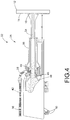
- Control over the degree of melting of the particles of the coating precursor 38 during the block 44 may be achieved by adjusting the temperature of the gas stream 46 by tuning various thermal spray deposition parameters, such as the fuel-to-oxygen ratio, the total volume of fuel and oxygen, and/or the feed rates of fuel and oxygen fed into the combustion chamber 48 from oxygen/fuel supply lines 50 (see FIG. 4 ).
- hydrophobic coatings may be produced using fuel-to-oxygen ratios of between about 0.5 to about 0.9, fuel feed rates of between about 4.68 to about 8,33 litres per hour (about 1.5 to about 2.2 gallons per hour (GPH)), and oxygen feed rates of between about 16.99 to about 25.49 cubic meters per hour (about 600 to about 900 standard cubic feet per hour (SCFH)).
- GPH gallons per hour
- SCFH standard cubic feet per hour
- the selection of the thermal spray parameters may take the thermal mass(es) (i.e., the energy required to melt) of the particles forming the coating precursor 38 into account, and the thermal mass(es) of the particles may be a function of the size, surface area, and porosity of the particles making up the coating precursor 38.
- the relative degree of melting of the different particles may also be tuned, at least to a degree, by varying the above parameters. It is also noted that if the coating precursor 38 contains polymeric particles, lower fuel-to-oxygen ratios (e.g., ⁇ 1) may be used to prevent complete melting and/or burning of the polymeric particles.
- the at least partially melted coating precursor particles may then be accelerated towards the surface 14 of the substrate 12 according to a next block 52. More specifically, the coating precursor particles may be accelerated toward the substrate 12 in a spray jet 54 flowing out of a nozzle 56 of the thermal spray torch 34, as shown in FIG. 4 . According to a next block 58, the coating precursor particles may then be allowed to impact the substrate 12 in a partially melted state in which a fraction of the initial particle morphology of at least some of the particles of the coating precursor 38 is retained.
- the retained initial particle morphology may be correlated with the roughness (e.g., average roughness (R a ), etc.) of the resulting hydrophobic coating 16, with smaller roughnesses compared to the initial particle size correlating with lower fractions of retained particle morphologies.
- the hydrophobic coating 16 may be provided according to a next block 60.
- a stand-off distance ( d ) between the thermal spray torch 34 and the substrate 12 may be varied during the blocks 52, 58, and 60 to regulate the amount of heating of the hydrophobic coating 16 and the substrate 12, with smaller stand-off distances (d) tending to cause increased heating of the hydrophobic coating/substrate as well as increased oxide contents in the hydrophobic coating 16. Greater stand-off distances (d) may allow the particles exiting the thermal spray torch 34 to at least partially unmelt and reach a more hardened state, thereby producing a more rough/hydrophobic surface upon impact with the substrate 12.
- a raster speed at which the thermal spray torch 34 is passed over the substrate 12 may also be varied during the blocks 52, 58, and 60 to regulate the degree of heating of the hydrophobic coating/substrate, with faster raster speeds reducing the degree of heating of the hydrophobic coating/substrate.
- raster speeds in the range of about 900 millimeters per second to about 1100 millimeters per second to produce hydrophobic coatings.
- raster speeds outside of this range may certainly be used in some circumstances depending on various factors such as, but not limited to, particle type, substrate type, other thermal spray settings, and/or the type of thermal spray equipment used.
- FIG. 5 provides a schematic representation of different particle compositions for which may be used as the coating precursor 38.
- coating precursor (A) it may consist of particles of a single component 62 having a single chemical identity and a single particle size and particle morphology.
- the component 62 may not fully melt during the thermal spray deposition process to ensure that at least some of the particles retain at least a fraction of their initial particle morphology upon impact with the substrate 12 to produce surface roughness.
- at least some of the particles of the component 62 may at least partially melt to ensure that the particles suitably adhere to the substrate 12.
- the coating precursor 38 may consist of a single component 63 having a single chemical identity, but with different particle sizes and particle morphologies. More specifically, the single component 63 may consist of a primary component 64 present at more than 50 weight percent and having a larger thermal mass (e.g., larger radius, less porous, and/or lower surface area, etc.) than a secondary component 65, such that the primary component 64 may require more energy/heat to melt. During the thermal spray deposition process, the primary component 64 may remain fully unmelted to promote surface roughness, provided that at least some of the particles of the secondary component 65 are at least partially melted to promote surface adhesion.
- a primary component 64 present at more than 50 weight percent and having a larger thermal mass (e.g., larger radius, less porous, and/or lower surface area, etc.) than a secondary component 65, such that the primary component 64 may require more energy/heat to melt.
- the primary component 64 may remain fully unmelted to promote surface roughness, provided that at least some of the particles of the secondary component
- the primary component 64 and the secondary component 65 may both be heated to partially melted states in which both the primary component 64 and the secondary component 65 may contribute to surface roughness, perhaps even multi-length scale surface roughness.
- multi-length scale surface roughness in hydrophobic coatings produced using coating precursor composition (B) may result from the different particle sizes of the primary component 64 and the secondary component 65 and/or the relative degrees of melting of the primary component 64 and the secondary component 65.
- coating precursor composition (B) may further include additional components with the same chemical identity but having different particle sizes and/or particle morphologies.
- the coating precursor 38 may consist of a mixture of two or more components having different chemical identities but the same particle size and particle morphology.
- the coating precursor composition (C) may include a primary component 66 present at more than 50 weight percent and a secondary component 67 present at less than 50 weight percent, although additional components may also be included.
- the primary component 66 may impart mechanical properties to the resulting hydrophobic coating 16 (e.g., hardness, fracture toughness, elastic modulus, surface adhesion, durability, wear resistance, etc.), while the secondary component 67 may impart hydrophobic and superhydrophobic/icephobic properties to the hydrophobic coating 16 (e.g., lower surface energy, roughness, etc.).
- the primary component 66 may be at least partially melted to promote surface adhesion, while the secondary component 67 may be at least partially unmelted so that it retains at least a fraction of its initial morphology and creates a rough/hydrophobic surface.
- both the primary component 66 and the secondary component 67 may contribute varying degrees of mechanical properties and hydrophobic properties to the hydrophobic coating 16.
- any multi-length scale surface roughness in hydrophobic coatings produced using coating precursor composition (C) may result from the relative degrees of melting of the primary component 66 and the secondary component 67.
- the particles of coating precursor composition (D) may include a mixture of two or more components having different chemical identities and different particle sizes and particle morphologies.
- coating precursor composition (D) may include a primary component 68 present at more than 50 weight percent and having a different chemical identity and particle size/morphology than a secondary component 69, although more than two components may also be used.
- the primary component 68 and the secondary component 69 may impart either mechanical properties (e.g., hardness, fracture toughness, elastic modulus, surface adhesion, durability, wear resistance, etc.) or hydrophobic properties (e.g., roughness, lower surface energy, etc.) to the hydrophobic coating 16.
- the primary component 68 may be at least partially melted by the thermal spray deposition process to ensure that it sufficiently adheres to the substrate 12 and contributes to the durability of the resulting hydrophobic coating 16, while the secondary component 69 may be at least partially unmelted so that it retains at least a fraction of its initial particle morphology and contributes to the roughness of the resulting hydrophobic coating 16.
- the primary component 68 may be at least partially unmelted during the thermal spray deposition process so that it retains at least a fraction of its initial particle morphology, while the secondary component 69 may be at least partially melted so that it sufficiently adheres to the substrate 12.
- the primary component 68 and the secondary component 69 may each contribute varying degrees of mechanical properties and hydrophobic properties as well.
- any multi-length scale surface roughness in hydrophobic coatings produced with coating precursor composition (D) may result from the different particle sizes of the primary component 68 and the secondary component 69 and/or varying degrees of melting of the primary component 68 and the secondary component 69.
- FIG. 6 shows a schematic representation of a hydrophobic coating 16 prepared using coating precursor composition (C), wherein the primary component 66 and the secondary component 67 have different chemical identities but the same particle size and particle morphology.
- the primary component 66 may be particles of poly ether ether ketone (PEEK) which may contribute mechanical properties to the hydrophobic coating 16
- the secondary component 67 may be particles of polytetrafluroethylene (PTFE) which has a lower surface energy and may contribute hydrophobic properties to the hydrophobic coating 16.
- FIG. 7 is a schematic representation of a hydrophobic coating 16 prepared using coating precursor composition (D), wherein the primary component 68 and the secondary component 69 have different chemical identities and different particle sizes/morphologies.
- the primary component 68 may formed from PEEK particles and the secondary component 69 may be formed from PTFE particles, although several other combinations are also possible.
- the block 30 may be carried out by first feeding the thermal spray torch 34 with secondary particles 72 according to a block 74, as described above (i.e., block 36).
- the secondary particles 72 may have a lower surface energy and/or a particle size that is at least one order of magnitude smaller than the coating precursor particles 38 used to produce the hydrophobic coating 16.
- the secondary particles 72 may then be heated with the thermal spray torch 34 to at least a partially melted state, accelerated towards the substrate 12, and allowed to impact the substrate 12 in a partially melted state in which a fraction of the initial particle morphology of at least some of the secondary particles 72 is retained to provide the additional layer 70 on the hydrophobic coating 16 (blocks 76, 78, 80, and 82).
- the degree of melting of the secondary particles 72 during the blocks 76, 78, and 80 may be tuned by varying the thermal spray deposition parameters such as the fuel-to-oxygen ratio, the total fuel and oxygen volume, the fuel and oxygen feed rates, the stand-off distance ( d ), and/or the raster speed of the thermal spray torch 34.
- the thermal spray deposition parameters may be tuned to ensure that the secondary particles 72 are melted enough to promote adhesion to the hydrophobic coating 16, but not fully melted such that the at least some of the secondary particles 72 retain a fraction of their initial particle morphology to enhance surface roughness.
- the resulting hydrophobic coating 16 may have an enhanced hydrophobicity (as shown by a higher water contact angle ( ⁇ ) with a water droplet 17) as a consequence of the lower surface energy provided by the secondary particles 72 and/or the enhanced surface roughness provided by the smaller secondary particles 72.
- the additional layer 70 may introduce multi-length scale surface roughness into the hydrophobic coating 16.
- subsequent additional layers 70 may be deposited on the hydrophobic coating 16 by repeating the method of FIGs. 8-9 , wherein each subsequent additional layer 70 has a particle size that is smaller than the particle size of the previous layer.
- the additional layer(s) 70 may each be a very thin layer, such as a monolayer (e.g., with single particle thickness), that is substantially thinner than the hydrophobic coating 16.
- each additional layer 70 may be a monolayer of the secondary particles 72 covering between about 70% to about 150% of the surface of the hydrophobic coating 16, although the surface coverage of the secondary particles 72 may extend beyond this range in some circumstances. Accordingly, the additional layer(s) 70 may be at least partially transparent such that the hydrophobic coating 16 may be visible through the additional layer(s) 70.
- thermoplastic polymer powders such as polyether ether ketone (PEEK).
- PEEK polyether ether ketone
- HVOF thermal spray equipment was used to deposit PEEK powders having a 50 micrometer particle diameter according to the method of FIGs. 3-4 . Since typical HVOF thermal spray processes heat particles to temperatures in excess of 1000°, the HVOF thermal spray torch was set to a low fuel-to-oxygen ratio ( ⁇ 0.65) and higher stand-off distances ( d ) to reduce total heat input into the PEEK particles and prevent complete melting and/or burning of the polymer particles.
- Table I shows the mean roughness depth (R z ), the average roughness (R a ), and the relative oxide content of PEEK coatings produced by HVOF thermal spraying at various stand-off distances (d).
- the roughness of the PEEK coatings increases with increasing stand-off distances ( d ) due to decreased heating/melting of the PEEK particles at higher stand-off distances ( d ).
- lower stand-off distances ( d ) leads to higher oxide contents (i.e., lower surface energies) due to increased heating of the deposited film which enhances the oxide content.
- the thermal spray parameters may be varied to control the roughness, the oxide content, and the ultimate degree of hydrophobicity of PEEK coatings. Table 1.
- FIG. 10 shows the water contact angle ( ⁇ ) of various polymer-based coatings as a function of stand-off distance ( d ) at a fuel-to-oxygen ratio of ⁇ 0.65.
- the hydrophobicity (i.e., water contact angle ( ⁇ )) of pure PEEK coatings produced from 50 micrometer PEEK particles generally increases with increased stand-off distances (d) due to decreased heating/melting and roughness of the deposited PEEK particles.
- the disclosure herein may be used to produce hydrophobic and superhydrophobic/icephobic coatings from a variety of precursor materials such as, but not limited to, polymer powders, metal or metal alloy powders, polymer powder and metal/metal alloy powder mixtures, and polymer powder and polymeric or metal/metal alloy nanoparticle mixtures by tuning the thermal spray deposition parameters.
- precursor materials such as, but not limited to, polymer powders, metal or metal alloy powders, polymer powder and metal/metal alloy powder mixtures, and polymer powder and polymeric or metal/metal alloy nanoparticle mixtures by tuning the thermal spray deposition parameters.
- composite materials e.g., polymers loaded with nanoparticles, etc.
- thermal spray coatings disclosed herein may also be used to impart other types of properties to substrate surfaces as well such as, but not limited to, anti-fouling properties, conductive properties, and/or biocidal properties.
- coatings formed from metal nanoparticles may impart conductive properties or biocidal properties (e.g., copper nanoparticles), while certain types of polymers (e.g., zwitterionic polymers, etc.) may be used to impart anti-fouling properties.
- the technology disclosed herein has industrial applicability in a variety of settings such as, but not limited to, industrial applications which may benefit from components having hydrophobic and superhydrophobic/icephobic surfaces.
- the technology disclosed herein relies solely on thermal spray deposition methods to produce hydrophobic and superhydrophobic/icephobic coatings from a range of starting precursor powders, including polymeric powders.
- the methods of the present disclosure may be used to apply durable hydrophobic and superhydrophobic/icephobic coatings on a variety of industrial products, even products with large surface areas (e.g., marine equipment, bridges, pipes, aircraft wings, etc.), at high deposition rates and under atmospheric conditions.
- thermal spray technologies are typically used to apply smooth metallic, ceramic, or cermet coatings
- the present disclosure implements thermal spray deposition processes to produce roughened/hydrophobic coatings by controlling the degree of melting of the coating precursors such that at least a fraction of the initial particle morphology is retained upon impact with the substrate.
- the degree of melting and the roughness of the resulting coating may be tuned by varying the thermal spray deposition parameters such as the fuel-to-oxygen ratio, the stand-off distance ( d ), the fuel and oxygen feed rates, and the raster speed. It is expected that the technology disclosed herein may find wide industrial applicability in a wide range of areas such as, but not limited to, aerospace, marine, power, transportation, construction, and defense industries.
Description
- The present disclosure generally relates to hydrophobic and superhydrophobic/icephobic coatings, and more specifically, relates to methods for producing hydrophobic and superhydrophobic/icephobic coatings on substrate surfaces using thermal spray techniques.
- The development of durable hydrophobic and superhydrophobic/icephobic coatings is of great interest to numerous industries, such as aerospace, marine, power, transportation, construction, and defense industries. The ability of hydrophobic and superhydrophobic/icephobic coatings to repel water and ice may impart coated components with advantageous properties such as resistance to wetting, corrosion, swelling, rotting, cracking, and fouling. For example, hydrophobic coatings applied to ship hulls may reduce friction in water and improve efficiency, while superhydrophobic/icephobic coatings on high voltage and telephone wires may assist in preventing ice build-up on power and communication lines during winter storms.
- The hydrophobicity and superhydrophobicity/icephobicity of a coating is characterized by the water contact angle (θ) of the coating, which is the angle at which a water droplet contacts the surface of the coating. Coatings that have a water contact angle (θ) of below 90° are characterized as hydrophilic, while coatings that have a water contact angle (θ) of greater than 90° are characterized as hydrophobic (or water-repelling). If the water contact angle (θ) of a coating is 150° or more, the coating is still hydrophobic but is characterized as "superhydrophobic" and will likely have icephobic (or ice-repelling) properties as well.
- Several methods for generating hydrophobic and superhydrophobic/icephobic coatings have been reported in the literature. For example, superhydrophobic and anti-icing coatings have been produced using a thermal spray process to deposit a base coating which is used as a binder for silicon-based particles that impose the coating with superhydrophobic properties. However, many existing hydrophobic and superhydrophobic/icephobic coatings suffer from drawbacks such as poor substrate adhesion and poor coating durability. Moreover, some methods for applying hydrophobic and superhydrophobic/icephobic coatings may be limited to lab-scale quantities as the methods may rely on vacuum conditions or specialized techniques such as magnetron sputtering or electrodeposition.
- The publication "Effect of surface roughness parameters on thermally sprayed PEEK coatings", Surface and coatings technology, vol. 204, no 21-22, pages 3567-3572, states, according to its abstract, single splats and coatings of PEEK (polyether ether ketone) were produced using high velocity oxygen fuel (HVOF) and assisted combustion high velocity air fuel (AC-HVAF) thermal spray techniques respectively to investigate the effect of varying surface roughness and chemistry of the ANSI304 stainless steel Substrates had on the formation of PEEK coatings. As received degreased, etched and steel grit blasted surface treatments were used. XPS analysis showed that the etched Substrate had the most chemically clean surface confirmed by contact angle measurement which showed that the etched Substrate had the lowest contact angle indicating good Wetting properties followed by the degreased and the steel grit blasted Substrates. Roughness and skewness measurements of the treatment Substrates showed the steel grit blasted surface to have the highest roughness value followed by the etched and degreased Substrates whose roughness values were an order of magnitude lower. Skewness was positive on the etched Substrate, slightly negative on the steel grit and negative on the degreased Substrate. PEEK Single splat image analysis showed that splats per mm2 were highest on the steel grit blasted Substrate followed by degreased and etched respectively. Scratch testing of the PEEK coatings showed coating failure on the steel grit Substrate to be cohesive, on the degreased Substrate, adhesive and on the etched Substrate a combination of both. From these results it was concluded that a positive skewness ANSI304 stainless steel surface can be produced using an etching process, and for surfaces with suitable topography mechanical interlocking may play a more significant role than surface chemistry for room temperature Substrates. HVOF and AC-HVAF thermal spraying of PEEK coatings onto stainless steel surfaces and for ANSI304 stainless steel surfaces with comparable roughness and PEEK coatings on surfaces with positive skewness show better coating adhesion than similar surfaces with negative skewness.
- The publication "Wear resistance of PEEK and PTFE composite coatings", 2nd polymer conference of Thailand, vol. PI-OP-10, pages 92-95, states, according to its abstract, polyetheretherketone/polytetrafluoroethylene (PEEK/PTFE) composite coatings were prepared on low carbon steel via flame spraying. The friction and wear rate of the composite coatings were performed using a ball-on-disc lest rig in environments of air. The morphologies and wom surfaces of the PEEK/PTFE coatings were also observed using the optical microscope and the scanning electron microscope. The specific wear rate, friction coefficient and hardness of the different compositions were improved with an increase of PEEK content.
- In
EP 0 988 898 A2 - The publication "Icephobic PTFE coatings for wind turbines operating in cold climate conditions", Electrical power & energy conference, pages 1-6, states, according to its abstract, a new treatment offers a simple and inexpensive method to reduce considerably ice adhesion on a wind turbine blade surface ensuring a safe and reliable energy production during winter periods. This treatment has icephobic characteristics, satisfactory mechanical, optical and electrical properties and doesn't alter the surface appearance. The technique consists in depositing a poly(tetrafluoroethylene) or PTFE coating, which strongly clings on a high porosity blade surface. A uniform coating was obtained by dipping the blade samples in a PTFE Solution dispersion followed by annealing at 290°C for 2 min in an argon atmosphere. The resulting film yielded a contact angle around 145°, a hysteresis of 30°, a surface tension estimated to 11.7 mN/m and a slipping angle of 45° even at temperature as low as -6°C. The shear strength of ice adhesion was reduced by 80% compared to pristine blade surface at temperatures ranging from -1.8°C to -12.5°C. There was no observed effect of ice shedding events and no accelerated aging was observed through UVC IrradiatiRon and corrosive acidic Solution on the hydrophobicity of the coated surface. The low surface energy of that coating is promising for its use in the wind turbine industry.
WO 2006/115558 A2 states, according to its abstract, a plasma spray process for structuring self-cleaning glass surfaces and self-cleaning glass surfaces formed according to the process. Molten or heat softened particles of inorganic material are plasma spray deposited onto the surface of a substrate to create a micro-rough surface. If desired, a hydrophobic top coating layer can optionally be applied to the micro-rough surface. The micro-structured surface formed according to the invention is durable and self-cleaning. -
US 2008/311382 A1 states, according to its abstract, an article with a coating on its surface is described herein. The coating has at least one underlayer and a top layer. The underlayer includes one or more high-performance thermoplastics and inorganic fillers and the top layer includes one or more high-performance thermoplastics. - Thus, there are challenges and limitations of existing art that are to be overcome. While the above described systems for producing hydrophobic and superhydrophobic/icephobic coatings are effective, it is desirable to improve these techniques for applications on larger parts with large surface areas and/or parts with diverse shapes under atmospheric conditions. In addition, it is desirable to improve the substrate adhesion and durability of hydrophobic and superhydrophobic/icephobic coatings.
- Disclosed herein are methods for producing durable hydrophobic and superhydrophobic/icephobic coatings on a variety of substrates, including large substrates, under atmospheric conditions. In accordance with one aspect of the present disclosure, a method for forming a hydrophobic coating on a substrate by a thermal spray deposition process is disclosed. The method comprises feeding a thermal spray apparatus with a coating precursor which includes coating precursor particles having an initial particle morphology. The method further comprises heating the coating precursor particles with the thermal spray apparatus to cause the coating precursor particles to at least partially melt, and accelerating the coating precursor particles towards the substrate using the thermal spray apparatus. In addition, the method further comprises forming the hydrophobic coating on the substrate by allowing the coating precursor particles to impact the substrate in a partially melted state in which a fraction of the initial particle morphology of at least some of the coating precursor particles is retained. The method further comprises applying an additional layer on the hydrophobic coating by a thermal spray deposition process comprising: feeding the thermal spray apparatus with secondary particles having an initial secondary particle morphology, the secondary particles having at least one of a lower surface energy and a smaller particle size than the coating precursor particles, heating the secondary particles with the thermal spray apparatus to cause the secondary particles to at least partially melt, accelerating the secondary particles towards the substrate using the thermal spray apparatus, and forming the additional layer on the hydrophobic coating by allowing the secondary particles to impact the hydrophobic coating in a partially melted state in which a fraction of the initial secondary particle morphology of at least some of the secondary particles is retained. The thermal spray apparatus is a HVOF spray torch.
- The features, functions, and advantages that have been discussed can be achieved independently in various embodiments or may be combined in yet other embodiments further details of which can be seen with reference to the following description and drawings.
-
-
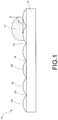
FIG. 1 is a schematic representation of a hydrophobic coating deposited on a substrate and having a water contact angle (θ) with a water droplet, constructed in accordance with the present disclosure. -
FIG. 2 is a flowchart illustrating a sequence of steps which may be involved in producing the hydrophobic coating on the substrate, in accordance with a method the present disclosure. -
FIG. 3 is a flowchart illustrating a sequence of steps which may be involved in depositing the hydrophobic coating on the substrate by a thermal spray deposition process, in accordance with a method of the present disclosure. -
FIG. 4 is partial, cross-sectional view of a thermal spray apparatus which may be used to carry out the thermal spray deposition process ofFIG. 3 , in accordance with a method of the present disclosure. -
FIG. 5 is a schematic representation of different coating precursor compositions which may be used to produce the hydrophobic coating ofFIG. 1 , constructed in accordance with the present disclosure. -
FIG. 6 is a schematic representation of a hydrophobic coating formed from coating precursor composition (C) ofFIG. 5 , constructed in accordance with the present disclosure. -
FIG. 7 is a schematic representation of a hydrophobic coating formed from coating precursor composition (D) ofFIG. 5 , constructed in accordance with the present disclosure. -
FIG. 8 is a flowchart illustrating a sequence of steps which may be involved in applying an additional layer over the hydrophobic coating using a thermal spray deposition process, in accordance with a method of the present disclosure. -
FIG. 9 is a schematic illustration of some of the steps ofFIG. 8 , in accordance with a method of the present disclosure. -
FIG. 10 is a data plot of water contact angle (θ) versus stand-off distance (d) between the substrate and the thermal spray apparatus for various polymeric hydrophobic coatings prepared according to the methods of the present disclosure. -
FIG. 11 is a data plot showing the water contact angles (θ) of various hydrophilic, hydrophobic, and near-superhydrophobic/icephobic coatings prepared under varying thermal spray conditions according to the methods of the present disclosure. - It should be understood that the drawings are not necessarily drawn to scale and that the disclosed embodiments are sometimes illustrated schematically. It is to be further appreciated that the following detailed description is merely exemplary in nature and is not intended to limit the invention or the application and uses thereof. Hence, although the present disclosure is, for convenience of explanation, depicted and described as certain illustrative embodiments, it will be appreciated that it can be implemented in various other types of embodiments and in various other systems and environments.
- Referring now to the drawings, and with specific reference to
FIG. 1 , anarticle 10 including asubstrate 12 having asurface 14 to which ahydrophobic coating 16 is applied is shown. Thehydrophobic coating 16 may exhibit a water contact angle (θ) with awater droplet 17 of 90° or more. In some circumstances, the water contact angle (θ) of thehydrophobic coating 16 may exceed 150°, in which case thehydrophobic coating 16 may may be superhydrophobic/icephobic as well. Therefore, although termed "hydrophobic", it will be understood that thehydrophobic coating 16 may also exhibit superhydrophobic/icephobic properties depending on the magnitude of its water contact angle (θ). - As a non-limiting example, the
article 10 may be a commercial aircraft wing, and thesurface 14 may be a leading edge of the commercial aircraft wing. In this example, thehydrophobic coating 16 may protect the leading edge of the wing from ice buildup, and may reduce or eliminate the need for wiring used to actively heat the leading edge. Alternatively, thearticle 10 may be any other type of part which may benefit from hydrophobic and/or superhydrophobic/icephobic properties such as, but not limited to, a telephone or power wire, a pipe, a bridge, or various types of marine equipment. - The
hydrophobic coating 16 may have a roughened surface which may at least partially contribute to the hydrophobicity of thehydrophobic coating 16. This is because air molecules, which are highly hydrophobic, may become entrapped in the protruding surface structures of a roughened surface and repel water and ice. Specifically, thehydrophobic coating 16 may includepeaks 18 andvalleys 20 along the surface of the coating, thereby creating a roughened surface. In general, the average roughness (Ra) (or the average length between thepeaks 18 and the valleys 20) of thehydrophobic coating 16 may be dependent on the diameter of the smallest particles forming thecoating 16. For example, the average roughness (Ra) of thehydrophobic coating 16 may range from about 1 nanometer to about 500 micrometers, or from about 1 nanometer to about 100 micrometers, but may extend well beyond this range such as into the subnanometer or millimeter range as well. In some circumstances, thehydrophobic coating 16 may exhibit multi-length scale surface roughness in which the distance between thepeaks 18 and thevalleys 20 may vary by at least one order of magnitude (e.g., from nanoscale to microscale). Such multi-length scale surface roughness may be particularly advantageous for enhancing the hydrophobic or superhydrophobic/icephobic effect of thecoating 16. - The
substrate 12 may be formed from a range of materials such as, but not limited to, polymers, composites, metals, metal alloys, ceramics, cermets, and combinations thereof. In addition, thehydrophobic coating 16 may be formed from one or more polymers, carbon, metals, metal alloys, composites, nanoparticles, and combinations thereof. Notably, thehydrophobic coating 16 is applied to thesurface 14 of thesubstrate 12 by high velocity oxy-fuel coating spraying (HVOF). The thermal spray deposition parameters may be adjusted to tune the degree of melting of the particles forming thehydrophobic coating 16 in order to control the degree of surface roughness/hydrophobicity of the resulting coating as well as the strength of adhesion of thehydrophobic coating 16 to the surface 14 (see further details below). Specifically, the higher the degree of melting of the particles, the more the particles will flatten and flow freely to adhere to thesubstrate 12 and provide a durable coating. In contrast, the lower the degree of melting of the particles, the more the particles will retain their initial particle morphology and provide a more roughened/hydrophobic surface. Thus, the thermal spray deposition parameters may be adjusted as necessary to arrive at a suitable or optimal degree of particle melting to balance substrate adhesion and surface roughness (see further details below). Moreover, the thermal spray deposition process may be performed under atmospheric conditions and may be used to apply thehydrophobic coating 16 over a range of substrates at high deposition rates, including substrates having large surface areas (>>1 m2) and/or surfaces with curved and/or irregular shapes. - A general overview of a method which may be used to produce the
article 10 is depicted inFIG. 2 . Beginning with afirst block 22, thesubstrate 12 may be selected from a range of products formed from a range of materials (e.g., polymers, metals, composites, ceramics, cermets, etc.) depending on the application of thearticle 10. However, it is noted that the thermal spraying conditions may limit the selection of the substrate in some circumstances. For example, certain polymeric substrates may melt at the high temperature conditions required to melt or partially melt certain metal-based particles. Once the substrate is selected, thesurface 14 of the substrate may be optionally treated to roughen thesurface 14 and promote coating adhesion according to anoptional block 24. Roughening of thesurface 14 may be achieved by mechanical roughening (e.g., grit blasting) or by chemical roughening, such as by surface etching with solvent exposure. - The
hydrophobic coating 16 may then be applied to thesurface 14 of the treated oruntreated substrate 12 by thermal spraying according to anext block 26, as shown. As described in further detail below, the parameters used for the thermal spray deposition may be tuned as needed to control the degree of melting of the particles forming thehydrophobic coating 16, and, therefore, the hydrophobicity and durability of the resultinghydrophobic coating 16. In some cases, thesubstrate 12 may be optionally heated or cooled prior to, during, or after the deposition of thehydrophobic coating 16 to further control the degree of melting of the particles. Once produced, the hydrophobicity of the coating may optionally be enhanced by enhancing an oxide content of the coating (optional block 28) to lower the surface energy of the coating, as lower surface energy coating materials (e.g., oxides, etc.) tend to increase the water contact angle (θ) of a coating. As a non-limiting possibility, the oxide content of thehydrophobic coating 16 may be increased by passing a flame over (e.g., heating) the top layer of the coating without substantially melting the coating, although other methods may also be used. - In addition to the above, the hydrophobicity of the
hydrophobic coating 16 is increased by applying one or more additional layers over thehydrophobic coating 16 according to anoptional block 30. The additional layer(s) are generated from particles having a lower surface energy and/or a smaller size than the particles used to generate thehydrophobic coating 16, thereby lowering the surface energy and/or increasing the degree of multi-length scale roughness of the final coating. In contrast to thehydrophobic coating 16, which may be formed from multiple layers of particles, the additional layer(s) may each be a thin, single particle layer (e.g., a monolayer) (seeFIGs. 8-9 and further details below). - As yet a further possibility, the hydrophobicity of the
hydrophobic coating 16 may be enhanced by performing a combination of theoptional blocks hydrophobic coating 16 is not yet hydrophobic or superhydrophobic/icephobic upon completion of theblock 26, treating thehydrophobic coating 16 according to theblock 28 and/or theblock 30 may boost the hydrophobicity of thecoating 16 to a hydrophobic state (i.e., a water contact angle (θ) of 90° or more) or even a superhydrophobic/icephobic state (i.e., a water content angle (θ) of 150° or more). - Turning now to
FIGs. 3 and4 , a method for carrying out theblock 26 using athermal spray apparatus 32 is shown. Thethermal spray apparatus 32 uses anHVOF spray torch 34. Beginning with ablock 36, acoating precursor 38 may be fed into thethermal spray torch 34, as shown. For example, thecoating precursor 38 may be fed into thethermal spray torch 34 through aninjector 40, with afeed line 42 providing the supply of thecoating precursor 38 to the injector 40 (seeFIG. 4 ). Thecoating precursor 38 may be in the form of a powder consisting of particles having an initial particle size and morphology. In accordance with the present disclosure, the term "morphology" refers to the shape of the particle. The average particle sizes of the powder may range from about 10 nanometers to about 100 micrometers, although particle sizes outside of this range may also be used in some circumstances. Alternatively, thecoating precursor 38 may be in the form of a wire or a rod. - The
coating precursor 38 is then heated to at least a partially melted state with the thermal spray torch according to anext block 44. More specifically, at least some of the particles of thecoating precursor 38 may be at least partially melted to promote the adhesion of the particles to thesurface 14. In addition, at least some of the particles of thecoating precursor 38 may be partially melted or fully unmelted such that the particles retain at least a fraction of their initial morphology to produce a rough surface upon impact with thesubstrate 12. As thethermal spray torch 34 is a HVOF type torch, heating of thecoating precursor 38 may be achieved by injecting the particles into agas stream 46 exiting an outlet of acombustion chamber 48 of thetorch 34, as shown inFIG. 4 . Control over the degree of melting of the particles of thecoating precursor 38 during theblock 44 may be achieved by adjusting the temperature of thegas stream 46 by tuning various thermal spray deposition parameters, such as the fuel-to-oxygen ratio, the total volume of fuel and oxygen, and/or the feed rates of fuel and oxygen fed into thecombustion chamber 48 from oxygen/fuel supply lines 50 (seeFIG. 4 ). Using HVOF thermal spraying, hydrophobic coatings may be produced using fuel-to-oxygen ratios of between about 0.5 to about 0.9, fuel feed rates of between about 4.68 to about 8,33 litres per hour (about 1.5 to about 2.2 gallons per hour (GPH)), and oxygen feed rates of between about 16.99 to about 25.49 cubic meters per hour (about 600 to about 900 standard cubic feet per hour (SCFH)). However, it will be understood that the thermal spray parameters may deviate significantly from these ranges depending on a number of factors in practice such as, but not limited to, particle type, substrate type, and the type of thermal spray equipment used. - The selection of the thermal spray parameters may take the thermal mass(es) (i.e., the energy required to melt) of the particles forming the
coating precursor 38 into account, and the thermal mass(es) of the particles may be a function of the size, surface area, and porosity of the particles making up thecoating precursor 38. In addition, if thecoating precursor 38 is formed from a mixture of particle types, the relative degree of melting of the different particles may also be tuned, at least to a degree, by varying the above parameters. It is also noted that if thecoating precursor 38 contains polymeric particles, lower fuel-to-oxygen ratios (e.g., <1) may be used to prevent complete melting and/or burning of the polymeric particles. - Following the
block 44, the at least partially melted coating precursor particles may then be accelerated towards thesurface 14 of thesubstrate 12 according to anext block 52. More specifically, the coating precursor particles may be accelerated toward thesubstrate 12 in aspray jet 54 flowing out of anozzle 56 of thethermal spray torch 34, as shown inFIG. 4 . According to anext block 58, the coating precursor particles may then be allowed to impact thesubstrate 12 in a partially melted state in which a fraction of the initial particle morphology of at least some of the particles of thecoating precursor 38 is retained. The retained initial particle morphology may be correlated with the roughness (e.g., average roughness (Ra), etc.) of the resultinghydrophobic coating 16, with smaller roughnesses compared to the initial particle size correlating with lower fractions of retained particle morphologies. Following theblock 58, thehydrophobic coating 16 may be provided according to anext block 60. - A stand-off distance (d) between the
thermal spray torch 34 and thesubstrate 12 may be varied during theblocks hydrophobic coating 16 and thesubstrate 12, with smaller stand-off distances (d) tending to cause increased heating of the hydrophobic coating/substrate as well as increased oxide contents in thehydrophobic coating 16. Greater stand-off distances (d) may allow the particles exiting thethermal spray torch 34 to at least partially unmelt and reach a more hardened state, thereby producing a more rough/hydrophobic surface upon impact with thesubstrate 12. In general, applicants have produced hydrophobic coatings with HVOF thermal spraying using stand-off distances (d) in the range of about 7.62 centimeters to about 43.18 centimeters (about 3 inches to about 17 inches). However, stand-off distances (d) outside of this range may certainly be used in some circumstances depending on various factors such as, but not limited to, particle type, substrate type, other thermal spray settings, and the type of thermal spray equipment used. - In addition, a raster speed at which the
thermal spray torch 34 is passed over thesubstrate 12 may also be varied during theblocks -
FIG. 5 provides a schematic representation of different particle compositions for which may be used as thecoating precursor 38. Beginning with coating precursor (A), it may consist of particles of asingle component 62 having a single chemical identity and a single particle size and particle morphology. In this case, thecomponent 62 may not fully melt during the thermal spray deposition process to ensure that at least some of the particles retain at least a fraction of their initial particle morphology upon impact with thesubstrate 12 to produce surface roughness. However, at least some of the particles of thecomponent 62 may at least partially melt to ensure that the particles suitably adhere to thesubstrate 12. - In coating precursor composition (B), the
coating precursor 38 may consist of asingle component 63 having a single chemical identity, but with different particle sizes and particle morphologies. More specifically, thesingle component 63 may consist of aprimary component 64 present at more than 50 weight percent and having a larger thermal mass (e.g., larger radius, less porous, and/or lower surface area, etc.) than asecondary component 65, such that theprimary component 64 may require more energy/heat to melt. During the thermal spray deposition process, theprimary component 64 may remain fully unmelted to promote surface roughness, provided that at least some of the particles of thesecondary component 65 are at least partially melted to promote surface adhesion. Alternatively, theprimary component 64 and thesecondary component 65 may both be heated to partially melted states in which both theprimary component 64 and thesecondary component 65 may contribute to surface roughness, perhaps even multi-length scale surface roughness. In this regard, multi-length scale surface roughness in hydrophobic coatings produced using coating precursor composition (B) may result from the different particle sizes of theprimary component 64 and thesecondary component 65 and/or the relative degrees of melting of theprimary component 64 and thesecondary component 65. It will be understood that coating precursor composition (B) may further include additional components with the same chemical identity but having different particle sizes and/or particle morphologies. - In coating precursor composition (C), the
coating precursor 38 may consist of a mixture of two or more components having different chemical identities but the same particle size and particle morphology. For example, the coating precursor composition (C) may include aprimary component 66 present at more than 50 weight percent and asecondary component 67 present at less than 50 weight percent, although additional components may also be included. Theprimary component 66 may impart mechanical properties to the resulting hydrophobic coating 16 (e.g., hardness, fracture toughness, elastic modulus, surface adhesion, durability, wear resistance, etc.), while thesecondary component 67 may impart hydrophobic and superhydrophobic/icephobic properties to the hydrophobic coating 16 (e.g., lower surface energy, roughness, etc.). Therefore, during the thermal spray deposition process, theprimary component 66 may be at least partially melted to promote surface adhesion, while thesecondary component 67 may be at least partially unmelted so that it retains at least a fraction of its initial morphology and creates a rough/hydrophobic surface. However, in some circumstances, both theprimary component 66 and thesecondary component 67 may contribute varying degrees of mechanical properties and hydrophobic properties to thehydrophobic coating 16. As theprimary component 66 and thesecondary component 67 may have the same particle size and particle morphology, any multi-length scale surface roughness in hydrophobic coatings produced using coating precursor composition (C) may result from the relative degrees of melting of theprimary component 66 and thesecondary component 67. - The particles of coating precursor composition (D) may include a mixture of two or more components having different chemical identities and different particle sizes and particle morphologies. For example, coating precursor composition (D) may include a
primary component 68 present at more than 50 weight percent and having a different chemical identity and particle size/morphology than asecondary component 69, although more than two components may also be used. Theprimary component 68 and thesecondary component 69 may impart either mechanical properties (e.g., hardness, fracture toughness, elastic modulus, surface adhesion, durability, wear resistance, etc.) or hydrophobic properties (e.g., roughness, lower surface energy, etc.) to thehydrophobic coating 16. In the case where theprimary component 68 imparts mechanical properties and thesecondary component 69 imparts hydrophobic properties, theprimary component 68 may be at least partially melted by the thermal spray deposition process to ensure that it sufficiently adheres to thesubstrate 12 and contributes to the durability of the resultinghydrophobic coating 16, while thesecondary component 69 may be at least partially unmelted so that it retains at least a fraction of its initial particle morphology and contributes to the roughness of the resultinghydrophobic coating 16. Alternatively, in the case where theprimary component 68 imparts hydrophobic properties, theprimary component 68 may be at least partially unmelted during the thermal spray deposition process so that it retains at least a fraction of its initial particle morphology, while thesecondary component 69 may be at least partially melted so that it sufficiently adheres to thesubstrate 12. However, it will be understood that theprimary component 68 and thesecondary component 69 may each contribute varying degrees of mechanical properties and hydrophobic properties as well. It will also be understood that any multi-length scale surface roughness in hydrophobic coatings produced with coating precursor composition (D) may result from the different particle sizes of theprimary component 68 and thesecondary component 69 and/or varying degrees of melting of theprimary component 68 and thesecondary component 69. -
FIG. 6 shows a schematic representation of ahydrophobic coating 16 prepared using coating precursor composition (C), wherein theprimary component 66 and thesecondary component 67 have different chemical identities but the same particle size and particle morphology. As a non-limiting possibility, theprimary component 66 may be particles of poly ether ether ketone (PEEK) which may contribute mechanical properties to thehydrophobic coating 16, and thesecondary component 67 may be particles of polytetrafluroethylene (PTFE) which has a lower surface energy and may contribute hydrophobic properties to thehydrophobic coating 16.FIG. 7 is a schematic representation of ahydrophobic coating 16 prepared using coating precursor composition (D), wherein theprimary component 68 and thesecondary component 69 have different chemical identities and different particle sizes/morphologies. As a non-limiting possibility, theprimary component 68 may formed from PEEK particles and thesecondary component 69 may be formed from PTFE particles, although several other combinations are also possible. - Turning now to
FIGs. 8-9 , a method for applying one or moreadditional layers 70 on thehydrophobic coating 16 according to theoptional block 30 is depicted. Theblock 30 may be carried out by first feeding thethermal spray torch 34 withsecondary particles 72 according to ablock 74, as described above (i.e., block 36). Thesecondary particles 72 may have a lower surface energy and/or a particle size that is at least one order of magnitude smaller than thecoating precursor particles 38 used to produce thehydrophobic coating 16. Thesecondary particles 72 may then be heated with thethermal spray torch 34 to at least a partially melted state, accelerated towards thesubstrate 12, and allowed to impact thesubstrate 12 in a partially melted state in which a fraction of the initial particle morphology of at least some of thesecondary particles 72 is retained to provide theadditional layer 70 on the hydrophobic coating 16 (blocks coating precursor 38, the degree of melting of thesecondary particles 72 during theblocks thermal spray torch 34. Namely, the thermal spray deposition parameters may be tuned to ensure that thesecondary particles 72 are melted enough to promote adhesion to thehydrophobic coating 16, but not fully melted such that the at least some of thesecondary particles 72 retain a fraction of their initial particle morphology to enhance surface roughness. - The resulting
hydrophobic coating 16 may have an enhanced hydrophobicity (as shown by a higher water contact angle (θ) with a water droplet 17) as a consequence of the lower surface energy provided by thesecondary particles 72 and/or the enhanced surface roughness provided by the smallersecondary particles 72. For example, if thesecondary particles 72 are at least an order of magnitude smaller than the particles of thecoating precursor 38, theadditional layer 70 may introduce multi-length scale surface roughness into thehydrophobic coating 16. To further enhance the degree of multi-length scale surface roughness and hydrophobicity of thecoating 16, subsequentadditional layers 70 may be deposited on thehydrophobic coating 16 by repeating the method ofFIGs. 8-9 , wherein each subsequentadditional layer 70 has a particle size that is smaller than the particle size of the previous layer. - As the additional layer(s) 70 may only be used to enhance the hydrophobicity of the
hydrophobic coating 16, the additional layer(s) 70 may each be a very thin layer, such as a monolayer (e.g., with single particle thickness), that is substantially thinner than thehydrophobic coating 16. As one possible arrangement, eachadditional layer 70 may be a monolayer of thesecondary particles 72 covering between about 70% to about 150% of the surface of thehydrophobic coating 16, although the surface coverage of thesecondary particles 72 may extend beyond this range in some circumstances. Accordingly, the additional layer(s) 70 may be at least partially transparent such that thehydrophobic coating 16 may be visible through the additional layer(s) 70. - The method of the present disclosure has been used to produce hydrophobic coatings from thermoplastic polymer powders such as polyether ether ketone (PEEK). Specifically, HVOF thermal spray equipment was used to deposit PEEK powders having a 50 micrometer particle diameter according to the method of
FIGs. 3-4 . Since typical HVOF thermal spray processes heat particles to temperatures in excess of 1000°, the HVOF thermal spray torch was set to a low fuel-to-oxygen ratio (∼0.65) and higher stand-off distances (d) to reduce total heat input into the PEEK particles and prevent complete melting and/or burning of the polymer particles. Table I shows the mean roughness depth (Rz), the average roughness (Ra), and the relative oxide content of PEEK coatings produced by HVOF thermal spraying at various stand-off distances (d). As can be seen from the table, the roughness of the PEEK coatings increases with increasing stand-off distances (d) due to decreased heating/melting of the PEEK particles at higher stand-off distances (d). In contrast, lower stand-off distances (d) leads to higher oxide contents (i.e., lower surface energies) due to increased heating of the deposited film which enhances the oxide content. Thus, the thermal spray parameters may be varied to control the roughness, the oxide content, and the ultimate degree of hydrophobicity of PEEK coatings.Table 1. PEEK coating properties as a function of HVOF torch stand-off distances at a 0.65 fuel-to-oxygen ratio. Rz (mean roughness depth) is the vertical distance from the highest peak to the lowest valley. Ra (average roughness) is the average length between the peaks and the valleys. Stand-off (in) Rz (µin) Ra (µin) Oxide Content 14 3920 ± 210 673 ± 29 None 10 3930 ± 190 647 ± 29 Low 6 3680 ± 230 610 ± 36 Moderate 4 1750 ± 190 263 ± 12 Very High - Applicants have also investigated the hydrophobicity (measured by the water contact angle (θ)) of various polymer powder compositions produced at varying HVOF torch stand-off distances (d). In particular,
FIG. 10 shows the water contact angle (θ) of various polymer-based coatings as a function of stand-off distance (d) at a fuel-to-oxygen ratio of ∼0.65. As can be seen from the plot, the hydrophobicity (i.e., water contact angle (θ)) of pure PEEK coatings produced from 50 micrometer PEEK particles generally increases with increased stand-off distances (d) due to decreased heating/melting and roughness of the deposited PEEK particles. Similar trends were observed with 50 micrometer PEEK particles doped with 50 micrometer polytetrafluoroethylene (PTFE) particles, with water contact angles (θ) approaching the superhydrophobic/icephobic region at higher stand-off distances (d). The PEEK and PTFE mixtures fall into the category of coating precursor composition (C) (e.g., different chemical identities with the same particle size), with the PEEK particles providing mechanical properties and the PTFE particles providing hydrophobic properties due to its lower surface energy. Interestingly, doping of the PEEK particles with as low as 1% PTFE (99/1 PEEK/PTFE) was sufficient to observe an enhancement in hydrophobicity over coatings formed from pure PEEK particles. - In addition, as shown in
FIG. 11 , applicants have produced coatings with water contact angles (θ) in the hydrophobic and near superhydrophobic/icephobic region from powders of polymer and metal particles (PEEK + stainless steel (SS)) and metal particles (copper) by thermal spray depositions. In particular, control over the degree of hydrophobicity of the resulting coatings shown inFIG. 11 was achieved by varying different thermal spray parameters such as stand-off distance (d), number of passes over the substrate, fuel and oxygen fuel rates, and fuel-to-oxygen ratio (see Table 2 below which shows the thermal spray parameters for each run number shown inFIG. 11 ).Table 2. HVOF thermal spray parameters for the thermal spray run numbers shown in FIG. 11. run particle particle size (µm) kerosene flow rate (GPH)a O2 flow rate (SCFH)b number of passesc stand-off (in) fuel/oxygen 1 PEEK 50 1.3 733 1+5+1 6 0.83 2 PEEK 50 1.8 600 1+5 6 0.83 3 PEEK 50 1.8 733 1+2 6 0.83 4 PEEK 50 1.8 733 1+5 4 0.68 5 PEEK 1:1 10/50 1.8 733 1+5 10 - 6 PEEK 50 1.3 733 1+5 14 0.68 7 PEEK/SS 1:1 50/10-20 1.8 733 1+1, 1+2, 1+7 10 - 8 PEEK/SS 1:1 50/20-30 1.8 733 1+5+1 10 - 9d Graphite - - - - - - 10e Copper - - - - - - 11 PEEK/PTFE 1:1 50/10 1.8 733 1+5 14 - aGPH = gallons per hour, bSCFH = standard cubic feet per hour; cThe number of passes alternates between number of passes with 'powder off and number of passes with 'powder on', and a comma indicates a pause where the torch is turned off (e.g., 1+5+1 means one pass with 'powder off', five passes with 'powder on', and one pass with 'powder off'); dThermal spray was not involved in generating the graphite coating. A steel surface was coated with a carbon black lubricant from an aerosol can and was baked in an oven to drive off the solvent; eThe copper coating was generated by twin wire arc thermal spray deposition. - Thus, the disclosure herein may be used to produce hydrophobic and superhydrophobic/icephobic coatings from a variety of precursor materials such as, but not limited to, polymer powders, metal or metal alloy powders, polymer powder and metal/metal alloy powder mixtures, and polymer powder and polymeric or metal/metal alloy nanoparticle mixtures by tuning the thermal spray deposition parameters. In this regard, it is noted that composite materials (e.g., polymers loaded with nanoparticles, etc.) may perform as coating precursors as they may be designed to have good adhesion as well as multi-length scale roughness. It is also noted that the thermal spray coatings disclosed herein may also be used to impart other types of properties to substrate surfaces as well such as, but not limited to, anti-fouling properties, conductive properties, and/or biocidal properties. For example, coatings formed from metal nanoparticles may impart conductive properties or biocidal properties (e.g., copper nanoparticles), while certain types of polymers (e.g., zwitterionic polymers, etc.) may be used to impart anti-fouling properties.
- In general, it can therefore be seen that the technology disclosed herein has industrial applicability in a variety of settings such as, but not limited to, industrial applications which may benefit from components having hydrophobic and superhydrophobic/icephobic surfaces. In contrast with other methods for producing hydrophobic and superhydrophobic/icephobic coatings, the technology disclosed herein relies solely on thermal spray deposition methods to produce hydrophobic and superhydrophobic/icephobic coatings from a range of starting precursor powders, including polymeric powders. The methods of the present disclosure may be used to apply durable hydrophobic and superhydrophobic/icephobic coatings on a variety of industrial products, even products with large surface areas (e.g., marine equipment, bridges, pipes, aircraft wings, etc.), at high deposition rates and under atmospheric conditions. Although thermal spray technologies are typically used to apply smooth metallic, ceramic, or cermet coatings, the present disclosure implements thermal spray deposition processes to produce roughened/hydrophobic coatings by controlling the degree of melting of the coating precursors such that at least a fraction of the initial particle morphology is retained upon impact with the substrate. Specifically, the degree of melting and the roughness of the resulting coating may be tuned by varying the thermal spray deposition parameters such as the fuel-to-oxygen ratio, the stand-off distance (d), the fuel and oxygen feed rates, and the raster speed. It is expected that the technology disclosed herein may find wide industrial applicability in a wide range of areas such as, but not limited to, aerospace, marine, power, transportation, construction, and defense industries.
Claims (15)
- A method for forming a hydrophobic coating (16) on a substrate (12) by a thermal spray deposition process, comprising:feeding a thermal spray apparatus (32) with a coating precursor (38), the coating precursor (38) including coating precursor particles having an initial particle morphology (block 36);heating the coating precursor particles with the thermal spray apparatus (32) to cause the coating precursor particles to at least partially melt (block 44);accelerating the coating precursor particles towards the substrate (12) using the thermal spray apparatus (32; block 52); andforming the hydrophobic coating (16) on the substrate (12) by allowing the coating precursor particles to impact the substrate (12) in a partially melted state in which a fraction of the initial particle morphology of at least some of the coating precursor particles is retained (block 58);applying an additional layer (70) on the hydrophobic coating (16) by a thermal spray deposition process comprising:feeding the thermal spray apparatus (32) with secondary particles (72) having an initial secondary particle morphology, the secondary particles (72) having at least one of a lower surface energy and a smaller particle size than the coating precursor particles (block 74);heating the secondary particles (72) with the thermal spray apparatus (32) to cause the secondary particles (72) to at least partially melt (block 76);accelerating the secondary particles (72) towards the substrate (12) using the thermal spray apparatus (32; block 78); andforming the additional layer (70) on the hydrophobic coating (16) by allowing the secondary particles (72) to impact the hydrophobic coating (16) in a partially melted state in which a fraction of the initial secondary particle morphology of at least some of the secondary particles (72) is retained (block 80),wherein the thermal spray apparatus (32) is a HVOF spray torch.
- The method of claim 1, wherein the additional layer (70) is a monolayer that covers between 70% and 150% of a surface of the hydrophobic coating (16).
- The method of claim 1 or 2, wherein the secondary particles (72) have a particle size (65, 69) that is at least one order of magnitude smaller than the coating precursor particles.
- The method of one of claims 1 to 3, wherein the hydrophobic coating (16) includes the additional layer (70), and wherein the hydrophobic coating (16) exhibits multi-length scale surface roughness.
- The method of one of claims 1 to 4, wherein an average roughness of the hydrophobic coating (16) ranges from 1 nanometer to 500 micrometer.
- The method of one of claims 1 to 4, wherein the hydrophobic coating (16) exhibits an average roughness of between 1 nanometer and 100 micrometers.
- The method of one of claims 1 to 6, wherein the coating precursor (38) comprises a powder having an average particle size of between 10 nanometers and 100 mi crometers.
- The method of one of claims 1 to 7, wherein heating the coating precursor particles with the thermal spray apparatus (32) to cause the coating precursor particles to at least partially melt comprises controlling a temperature of a gas stream of the thermal spray apparatus (32) by adjusting an oxygen feed rate and a fuel feed rate of the thermal spray apparatus (32).
- The method of one of claims 1 to 6, wherein forming the hydrophobic coating (16) on the substrate (12) by allowing the coating precursor particles to impact the substrate (12) in a partially melted state comprises adjusting a stand-off distance d between the thermal spray apparatus (32) and the substrate (12).
- The method of any of claims 1 to 9, further comprising heating the hydrophobic coating (16) to enhance an oxide content of the hydrophobic coating (block 28).
- The method of one of claims 1 to 10, wherein the coating precursor (38) consists of a single component (62) having a single chemical identity with a single particle size and single particle morphology.
- The method of one of claims 1 to 10, wherein the coating precursor (38) consists of a primary component (64) and a secondary component (65) having a smaller thermal mass than the primary component (64), wherein the primary component (64)and the secondary component (65) have the same chemical identity but a different particle size and a different particle morphology, and wherein the coating precursor (38) consists of more than 50 weight percent of the primary component (64).
- The method of one of claims 1 to 10, wherein the coating precursor (38) consists of a primary component (66) and a secondary component (67), wherein the primary component (66) and the secondary component (67) have a different chemical identity and a same particle size and a same particle morphology, and wherein the coating precursor (38) consists of more than 50 weight percent of the primary component (66).
- The method of one of claims 1 to 10, wherein the coating precursor consists of a primary component (68) and a secondary component (69), wherein the primary component (68) and the secondary component (69) have a different chemical identity and a different particle size and a different particle morphology, and wherein the coating precursor (38) consists of more than 50 weight percent of the primary component (68).
- The method of one of claims 1 to 14, wherein the substrate (12) is formed from polymers, composites, metals, metal alloys, ceramics, cermets, or combinations thereof.
Applications Claiming Priority (1)
| Application Number | Priority Date | Filing Date | Title |
|---|---|---|---|
| US14/508,846 US11459481B2 (en) | 2014-10-07 | 2014-10-07 | Thermal spray for durable and large-area hydrophobic and superhydrophobic/icephobic coatings |
Publications (2)
| Publication Number | Publication Date |
|---|---|
| EP3006590A1 EP3006590A1 (en) | 2016-04-13 |
| EP3006590B1 true EP3006590B1 (en) | 2021-03-31 |
Family
ID=54359706
Family Applications (1)
| Application Number | Title | Priority Date | Filing Date |
|---|---|---|---|
| EP15185897.4A Active EP3006590B1 (en) | 2014-10-07 | 2015-09-18 | Thermal spray for durable and lage-area hydrophobic and superhydrophobic/icephobic coatings |
Country Status (4)
| Country | Link |
|---|---|
| US (1) | US11459481B2 (en) |
| EP (1) | EP3006590B1 (en) |
| JP (2) | JP7036530B2 (en) |
| CA (1) | CA2897696C (en) |
Families Citing this family (7)
| Publication number | Priority date | Publication date | Assignee | Title |
|---|---|---|---|---|
| US11459481B2 (en) | 2014-10-07 | 2022-10-04 | The Boeing Company | Thermal spray for durable and large-area hydrophobic and superhydrophobic/icephobic coatings |
| DE102017131397A1 (en) * | 2017-12-28 | 2019-07-04 | Raantec Gmbh & Co. Kg | Method and device for sealing a joint gap |
| JP2021066943A (en) * | 2019-10-25 | 2021-04-30 | 株式会社エンプラス | Method for manufacturing composite uneven structure and application thereof |
| EP4058505B1 (en) | 2019-12-11 | 2023-05-24 | Adaptive Surface Technologies, Inc. | Side chain functionalized organosiloxane polymers, coating compositions and ice-phobic coatings thereof |
| CN112030095A (en) * | 2020-08-14 | 2020-12-04 | 北京科技大学 | Method for spraying wear-resistant and corrosion-resistant nickel-chromium coating on surface of workpiece through supersonic flame |
| CN115029655B (en) * | 2022-05-12 | 2023-07-18 | 山东科技大学 | Super-hydrophobic iron-based amorphous gradient coating and preparation method thereof |
| CN115478242B (en) * | 2022-09-16 | 2024-02-20 | 西安交通大学 | High-wear-resistance superhydrophobic coating based on surface high-hardness bump reinforcement and large-area preparation method thereof |
Citations (2)
| Publication number | Priority date | Publication date | Assignee | Title |
|---|---|---|---|---|
| WO2006115558A2 (en) * | 2005-04-27 | 2006-11-02 | Ferro Corporation | Process for structuring self-cleaning glass surfaces |
| US20080311382A1 (en) * | 2005-02-02 | 2008-12-18 | Christoph Stecher | Article with Anti-Adhesion Coating and Method for Production |
Family Cites Families (27)
| Publication number | Priority date | Publication date | Assignee | Title |
|---|---|---|---|---|
| JPH02217458A (en) | 1989-02-20 | 1990-08-30 | Nkk Corp | Method for flame-spraying ceramics-plastics mixture |
| US5250356A (en) * | 1992-08-28 | 1993-10-05 | E. I. Du Pont De Nemours And Company | Cookware coating system |
| JPH0827555A (en) * | 1994-07-12 | 1996-01-30 | Nippon Steel Corp | Slit nozzle for hot-dip metal plating |
| CZ295850B6 (en) | 1994-07-29 | 2005-11-16 | Wilhelm Prof. Dr. Barthlott | Self-cleaning surfaces of objects, process of their preparation and use |
| US5716422A (en) * | 1996-03-25 | 1998-02-10 | Wilson Greatbatch Ltd. | Thermal spray deposited electrode component and method of manufacture |
| EP0988898A3 (en) | 1998-09-23 | 2001-05-02 | Camco International Inc. | Thermal spray application of polymeric material |
| US6136453A (en) * | 1998-11-24 | 2000-10-24 | General Electric Company | Roughened bond coat for a thermal barrier coating system and method for producing |
| US6327452B1 (en) * | 2000-02-14 | 2001-12-04 | Xerox Corporation | Donor rolls and methods of making donor rolls |
| AUPQ859000A0 (en) * | 2000-07-06 | 2000-07-27 | Commonwealth Scientific And Industrial Research Organisation | Apparatus for surface engineering |
| US6838157B2 (en) * | 2002-09-23 | 2005-01-04 | Siemens Westinghouse Power Corporation | Method and apparatus for instrumenting a gas turbine component having a barrier coating |
| JP2004283699A (en) * | 2003-03-20 | 2004-10-14 | Osaka Gas Co Ltd | Member for gas using facility applied with high durable coating |
| AU2003901734A0 (en) * | 2003-04-11 | 2003-05-01 | Unisearch Limited | Transparent superhydrophobic coating |
| JP2006083279A (en) | 2004-09-15 | 2006-03-30 | Seiko Epson Corp | Liquid-repellent particle and manufacturing method of liquid-repellent particle |
| US7579088B2 (en) * | 2004-12-02 | 2009-08-25 | Henkel Kommanditgesellschaft Auf Aktien (Henkel Kgaa) | Increasing and maintaining the hydrophilic nature of an oxidized plastic surface |
| EP1976945A1 (en) | 2006-01-26 | 2008-10-08 | Xiom Corporation | Powder thermal spray compositions composing at least two thermoplastics |
| US7946303B2 (en) * | 2006-09-29 | 2011-05-24 | Lam Research Corporation | Carrier for reducing entrance and/or exit marks left by a substrate-processing meniscus |
| US20100107982A1 (en) * | 2007-03-22 | 2010-05-06 | Kabushiki Kaisha Toshiba | Vacuum deposition apparatus part and vacuum deposition apparatus using the part |
| GB2467780A (en) | 2009-02-16 | 2010-08-18 | Univ Sheffield | Liquid Composite Materials |
| JP4884492B2 (en) * | 2009-03-13 | 2012-02-29 | 株式会社フジコー | Method for forming a photocatalytic functional film |
| DE102010000344A1 (en) * | 2010-02-09 | 2011-08-11 | BAF Industrie- und Oberflächentechnik GmbH, 36452 | Metallic component, method for producing a metallic component and fitting, furniture and / or large household appliance |
| JP6136625B2 (en) * | 2012-06-25 | 2017-05-31 | 新日鐵住金株式会社 | Lubricant for hot working, lubricating coating and hot working method |
| ES2648229T3 (en) | 2012-09-27 | 2017-12-29 | Shield Aerodynamics Llc | Environmental defense shield |
| US9670304B2 (en) | 2012-11-05 | 2017-06-06 | Liang Wang | Composite for preventing ice adhesion |
| US20140178641A1 (en) | 2012-12-21 | 2014-06-26 | General Electric Company | Methods of coating a surface and articles with coated surface |
| KR101519709B1 (en) * | 2013-03-05 | 2015-05-12 | 기아자동차주식회사 | A method and system for die compensation and restoration using high velocity oxy-fuel spray coaitng and plasma ion nitriding |
| US11459481B2 (en) | 2014-10-07 | 2022-10-04 | The Boeing Company | Thermal spray for durable and large-area hydrophobic and superhydrophobic/icephobic coatings |
| CN105316619B (en) * | 2015-10-29 | 2018-01-23 | 中国科学院宁波材料技术与工程研究所 | A kind of method for preparing wear-resisting super-hydrophobic ceramic coating using plasma spray technology and products thereof |
-
2014
- 2014-10-07 US US14/508,846 patent/US11459481B2/en active Active
-
2015
- 2015-07-17 CA CA2897696A patent/CA2897696C/en active Active
- 2015-07-17 JP JP2015142860A patent/JP7036530B2/en active Active
- 2015-09-18 EP EP15185897.4A patent/EP3006590B1/en active Active
-
2021
- 2021-11-22 JP JP2021189429A patent/JP7279143B2/en active Active
Patent Citations (2)
| Publication number | Priority date | Publication date | Assignee | Title |
|---|---|---|---|---|
| US20080311382A1 (en) * | 2005-02-02 | 2008-12-18 | Christoph Stecher | Article with Anti-Adhesion Coating and Method for Production |
| WO2006115558A2 (en) * | 2005-04-27 | 2006-11-02 | Ferro Corporation | Process for structuring self-cleaning glass surfaces |
Also Published As
| Publication number | Publication date |
|---|---|
| JP2022022255A (en) | 2022-02-03 |
| EP3006590A1 (en) | 2016-04-13 |
| CA2897696A1 (en) | 2016-04-07 |
| CA2897696C (en) | 2021-06-08 |
| JP7036530B2 (en) | 2022-03-15 |
| JP7279143B2 (en) | 2023-05-22 |
| US11459481B2 (en) | 2022-10-04 |
| JP2016074970A (en) | 2016-05-12 |
| US20160096972A1 (en) | 2016-04-07 |
Similar Documents
| Publication | Publication Date | Title |
|---|---|---|
| EP3006590B1 (en) | Thermal spray for durable and lage-area hydrophobic and superhydrophobic/icephobic coatings | |
| Ravi et al. | Fabrication of micro-/nano-structured super-hydrophobic fluorinated polymer coatings by cold-spray | |
| Kuroda et al. | Warm spraying—a novel coating process based on high-velocity impact of solid particles | |
| JP6446175B2 (en) | Thermal spray coated reinforced polymer composites | |
| Sahab et al. | Impact of plasma spray variables parameters on mechanical and wear behaviour of plasma sprayed Al2O3 3% wt TiO2 coating in abrasion and erosion application | |
| JP4982859B2 (en) | Formation method of organic film | |
| JP5143820B2 (en) | Hydrophobic glass surface | |
| KR102470075B1 (en) | Cookware comprising a layer of rare earth oxides | |
| EP0988898A2 (en) | Thermal spray application of polymeric material | |
| US20170159156A1 (en) | Iron-based alloy coating and method for manufacturing the same | |
| CN102918181B (en) | Method for cold gas spraying of a layer having a metal microstructure phase and a microstructure phase made of plastic, component having such a layer, and use of said component | |
| WO2007023971A1 (en) | Structural member coated with spray coating film excellent in thermal emission properties and the like, and method for production thereof | |
| Djendel et al. | Characterization of alumina-titania coatings produced by atmospheric plasma spraying on 304 SS steel | |
| CN109735785A (en) | A kind of preparation method of the hydrophobic coating of the wear-resisting satisfactory mechanical property of novel fire resistant | |
| Sarkar et al. | One-step deposition process to obtain nanostructured superhydrophobic thin films by galvanic exchange reactions | |
| Lin et al. | Using response surface methodology with response transformation in optimizing plasma spraying coatings | |
| JP4458911B2 (en) | Plastics composite material and manufacturing method thereof | |
| KR100797827B1 (en) | Method of coating on carbon fiber-epoxy composite | |
| JP5598901B2 (en) | Resin coating member and resin coating method | |
| WO2019208092A1 (en) | Resin molded body | |
| Zhong et al. | Nano-composite coatings with improved mechanical properties and corrosion resistance by thermal spraying | |
| CN114031410B (en) | 1300 ℃ high temperature resistant polymer conversion ceramic coating and preparation method thereof | |
| Cho et al. | Wear behaviors of HVOF spray coating of Co-alloy T800 | |
| Glanc et al. | Microstructure and tribological behavior of HVOF sprayed and laser treated CoCrTaAlCSiY coatings | |
| Rahim et al. | Plasma spray ceramic coating and measurement of developed coating behaviour |
Legal Events
| Date | Code | Title | Description |
|---|---|---|---|
| PUAI | Public reference made under article 153(3) epc to a published international application that has entered the european phase |
Free format text: ORIGINAL CODE: 0009012 |
|
| 17P | Request for examination filed |
Effective date: 20150918 |
|
| AK | Designated contracting states |
Kind code of ref document: A1 Designated state(s): AL AT BE BG CH CY CZ DE DK EE ES FI FR GB GR HR HU IE IS IT LI LT LU LV MC MK MT NL NO PL PT RO RS SE SI SK SM TR |
|
| AX | Request for extension of the european patent |
Extension state: BA ME |
|
| RBV | Designated contracting states (corrected) |
Designated state(s): AL AT BE BG CH CY CZ DE DK EE ES FI FR GB GR HR HU IE IS IT LI LT LU LV MC MK MT NL NO PL PT RO RS SE SI SK SM TR |
|
| STAA | Information on the status of an ep patent application or granted ep patent |
Free format text: STATUS: EXAMINATION IS IN PROGRESS |
|
| 17Q | First examination report despatched |
Effective date: 20180718 |
|
| GRAP | Despatch of communication of intention to grant a patent |
Free format text: ORIGINAL CODE: EPIDOSNIGR1 |
|
| STAA | Information on the status of an ep patent application or granted ep patent |
Free format text: STATUS: GRANT OF PATENT IS INTENDED |
|
| INTG | Intention to grant announced |
Effective date: 20201028 |
|
| GRAS | Grant fee paid |
Free format text: ORIGINAL CODE: EPIDOSNIGR3 |
|
| GRAA | (expected) grant |
Free format text: ORIGINAL CODE: 0009210 |
|
| STAA | Information on the status of an ep patent application or granted ep patent |
Free format text: STATUS: THE PATENT HAS BEEN GRANTED |
|
| AK | Designated contracting states |
Kind code of ref document: B1 Designated state(s): AL AT BE BG CH CY CZ DE DK EE ES FI FR GB GR HR HU IE IS IT LI LT LU LV MC MK MT NL NO PL PT RO RS SE SI SK SM TR |
|
| REG | Reference to a national code |
Ref country code: GB Ref legal event code: FG4D Ref country code: CH Ref legal event code: EP |
|
| REG | Reference to a national code |
Ref country code: DE Ref legal event code: R096 Ref document number: 602015067398 Country of ref document: DE Ref country code: AT Ref legal event code: REF Ref document number: 1377012 Country of ref document: AT Kind code of ref document: T Effective date: 20210415 |
|
| REG | Reference to a national code |
Ref country code: IE Ref legal event code: FG4D |
|
| REG | Reference to a national code |
Ref country code: LT Ref legal event code: MG9D |
|
| PG25 | Lapsed in a contracting state [announced via postgrant information from national office to epo] |
Ref country code: NO Free format text: LAPSE BECAUSE OF FAILURE TO SUBMIT A TRANSLATION OF THE DESCRIPTION OR TO PAY THE FEE WITHIN THE PRESCRIBED TIME-LIMIT Effective date: 20210630 Ref country code: BG Free format text: LAPSE BECAUSE OF FAILURE TO SUBMIT A TRANSLATION OF THE DESCRIPTION OR TO PAY THE FEE WITHIN THE PRESCRIBED TIME-LIMIT Effective date: 20210630 Ref country code: FI Free format text: LAPSE BECAUSE OF FAILURE TO SUBMIT A TRANSLATION OF THE DESCRIPTION OR TO PAY THE FEE WITHIN THE PRESCRIBED TIME-LIMIT Effective date: 20210331 Ref country code: HR Free format text: LAPSE BECAUSE OF FAILURE TO SUBMIT A TRANSLATION OF THE DESCRIPTION OR TO PAY THE FEE WITHIN THE PRESCRIBED TIME-LIMIT Effective date: 20210331 |
|
| PG25 | Lapsed in a contracting state [announced via postgrant information from national office to epo] |
Ref country code: RS Free format text: LAPSE BECAUSE OF FAILURE TO SUBMIT A TRANSLATION OF THE DESCRIPTION OR TO PAY THE FEE WITHIN THE PRESCRIBED TIME-LIMIT Effective date: 20210331 Ref country code: LV Free format text: LAPSE BECAUSE OF FAILURE TO SUBMIT A TRANSLATION OF THE DESCRIPTION OR TO PAY THE FEE WITHIN THE PRESCRIBED TIME-LIMIT Effective date: 20210331 Ref country code: SE Free format text: LAPSE BECAUSE OF FAILURE TO SUBMIT A TRANSLATION OF THE DESCRIPTION OR TO PAY THE FEE WITHIN THE PRESCRIBED TIME-LIMIT Effective date: 20210331 |
|
| REG | Reference to a national code |
Ref country code: NL Ref legal event code: MP Effective date: 20210331 |
|
| REG | Reference to a national code |
Ref country code: AT Ref legal event code: MK05 Ref document number: 1377012 Country of ref document: AT Kind code of ref document: T Effective date: 20210331 |
|
| PG25 | Lapsed in a contracting state [announced via postgrant information from national office to epo] |
Ref country code: LT Free format text: LAPSE BECAUSE OF FAILURE TO SUBMIT A TRANSLATION OF THE DESCRIPTION OR TO PAY THE FEE WITHIN THE PRESCRIBED TIME-LIMIT Effective date: 20210331 Ref country code: NL Free format text: LAPSE BECAUSE OF FAILURE TO SUBMIT A TRANSLATION OF THE DESCRIPTION OR TO PAY THE FEE WITHIN THE PRESCRIBED TIME-LIMIT Effective date: 20210331 Ref country code: CZ Free format text: LAPSE BECAUSE OF FAILURE TO SUBMIT A TRANSLATION OF THE DESCRIPTION OR TO PAY THE FEE WITHIN THE PRESCRIBED TIME-LIMIT Effective date: 20210331 Ref country code: EE Free format text: LAPSE BECAUSE OF FAILURE TO SUBMIT A TRANSLATION OF THE DESCRIPTION OR TO PAY THE FEE WITHIN THE PRESCRIBED TIME-LIMIT Effective date: 20210331 Ref country code: AT Free format text: LAPSE BECAUSE OF FAILURE TO SUBMIT A TRANSLATION OF THE DESCRIPTION OR TO PAY THE FEE WITHIN THE PRESCRIBED TIME-LIMIT Effective date: 20210331 Ref country code: SM Free format text: LAPSE BECAUSE OF FAILURE TO SUBMIT A TRANSLATION OF THE DESCRIPTION OR TO PAY THE FEE WITHIN THE PRESCRIBED TIME-LIMIT Effective date: 20210331 |
|
| PG25 | Lapsed in a contracting state [announced via postgrant information from national office to epo] |
Ref country code: PL Free format text: LAPSE BECAUSE OF FAILURE TO SUBMIT A TRANSLATION OF THE DESCRIPTION OR TO PAY THE FEE WITHIN THE PRESCRIBED TIME-LIMIT Effective date: 20210331 Ref country code: PT Free format text: LAPSE BECAUSE OF FAILURE TO SUBMIT A TRANSLATION OF THE DESCRIPTION OR TO PAY THE FEE WITHIN THE PRESCRIBED TIME-LIMIT Effective date: 20210802 Ref country code: ES Free format text: LAPSE BECAUSE OF FAILURE TO SUBMIT A TRANSLATION OF THE DESCRIPTION OR TO PAY THE FEE WITHIN THE PRESCRIBED TIME-LIMIT Effective date: 20210331 Ref country code: SK Free format text: LAPSE BECAUSE OF FAILURE TO SUBMIT A TRANSLATION OF THE DESCRIPTION OR TO PAY THE FEE WITHIN THE PRESCRIBED TIME-LIMIT Effective date: 20210331 Ref country code: RO Free format text: LAPSE BECAUSE OF FAILURE TO SUBMIT A TRANSLATION OF THE DESCRIPTION OR TO PAY THE FEE WITHIN THE PRESCRIBED TIME-LIMIT Effective date: 20210331 Ref country code: IS Free format text: LAPSE BECAUSE OF FAILURE TO SUBMIT A TRANSLATION OF THE DESCRIPTION OR TO PAY THE FEE WITHIN THE PRESCRIBED TIME-LIMIT Effective date: 20210731 |
|
| REG | Reference to a national code |
Ref country code: DE Ref legal event code: R097 Ref document number: 602015067398 Country of ref document: DE |
|
| PG25 | Lapsed in a contracting state [announced via postgrant information from national office to epo] |
Ref country code: AL Free format text: LAPSE BECAUSE OF FAILURE TO SUBMIT A TRANSLATION OF THE DESCRIPTION OR TO PAY THE FEE WITHIN THE PRESCRIBED TIME-LIMIT Effective date: 20210331 Ref country code: DK Free format text: LAPSE BECAUSE OF FAILURE TO SUBMIT A TRANSLATION OF THE DESCRIPTION OR TO PAY THE FEE WITHIN THE PRESCRIBED TIME-LIMIT Effective date: 20210331 |
|
| PLBE | No opposition filed within time limit |
Free format text: ORIGINAL CODE: 0009261 |
|
| STAA | Information on the status of an ep patent application or granted ep patent |
Free format text: STATUS: NO OPPOSITION FILED WITHIN TIME LIMIT |
|
| 26N | No opposition filed |
Effective date: 20220104 |
|
| REG | Reference to a national code |
Ref country code: CH Ref legal event code: PL |
|
| REG | Reference to a national code |
Ref country code: BE Ref legal event code: MM Effective date: 20210930 |
|
| PG25 | Lapsed in a contracting state [announced via postgrant information from national office to epo] |
Ref country code: IS Free format text: LAPSE BECAUSE OF FAILURE TO SUBMIT A TRANSLATION OF THE DESCRIPTION OR TO PAY THE FEE WITHIN THE PRESCRIBED TIME-LIMIT Effective date: 20210731 Ref country code: MC Free format text: LAPSE BECAUSE OF FAILURE TO SUBMIT A TRANSLATION OF THE DESCRIPTION OR TO PAY THE FEE WITHIN THE PRESCRIBED TIME-LIMIT Effective date: 20210331 |
|
| PG25 | Lapsed in a contracting state [announced via postgrant information from national office to epo] |
Ref country code: LU Free format text: LAPSE BECAUSE OF NON-PAYMENT OF DUE FEES Effective date: 20210918 Ref country code: IT Free format text: LAPSE BECAUSE OF FAILURE TO SUBMIT A TRANSLATION OF THE DESCRIPTION OR TO PAY THE FEE WITHIN THE PRESCRIBED TIME-LIMIT Effective date: 20210331 Ref country code: IE Free format text: LAPSE BECAUSE OF NON-PAYMENT OF DUE FEES Effective date: 20210918 Ref country code: BE Free format text: LAPSE BECAUSE OF NON-PAYMENT OF DUE FEES Effective date: 20210930 |
|
| PG25 | Lapsed in a contracting state [announced via postgrant information from national office to epo] |
Ref country code: LI Free format text: LAPSE BECAUSE OF NON-PAYMENT OF DUE FEES Effective date: 20210930 Ref country code: CH Free format text: LAPSE BECAUSE OF NON-PAYMENT OF DUE FEES Effective date: 20210930 |
|
| PG25 | Lapsed in a contracting state [announced via postgrant information from national office to epo] |
Ref country code: HU Free format text: LAPSE BECAUSE OF FAILURE TO SUBMIT A TRANSLATION OF THE DESCRIPTION OR TO PAY THE FEE WITHIN THE PRESCRIBED TIME-LIMIT; INVALID AB INITIO Effective date: 20150918 |
|
| P01 | Opt-out of the competence of the unified patent court (upc) registered |
Effective date: 20230516 |
|
| PG25 | Lapsed in a contracting state [announced via postgrant information from national office to epo] |
Ref country code: CY Free format text: LAPSE BECAUSE OF FAILURE TO SUBMIT A TRANSLATION OF THE DESCRIPTION OR TO PAY THE FEE WITHIN THE PRESCRIBED TIME-LIMIT Effective date: 20210331 |
|
| PG25 | Lapsed in a contracting state [announced via postgrant information from national office to epo] |
Ref country code: GR Free format text: LAPSE BECAUSE OF FAILURE TO SUBMIT A TRANSLATION OF THE DESCRIPTION OR TO PAY THE FEE WITHIN THE PRESCRIBED TIME-LIMIT Effective date: 20210331 |
|
| PGFP | Annual fee paid to national office [announced via postgrant information from national office to epo] |
Ref country code: GB Payment date: 20230927 Year of fee payment: 9 |
|
| PGFP | Annual fee paid to national office [announced via postgrant information from national office to epo] |
Ref country code: FR Payment date: 20230925 Year of fee payment: 9 Ref country code: DE Payment date: 20230927 Year of fee payment: 9 |