EP4159539B1 - Beleuchtungsmodul für eine fahrzeuglampe eines kraftfahrzeugs - Google Patents
Beleuchtungsmodul für eine fahrzeuglampe eines kraftfahrzeugs Download PDFInfo
- Publication number
- EP4159539B1 EP4159539B1 EP22198908.0A EP22198908A EP4159539B1 EP 4159539 B1 EP4159539 B1 EP 4159539B1 EP 22198908 A EP22198908 A EP 22198908A EP 4159539 B1 EP4159539 B1 EP 4159539B1
- Authority
- EP
- European Patent Office
- Prior art keywords
- lighting module
- wire harness
- sub
- fixation point
- vehicle lamp
- Prior art date
- Legal status (The legal status is an assumption and is not a legal conclusion. Google has not performed a legal analysis and makes no representation as to the accuracy of the status listed.)
- Active
Links
Images
Classifications
-
- B—PERFORMING OPERATIONS; TRANSPORTING
- B60—VEHICLES IN GENERAL
- B60Q—ARRANGEMENT OF SIGNALLING OR LIGHTING DEVICES, THE MOUNTING OR SUPPORTING THEREOF OR CIRCUITS THEREFOR, FOR VEHICLES IN GENERAL
- B60Q1/00—Arrangement of optical signalling or lighting devices, the mounting or supporting thereof or circuits therefor
- B60Q1/02—Arrangement of optical signalling or lighting devices, the mounting or supporting thereof or circuits therefor the devices being primarily intended to illuminate the way ahead or to illuminate other areas of way or environments
- B60Q1/04—Arrangement of optical signalling or lighting devices, the mounting or supporting thereof or circuits therefor the devices being primarily intended to illuminate the way ahead or to illuminate other areas of way or environments the devices being headlights
- B60Q1/06—Arrangement of optical signalling or lighting devices, the mounting or supporting thereof or circuits therefor the devices being primarily intended to illuminate the way ahead or to illuminate other areas of way or environments the devices being headlights adjustable, e.g. remotely-controlled from inside vehicle
- B60Q1/076—Arrangement of optical signalling or lighting devices, the mounting or supporting thereof or circuits therefor the devices being primarily intended to illuminate the way ahead or to illuminate other areas of way or environments the devices being headlights adjustable, e.g. remotely-controlled from inside vehicle by electrical means including means to transmit the movements, e.g. shafts or joints
-
- F—MECHANICAL ENGINEERING; LIGHTING; HEATING; WEAPONS; BLASTING
- F21—LIGHTING
- F21S—NON-PORTABLE LIGHTING DEVICES; SYSTEMS THEREOF; VEHICLE LIGHTING DEVICES SPECIALLY ADAPTED FOR VEHICLE EXTERIORS
- F21S45/00—Arrangements within vehicle lighting devices specially adapted for vehicle exteriors, for purposes other than emission or distribution of light
- F21S45/40—Cooling of lighting devices
- F21S45/47—Passive cooling, e.g. using fins, thermal conductive elements or openings
Definitions
- the present invention relates to a lighting module for a vehicle lamp of an automotive vehicle. More particularly, the present invention relates to an electrical connection assembly of the lighting module of the vehicle lamp.
- Motor vehicle lamps are generally composed of a housing, which is closed by a transparent wall, through which one or more light beams emerge.
- This housing accommodates one or more lighting modules, which are assembled inside the housing by means of a bracket arranged in a chassis, plate or any other similar intermediate device which can bracket the lighting module(s) and which is configured for their assembly inside the housing.
- a bracket can be an individual bracket assigned to one lighting module or a collective bracket holding a plurality of these lighting modules.
- the lighting modules each comprise a light generator comprising at least one light source associated with an optical system.
- optical modules intended to equip motor vehicle headlamps
- some can be movably assembled on the housing.
- DBL-type dynamic bending light
- ADB adaptive driving beam
- a dynamic bending light allows the projected beam to rotate according to the curves present in the path of the vehicle.
- electric actuators comprising a motor and a gear assembly.
- a known lighting module for a vehicle lamp of an automotive vehicle is disclosed in CN 109 855 045 A .
- a flexboard or a flexible printed circuit for example made from polymer into which conductive tracks are integrated.
- the flexboard includes a plurality of connectors. For instance, a first connector is provided to ensure the connection of the flexboard to the lighting module, a second connector connects the flexboard to a main connector of the vehicle lamp, and a third connector connects the flexboard to other control units fixed inside the housing of the vehicle lamp or outside the latter.
- the flexboard is costly, and to provide power supply to various electric loads of the vehicle lamp, it is necessary to have additional wires or cables along with the flexbaord.
- additional wires may be required to provide power supply to the fan of a heat sink of the vehicle lamp.
- the unit of the wiring harness may become rigid, if the wiring harness required to power different electric loads of the vehicle lamp is assembled in only one routing. Further, the rigidity of the wiring harness unit is not favorable as regards the freedom of movement of the lighting module and demands more torque from an actuator of the lighting module for proper operation.
- An object of the invention is to alleviate the above-mentioned problems.
- an object of the invention is to provide a cost effective electrical connection assembly for a lighting module of the vehicle lamp while offering a long-term durability of the electric connection despite possible frequent and repeated movements of the lighting module inside the vehicle lamp.
- Another object of the invention is to provide an electrical connection assembly, which enables to reduce the torque required to rotate the lighting module compared to the torque required to rotate a lighting module equipped with a flexboard.
- Another object of the present invention is to provide an electrical connection assembly that uses a minimum number of wire harness routings and still can provide power supply to different electric loads to the vehicle lamp to perform different lighting and/or signaling functions, without using a flexboard.
- a lighting module for a vehicle lamp of an automotive vehicle comprising an electrical connection assembly having a main connector electrically connected to a power supply of the vehicle lamp by a primary wire harness, and a plurality of secondary connectors configured to provide the power supply to a plurality of electric loads of the vehicle lamp.
- the lighting module further comprises two sub-wire harness portions branching out from the main connector and routed along longitudinal sides of the lighting module to electrically connect the main connector and the plurality of secondary connectors.
- the electrical connection assembly proposed herein is less costly and can provide power supply to all electric loads of the vehicle lamp. Further, the number of wires or cables that can be exchanged between the lighting module and other electric loads of the vehicle lamp can be optimized.
- the torque required to laterally move the lighting module equipped with the electrical connection assembly is reduced.
- load on an actuator of the lighting module can be reduced compared to conventional lighting modules.
- the accuracy of the rotation of the lighting module can be improved with the use of two sub-wire harness portions.
- the lighting module includes a fixed part and a movable part, and the two sub-wire harness portions are connected between the fixed part and the movable part such that points of mechanical connection together produce a freedom of movement limited in space.
- the electrical connection assembly can be arranged in limited space in the lighting module.
- the movable part is connected to the fixed part so as to be able to rotate relatively to the fixed part.
- the rotation movement is relative to an axis of rotation.
- the longitudinal side of the lighting module are parallel to the axis of rotation.
- the fixed part comprises a slot to fix the main connector therein, and a first left fixation point, and a first right fixation point; and the movable part comprises a movable frame provided with a second left fixation point and a second right fixation point.
- the right and left fixation points are situated respectively on the right and on the left.
- the fixation points are intended to fix the wire harness portions to the fixed part and the movable part such that wire harness portions can be firmly held during the movement of the lighting module.
- Left and right directions are relative to the position of the main connector. In a non-limiting embodiment, left and right directions are defined laterally relative to the axis of rotation, in particular perpendicularly to said axis of rotation.
- At least some of the secondary connectors are fixed on the movable part.
- all the secondary connectors are fixed on the movable part.
- the first left fixation point and the second left fixation point are substantially on a same first vertical line; and the first right fixation point and the second right fixation point are substantially on a same second vertical line.
- both the first and second vertical lines are on different lateral positions.
- the two sub-wire harness portions can be vertically positioned in the lighting module, and it results in minimizing the movement of the sub-wire harness portions during the movement of the lighting module. Further, the movement of the sub-wire harness portions can be minimized with the decrease in the length of the sub-wire harnesses between the fixed part and the movable part.
- the vertical direction is to be considered when the lighting module is in its orientation for a normal use when mounted on a vehicle. In a non-limiting embodiment the vertical direction is parallel to the axis of rotation defined above.
- a first sub-wire harness portion of the two sub-wire harness portions is routed from the main connector to one or more secondary connectors of the plurality of the secondary connectors via the first left fixation point and the second left fixation point
- a second sub-wire harness portion of the two sub-wire harness portions is routed from the main connector to remaining secondary connectors via the first right fixation point and the second right fixation point.
- the first sub-wire harness portion and the second first sub-wire harness portion are joined with the first and second left fixation points, and the first and second right fixation points, respectively, by means of ties.
- the fixation points and ties connections with the fixation points ensure to minimize or completely avoid the breakage of the sub-wire harness portions during the movement of the lighting module.
- the fixation points and ties connections with the fixation points ensures that there is no relative movement between the sub connectors/main connector and the wire harness portions.
- the plurality of electric loads include at least a heat sink fan and/or an actuator.
- the plurality of electric loads comports a plurality of light sources, which are configured to perform lighting and/or signaling functions comprising at least one of high beam, low beam, dynamic bending lighting function (DBL) low beam and/or high beam, pixelated beam, Turn indicator (Tl) function, daytime running light (DRL) function, and position lamp.
- lighting and/or signaling functions comprising at least one of high beam, low beam, dynamic bending lighting function (DBL) low beam and/or high beam, pixelated beam, Turn indicator (Tl) function, daytime running light (DRL) function, and position lamp.
- the plurality of light sources is arranged on the movable part.
- the two sub-wire harness portions are routed along parallel longitudinal sidewalls of a heat sink.
- said longitudinal sidewalls are vertical.
- the longitudinal side of the lighting module are parallel to the axis of rotation.
- the present invention also relates to a vehicle lamp comprising at least one lighting module according to the present invention.
- the electrical connection assembly of the at least one lighting module is arranged on a rear side of the vehicle lamp.
- the present invention provides a cost effective electrical connection assembly for a lighting module of the vehicle lamp while offering a long-term durability of the electric connection despite possible frequent and repeated movements of the lighting module inside the vehicle lamp.
- main connector and “secondary connectors” discussed in the specification generally refers to electric connectors configured to join the electrical conductors to create an electrical circuit.
- wire harness or "wiring harness” is commonly used to refer to an assembly comprising a bundle of electrical cables.
- Motor vehicle lamps are generally composed of a housing, which is closed by a transparent outer lens, through which one or more light beams emerge. This housing accommodates one or more lighting modules, which are assembled inside the housing by means of a bracket.
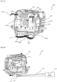
- Fig.1A illustrates a rear perspective view of a lighting module of a vehicle lamp equipped with an electrical connection assembly, according to an embodiment of the present invention.
- Fig.1B illustrates a lighting module of the Fig.1A in which the electrical connection assembly is connected to a power supply of the vehicle lamp, according to an embodiment of the present invention.
- Fig.1C illustrates a side view of the lighting module shown in Fig.1A , according to an embodiment of the present invention.
- the lighting module 100 comprises at least one light source (not shown in the Figures) associated with an optical system (not shown in the Figures).
- the light source is any device able to emit light, such as a filament bulb, a gas-discharge bulb or also a device combining one or more light-emitting semi-conductor light sources, or one or more light-emitting diodes (LEDs).
- the optical system can modify at least one parameter of the light generated by the light source in order to emit the light beam by the lighting module.
- the optical system comprises optical components such as a reflector, lens, diffuser, collimator or any other device (not shown in the Figures) that can modify at least one of the parameters of the light generated by the light source, such as its average reflection and/or its direction, or even a combination of a plurality of these elements (not shown in the Figures).
- optical components such as a reflector, lens, diffuser, collimator or any other device (not shown in the Figures) that can modify at least one of the parameters of the light generated by the light source, such as its average reflection and/or its direction, or even a combination of a plurality of these elements (not shown in the Figures).
- the lighting module 100 is equipped with various devices necessary for its operation, such as means to activate the light source(s), which it comprises, means of cooling and a substructure to carry all the components of the lighting module 100.
- the movable lighting module is used for a dynamic bending light function (DBL), according to which the lighting module is movably assembled on the housing with lateral reflector movement relative to the general axis of forward movement of the vehicle or longitudinal axis of the vehicle.
- DBL dynamic bending light function
- These DBL functions can be applied to low beam functions, then called bending light or dynamic bending light (DBL), or to high beam functions, again called high beam DBL.
- yet another known function lies in the dynamic range levelling of the lighting module 100 based on assembling the lighting module 100 so that it can move on the housing relative to the resting plane of the vehicle on the ground.
- Other complex functions are also known, according to which various lighting modules are movably assembled on the housing and cooperate together in order to obtain selective illumination of the traffic lane, in particular in order to avoid dazzling users of other oncoming vehicles or those being followed.
- the views of the lighting module 100 illustrated in Fig. 1A, Fig. 1B , and Fig.1C shows, for example, the ability of the lighting module 100 to move with lateral rotation movement, to fulfill a headlamp function known as DBL.
- the rotation movement is according to a vertical axis so that the beam projected by the lighting module 100 can move horizontally. It should be noted that the present invention could be applicable to any type of lighting module.
- the lighting module shown in the FIG.1A, Fig.1B and Fig.1C includes a fixed part 105 and a movable part 110.
- the fixed part 105 is a bracket
- the movable part 110 comprises a movable frame 115 (clearly shown in the Fig.2B ), one or more light sources, a light source support, an optical system (not shown in the Figures), and a heat sink 120.
- the one or more light sources, the light source support, the optical system and the heat sink are fixed in the movable frame 115.
- the movable frame 115 is connected to the fixed part 105 so as to be able to rotate relatively to the fixed part 105.
- the connection between the fixed part 105 and the movable frame 115 can be realized for example by bearings.
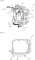
- Fig. 2A illustrates a fixed part of the lighting module shown in the Fig.1A , according to an embodiment of the present invention.
- Fig. 2B illustrates a movable frame of a movable part of the lighting module shown in the Fig.1A , according to an embodiment of the present invention.
- the lighting module 100 comprises an electrical connection assembly 125 arranged between the fixed part 105 and the movable part 110.
- the electrical connection assembly 125 may be arranged on a rear side of the vehicle lamp, i.e., in a direction opposite to the main direction of the light beam emitted by the lighting module 100.
- the electrical connection assembly 125 may be configured to provide power supply to different electric loads of the vehicle lamp.
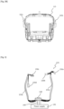
- Fig.3 illustrates a rear view of an electronic connection assembly 125 associated with the lighting module 100, according to the embodiment of the present invention.
- the plurality of electric loads include a plurality of light sources and/or a heat sink fan and/or an actuator (not shown in the Figures).
- the plurality of light sources are configured to perform lighting and/or signaling functions comprising at least one of high beam, low beam, dynamic bending lighting function (DBL) low beam and/or high beam, pixelated beam, Turn indicator (Tl) function, daytime running light (DRL) function, and position lamp.
- DBL dynamic bending lighting function
- Tl Turn indicator
- DDL daytime running light
- the electrical connection assembly 125 of the lighting module 100 comprises a main connector 130 electrically intended to be connected to a power supply 135 (shown in the Fig.1B and Fig.3 ) of the vehicle lamp by a primary wire harness 140.
- the main connector 130 may be arranged in a slot 145 provided on the fixed part 105.
- the main connector is fixed in the slot 145 provided on a bottom portion of the fixed part 105.
- the electrical connection assembly 125 further comprises a plurality of secondary connectors 150a, 150b, 150c, 150d (clearly shown in Fig.3 ) configured to provide the power supply to the plurality of electric loads of the vehicle lamp.
- the secondary connectors 150a, 150b, 150c, 150d may be arranged on the movable part 110.
- the lighting module 100 further comprises two sub-wire harness portions 155a, 155b branching out from the main connector 130 and routed along longitudinal sides of the lighting module 100 to electrically connect the main connector 130 and the plurality of secondary connectors 150a, 150b, 150c, 150d.
- the two sub-wire harness portions 155a, 155b are routed along parallel longitudinal sidewalls of a heat sink 120, as can be seen from the Fig.1A .
- sub-wire harness portions 155a, 155b are illustrated in the exemplary lighting module, it is understood to a person skilled in that art that more than two-wire harness portions can be employed in the electrical connection assembly 125 of the lighting module 100.
- the electrical connection assembly 125 may have three sub-wire harness portions.
- the fixed part 105 is provided with a first left fixation point 160a, and a first right fixation point 160b (clearly shown in Fig.2A ); and the movable frame 115 of the movable part 110 comprises a second left fixation 165a point and a second right fixation point 165b (clearly shown in Fig.2B ).
- the fixation points 160a, 160b, 165a, 165b are intended to fix the wire harness portions 155a, 155b to the fixed part 105 and the movable part 110 such that wire harness portions 155a, 155b can be firmly held during the movement of the movable part 110 of the lighting module 100.
- a first sub-wire harness portion 155a of the two sub-wire harness portions 155a, 155b is routed from the main connector 130 to one or more secondary connectors 150a, 150b of the plurality of the secondary connectors via the first left fixation point 160a and the second left fixation point 165a
- a second sub-wire harness portion 155b of the two sub-wire harness portions 155a, 155b is routed from the main connector 130 to remaining secondary connectors 150c, 150d via the first right fixation point 160b and the second right fixation point 165b.
- first sub-wire harness portion 155a and the second first sub-wire harness portion 155b are joined with the first and second left fixation points 160a, 165a, and the first and second right fixation points 160b, 165b, respectively, by means of ties 170.
- the fixation points 160a, 160b, 165a, 165b and ties 170 connections with the fixation points 160a, 160b, 165a, 165b ensures that the movement of wires is very small and with almost no torsion.
- fixation points 160a, 160b, 165a, 165b and ties 170 connections with the fixation points 160a, 160b, 165a, 165b ensures that there is no relative movement between the sub connectors (150a, 150b, 150c, 150d)/main connector 130 and the wire harness portions 155a, 155b.
- the fixation points 160a, 160b, 165a, 165b and thereby reducing the possibility of breakage during the movement of the lighting module 100.
- a long-term durability of the electric connection is obtained despite possible frequent and repeated movements of the lighting module 100 inside the vehicle lamp.
- the first left fixation point 160a and the second left fixation point 165a are substantially on a same first vertical line; and the first right fixation point 160b and the second right fixation point 165b are substantially on a same second vertical line.
- both the first and second vertical lines are on different lateral positions.
- the sub-wire harness portions 155a, 155b can be vertically positioned in the lighting module 100, and it results in minimizing the movement of the sub-wire harness portions 155a, 155b during the movement of the lighting module 100. Further, the movement of the sub-wire harness portions 155a, 155b can be minimized with the decrease in the length of the sub-wire harnesses portions 155a, 155b between the fixed part 105 and the movable part 110.
- the present invention also relates to a vehicle lamp comprising at least one lighting module 100 as previously described.
- the electrical connection assembly 125 is provided for the vehicle lamps, without using flexboards like in conventional lighting modules.
- the electrical connection assembly 125 proposed herein is less costly and can supply power to all electric loads of the vehicle lamp.
- the number of wires or cables that can be exchanged between the lighting module 100 and other electric loads of the vehicle lamp can be optimized.
- the torque required to laterally move the lighting module 100 equipped with the electrical connection assembly 125 is reduced.
- load on an actuator of the lighting module 100 can be reduced compared to conventional lighting modules.
- the accuracy of the rotation of the lighting module 100 can be improved with the use of sub-wire harness portions 155a, 155b.
- the present invention provides a cost effective electrical connection assembly 125 for the lighting module 100 of the vehicle lamp while offering a long-term durability of the electric connection despite possible frequent and repeated movements of the lighting module 100 inside the vehicle lamp.
Landscapes
- Engineering & Computer Science (AREA)
- Mechanical Engineering (AREA)
- Non-Portable Lighting Devices Or Systems Thereof (AREA)
- Arrangement Of Elements, Cooling, Sealing, Or The Like Of Lighting Devices (AREA)
- Motor Or Generator Frames (AREA)
Claims (9)
- Beleuchtungsmodul (100) für eine Fahrzeuglampe eines Kraftfahrzeugs, wobei das Beleuchtungsmodul (100) Folgendes umfasst: eine elektrische Verbindungsanordnung (125) mit einem Hauptverbinder (130), der dazu geeignet ist, durch einen Primärkabelbaum (140) elektrisch mit einer Stromversorgung (135) der Fahrzeuglampe verbunden zu werden;eine Vielzahl von Sekundärverbindern (150a, 150b, 150c, 150d), die dazu ausgelegt sind, die Stromversorgung (135) einer Vielzahl von elektrischen Lasten der Fahrzeuglampe bereitzustellen; unddadurch gekennzeichnet, dass das Beleuchtungsmodul (100) zwei Teilkabelbaumabschnitte (155a, 155b) umfasst, die sich von dem Hauptverbinder (130) verzweigen und entlang der Längsseiten des Beleuchtungsmoduls (100) geführt sind, um den Hauptverbinder (100) und die Vielzahl von Sekundärverbindern (150a, 150b, 150c, 150d) elektrisch zu verbinden, wobei das Beleuchtungsmodul (100) einen feststehenden Teil (105) und einen beweglichen Teil (110) aufweist, und wobei die zwei Teilkabelbaumabschnitte (155a, 155b) zwischen dem feststehenden Teil (105) und dem beweglichen Teil (110) verbunden sind,wobei der feststehende Teil (105) einen Schlitz (145) zum Befestigen des Hauptverbinders (130) darin und einen ersten linken Befestigungspunkt (160a) und einen ersten rechten Befestigungspunkt (160b) umfasst, wobei die linke und rechte Richtung relativ zur Position des Hauptverbinders sind; undder bewegliche Teil (110) einen beweglichen Rahmen (115) umfasst, der mit einem zweiten linken Befestigungspunkt (165a) und einem zweiten rechten Befestigungspunkt (165b) versehen ist,wobei ein erster Teilkabelbaumabschnitt (155a) der zwei Teilkabelbaumabschnitte (155a, 155b) von dem Hauptverbinder (130) zu einem oder mehreren Sekundärverbindern (150a, 150b) der Vielzahl von Sekundärverbindern über den ersten linken Befestigungspunkt (160a) und den zweiten linken Befestigungspunkt (165a) geführt ist; undein zweiter Teilkabelbaumabschnitt (155b) der zwei Teilkabelbaumabschnitte (155a, 155b) von dem Hauptverbinder (130) zu den verbleibenden Sekundärverbindern (150c, 150d) über den ersten rechten Befestigungspunkt (160b) und den zweiten rechten Befestigungspunkt (165b) geführt ist.
- Beleuchtungsmodul (100) nach Anspruch 1, wobei der erste linke Befestigungspunkt (160a) und der zweite linke Befestigungspunkt (165a) im Wesentlichen auf einer gleichen ersten vertikalen Linie liegen; und
der erste rechte Befestigungspunkt (160b) und der zweite rechte Befestigungspunkt (165b) im Wesentlichen auf einer gleichen zweiten vertikalen Linie liegen, wobei die vertikale Richtung zu berücksichtigen ist, wenn sich das Beleuchtungsmodul in seiner Ausrichtung für eine normale Verwendung befindet, wenn dieses an einem Fahrzeug montiert ist. - Beleuchtungsmodul (100) nach einem der Ansprüche 1 oder 2, wobei der erste Teilkabelbaumabschnitt (155a) und der zweite Teilkabelbaumabschnitt (155b) mit dem ersten und dem zweiten linken Befestigungspunkt (160a, 165a) beziehungsweise dem ersten und zweiten rechten Befestigungspunkt (160b, 165b) mittels Kabelbindern (170) verbunden sind.
- Beleuchtungsmodul (100) nach einem der vorhergehenden Ansprüche, wobei die Vielzahl von elektrischen Lasten mindestens einen Kühlkörperlüfter und/oder einen Aktuator beinhalten.
- Beleuchtungsmodul (100) nach Anspruch 4, wobei die Vielzahl von elektrischen Lasten eine Vielzahl von Lichtquellen umfasst, die dazu ausgelegt sind, Beleuchtungs- und/oder Signalfunktionen auszuführen, die mindestens eines von Fernlicht, Abblendlicht, dynamischem Kurvenlicht (DBL) Abblendlicht und/oder Fernlicht, pixeliertem Lichtstrahl, Blinker(TI)-Funktion, Tagfahrlicht(DRL)-Funktion und Positionslampe umfassen.
- Beleuchtungsmodul (100) nach einem der Ansprüche 4 und 5, wobei die Vielzahl von Lichtquellen auf dem beweglichen Teil (110) angeordnet ist.
- Beleuchtungsmodul (100) nach einem der vorhergehenden Ansprüche, wobei die zwei Teilkabelbaumabschnitte (155a, 155b) entlang paralleler Längsseitenwände eines Kühlkörpers (120) geführt sind.
- Fahrzeuglampe, die mindestens ein Beleuchtungsmodul (100) nach einem der vorhergehenden Ansprüche 1 bis 7 umfasst.
- Fahrzeuglampe nach Anspruch 8, wobei die elektrische Verbindungsanordnung (125) des mindestens einen Beleuchtungsmoduls (100) auf einer Rückseite der Fahrzeuglampe angeordnet ist.
Applications Claiming Priority (1)
| Application Number | Priority Date | Filing Date | Title |
|---|---|---|---|
| FR2110376A FR3127551A1 (fr) | 2021-09-30 | 2021-09-30 | Module d'eclairage pour un phare de vehicule d'un vehicule automobile |
Publications (2)
| Publication Number | Publication Date |
|---|---|
| EP4159539A1 EP4159539A1 (de) | 2023-04-05 |
| EP4159539B1 true EP4159539B1 (de) | 2025-02-19 |
Family
ID=82319941
Family Applications (1)
| Application Number | Title | Priority Date | Filing Date |
|---|---|---|---|
| EP22198908.0A Active EP4159539B1 (de) | 2021-09-30 | 2022-09-30 | Beleuchtungsmodul für eine fahrzeuglampe eines kraftfahrzeugs |
Country Status (2)
| Country | Link |
|---|---|
| EP (1) | EP4159539B1 (de) |
| FR (1) | FR3127551A1 (de) |
Family Cites Families (6)
| Publication number | Priority date | Publication date | Assignee | Title |
|---|---|---|---|---|
| FR2712958B1 (fr) * | 1993-11-23 | 1996-02-16 | Valeo Vision | Projecteur de véhicule notamment automobile. |
| JP4640962B2 (ja) * | 2005-07-29 | 2011-03-02 | 株式会社小糸製作所 | 車両用前照灯 |
| JP4970232B2 (ja) * | 2007-12-12 | 2012-07-04 | 株式会社小糸製作所 | 車両用灯具 |
| DE102014202910A1 (de) * | 2014-02-18 | 2015-08-20 | Automotive Lighting Reutlingen Gmbh | Beleuchtungseinrichtung eines Kraftfahrzeugs |
| FR3037636A1 (fr) * | 2015-06-22 | 2016-12-23 | Valeo Vision | Enveloppe de protection polymerique pour faisceaux electriques dans un dispositif lumineux de vehicule automobile |
| JP2019102230A (ja) * | 2017-11-30 | 2019-06-24 | 株式会社小糸製作所 | 車両用灯具 |
-
2021
- 2021-09-30 FR FR2110376A patent/FR3127551A1/fr active Pending
-
2022
- 2022-09-30 EP EP22198908.0A patent/EP4159539B1/de active Active
Also Published As
| Publication number | Publication date |
|---|---|
| FR3127551A1 (fr) | 2023-03-31 |
| EP4159539A1 (de) | 2023-04-05 |
Similar Documents
| Publication | Publication Date | Title |
|---|---|---|
| CN112543851B (zh) | 具有倾斜的led的柔性led照明条 | |
| US9623792B2 (en) | Vehicle headlight | |
| JP6037619B2 (ja) | 発光モジュールおよび車両用灯具 | |
| EP2722226B1 (de) | Beleuchtungssteuersystem für Fahrzeuglampe | |
| US10393337B2 (en) | Vehicular headlamp | |
| JP5960879B2 (ja) | 遠隔装置に対する電気的接続装置を備える、自動車用ヘッドランプのための光モジュール | |
| JP2020205207A (ja) | 灯具ユニット | |
| CN112113182A (zh) | 灯具单元 | |
| EP4159539B1 (de) | Beleuchtungsmodul für eine fahrzeuglampe eines kraftfahrzeugs | |
| US10859228B2 (en) | Variable headlamp apparatus for vehicle | |
| CN111556945A (zh) | 车辆用前照灯 | |
| CN209926250U (zh) | 用于车辆的前照灯 | |
| JP2019165021A (ja) | 車両用灯具 | |
| US20240343181A1 (en) | Cornering light device for a vehicle projection module and vehicle light system comprising at least one such cornering light device | |
| US9829169B2 (en) | Pivoting mounting of a lighting module for motor vehicles | |
| EP3871960B1 (de) | Scheinwerfer für grätschsitzfahrzeuge | |
| KR102917358B1 (ko) | 차량용 램프 | |
| WO2021025136A1 (ja) | 車両用灯具 | |
| KR102688997B1 (ko) | 자동차용 헤드라이트의 실드장치 | |
| JP2021093326A (ja) | 車両用ランプ | |
| WO2024009935A1 (ja) | 車両用灯具 | |
| KR102778358B1 (ko) | 차량용 램프 | |
| KR20240084756A (ko) | 차량용 램프 | |
| CZ2017734A3 (cs) | Světelné zařízení pro vozidlo | |
| WO2024084015A1 (en) | Aiming system for a vehicle lamp |
Legal Events
| Date | Code | Title | Description |
|---|---|---|---|
| PUAI | Public reference made under article 153(3) epc to a published international application that has entered the european phase |
Free format text: ORIGINAL CODE: 0009012 |
|
| STAA | Information on the status of an ep patent application or granted ep patent |
Free format text: STATUS: THE APPLICATION HAS BEEN PUBLISHED |
|
| AK | Designated contracting states |
Kind code of ref document: A1 Designated state(s): AL AT BE BG CH CY CZ DE DK EE ES FI FR GB GR HR HU IE IS IT LI LT LU LV MC MK MT NL NO PL PT RO RS SE SI SK SM TR |
|
| STAA | Information on the status of an ep patent application or granted ep patent |
Free format text: STATUS: REQUEST FOR EXAMINATION WAS MADE |
|
| 17P | Request for examination filed |
Effective date: 20231004 |
|
| RBV | Designated contracting states (corrected) |
Designated state(s): AL AT BE BG CH CY CZ DE DK EE ES FI FR GB GR HR HU IE IS IT LI LT LU LV MC MK MT NL NO PL PT RO RS SE SI SK SM TR |
|
| GRAP | Despatch of communication of intention to grant a patent |
Free format text: ORIGINAL CODE: EPIDOSNIGR1 |
|
| STAA | Information on the status of an ep patent application or granted ep patent |
Free format text: STATUS: GRANT OF PATENT IS INTENDED |
|
| RIC1 | Information provided on ipc code assigned before grant |
Ipc: F21S 45/42 20180101ALI20240802BHEP Ipc: F21S 45/47 20180101ALI20240802BHEP Ipc: F21S 41/657 20180101ALI20240802BHEP Ipc: F21S 41/19 20180101ALI20240802BHEP Ipc: B60Q 1/076 20060101ALI20240802BHEP Ipc: B60Q 1/00 20060101AFI20240802BHEP |
|
| INTG | Intention to grant announced |
Effective date: 20240910 |
|
| RIN1 | Information on inventor provided before grant (corrected) |
Inventor name: SILES BARRIOS, FRANCISCO JAVIER Inventor name: VALDIVIA MATEOS, GEMA Inventor name: CONTRERAS LUQUE, ANTONIO Inventor name: RAMIREZ MOLINA, JOSE MARIA |
|
| GRAS | Grant fee paid |
Free format text: ORIGINAL CODE: EPIDOSNIGR3 |
|
| GRAA | (expected) grant |
Free format text: ORIGINAL CODE: 0009210 |
|
| STAA | Information on the status of an ep patent application or granted ep patent |
Free format text: STATUS: THE PATENT HAS BEEN GRANTED |
|
| AK | Designated contracting states |
Kind code of ref document: B1 Designated state(s): AL AT BE BG CH CY CZ DE DK EE ES FI FR GB GR HR HU IE IS IT LI LT LU LV MC MK MT NL NO PL PT RO RS SE SI SK SM TR |
|
| REG | Reference to a national code |
Ref country code: GB Ref legal event code: FG4D |
|
| REG | Reference to a national code |
Ref country code: CH Ref legal event code: EP |
|
| REG | Reference to a national code |
Ref country code: IE Ref legal event code: FG4D |
|
| REG | Reference to a national code |
Ref country code: DE Ref legal event code: R096 Ref document number: 602022010754 Country of ref document: DE |
|
| REG | Reference to a national code |
Ref country code: NL Ref legal event code: MP Effective date: 20250219 |
|
| PG25 | Lapsed in a contracting state [announced via postgrant information from national office to epo] |
Ref country code: RS Free format text: LAPSE BECAUSE OF FAILURE TO SUBMIT A TRANSLATION OF THE DESCRIPTION OR TO PAY THE FEE WITHIN THE PRESCRIBED TIME-LIMIT Effective date: 20250519 |
|
| PG25 | Lapsed in a contracting state [announced via postgrant information from national office to epo] |
Ref country code: FI Free format text: LAPSE BECAUSE OF FAILURE TO SUBMIT A TRANSLATION OF THE DESCRIPTION OR TO PAY THE FEE WITHIN THE PRESCRIBED TIME-LIMIT Effective date: 20250219 |
|
| PG25 | Lapsed in a contracting state [announced via postgrant information from national office to epo] |
Ref country code: PL Free format text: LAPSE BECAUSE OF FAILURE TO SUBMIT A TRANSLATION OF THE DESCRIPTION OR TO PAY THE FEE WITHIN THE PRESCRIBED TIME-LIMIT Effective date: 20250219 |
|
| PG25 | Lapsed in a contracting state [announced via postgrant information from national office to epo] |
Ref country code: ES Free format text: LAPSE BECAUSE OF FAILURE TO SUBMIT A TRANSLATION OF THE DESCRIPTION OR TO PAY THE FEE WITHIN THE PRESCRIBED TIME-LIMIT Effective date: 20250219 |
|
| REG | Reference to a national code |
Ref country code: LT Ref legal event code: MG9D |
|
| PG25 | Lapsed in a contracting state [announced via postgrant information from national office to epo] |
Ref country code: NO Free format text: LAPSE BECAUSE OF FAILURE TO SUBMIT A TRANSLATION OF THE DESCRIPTION OR TO PAY THE FEE WITHIN THE PRESCRIBED TIME-LIMIT Effective date: 20250519 Ref country code: IS Free format text: LAPSE BECAUSE OF FAILURE TO SUBMIT A TRANSLATION OF THE DESCRIPTION OR TO PAY THE FEE WITHIN THE PRESCRIBED TIME-LIMIT Effective date: 20250619 |
|
| PG25 | Lapsed in a contracting state [announced via postgrant information from national office to epo] |
Ref country code: NL Free format text: LAPSE BECAUSE OF FAILURE TO SUBMIT A TRANSLATION OF THE DESCRIPTION OR TO PAY THE FEE WITHIN THE PRESCRIBED TIME-LIMIT Effective date: 20250219 |
|
| PG25 | Lapsed in a contracting state [announced via postgrant information from national office to epo] |
Ref country code: HR Free format text: LAPSE BECAUSE OF FAILURE TO SUBMIT A TRANSLATION OF THE DESCRIPTION OR TO PAY THE FEE WITHIN THE PRESCRIBED TIME-LIMIT Effective date: 20250219 |
|
| PG25 | Lapsed in a contracting state [announced via postgrant information from national office to epo] |
Ref country code: LV Free format text: LAPSE BECAUSE OF FAILURE TO SUBMIT A TRANSLATION OF THE DESCRIPTION OR TO PAY THE FEE WITHIN THE PRESCRIBED TIME-LIMIT Effective date: 20250219 Ref country code: PT Free format text: LAPSE BECAUSE OF FAILURE TO SUBMIT A TRANSLATION OF THE DESCRIPTION OR TO PAY THE FEE WITHIN THE PRESCRIBED TIME-LIMIT Effective date: 20250620 |
|
| PG25 | Lapsed in a contracting state [announced via postgrant information from national office to epo] |
Ref country code: BG Free format text: LAPSE BECAUSE OF FAILURE TO SUBMIT A TRANSLATION OF THE DESCRIPTION OR TO PAY THE FEE WITHIN THE PRESCRIBED TIME-LIMIT Effective date: 20250219 Ref country code: GR Free format text: LAPSE BECAUSE OF FAILURE TO SUBMIT A TRANSLATION OF THE DESCRIPTION OR TO PAY THE FEE WITHIN THE PRESCRIBED TIME-LIMIT Effective date: 20250520 |
|
| REG | Reference to a national code |
Ref country code: AT Ref legal event code: MK05 Ref document number: 1768022 Country of ref document: AT Kind code of ref document: T Effective date: 20250219 |
|
| PG25 | Lapsed in a contracting state [announced via postgrant information from national office to epo] |
Ref country code: SE Free format text: LAPSE BECAUSE OF FAILURE TO SUBMIT A TRANSLATION OF THE DESCRIPTION OR TO PAY THE FEE WITHIN THE PRESCRIBED TIME-LIMIT Effective date: 20250219 |
|
| PG25 | Lapsed in a contracting state [announced via postgrant information from national office to epo] |
Ref country code: SM Free format text: LAPSE BECAUSE OF FAILURE TO SUBMIT A TRANSLATION OF THE DESCRIPTION OR TO PAY THE FEE WITHIN THE PRESCRIBED TIME-LIMIT Effective date: 20250219 |
|
| PG25 | Lapsed in a contracting state [announced via postgrant information from national office to epo] |
Ref country code: DK Free format text: LAPSE BECAUSE OF FAILURE TO SUBMIT A TRANSLATION OF THE DESCRIPTION OR TO PAY THE FEE WITHIN THE PRESCRIBED TIME-LIMIT Effective date: 20250219 |
|
| PGFP | Annual fee paid to national office [announced via postgrant information from national office to epo] |
Ref country code: DE Payment date: 20250916 Year of fee payment: 4 |
|
| PG25 | Lapsed in a contracting state [announced via postgrant information from national office to epo] |
Ref country code: IT Free format text: LAPSE BECAUSE OF FAILURE TO SUBMIT A TRANSLATION OF THE DESCRIPTION OR TO PAY THE FEE WITHIN THE PRESCRIBED TIME-LIMIT Effective date: 20250219 |
|
| PG25 | Lapsed in a contracting state [announced via postgrant information from national office to epo] |
Ref country code: AT Free format text: LAPSE BECAUSE OF FAILURE TO SUBMIT A TRANSLATION OF THE DESCRIPTION OR TO PAY THE FEE WITHIN THE PRESCRIBED TIME-LIMIT Effective date: 20250219 |
|
| PGFP | Annual fee paid to national office [announced via postgrant information from national office to epo] |
Ref country code: FR Payment date: 20250929 Year of fee payment: 4 |
|
| PG25 | Lapsed in a contracting state [announced via postgrant information from national office to epo] |
Ref country code: EE Free format text: LAPSE BECAUSE OF FAILURE TO SUBMIT A TRANSLATION OF THE DESCRIPTION OR TO PAY THE FEE WITHIN THE PRESCRIBED TIME-LIMIT Effective date: 20250219 Ref country code: CZ Free format text: LAPSE BECAUSE OF FAILURE TO SUBMIT A TRANSLATION OF THE DESCRIPTION OR TO PAY THE FEE WITHIN THE PRESCRIBED TIME-LIMIT Effective date: 20250219 |
|
| PG25 | Lapsed in a contracting state [announced via postgrant information from national office to epo] |
Ref country code: RO Free format text: LAPSE BECAUSE OF FAILURE TO SUBMIT A TRANSLATION OF THE DESCRIPTION OR TO PAY THE FEE WITHIN THE PRESCRIBED TIME-LIMIT Effective date: 20250219 |
|
| PG25 | Lapsed in a contracting state [announced via postgrant information from national office to epo] |
Ref country code: SK Free format text: LAPSE BECAUSE OF FAILURE TO SUBMIT A TRANSLATION OF THE DESCRIPTION OR TO PAY THE FEE WITHIN THE PRESCRIBED TIME-LIMIT Effective date: 20250219 |
|
| REG | Reference to a national code |
Ref country code: DE Ref legal event code: R097 Ref document number: 602022010754 Country of ref document: DE |
|
| PLBE | No opposition filed within time limit |
Free format text: ORIGINAL CODE: 0009261 |
|
| STAA | Information on the status of an ep patent application or granted ep patent |
Free format text: STATUS: NO OPPOSITION FILED WITHIN TIME LIMIT |
|
| 26N | No opposition filed |
Effective date: 20251120 |