EP4159503B1 - Joint d etancheite chauffant pour une vitre d'un vehicule - Google Patents
Joint d etancheite chauffant pour une vitre d'un vehicule Download PDFInfo
- Publication number
- EP4159503B1 EP4159503B1 EP22197898.4A EP22197898A EP4159503B1 EP 4159503 B1 EP4159503 B1 EP 4159503B1 EP 22197898 A EP22197898 A EP 22197898A EP 4159503 B1 EP4159503 B1 EP 4159503B1
- Authority
- EP
- European Patent Office
- Prior art keywords
- seal
- strips
- film
- heating
- flocking
- Prior art date
- Legal status (The legal status is an assumption and is not a legal conclusion. Google has not performed a legal analysis and makes no representation as to the accuracy of the status listed.)
- Active
Links
Images


Classifications
-
- B—PERFORMING OPERATIONS; TRANSPORTING
- B60—VEHICLES IN GENERAL
- B60J—WINDOWS, WINDSCREENS, NON-FIXED ROOFS, DOORS, OR SIMILAR DEVICES FOR VEHICLES; REMOVABLE EXTERNAL PROTECTIVE COVERINGS SPECIALLY ADAPTED FOR VEHICLES
- B60J10/00—Sealing arrangements
- B60J10/60—Sealing arrangements characterised by defrosting arrangements
-
- B—PERFORMING OPERATIONS; TRANSPORTING
- B60—VEHICLES IN GENERAL
- B60J—WINDOWS, WINDSCREENS, NON-FIXED ROOFS, DOORS, OR SIMILAR DEVICES FOR VEHICLES; REMOVABLE EXTERNAL PROTECTIVE COVERINGS SPECIALLY ADAPTED FOR VEHICLES
- B60J10/00—Sealing arrangements
- B60J10/15—Sealing arrangements characterised by the material
- B60J10/17—Sealing arrangements characterised by the material provided with a low-friction material on the surface
-
- B—PERFORMING OPERATIONS; TRANSPORTING
- B60—VEHICLES IN GENERAL
- B60J—WINDOWS, WINDSCREENS, NON-FIXED ROOFS, DOORS, OR SIMILAR DEVICES FOR VEHICLES; REMOVABLE EXTERNAL PROTECTIVE COVERINGS SPECIALLY ADAPTED FOR VEHICLES
- B60J10/00—Sealing arrangements
- B60J10/70—Sealing arrangements specially adapted for windows or windscreens
- B60J10/74—Sealing arrangements specially adapted for windows or windscreens for sliding window panes, e.g. sash guides
- B60J10/75—Sealing arrangements specially adapted for windows or windscreens for sliding window panes, e.g. sash guides for sealing the lower part of the panes
-
- H—ELECTRICITY
- H05—ELECTRIC TECHNIQUES NOT OTHERWISE PROVIDED FOR
- H05B—ELECTRIC HEATING; ELECTRIC LIGHT SOURCES NOT OTHERWISE PROVIDED FOR; CIRCUIT ARRANGEMENTS FOR ELECTRIC LIGHT SOURCES, IN GENERAL
- H05B3/00—Ohmic-resistance heating
- H05B3/84—Heating arrangements specially adapted for transparent or reflecting areas, e.g. for demisting or de-icing windows, mirrors or vehicle windshields
Definitions
- the present invention relates in particular to a heating seal for a window of a vehicle, in particular an automobile.
- the windows of a motor vehicle can be heated directly or indirectly, for example in winter, to melt frost deposited on the windows or remove fog from these windows.
- a rear window of a vehicle comprises, for example, a heating element made of resistive material deposited by screen printing directly on a surface of the window and powered by an electrical circuit.
- a heating seal of the current technique comprises, for example, a heating wire made of resistive material which is integrated into the material of the seal.
- the heating wire only heats a small part of the joint. To heat a larger portion of the joint, additional heating wires would have to be added or the heating wire oversized, which would increase the cost of the heating joint.
- this type of heating joint is relatively complex and expensive to produce.
- the joint is generally made by extruding a material through a die. As the heating wire needs to be embedded in the joint body, it must feed the die during extrusion. After manufacturing, the seal body and the heating wire are inseparable. In the event that the body of the joint contains a defect, it would not be possible to recover the heating wire to reuse it with another body. Furthermore, after manufacturing, the seal thus obtained is not yet functional. The longitudinal ends of the joint body must be removed to expose the longitudinal ends of the heating wire for connection to an electrical circuit.
- flocking means a layer of generally short and fine fibers.
- frost frost
- ice may be present between the window and the seal and secure the flocking of the seal to the window. Heating the seal, at the flocking level, would allow the seal to detach from the window. However, as the flocking would have a greater extent than the heating wire, the latter would not allow the entire flocking to be heated and therefore the seal and the window to be effectively defrosted.
- the present invention proposes a solution to at least part of the problems of the prior art, this solution being simple, effective and economical.
- the heating element is in the form of an elongated film. This is particularly advantageous because, unlike a heating wire, at the same power, the film can heat a larger surface area of the joint.
- the heating film is not integrated into the seal body material. It is inserted between a surface of the body and flocking, that is to say it can be fixed on the surface of the body after its manufacture. This is advantageous because the heating element does not need to supply the die for manufacturing the body of the seal by extrusion in particular. Fixing the heating film to the body of the joint can be carried out by gluing for example.
- the film is multilayer, that is to say it comprises a superposition of several layers formed in particular by the strips and the track(s).
- the heating film is located under the flocking and we therefore understand that the dimensions of the heating film can be adapted to the dimensions of the flocking so that a large surface or even the entire surface of the flocking is heated directly. by the heating film. This also makes it possible to improve the efficiency of heating the seal as well as the window which is intended to cooperate by sliding with the seal and in particular its flocking.
- the present invention also relates to an assembly comprising a seal as described above, and a window of a vehicle, in particular an automobile, the window being configured to cooperate with the seal by sliding on its flocking.
- the present invention also relates to a door or door frame of a vehicle, in particular an automobile, comprising such an assembly.
- the seal is for example a seal for a movable window of this door.
- the connection terminals preferably extend downwards relative to said joint so as to be located in a box of the door. They are then located in a dry area and can be connected to the aforementioned electrical circuit.
- the heating film and the flocking are preferably secured to each other, preferably by gluing. Flocking can be done directly on the heating film.
- the flocking comprises fibers carried by a support, for example plastic, and this support is preferably fixed by gluing to the heating film.
- the heating film can be in the form of a roll or a reel and be unrolled and cut to a desired length.
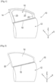
- THE figures 1 and 2 show doors 10 of motor vehicles.
- the door 10 comprises a lower frame 12 and an upper frame 14.
- the frame 14 has a general inverted U shape and defines with the frame 12 a space closed by a window 16.
- the window 16 is movable and can be moved from the high position in which it occupies the space of the frame 14 to a low position in which it is housed in the frame 12.
- the door 10 includes a seal or a set of seals intended to cooperate with the window 16 to ensure a seal between the window 16, on the one hand, and the frame 12 and the frame 14, on the other hand. This concerns waterproofing and dustproofing in particular.
- a first seal 18 extends along an upper edge of the frame 12 and is conventionally called a seal. When the window 16 moves, it rubs on the seal 18.
- Another seal 20 extends along the frame 14 and has a general U shape and is called a slide seal. The window 16 is engaged in the grooves of the seal 20 which guides the window during its movements and ensures support and peripheral sealing of the window when it is in the high position in the frame 14. The seal 20 is carried by the door 10 and therefore the opening.
- the door 10 includes a frame 12 and does not include an upper frame.
- the door 10 is also equipped with a seal 18 of the licker type.
- the window 16 cooperates with a seal 22 (shown in dotted lines) which is carried by a door frame of the vehicle.
- the seal 22 is here carried by the frame formed by the body of the vehicle.
- the subject of the present invention is a seal for a window of a vehicle, this seal being for example a seal chosen from seals 18, 20 and 22, that is to say a seal, a slide seal , a door frame seal.
- the particularity of the joint according to the invention is that it is heated.
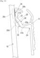
- FIG. 3 represents an embodiment of a heating joint according to the invention.
- the illustrated example represents a licker and it is clearly understood that the invention is not limited to this particular application.
- Seal 18 of the Figure 3 comprises a body 24 which has an elongated shape along an axis A and which is made of at least one material.
- the body 24 essentially comprises two parts, namely a first sealing part 24a and a second fixing part 24b.
- the sealing part 24a is made of a first material and comprises at least one elastically deformable lip 26.
- the first material is for example: TPE or TPV or soft rubber.
- the fixing part 24b is made of a second material and has a general inverted U shape. This fixing part 24b thus defines a groove 25 intended to receive a rebate of the door 10, and in particular of the upper edge of the frame 12.
- the second material is for example: polypropylene possibly loaded with for example glass fibers or talc, rubber of greater hardness, etc.
- the fixing part 24b can be reinforced and include an internal reinforcement 27, for example metallic.
- the body 24 can be produced by extrusion, its two parts 24a, 24b then being produced and secured together during the manufacture of the body.
- the seal 18 may include a trim 29 attached and fixed, for example on the fixing part 24b, in order to improve the aesthetics of the seal.
- the hubcap 29 is located to the left of the drawing and is intended to be located outside the vehicle.
- Lip 26 is located on the opposite and therefore interior side of the vehicle. The window 16 moves by rubbing or sliding on the lip 24.
- the lip 26 comprises a lower longitudinal edge 26a connecting to the rest of the body 24, and an upper longitudinal edge 26b which is free and curved towards the outside of the vehicle.
- the lip 26 comprises a surface 28 which extends between the edges 26a, 26b, on the interior side of the vehicle, and which is covered by a flocking 30.
- the flocking 30 also has an elongated shape along the axis A.
- the seal 18 further comprises at least one heating element extending along the axis A.
- This heating element is in the form of a multilayer film 34 which is interposed between the surface 28 and the flocking 30 in the example shown.
- Film 34 is relatively thin and flexible. As can be seen in the drawing, the flocking 30 can cover the entirety of the film 34 which is then invisible to the naked eye for a user of the vehicle or an operator who must mount the seal on the vehicle (cf. Figure 6 ). The flocking 30 covers a curved part of the edge 26b and the film 34 can also extend in this area and thus include a curved part in section (cf. figure 1 ).
- connection terminals 40 which are here located at a longitudinal end of the film 34 and can therefore be found at a longitudinal end of the joint 18.
- the terminals 40 are intended to be connected to a source of electrical energy.
- the terminals 40 each have a generally elongated shape and extend here perpendicular to the strips 36.
- the connection of the terminals 40 to the strips 36 can be made by overlapping the terminals 40 on the strips 36 or by overlapping the strips 36 on the terminals 40 ( cf. figure 4c ). To facilitate this overlap, the ends of the strips 36 connected to the terminals 40 can be at right angles.
- This film 34 preferably comprises a plastic support 42, for example PET.
- This support 42 is preferably thin and flexible.
- the strips 36 as well as the tracks 38 can be deposited, preferably by printing. Inks suitable for being printed on the support 42 of the film 34 are then used.
- the strips 36 it is for example possible to use a silver-based alloy.
- tracks 38 it It is for example possible to use a carbon-based ink, for example with a PTC effect.
- the strips 36 would then be printed on the support 42 and would partly overlap the tracks 38.
- the metal terminals 40 are preferably crimped on the lower strip 36 which possibly has a protrusion suitable for this crimping (cf. figure 4d ). They can alternatively be fixed with glue 44 on the support 42 and applied against the ends of the strips 36 (cf. figure 4c ). To maintain the assembly, protect it and insulate it electrically, a passivation layer 46 is preferably deposited on the entire support 42 and therefore covers the strips 36, the tracks 38, and the parts of the terminals 40 connected to the strips. . We therefore understand that the terminals 40 retain free ends 40a not covered by this passivation layer in order to authorize the electrical connection of the film to the circuit.
- FIG. 3 shows a possible position of the terminals 40.
- These terminals 40 preferably extend downwards when the seal 18 is in the mounted position on the door.
- These terminals 40 are preferably housed inside the frame 12 of the door 10 so that the connection to the circuit can take place inside the frame, that is to say in an area outside. protected from humidity.
- FIG. 5 shows the interior face of seal 18 of the Figure 3 , with the heating film 34 but without the flocking 30.
- the Figure 6 shows the complete seal 18 with its flocking and allows you to see that the film is entirely covered and therefore hidden and protected by the flocking 30, with the exception of the ends of the terminals 40.
- Flocking 30 is a layer of fibers, generally short and fine.
- the layer of fibers can be directly formed on the heating film 34.
- the flocking 30 can comprise a layer of fibers and a support, for example plastic, for this layer of fibers.
- the flocking 30 can be fixed by gluing on the heating film 34.
- a layer of glue 48 can be provided on the film 34, and in particular on the passivation layer 46.
- the glue layer 48 is then covered by the flocking 30, that is to say that the layer of fibers is deposited on this layer of glue 48, or the support carrying the layer of fibers is applied to this layer of glue 48.
- the film 34 may include another layer of glue 50 on its lower face opposite the flocking 30, in order to ensure its attachment to the surface 28.
- This layer of glue 50 is for example a layer of heat-activatable glue.
- glue 44, 48, 50 is understood to mean a composition with an evaporable solvent, but also by extension, a hot-melt and heat-reactivatable composition, or even a double-sided adhesive.
- the heating film 34 comprises several layers which are, from bottom to top, a layer of glue 50, a support 42, electroconductive strips 36, the tracks 38, the passivation layer 46, and the glue layer 48.
- FIG. 7 represents a variant embodiment of the heating film 34 which differs from that described above essentially in that its terminals 40 are located at a distance from the longitudinal ends of the film 34 and can therefore be found at a distance from the longitudinal ends of the seal 18.
- FIG 8 illustrates another alternative embodiment of the heating film 34 which comprises on the one hand two adjacent sections S1, S2 located next to each other and having independent operations.
- the first section S1 extends over half the length of the film 34 or the support 42 and can be activated independently of the second section S2 which extends over the remaining half of the film or the support.
- the two sections extend as an extension of each other.
- the first section S1 of the film comprises two electroconductive strips 36 between which extends at least one resistive track 38 and which are connected to two connection terminals 40.
- the second section S2 of the film comprises two other electroconductive strips 36 which extend respectively in the extension of the strips 36 of the first section S1 and between which extends at least one resistive track 38. These other strips 36 are also connected to two connection terminals 40.
- each of the sections S1, S2 comprises a single resistive track 38.
- This track 38 has a length substantially equal to the length of the strips 36.
- the track 38 therefore has a much greater length (and for example more than 50 times greater ) to its width.
- THE figures 10 and 11 show another alternative embodiment of the heating film 34 in which the tracks 38 have identical lengths L but are located at a distance (P1, P2) from each other, which varies. Near the longitudinal ends of the film 34, the pitch P1 which separates two consecutive tracks 38 is the smallest, and this pitch increases as we approach the middle of the film (P1 -> P2) where the terminals are located 40. Tracks 38 have identical widths.
- FIG. 12 show another alternative embodiment of the heating film 34 in which the tracks 38 have lengths (L1, L2) which vary and are separated from each other by a constant pitch (P). Near the longitudinal ends of the film 34, the tracks have the greatest length (L1), and this length decreases as we approach the middle of the film (L1 -> L2) where the terminals 40 are located.
- the tracks 38 have identical widths.
- the heating film could comprise several tracks powered by several pairs of electrical connection terminals. Each of the pairs would provide electrical power to one of the tracks.
- the terminals could be connected to the source of electrical energy by a control system which would be connected to a external or atmospheric temperature sensor of the vehicle.
- the system would, for example, be configured to activate heating when the temperature is below a certain threshold, for example 5°C, and to inhibit heating above this threshold.
- control system could be configured to control the heating according to a speed of movement of the window intended to cooperate with the seal so as to optimize the contact time between the seal and the window and thus defrosting the window.
- FIG 13 illustrates another alternative embodiment of a seal according to the invention in which the lip 26 supporting the heating film 34 comprises an integrated hinge 31a.
- This hinge 31a extends in the longitudinal direction and therefore parallel to the axis A. It separates the lip 26 into two longitudinal portions, here respectively upper 26c and lower 26d.
- the upper edge 26b of the lip 26 is curved as mentioned in the above. Its lower edge 26a is connected to the rest of the body 24 and can form another integrated longitudinal hinge 31b.
- the hinges 31a, and 31b are spaced apart and allow the lip to deform to best match the shape of the window 16 and optimize the contact surface with the window and therefore the defrosting capacity of the window. the window.
- the hinge 31a is formed by a thinning of the lip 26 or by a longitudinal groove 33.
- This groove 33 is formed on one face of the lip 26 opposite the surface 28.
- the surface 28 extends over at least one of these longitudinal portions 26c, 26d, and over both portions in the example shown.
- the flocking 30 thus extends over the two portions 26c, 26d in the example shown.
- the heating film 34 is located on at least one of these longitudinal portions 26c, 26d, and only on the portion 26c in the example shown.
- the flocking extends substantially from the upper edge 26b to the second hinge 31b.
- the seal would comprise two or more lips which would each be equipped with a heating element in the form of a film and which would be intended to cooperate with the same window.
- the film 34 is preferably configured and can be powered at an electrical power of less than 150W and which is for example between 10 and 100W. It can be configured to heat up to a temperature of between 1 and 100°C for an atmospheric temperature of, for example, between -40 and 10°C.
- the film 34 can equip several types of seal for vehicle windows.
- it before mounting the heating film on a joint, it can be rolled up and presented in the form of a reel.
- the coil may comprise a single heating film or a plurality of successive heating films arranged one after the other and which can be separated from each other by detachment or cutting for example.
- the heating films are produced independently of each other.
- the mounting of the heating film on a seal can be carried out directly on a seal manufacturing line or can be carried out on a particular seal for a new vehicle or for the replacement of a conventional vehicle seal with a heated seal.
Landscapes
- Engineering & Computer Science (AREA)
- Mechanical Engineering (AREA)
- Seal Device For Vehicle (AREA)
Applications Claiming Priority (1)
| Application Number | Priority Date | Filing Date | Title |
|---|---|---|---|
| FR2110423A FR3127724B1 (fr) | 2021-10-01 | 2021-10-01 | Joint d’etancheite chauffant pour une vitre d’un vehicule |
Publications (2)
| Publication Number | Publication Date |
|---|---|
| EP4159503A1 EP4159503A1 (fr) | 2023-04-05 |
| EP4159503B1 true EP4159503B1 (fr) | 2024-06-05 |
Family
ID=79269960
Family Applications (1)
| Application Number | Title | Priority Date | Filing Date |
|---|---|---|---|
| EP22197898.4A Active EP4159503B1 (fr) | 2021-10-01 | 2022-09-27 | Joint d etancheite chauffant pour une vitre d'un vehicule |
Country Status (5)
| Country | Link |
|---|---|
| US (1) | US12054037B2 (pl) |
| EP (1) | EP4159503B1 (pl) |
| ES (1) | ES2985527T3 (pl) |
| FR (1) | FR3127724B1 (pl) |
| PL (1) | PL4159503T3 (pl) |
Family Cites Families (12)
| Publication number | Priority date | Publication date | Assignee | Title |
|---|---|---|---|---|
| US5493815A (en) * | 1993-05-17 | 1996-02-27 | The Standard Products Company | Corrosion barrier for automotive weatherstrips |
| DE19651733A1 (de) | 1996-12-12 | 1998-06-18 | Metzeler Automotive Profiles | Beheizbarer Gummikörper |
| US6266925B1 (en) * | 1998-07-15 | 2001-07-31 | Bard E. Camerer | Weather stripping system with heating element for vehicles |
| FR2901187B1 (fr) * | 2006-05-18 | 2015-09-25 | Cooper Standard Automotive France S A | Joint d'etancheite de vitre avec brin lecheur moule |
| FR2975036B1 (fr) * | 2011-05-10 | 2013-05-17 | Hutchinson | Profile moule par multi-injection formant un joint d'etancheite ou un enjoliveur pour carrosserie de vehicule automobile, et son procede de fabrication. |
| US20130312330A1 (en) * | 2012-05-23 | 2013-11-28 | Faurecia Interior Systems, Inc. | Sealing arrangements for doors of motor vehicles and methods of making the same |
| EP3031645A1 (en) * | 2014-12-12 | 2016-06-15 | Continental Automotive GmbH | Seal and heating arrangement for a movable vehicle closure |
| US11019689B2 (en) * | 2015-06-15 | 2021-05-25 | J.W. Speaker Corporation | Lens heating systems and methods for an LED lighting system |
| JP2017024612A (ja) * | 2015-07-24 | 2017-02-02 | 西川ゴム工業株式会社 | 自動車用ウェザーストリップ |
| FR3062085B1 (fr) * | 2017-01-23 | 2021-07-16 | Valeo Systemes Dessuyage | Dispositif et procede de degivrage et desembuage de vitre de vehicule automobile |
| DE102018107099A1 (de) * | 2018-03-26 | 2019-09-26 | Volkswagen Aktiengesellschaft | Abdichteinrichtung zur Abdichtung eines Fenster-Schachtes eines Kraftfahrzeugs, Verfahren zur Herstellung einer Abdichteinrichtung und Kraftfahrzeug |
| CN110901354A (zh) * | 2018-09-14 | 2020-03-24 | 福特全球技术公司 | 用于机动车辆的车窗或车门的密封装置 |
-
2021
- 2021-10-01 FR FR2110423A patent/FR3127724B1/fr active Active
-
2022
- 2022-09-27 EP EP22197898.4A patent/EP4159503B1/fr active Active
- 2022-09-27 ES ES22197898T patent/ES2985527T3/es active Active
- 2022-09-27 PL PL22197898.4T patent/PL4159503T3/pl unknown
- 2022-09-29 US US17/936,530 patent/US12054037B2/en active Active
Also Published As
| Publication number | Publication date |
|---|---|
| FR3127724A1 (fr) | 2023-04-07 |
| PL4159503T3 (pl) | 2024-10-14 |
| FR3127724B1 (fr) | 2023-09-08 |
| EP4159503A1 (fr) | 2023-04-05 |
| ES2985527T3 (es) | 2024-11-06 |
| US20230103627A1 (en) | 2023-04-06 |
| US12054037B2 (en) | 2024-08-06 |
Similar Documents
| Publication | Publication Date | Title |
|---|---|---|
| EP0343046B1 (fr) | Joint d'entancheite, notamment pour glace mobile de vehicule automobile | |
| EP0217703B1 (fr) | Vitre d'automobile chauffable électrique | |
| FR2508267A1 (fr) | Procede pour monter un vitrage dans la baie d'une carrosserie ou pour l'en demonter et vitrage pour la realisation de ce procede | |
| EP0975045A1 (fr) | Vitrage à antenne pour véhicules automobiles | |
| EP3240358B1 (fr) | Glace de projecteur automobile avec électrodes métalliques surmoulées | |
| EP3230101B1 (fr) | Vitrage a joint profile, enjoliveur et noyau et procede de fabrication du vitrage | |
| FR2984258A1 (fr) | Dispositif de raccordement electrique et hydraulique pour un systeme d'approvisionnement et/ou de distribution en lave-glace | |
| EP3766677A1 (fr) | Procédé de fabrication d'un élément de carrosserie muni d'une piste conductrice | |
| CA2805401A1 (fr) | Adaptateur d'essuie-glace a contacts electriques | |
| EP4159503B1 (fr) | Joint d etancheite chauffant pour une vitre d'un vehicule | |
| WO2020169803A1 (fr) | Vitrage a clip de maintien pour piece de couverture | |
| EP1037758B1 (fr) | Bande auto-adhesive constituant par exemple un joint pour vehicule automobile | |
| EP3898303B1 (fr) | Vitrage a joint profile encapsule comportant une piece rapportee fixee au moyen d'un crochet | |
| WO2018100287A1 (fr) | Panneau pliable de garnissage interieur de vehicule automobile | |
| EP0276602A1 (fr) | Vitrage prêt à sa pose et son procédé de fabrication et de fixation | |
| FR3014388A1 (fr) | Procede de fabrication d'un element chauffant pour balai d'essuie-glace d'un vehicule | |
| FR2801017A1 (fr) | Mecanisme d'essuie-glace a balayage lineaire alterne comportant un rail de guidage perfectionne | |
| EP3595943B1 (fr) | Organe de flexion pour balai d'essuyage | |
| EP1107353A1 (fr) | Véhicule automobile avec système d'accès sélectif du type "mains libres" | |
| EP3315368B1 (fr) | Ensemble pour vehicule automobile comprenant un equipement automobile et un element piezo-electrique | |
| EP3523165A1 (fr) | Monture de support pour balai d'essuie-glace, balai d'essuie-glace et système d'essuyage associés | |
| WO2023222392A1 (fr) | Vitrage comportant plusieurs joints profiles, joint profile et procede de fabrication d'un tel vitrage | |
| FR3140019A1 (fr) | Vitrage comportant plusieurs joints profiles, joint profile et procede de fabrication d’un tel vitrage | |
| BE890747A (fr) | Panneau destine a etre assemble par collage et procede d'assemblage | |
| FR2766132A1 (fr) | Procede de montage d'un joint d'etancheite formant lecheur pour vitre coulissante de vehicule automobile, et joint d'etancheite pour la mise en oeuvre du procede |
Legal Events
| Date | Code | Title | Description |
|---|---|---|---|
| PUAI | Public reference made under article 153(3) epc to a published international application that has entered the european phase |
Free format text: ORIGINAL CODE: 0009012 |
|
| STAA | Information on the status of an ep patent application or granted ep patent |
Free format text: STATUS: THE APPLICATION HAS BEEN PUBLISHED |
|
| AK | Designated contracting states |
Kind code of ref document: A1 Designated state(s): AL AT BE BG CH CY CZ DE DK EE ES FI FR GB GR HR HU IE IS IT LI LT LU LV MC MK MT NL NO PL PT RO RS SE SI SK SM TR |
|
| STAA | Information on the status of an ep patent application or granted ep patent |
Free format text: STATUS: REQUEST FOR EXAMINATION WAS MADE |
|
| 17P | Request for examination filed |
Effective date: 20230921 |
|
| RBV | Designated contracting states (corrected) |
Designated state(s): AL AT BE BG CH CY CZ DE DK EE ES FI FR GB GR HR HU IE IS IT LI LT LU LV MC MK MT NL NO PL PT RO RS SE SI SK SM TR |
|
| GRAP | Despatch of communication of intention to grant a patent |
Free format text: ORIGINAL CODE: EPIDOSNIGR1 |
|
| STAA | Information on the status of an ep patent application or granted ep patent |
Free format text: STATUS: GRANT OF PATENT IS INTENDED |
|
| INTG | Intention to grant announced |
Effective date: 20240119 |
|
| GRAS | Grant fee paid |
Free format text: ORIGINAL CODE: EPIDOSNIGR3 |
|
| GRAA | (expected) grant |
Free format text: ORIGINAL CODE: 0009210 |
|
| STAA | Information on the status of an ep patent application or granted ep patent |
Free format text: STATUS: THE PATENT HAS BEEN GRANTED |
|
| AK | Designated contracting states |
Kind code of ref document: B1 Designated state(s): AL AT BE BG CH CY CZ DE DK EE ES FI FR GB GR HR HU IE IS IT LI LT LU LV MC MK MT NL NO PL PT RO RS SE SI SK SM TR |
|
| REG | Reference to a national code |
Ref country code: CH Ref legal event code: EP |
|
| REG | Reference to a national code |
Ref country code: DE Ref legal event code: R096 Ref document number: 602022003791 Country of ref document: DE |
|
| REG | Reference to a national code |
Ref country code: IE Ref legal event code: FG4D Free format text: LANGUAGE OF EP DOCUMENT: FRENCH |
|
| REG | Reference to a national code |
Ref country code: LT Ref legal event code: MG9D |
|
| PG25 | Lapsed in a contracting state [announced via postgrant information from national office to epo] |
Ref country code: BG Free format text: LAPSE BECAUSE OF FAILURE TO SUBMIT A TRANSLATION OF THE DESCRIPTION OR TO PAY THE FEE WITHIN THE PRESCRIBED TIME-LIMIT Effective date: 20240605 |
|
| REG | Reference to a national code |
Ref country code: NL Ref legal event code: MP Effective date: 20240605 |
|
| PG25 | Lapsed in a contracting state [announced via postgrant information from national office to epo] |
Ref country code: HR Free format text: LAPSE BECAUSE OF FAILURE TO SUBMIT A TRANSLATION OF THE DESCRIPTION OR TO PAY THE FEE WITHIN THE PRESCRIBED TIME-LIMIT Effective date: 20240605 Ref country code: FI Free format text: LAPSE BECAUSE OF FAILURE TO SUBMIT A TRANSLATION OF THE DESCRIPTION OR TO PAY THE FEE WITHIN THE PRESCRIBED TIME-LIMIT Effective date: 20240605 |
|
| PG25 | Lapsed in a contracting state [announced via postgrant information from national office to epo] |
Ref country code: GR Free format text: LAPSE BECAUSE OF FAILURE TO SUBMIT A TRANSLATION OF THE DESCRIPTION OR TO PAY THE FEE WITHIN THE PRESCRIBED TIME-LIMIT Effective date: 20240906 |
|
| PG25 | Lapsed in a contracting state [announced via postgrant information from national office to epo] |
Ref country code: LV Free format text: LAPSE BECAUSE OF FAILURE TO SUBMIT A TRANSLATION OF THE DESCRIPTION OR TO PAY THE FEE WITHIN THE PRESCRIBED TIME-LIMIT Effective date: 20240605 |
|
| PG25 | Lapsed in a contracting state [announced via postgrant information from national office to epo] |
Ref country code: NO Free format text: LAPSE BECAUSE OF FAILURE TO SUBMIT A TRANSLATION OF THE DESCRIPTION OR TO PAY THE FEE WITHIN THE PRESCRIBED TIME-LIMIT Effective date: 20240905 Ref country code: LV Free format text: LAPSE BECAUSE OF FAILURE TO SUBMIT A TRANSLATION OF THE DESCRIPTION OR TO PAY THE FEE WITHIN THE PRESCRIBED TIME-LIMIT Effective date: 20240605 Ref country code: HR Free format text: LAPSE BECAUSE OF FAILURE TO SUBMIT A TRANSLATION OF THE DESCRIPTION OR TO PAY THE FEE WITHIN THE PRESCRIBED TIME-LIMIT Effective date: 20240605 Ref country code: GR Free format text: LAPSE BECAUSE OF FAILURE TO SUBMIT A TRANSLATION OF THE DESCRIPTION OR TO PAY THE FEE WITHIN THE PRESCRIBED TIME-LIMIT Effective date: 20240906 Ref country code: FI Free format text: LAPSE BECAUSE OF FAILURE TO SUBMIT A TRANSLATION OF THE DESCRIPTION OR TO PAY THE FEE WITHIN THE PRESCRIBED TIME-LIMIT Effective date: 20240605 Ref country code: BG Free format text: LAPSE BECAUSE OF FAILURE TO SUBMIT A TRANSLATION OF THE DESCRIPTION OR TO PAY THE FEE WITHIN THE PRESCRIBED TIME-LIMIT Effective date: 20240605 Ref country code: RS Free format text: LAPSE BECAUSE OF FAILURE TO SUBMIT A TRANSLATION OF THE DESCRIPTION OR TO PAY THE FEE WITHIN THE PRESCRIBED TIME-LIMIT Effective date: 20240905 |
|
| REG | Reference to a national code |
Ref country code: ES Ref legal event code: FG2A Ref document number: 2985527 Country of ref document: ES Kind code of ref document: T3 Effective date: 20241106 |
|
| PG25 | Lapsed in a contracting state [announced via postgrant information from national office to epo] |
Ref country code: NL Free format text: LAPSE BECAUSE OF FAILURE TO SUBMIT A TRANSLATION OF THE DESCRIPTION OR TO PAY THE FEE WITHIN THE PRESCRIBED TIME-LIMIT Effective date: 20240605 |
|
| REG | Reference to a national code |
Ref country code: AT Ref legal event code: MK05 Ref document number: 1692226 Country of ref document: AT Kind code of ref document: T Effective date: 20240605 |
|
| PG25 | Lapsed in a contracting state [announced via postgrant information from national office to epo] |
Ref country code: NL Free format text: LAPSE BECAUSE OF FAILURE TO SUBMIT A TRANSLATION OF THE DESCRIPTION OR TO PAY THE FEE WITHIN THE PRESCRIBED TIME-LIMIT Effective date: 20240605 |
|
| P01 | Opt-out of the competence of the unified patent court (upc) registered |
Free format text: CASE NUMBER: APP_58745/2024 Effective date: 20241028 |
|
| PG25 | Lapsed in a contracting state [announced via postgrant information from national office to epo] |
Ref country code: PT Free format text: LAPSE BECAUSE OF FAILURE TO SUBMIT A TRANSLATION OF THE DESCRIPTION OR TO PAY THE FEE WITHIN THE PRESCRIBED TIME-LIMIT Effective date: 20241007 |
|
| PG25 | Lapsed in a contracting state [announced via postgrant information from national office to epo] |
Ref country code: PT Free format text: LAPSE BECAUSE OF FAILURE TO SUBMIT A TRANSLATION OF THE DESCRIPTION OR TO PAY THE FEE WITHIN THE PRESCRIBED TIME-LIMIT Effective date: 20241007 |
|
| PG25 | Lapsed in a contracting state [announced via postgrant information from national office to epo] |
Ref country code: EE Free format text: LAPSE BECAUSE OF FAILURE TO SUBMIT A TRANSLATION OF THE DESCRIPTION OR TO PAY THE FEE WITHIN THE PRESCRIBED TIME-LIMIT Effective date: 20240605 |
|
| PG25 | Lapsed in a contracting state [announced via postgrant information from national office to epo] |
Ref country code: AT Free format text: LAPSE BECAUSE OF FAILURE TO SUBMIT A TRANSLATION OF THE DESCRIPTION OR TO PAY THE FEE WITHIN THE PRESCRIBED TIME-LIMIT Effective date: 20240605 Ref country code: IS Free format text: LAPSE BECAUSE OF FAILURE TO SUBMIT A TRANSLATION OF THE DESCRIPTION OR TO PAY THE FEE WITHIN THE PRESCRIBED TIME-LIMIT Effective date: 20241005 |
|
| PG25 | Lapsed in a contracting state [announced via postgrant information from national office to epo] |
Ref country code: RO Free format text: LAPSE BECAUSE OF FAILURE TO SUBMIT A TRANSLATION OF THE DESCRIPTION OR TO PAY THE FEE WITHIN THE PRESCRIBED TIME-LIMIT Effective date: 20240605 Ref country code: SK Free format text: LAPSE BECAUSE OF FAILURE TO SUBMIT A TRANSLATION OF THE DESCRIPTION OR TO PAY THE FEE WITHIN THE PRESCRIBED TIME-LIMIT Effective date: 20240605 |
|
| PG25 | Lapsed in a contracting state [announced via postgrant information from national office to epo] |
Ref country code: SM Free format text: LAPSE BECAUSE OF FAILURE TO SUBMIT A TRANSLATION OF THE DESCRIPTION OR TO PAY THE FEE WITHIN THE PRESCRIBED TIME-LIMIT Effective date: 20240605 |
|
| PG25 | Lapsed in a contracting state [announced via postgrant information from national office to epo] |
Ref country code: SM Free format text: LAPSE BECAUSE OF FAILURE TO SUBMIT A TRANSLATION OF THE DESCRIPTION OR TO PAY THE FEE WITHIN THE PRESCRIBED TIME-LIMIT Effective date: 20240605 Ref country code: SK Free format text: LAPSE BECAUSE OF FAILURE TO SUBMIT A TRANSLATION OF THE DESCRIPTION OR TO PAY THE FEE WITHIN THE PRESCRIBED TIME-LIMIT Effective date: 20240605 Ref country code: RO Free format text: LAPSE BECAUSE OF FAILURE TO SUBMIT A TRANSLATION OF THE DESCRIPTION OR TO PAY THE FEE WITHIN THE PRESCRIBED TIME-LIMIT Effective date: 20240605 Ref country code: IS Free format text: LAPSE BECAUSE OF FAILURE TO SUBMIT A TRANSLATION OF THE DESCRIPTION OR TO PAY THE FEE WITHIN THE PRESCRIBED TIME-LIMIT Effective date: 20241005 Ref country code: EE Free format text: LAPSE BECAUSE OF FAILURE TO SUBMIT A TRANSLATION OF THE DESCRIPTION OR TO PAY THE FEE WITHIN THE PRESCRIBED TIME-LIMIT Effective date: 20240605 Ref country code: AT Free format text: LAPSE BECAUSE OF FAILURE TO SUBMIT A TRANSLATION OF THE DESCRIPTION OR TO PAY THE FEE WITHIN THE PRESCRIBED TIME-LIMIT Effective date: 20240605 |
|
| PG25 | Lapsed in a contracting state [announced via postgrant information from national office to epo] |
Ref country code: IT Free format text: LAPSE BECAUSE OF FAILURE TO SUBMIT A TRANSLATION OF THE DESCRIPTION OR TO PAY THE FEE WITHIN THE PRESCRIBED TIME-LIMIT Effective date: 20240605 |
|
| REG | Reference to a national code |
Ref country code: DE Ref legal event code: R097 Ref document number: 602022003791 Country of ref document: DE |
|
| REG | Reference to a national code |
Ref country code: DE Ref legal event code: R119 Ref document number: 602022003791 Country of ref document: DE |
|
| PLBE | No opposition filed within time limit |
Free format text: ORIGINAL CODE: 0009261 |
|
| STAA | Information on the status of an ep patent application or granted ep patent |
Free format text: STATUS: NO OPPOSITION FILED WITHIN TIME LIMIT |
|
| PG25 | Lapsed in a contracting state [announced via postgrant information from national office to epo] |
Ref country code: DK Free format text: LAPSE BECAUSE OF FAILURE TO SUBMIT A TRANSLATION OF THE DESCRIPTION OR TO PAY THE FEE WITHIN THE PRESCRIBED TIME-LIMIT Effective date: 20240605 |
|
| PG25 | Lapsed in a contracting state [announced via postgrant information from national office to epo] |
Ref country code: MC Free format text: LAPSE BECAUSE OF FAILURE TO SUBMIT A TRANSLATION OF THE DESCRIPTION OR TO PAY THE FEE WITHIN THE PRESCRIBED TIME-LIMIT Effective date: 20240605 |
|
| 26N | No opposition filed |
Effective date: 20250306 |
|
| PG25 | Lapsed in a contracting state [announced via postgrant information from national office to epo] |
Ref country code: LU Free format text: LAPSE BECAUSE OF NON-PAYMENT OF DUE FEES Effective date: 20240927 |
|
| PG25 | Lapsed in a contracting state [announced via postgrant information from national office to epo] |
Ref country code: DE Free format text: LAPSE BECAUSE OF NON-PAYMENT OF DUE FEES Effective date: 20250401 |
|
| REG | Reference to a national code |
Ref country code: BE Ref legal event code: MM Effective date: 20240930 |
|
| PG25 | Lapsed in a contracting state [announced via postgrant information from national office to epo] |
Ref country code: BE Free format text: LAPSE BECAUSE OF NON-PAYMENT OF DUE FEES Effective date: 20240930 |
|
| PG25 | Lapsed in a contracting state [announced via postgrant information from national office to epo] |
Ref country code: IE Free format text: LAPSE BECAUSE OF NON-PAYMENT OF DUE FEES Effective date: 20240927 |
|
| PG25 | Lapsed in a contracting state [announced via postgrant information from national office to epo] |
Ref country code: SE Free format text: LAPSE BECAUSE OF FAILURE TO SUBMIT A TRANSLATION OF THE DESCRIPTION OR TO PAY THE FEE WITHIN THE PRESCRIBED TIME-LIMIT Effective date: 20240605 |
|
| PGFP | Annual fee paid to national office [announced via postgrant information from national office to epo] |
Ref country code: PL Payment date: 20250919 Year of fee payment: 4 |
|
| PGFP | Annual fee paid to national office [announced via postgrant information from national office to epo] |
Ref country code: FR Payment date: 20250922 Year of fee payment: 4 |
|
| PGFP | Annual fee paid to national office [announced via postgrant information from national office to epo] |
Ref country code: CZ Payment date: 20250925 Year of fee payment: 4 |
|
| PG25 | Lapsed in a contracting state [announced via postgrant information from national office to epo] |
Ref country code: CY Free format text: LAPSE BECAUSE OF FAILURE TO SUBMIT A TRANSLATION OF THE DESCRIPTION OR TO PAY THE FEE WITHIN THE PRESCRIBED TIME-LIMIT; INVALID AB INITIO Effective date: 20220927 |
|
| PGFP | Annual fee paid to national office [announced via postgrant information from national office to epo] |
Ref country code: ES Payment date: 20251030 Year of fee payment: 4 |