EP4159259B1 - Blockiervorrichtung - Google Patents
Blockiervorrichtung Download PDFInfo
- Publication number
- EP4159259B1 EP4159259B1 EP22203019.9A EP22203019A EP4159259B1 EP 4159259 B1 EP4159259 B1 EP 4159259B1 EP 22203019 A EP22203019 A EP 22203019A EP 4159259 B1 EP4159259 B1 EP 4159259B1
- Authority
- EP
- European Patent Office
- Prior art keywords
- rotatable part
- blocking device
- blocking
- rotation
- recess
- Prior art date
- Legal status (The legal status is an assumption and is not a legal conclusion. Google has not performed a legal analysis and makes no representation as to the accuracy of the status listed.)
- Active
Links
Images
Classifications
-
- A—HUMAN NECESSITIES
- A61—MEDICAL OR VETERINARY SCIENCE; HYGIENE
- A61M—DEVICES FOR INTRODUCING MEDIA INTO, OR ONTO, THE BODY; DEVICES FOR TRANSDUCING BODY MEDIA OR FOR TAKING MEDIA FROM THE BODY; DEVICES FOR PRODUCING OR ENDING SLEEP OR STUPOR
- A61M15/00—Inhalators
-
- A—HUMAN NECESSITIES
- A61—MEDICAL OR VETERINARY SCIENCE; HYGIENE
- A61M—DEVICES FOR INTRODUCING MEDIA INTO, OR ONTO, THE BODY; DEVICES FOR TRANSDUCING BODY MEDIA OR FOR TAKING MEDIA FROM THE BODY; DEVICES FOR PRODUCING OR ENDING SLEEP OR STUPOR
- A61M11/00—Sprayers or atomisers specially adapted for therapeutic purposes
- A61M11/006—Sprayers or atomisers specially adapted for therapeutic purposes operated by applying mechanical pressure to the liquid to be sprayed or atomised
- A61M11/007—Syringe-type or piston-type sprayers or atomisers
-
- A—HUMAN NECESSITIES
- A61—MEDICAL OR VETERINARY SCIENCE; HYGIENE
- A61M—DEVICES FOR INTRODUCING MEDIA INTO, OR ONTO, THE BODY; DEVICES FOR TRANSDUCING BODY MEDIA OR FOR TAKING MEDIA FROM THE BODY; DEVICES FOR PRODUCING OR ENDING SLEEP OR STUPOR
- A61M15/00—Inhalators
- A61M15/0065—Inhalators with dosage or measuring devices
- A61M15/0068—Indicating or counting the number of dispensed doses or of remaining doses
- A61M15/0081—Locking means
-
- A—HUMAN NECESSITIES
- A61—MEDICAL OR VETERINARY SCIENCE; HYGIENE
- A61M—DEVICES FOR INTRODUCING MEDIA INTO, OR ONTO, THE BODY; DEVICES FOR TRANSDUCING BODY MEDIA OR FOR TAKING MEDIA FROM THE BODY; DEVICES FOR PRODUCING OR ENDING SLEEP OR STUPOR
- A61M15/00—Inhalators
- A61M15/009—Inhalators using medicine packages with incorporated spraying means, e.g. aerosol cans
-
- A—HUMAN NECESSITIES
- A61—MEDICAL OR VETERINARY SCIENCE; HYGIENE
- A61M—DEVICES FOR INTRODUCING MEDIA INTO, OR ONTO, THE BODY; DEVICES FOR TRANSDUCING BODY MEDIA OR FOR TAKING MEDIA FROM THE BODY; DEVICES FOR PRODUCING OR ENDING SLEEP OR STUPOR
- A61M2202/00—Special media to be introduced, removed or treated
- A61M2202/04—Liquids
-
- A—HUMAN NECESSITIES
- A61—MEDICAL OR VETERINARY SCIENCE; HYGIENE
- A61M—DEVICES FOR INTRODUCING MEDIA INTO, OR ONTO, THE BODY; DEVICES FOR TRANSDUCING BODY MEDIA OR FOR TAKING MEDIA FROM THE BODY; DEVICES FOR PRODUCING OR ENDING SLEEP OR STUPOR
- A61M2205/00—General characteristics of the apparatus
- A61M2205/27—General characteristics of the apparatus preventing use
- A61M2205/273—General characteristics of the apparatus preventing use preventing reuse, e.g. of disposables
-
- A—HUMAN NECESSITIES
- A61—MEDICAL OR VETERINARY SCIENCE; HYGIENE
- A61M—DEVICES FOR INTRODUCING MEDIA INTO, OR ONTO, THE BODY; DEVICES FOR TRANSDUCING BODY MEDIA OR FOR TAKING MEDIA FROM THE BODY; DEVICES FOR PRODUCING OR ENDING SLEEP OR STUPOR
- A61M2205/00—General characteristics of the apparatus
- A61M2205/27—General characteristics of the apparatus preventing use
- A61M2205/276—General characteristics of the apparatus preventing use preventing unwanted use
-
- A—HUMAN NECESSITIES
- A61—MEDICAL OR VETERINARY SCIENCE; HYGIENE
- A61M—DEVICES FOR INTRODUCING MEDIA INTO, OR ONTO, THE BODY; DEVICES FOR TRANSDUCING BODY MEDIA OR FOR TAKING MEDIA FROM THE BODY; DEVICES FOR PRODUCING OR ENDING SLEEP OR STUPOR
- A61M2205/00—General characteristics of the apparatus
- A61M2205/82—Internal energy supply devices
- A61M2205/8275—Mechanical
- A61M2205/8281—Mechanical spring operated
-
- B—PERFORMING OPERATIONS; TRANSPORTING
- B05—SPRAYING OR ATOMISING IN GENERAL; APPLYING FLUENT MATERIALS TO SURFACES, IN GENERAL
- B05B—SPRAYING APPARATUS; ATOMISING APPARATUS; NOZZLES
- B05B11/00—Single-unit hand-held apparatus in which flow of contents is produced by the muscular force of the operator at the moment of use
- B05B11/01—Single-unit hand-held apparatus in which flow of contents is produced by the muscular force of the operator at the moment of use characterised by the means producing the flow
- B05B11/10—Pump arrangements for transferring the contents from the container to a pump chamber by a sucking effect and forcing the contents out through the dispensing nozzle
- B05B11/109—Pump arrangements for transferring the contents from the container to a pump chamber by a sucking effect and forcing the contents out through the dispensing nozzle the dispensing stroke being affected by the stored energy of a spring
- B05B11/1091—Pump arrangements for transferring the contents from the container to a pump chamber by a sucking effect and forcing the contents out through the dispensing nozzle the dispensing stroke being affected by the stored energy of a spring being first hold in a loaded state by locking means or the like, then released
Definitions
- the invention relates to the field of inhalation devices for liquids.
- the invention relates to a blocking device for such an inhalation device.
- the inhalation device further comprises a tension or pressure spring, serving as a means for the storage of potential energy.
- a tension or pressure spring serving as a means for the storage of potential energy.
- US2015/0040890 describes a soft mist inhaler with a blocking mechanism that prevents the premature loading of a spring which stores potential energy by rotation of a rotatable part before the device is fully assembled: The rotation is blocked until a detachable part is connected to the housing and the housing is completely closed (claim 1, claim 15).
- US20130206136 describes an inhaler with a mechanism that prevents the operation of the device or its loading by rotating a rotatable part without first assembling the device completely.
- US2015/0320948 and DE10239443 (A1) disclose blocking mechanisms which block the further operation of an inhalation device after its designated life time (or after the designated life time of a cartridge inside the inhalation device).
- the device blocks further attempts to load the device and release a further dose of aerosol, regardless of whether or not residual amounts of liquid are still present in the liquid reservoir.
- EP 2 835 146 A1 US 2012/138713 A1 and WO 2004/022244 A1 further disclose inhalation devices with blocking mechanism.
- inhalation devices which exhibit improved blocking mechanisms which also prevent incorrect or undesirable manipulations by the user or patient during the life time of the inhaler, i.e. at other points of time during the repeated use of the device. For example, it is desirable to prevent the user from performing - or attempting to perform - more than one loading action in sequence without releasing any aerosol. This could lead to subsequent malfunction of the inhalation device.
- the device comprises a dose counter, it is likely that each loading cycle will be counted as a dosing, even though no dose was released to the patient or user. As a consequence, the inhaler (or the cartridge inside the inhaler) will not last for the entire period of time over which the prescribing physician intended to treat the respective patient.
- the inhalation device It is also desirable at any time during the regular use of the inhalation device to prevent the premature actuation of the release button. If the release button is pressed during performing the loading of the device, the loading motion can result in an undesired immediate emission of material through the nozzle, or in an unintended emission immediately at the end of the loading.
- the pressure is not sufficient for aerosol production (atomization)
- no aerosol, but liquid may emitted. Therefore, aerosol or liquid can spill and contaminate objects or persons, which is undesired.
- spilled liquid is no more available for its intended purpose. The liquid may contain active ingredients; thus, bystanders might be harmed by spilled liquid.
- the object of the invention is the provision of a device that comprises an improved mechanism for the prevention of incorrect use of the device during the time span of regular use, and which avoids or overcomes at least one of the drawbacks of the known art.
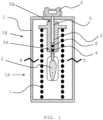
- an inhalation device for medically active liquids (F) for generation of an aerosol comprising a housing (1), inside this housing (1) a reservoir (2) for storing a liquid (F), a pumping device with a pumping chamber (3) for generation of a pressure inside said pumping chamber (3), wherein the pumping chamber (3) is fluidically connected with the reservoir (2), a riser pipe (5) which can be received with at least one reservoir-facing, interior end (5A) in said pumping chamber (3), and a nozzle (6) which is connected liquid-tight to an exterior end (5B) of the riser pipe (5), wherein the interior volume of the pumping chamber (3) is changeable by means of linear relative motion of the pumping chamber to the riser pipe (5).
- Said linear relative motion can be effected by a relative rotation of a rotatable part (1A) which is part of, or connected to, the housing (1) with respect to a second part (1B) of said housing (1), such that said relative rotation is converted into said linear relative motion by means of a gear mechanism.
- the inhalation device further comprises a means for the storage of potential energy (7) which is chargeable by means of said relative rotation, and wherein said energy is releasable to said pumping device when released by activation of a release means.
- the inhalation device comprises a blocking device (9) which is adapted to block rotation of the rotatable part (1A).
- This embodiment is further characterised in that the blocking device (9) is adapted to be moveable between a blocking position and a non-blocking position, and in that the blocking device is adapted to (a) move into the blocking position upon rotating the rotatable part (1A) by a predefined rotation angle, and (b) move into the non-blocking position upon activating the release means.
- the inhalation device preferably represents an inhaler from the class of so-called soft mist inhalers.
- Its pumping device (or pumping unit) serves for generation of a pressure inside the pumping chamber.
- the pumping chamber is fluidically connected with the at least one reservoir.
- a riser pipe which can be received with at least one reservoir-facing, interior end in said pumping chamber, serves for transporting the liquid from the reservoir to the pumping chamber.
- a nozzle which is connected liquid-tight to an exterior end of the riser pipe, servers for generation of the inhalable mist of fine liquid droplets.
- the nozzle is of the impingment type.
- the interior volume of the pumping chamber is changeable by means of linear relative motion of the pumping chamber to the riser pipe.
- said linear relative motion is achieved by a relative rotation of a rotatable part which is part of, or connected to, the housing with respect to a second part of said housing, and wherein the rotatable part and the second part are arranged such that said relative rotation is converted into said linear relative motion by means of a gear mechanism.
- the housing comprises two separate parts, and when holding these parts in different hands and rotating one of these parts relative to the other, a gear mechanism will convert the relative rotation into a linear motion which is used to build up a sufficiently high pressure in the pumping chamber.
- the pressure In order to produce a uniform mist, the pressure needs to be rather uniform as well during the time it is present. Since a person is not always capable of reproducibly provide such a uniform pressure by uniformly rotating the rotatable part of the housing, resulting in varying droplet sizes and emission times, a means for the (intermediate) storage of potential energy is provided which is chargeable by means of said relative rotation, wherein said energy is releasable to said pumping device when released by activation of a release means.
- the person in order to eliminate the influence of the person which uses the inhalation device on droplet formation, the person is only used for loading a means for storage of potential energy, such as a pressure or tension spring, by rotating the rotatable part relative to the second part, or vice-versa.
- a release means such as a button is activated, and the means for storage of potential energy releases its energy in form of a constant pressure to the pressure chamber.
- the inhalation device comprises a blocking mechanism which can block the rotation of the rotatable part.
- the blocking device is adapted to be moveable between a first position (also referred to as blocking position) and a second position (also referred to as non-blocking position).
- the blocking position and the non-blocking position are axial positions, meaning that the movement between these two positions is an axial movement.
- the blocking device is able to take a first position which is, with respect to the tip (or the bottom) of the inhalation device, further away from (or closer to) said tip (or bottom) than in a second position.
- This definition is particularly useful when the device has a distinct longitudinal axis, which is the case if the inhalation device has a longitudinal, e.g. cylindrical, shape.
- Another definition makes use of the rotation axis of the rotatable part; the two axial positions are along different locations of an axis which is parallel to said rotational axis.
- the latter definition is also usable for e.g. a spherical (ball shaped) inhalation device.
- the blocking device is designed to perform this movement repeatedly during the regular use or life time of the inhalation device, or over the use of a cartidge of liquid within the device.
- it is adapted to perform at least one movement from the first to the second position and at least one movement back from the second to the first position within each dosing event, also referred to as dosing cycle, which comprises the charging of the device and the release of a dose of aerosol to the user or patient.
- the blocking device is radially immobile. This means that the blocking device is unable to rotate relative to the second part which is part of, or connected to, the housing. At the same time, the rotatable part is capable of rotating relative to the blocking device. This allows for a construction wherein the blocking device can selectively block rotation of the rotatable part.
- the blocking device upon activation of the release means, can be pushed from the first position, or blocking position, to the second position, or non-blocking position, by means of a catch which is directly or indirectly fixed to the pumping chamber, such that it moves together with the movement of the pumping chamber, preferably also in an axial direction.
- a catch which is directly or indirectly fixed to the pumping chamber, such that it moves together with the movement of the pumping chamber, preferably also in an axial direction.
- the rotatable part has an axial recess configured to receive at least a part of the blocking device.
- the recess is configured and dimensioned such that, when said blocking device is at least partially received in said recess, the rotation of the rotatable part is blocked or nearly blocked, whereas when the blocking device is outside of said recess, the rotatable part is unblocked.
- the expression "nearly blocked” means that a minor rotational movement of the rotatable part is still possible even when the blocking device is positioned in the recess.
- Such a recess is easy to manufacture, and it is also particularly advantageous in that a blocking device held in a recess allows the provision of a particularly strong mechanical blocking mechanism.
- a blocking mechanism held in a recess allows the provision of a particularly strong mechanical blocking mechanism.
- a chamfer or the like can be provided that allows sliding out of the recess upon rotating the rotatable part which is part of, or connected to, the housing.
- the axial movement of the blocking device from the non-blocking position into its blocking position may be facilitated by the pressure exerted e.g. by compression spring or the like.
- the inhalation device comprises a rotatable part with two recesses.
- the two recesses have approximately the same dimensions, and they are preferably positioned apart from each other by a rotation angle of about 180°.
- the combined effects of the two blocking devices as described above would render the repeated regular use of the inhalation device safe and reliable, prevent the inadvertent emission of liquid or aerosol and ensure that the inhalation device will have its designated use time.
- the respective blocking devices could be adapted such that, within each dosing cycle, the user or patient initially performs a rotation movement such as to rate the rotatable part relative to the second part of the housing of the inhaler. During this rotation, the first blocking device is in its non-blocking position (such as to allow the rotation), while the second blocking device is in its blocking position, until a predetermined angle of rotations, such as 170° to 180°, has been reached.
- Said linear relative motion can be effected by a relative rotation of rotatable part 1A with respect to second part 1B.
- the relative rotation can be transferred by means of a gear mechanism (not shown) into said relative translational motion.
- a means for the storage of potential energy 7 is provided which is chargeable by means of said relative rotation, and said energy is releasable to said pumping device when released by activation of a release means (not shown).
- rotatable part 1A is connected to a co-rotatable part 1A' of the housing. Both parts 1A, 1A' are connected in a way such that when the co-rotatable (or “according") part 1A' is rotated, rotatable part 1A rotates as well.
- rotatable part 1A can be regarded as being a part of the housing 1.
- the second part 1B is also depicted. The gap between the inner wall of second part 1B and rotatable part 1A indicates that the second part 1B is configured to not co-rotate with rotatable part 1A (and co-rotatable part 1A').
- blocking device 9 is depicted.
- Said blocking device 9 is radially immobile, but axially mobile (vertical direction in the figure). Thus, it cannot rotate together with rotatable part 1A around a rotation axis R.
- the blocking device 9 blocks rotation of the rotatable part 1A, while in a second position (not shown), blocking device 9 does not block said rotatable part 1A.
- both positions are axial positions.
- rotatable part 1A has an axial recess 11 configured to receive the radially immobile blocking device 9 such that, when said blocking device 9 is at least partially received in said recess 11, rotation of the rotatable part 1A is mechanically blocked, whereas when the blocking device 9 is outside of said recess 11, the rotatable part 1A is unblocked and can rotate relative to the second part 1B.
- a catch 10 is present which can move together with the pumping chamber (not shown). It is recalled that an axial motion of the pumping chamber results in pressure generation. Thus, upon activation of the release means (not shown), blocking device 9 is pushed from the first position to the second position by said catch 10. Catch 10 is configured to fit in, and to axially move within, said recess 11.
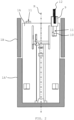
- the blocking device 9 is adapted to, after rotation of the rotatable part 1A for a predefined rotation angle (such as 180 degrees), automatically move back into the first position, thus blocking further rotation of the rotatable part 1A.
- a spring 12 is provided which forces the blocking device 9 downwards into recess 11 and against catch 10.
- the rotatable part 1A comprises two recesses 11, one of which is hidden by the rotatable part 1A in the figure.
- the blocking device can, after a rotation of e.g. 180 degrees, "fall” (or be forced by a second spring) into said second recess 11 which houses another catch 10 (not visible).
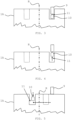
- blocking device 9 is, to a large extent, received by a first recess 11 of rotatable part 1A.
- Catch 10 and blocking device 9 are in a respective first position, wherein rotational movement (to the right and the left in the picture) of rotatable part 1A is almost entirely inhibited, since such motion is blocked by blocking device 9 due to its radial immobility.
- rotatable part 1A has rotated around rotation axis R, together with catch 10 (dashed arrow).
- Blocking device 9 slides along the upper edge of rotatable part 1A.
- catch 10 moves back from the second position towards the first position which will be reached, at the latest, when a full loading cycle (rotation of e.g. 180 degrees) is completed.
- blocking device 9 can be received once again in a recess; in the depicted embodiment, this will be the second recess drawn in dashed lines.
Landscapes
- Health & Medical Sciences (AREA)
- Engineering & Computer Science (AREA)
- Life Sciences & Earth Sciences (AREA)
- Public Health (AREA)
- Animal Behavior & Ethology (AREA)
- Veterinary Medicine (AREA)
- Anesthesiology (AREA)
- Biomedical Technology (AREA)
- Heart & Thoracic Surgery (AREA)
- Hematology (AREA)
- General Health & Medical Sciences (AREA)
- Bioinformatics & Cheminformatics (AREA)
- Pulmonology (AREA)
- Biophysics (AREA)
- Mechanical Engineering (AREA)
- Containers And Packaging Bodies Having A Special Means To Remove Contents (AREA)
- Infusion, Injection, And Reservoir Apparatuses (AREA)
- Lock And Its Accessories (AREA)
Claims (15)
- Verfahren zur Verhinderung der unerwünschten Abgabe von medizinisch wirksamer Flüssigkeit oder medizinisch wirksamem Aerosol aus einer Inhalationsvorrichtung,wobei die Inhalationsvorrichtung ein Gehäuse (1), in diesem Gehäuse (1) einen Vorratsbehälter (2) zur Lagerung einer Flüssigkeit (F), eine Pumpvorrichtung mit einer Pumpkammer (3) zur Erzeugung eines Drucks in der Pumpkammer (3), wobei die Pumpkammer (3) fluidisch mit dem Vorratsbehälter (2) verbunden ist, ein Steigrohr (5), das mit mindestens einem dem Vorratsbehälter zugewandten inneren Ende (5A) in der Pumpkammer (3) aufgenommen ist, und eine Düse (6) umfasst, die flüssigkeitsdicht mit einem äußeren Ende (5B) des Steigrohrs (5) verbunden ist, wobei das Innenvolumen der Pumpkammer (3) durch lineare Relativbewegung der Pumpkammer zu dem Steigrohr (5) veränderbar ist,wobei die lineare Relativbewegung durch eine Relativdrehung eines drehbaren Teils (1A), der Teil des Gehäuses (1) oder mit diesem verbunden ist, in Bezug auf einen zweiten Teil (1B) des Gehäuses (1) bewirkt wird,und wobei ein Mittel (7) zum Speichern von potenzieller Energie vorgesehen ist, das durch die Relativdrehung geladen wird und das die Energie an den Pumpmechanismus freigibt, wenn es durch Aktivieren eines Freigabemittels freigegeben wird,dadurch gekennzeichnet, dass(i) die Aktivierung des Freigabemittels und/oder das Freigeben des Mittels (7) zum Speichern von potenzieller Energie während des Drehens des drehbaren Teils (1A) oder während des Ladens des Mittels (7) zum Speichern von potenzieller Energie blockiert werden und/oder(ii) das Laden des Mittels (7) zum Speichern potenzieller Energie und/oder das Drehen des drehbaren Teils (1A) bei Aktivierung des Freigabemittels blockiert werden.
- Verfahren nach Anspruch 1, wobei für das Blockieren eine Blockiervorrichtung (9) bereitgestellt wird.
- Verfahren nach Anspruch 2, wobei die Blockiervorrichtung (9) radial unbeweglich ist.
- Verfahren nach Anspruch 2 oder 3, wobei sich die Blockiervorrichtung (9) aus einer ersten Position, in der sie die Drehung des drehbaren Teils (1A) blockiert, in eine zweite Position bewegt, in der sie die Drehung des drehbaren Teils (1A) freigibt.
- Verfahren nach Anspruch 4, wobei die Blockierposition und die Nichtblockierposition axiale Positionen sind.
- Verfahren nach Anspruch 4 oder 5, wobei sich die Blockiervorrichtung (9) nach dem Drehen des drehbaren Teils (1A) um einen vordefinierten Winkel, wodurch die Inhalationsvorrichtung für eine weitere Dosis neu geladen wird, aus der zweiten Position in die erste Position zurückbewegt.
- Verfahren nach Anspruch 6, wobei der vordefinierte Winkel 180 Grad beträgt.
- Verfahren nach einem der Ansprüche 2 bis 7, wobei zum Aktivieren des Freigabemittels und/oder zum Freigeben des Mittels (7) zum Speichern von potenzieller Energie eine Klinke (10) vorgesehen ist, die entlang einer in dem drehbaren Teil (1A) ausgebildeten axialen Aussparung gleitet und die Blockiervorrichtung (9) aus der ersten Position in die zweite Position schiebt.
- Verfahren nach Anspruch 8, wobei die Klinke (10) an der Pumpkammer (3) befestigt ist und/oder sich zusammen mit dieser bewegen kann.
- Verfahren nach einem der Ansprüche 2 bis 9, wobei der drehbare Teil (1A) eine axiale Aussparung (11) aufweist, die zur Aufnahme mindestens eines Teils der Blockiervorrichtung (9) ausgestaltet ist, so dass eine Drehung des drehbaren Teils (1A) blockiert oder nahezu blockiert wird, wenn die Blockiervorrichtung (9) mindestens teilweise in der Aussparung (11) aufgenommen ist, während der drehbare Teil (1A) freigegeben wird, wenn sich die Blockiervorrichtung (9) außerhalb der Aussparung (11) befindet.
- Verfahren nach Anspruch 10, wobei die Umfangsabmessung der Aussparung (11) größer als die der Blockiervorrichtung (9) ist, um eine begrenzte weitere Drehung des drehbaren Teils (1A) bei der Aufnahme der Blockiervorrichtung (9) in der Aussparung (11) zu gestatten, bevor die Drehung des drehbaren Teils (9) vollständig blockiert wird.
- Verfahren nach Anspruch 11, wobei die begrenzte weitere Drehung einem Drehwinkel von höchstens etwa 10° entspricht.
- Verfahren nach einem der Ansprüche 10 bis 12, wobei die Klinke (10) dazu ausgestaltet ist, (i) in die Aussparung (11) zu passen und (ii) sich axial in der Aussparung (11) zu bewegen.
- Verfahren nach einem der Ansprüche 10 bis 13, wobei der drehbare Teil (1A) zwei Aussparungen (11) umfasst.
- Verfahren nach Anspruch 14, wobei die beiden Aussparungen um einen Drehwinkel von etwa 180° voneinander beabstandet angeordnet sind.
Applications Claiming Priority (4)
| Application Number | Priority Date | Filing Date | Title |
|---|---|---|---|
| US201762610058P | 2017-12-22 | 2017-12-22 | |
| EP17210392 | 2017-12-22 | ||
| EP18826083.0A EP3727533B1 (de) | 2017-12-22 | 2018-12-22 | Blockierungsvorrichtung |
| PCT/EP2018/086834 WO2019122451A1 (en) | 2017-12-22 | 2018-12-22 | Blocking device |
Related Parent Applications (2)
| Application Number | Title | Priority Date | Filing Date |
|---|---|---|---|
| PCT/EP2018/086834 Previously-Filed-Application WO2019122451A1 (en) | 2017-12-22 | 2018-12-22 | Blocking device |
| EP18826083.0A Division EP3727533B1 (de) | 2017-12-22 | 2018-12-22 | Blockierungsvorrichtung |
Publications (2)
| Publication Number | Publication Date |
|---|---|
| EP4159259A1 EP4159259A1 (de) | 2023-04-05 |
| EP4159259B1 true EP4159259B1 (de) | 2025-03-26 |
Family
ID=64870522
Family Applications (2)
| Application Number | Title | Priority Date | Filing Date |
|---|---|---|---|
| EP22203019.9A Active EP4159259B1 (de) | 2017-12-22 | 2018-12-22 | Blockiervorrichtung |
| EP18826083.0A Active EP3727533B1 (de) | 2017-12-22 | 2018-12-22 | Blockierungsvorrichtung |
Family Applications After (1)
| Application Number | Title | Priority Date | Filing Date |
|---|---|---|---|
| EP18826083.0A Active EP3727533B1 (de) | 2017-12-22 | 2018-12-22 | Blockierungsvorrichtung |
Country Status (7)
| Country | Link |
|---|---|
| US (2) | US11717622B2 (de) |
| EP (2) | EP4159259B1 (de) |
| CN (1) | CN111526909B (de) |
| DK (2) | DK3727533T3 (de) |
| ES (2) | ES2936473T3 (de) |
| PL (1) | PL4159259T3 (de) |
| WO (1) | WO2019122451A1 (de) |
Families Citing this family (3)
| Publication number | Priority date | Publication date | Assignee | Title |
|---|---|---|---|---|
| US11612704B2 (en) * | 2017-04-28 | 2023-03-28 | Softhale Nv | Inhalation device and method |
| EP4159259B1 (de) * | 2017-12-22 | 2025-03-26 | invoX Belgium NV | Blockiervorrichtung |
| JP2024525864A (ja) | 2021-07-20 | 2024-07-12 | インヴォックス ベルジアム エヌヴイ | 計数・阻止アセンブリを伴う吸入装置システム |
Family Cites Families (17)
| Publication number | Priority date | Publication date | Assignee | Title |
|---|---|---|---|---|
| SG45171A1 (en) | 1990-03-21 | 1998-01-16 | Boehringer Ingelheim Int | Atomising devices and methods |
| DE10239443A1 (de) | 2002-08-28 | 2004-03-11 | Boehringer Ingelheim International Gmbh | Blockiervorrichtung für ein Sperrspannwerk mit federbetätigtem Abtrieb |
| US7396341B2 (en) * | 2002-08-28 | 2008-07-08 | Boehringer Ingelheim International Gmbh | Blocking device for a locking stressing mechanism having a spring-actuated output drive device |
| JP2005537834A (ja) * | 2002-09-05 | 2005-12-15 | ベーリンガー インゲルハイム ファルマ ゲゼルシャフト ミット ベシュレンクテル ハフツング ウント コンパニー コマンディトゲゼルシャフト | 液体小出し装置、これに適した容器カートリッジ及び液体小出し装置と容器カートリッジとを備えたシステム |
| US7621266B2 (en) * | 2003-01-14 | 2009-11-24 | Boehringer Ingelheim International Gmbh | Nozzle-system for a dispenser for fluids consisting of a nozzle and a nozzle-holder and/or screw cap |
| FR2854878B1 (fr) | 2003-05-15 | 2006-03-31 | Valois Sas | Distributeur de produit fluide. |
| DE102004009434A1 (de) * | 2004-02-24 | 2005-12-15 | Boehringer Ingelheim International Gmbh | Zerstäuber |
| EP1917108B1 (de) * | 2005-08-24 | 2012-10-03 | Boehringer Ingelheim International GmbH | Einen zähler und eine betriebsendsperre umfassender zerstäuber |
| US10011906B2 (en) * | 2009-03-31 | 2018-07-03 | Beohringer Ingelheim International Gmbh | Method for coating a surface of a component |
| WO2011160932A1 (en) | 2010-06-24 | 2011-12-29 | Boehringer Ingelheim International Gmbh | Nebulizer |
| CN104903213B (zh) * | 2012-11-14 | 2017-11-24 | 维实洛克分配系统公司 | 儿童安全泵 |
| PL2835146T3 (pl) | 2013-08-09 | 2021-04-06 | Boehringer Ingelheim International Gmbh | Nebulizator |
| EP3030298B1 (de) | 2013-08-09 | 2017-10-11 | Boehringer Ingelheim International GmbH | Vernebler |
| HRP20201987T1 (hr) * | 2013-08-20 | 2021-02-05 | Boehringer Ingelheim Vetmedica Gmbh | Inhalator |
| AU2015257878B2 (en) | 2014-05-07 | 2019-08-08 | Boehringer Ingelheim International Gmbh | Container, nebulizer and use |
| BR112016023719B1 (pt) | 2014-05-07 | 2021-12-21 | Boehringer Ingelheim International Gmbh | Nebulizador para um fluido e recipiente para um nebulizador |
| EP4159259B1 (de) * | 2017-12-22 | 2025-03-26 | invoX Belgium NV | Blockiervorrichtung |
-
2018
- 2018-12-22 EP EP22203019.9A patent/EP4159259B1/de active Active
- 2018-12-22 CN CN201880083323.8A patent/CN111526909B/zh active Active
- 2018-12-22 ES ES18826083T patent/ES2936473T3/es active Active
- 2018-12-22 DK DK18826083.0T patent/DK3727533T3/da active
- 2018-12-22 DK DK22203019.9T patent/DK4159259T3/da active
- 2018-12-22 EP EP18826083.0A patent/EP3727533B1/de active Active
- 2018-12-22 PL PL22203019.9T patent/PL4159259T3/pl unknown
- 2018-12-22 ES ES22203019T patent/ES3033076T3/es active Active
- 2018-12-22 US US16/955,794 patent/US11717622B2/en active Active
- 2018-12-22 WO PCT/EP2018/086834 patent/WO2019122451A1/en not_active Ceased
-
2023
- 2023-06-20 US US18/337,453 patent/US12502493B2/en active Active
Also Published As
| Publication number | Publication date |
|---|---|
| EP4159259A1 (de) | 2023-04-05 |
| ES3033076T3 (en) | 2025-07-30 |
| US20200316323A1 (en) | 2020-10-08 |
| US20240024593A1 (en) | 2024-01-25 |
| EP3727533B1 (de) | 2022-11-16 |
| US11717622B2 (en) | 2023-08-08 |
| EP3727533A1 (de) | 2020-10-28 |
| DK4159259T3 (da) | 2025-06-23 |
| US12502493B2 (en) | 2025-12-23 |
| CN111526909B (zh) | 2023-07-25 |
| PL4159259T3 (pl) | 2025-08-18 |
| CN111526909A (zh) | 2020-08-11 |
| DK3727533T3 (da) | 2023-02-06 |
| WO2019122451A1 (en) | 2019-06-27 |
| ES2936473T3 (es) | 2023-03-17 |
Similar Documents
| Publication | Publication Date | Title |
|---|---|---|
| US12502493B2 (en) | Blocking device | |
| US20200268978A1 (en) | Delivery Device | |
| AU730797B2 (en) | Device of miniaturised construction for producing high pressure in a fluid to be atomised | |
| JP3513604B2 (ja) | 薬剤吸入療法のための粉末噴流分与器 | |
| EP2104527B1 (de) | Vorrichtung zur abgabe von medikamenten | |
| US7396341B2 (en) | Blocking device for a locking stressing mechanism having a spring-actuated output drive device | |
| CA2497059C (en) | Blocking device for a locking-stressing-mechanism having a spring-actuated output drive device | |
| JP6900372B2 (ja) | ネブライザ及び容器 | |
| EP3993857B1 (de) | Tragbarer inhalator | |
| US20240382701A1 (en) | Inhalation device system with a counting and blocking assembly | |
| TWI819028B (zh) | 改進的吸入設備及通過吸入設備產生氣溶膠劑的方法 | |
| CN115038481A (zh) | 具有通过活塞杆与导杆之间的螺纹方式结合的药筒药物排放结构的给药调节装置 | |
| HK40032699A (en) | Blocking device | |
| HK40032699B (en) | Blocking device | |
| HK40046043A (en) | Improved inhalation device | |
| HK40046043B (en) | Improved inhalation device |
Legal Events
| Date | Code | Title | Description |
|---|---|---|---|
| PUAI | Public reference made under article 153(3) epc to a published international application that has entered the european phase |
Free format text: ORIGINAL CODE: 0009012 |
|
| STAA | Information on the status of an ep patent application or granted ep patent |
Free format text: STATUS: THE APPLICATION HAS BEEN PUBLISHED |
|
| AC | Divisional application: reference to earlier application |
Ref document number: 3727533 Country of ref document: EP Kind code of ref document: P |
|
| AK | Designated contracting states |
Kind code of ref document: A1 Designated state(s): AL AT BE BG CH CY CZ DE DK EE ES FI FR GB GR HR HU IE IS IT LI LT LU LV MC MK MT NL NO PL PT RO RS SE SI SK SM TR |
|
| P01 | Opt-out of the competence of the unified patent court (upc) registered |
Effective date: 20230529 |
|
| REG | Reference to a national code |
Ref country code: HK Ref legal event code: DE Ref document number: 40088747 Country of ref document: HK |
|
| STAA | Information on the status of an ep patent application or granted ep patent |
Free format text: STATUS: REQUEST FOR EXAMINATION WAS MADE |
|
| 17P | Request for examination filed |
Effective date: 20231005 |
|
| RBV | Designated contracting states (corrected) |
Designated state(s): AL AT BE BG CH CY CZ DE DK EE ES FI FR GB GR HR HU IE IS IT LI LT LU LV MC MK MT NL NO PL PT RO RS SE SI SK SM TR |
|
| RAP3 | Party data changed (applicant data changed or rights of an application transferred) |
Owner name: INVOX BELGIUM NV |
|
| GRAP | Despatch of communication of intention to grant a patent |
Free format text: ORIGINAL CODE: EPIDOSNIGR1 |
|
| STAA | Information on the status of an ep patent application or granted ep patent |
Free format text: STATUS: GRANT OF PATENT IS INTENDED |
|
| RIC1 | Information provided on ipc code assigned before grant |
Ipc: B05B 11/00 20230101ALN20241009BHEP Ipc: A61M 11/00 20060101ALI20241009BHEP Ipc: A61M 15/00 20060101AFI20241009BHEP |
|
| INTG | Intention to grant announced |
Effective date: 20241025 |
|
| GRAS | Grant fee paid |
Free format text: ORIGINAL CODE: EPIDOSNIGR3 |
|
| GRAA | (expected) grant |
Free format text: ORIGINAL CODE: 0009210 |
|
| STAA | Information on the status of an ep patent application or granted ep patent |
Free format text: STATUS: THE PATENT HAS BEEN GRANTED |
|
| AC | Divisional application: reference to earlier application |
Ref document number: 3727533 Country of ref document: EP Kind code of ref document: P |
|
| AK | Designated contracting states |
Kind code of ref document: B1 Designated state(s): AL AT BE BG CH CY CZ DE DK EE ES FI FR GB GR HR HU IE IS IT LI LT LU LV MC MK MT NL NO PL PT RO RS SE SI SK SM TR |
|
| REG | Reference to a national code |
Ref country code: GB Ref legal event code: FG4D |
|
| REG | Reference to a national code |
Ref country code: CH Ref legal event code: EP |
|
| REG | Reference to a national code |
Ref country code: DE Ref legal event code: R096 Ref document number: 602018080631 Country of ref document: DE |
|
| REG | Reference to a national code |
Ref country code: IE Ref legal event code: FG4D |
|
| REG | Reference to a national code |
Ref country code: PT Ref legal event code: SC4A Ref document number: 4159259 Country of ref document: PT Date of ref document: 20250530 Kind code of ref document: T Free format text: AVAILABILITY OF NATIONAL TRANSLATION Effective date: 20250526 |
|
| REG | Reference to a national code |
Ref country code: NL Ref legal event code: FP |
|
| REG | Reference to a national code |
Ref country code: DK Ref legal event code: T3 Effective date: 20250616 |
|
| PG25 | Lapsed in a contracting state [announced via postgrant information from national office to epo] |
Ref country code: RS Free format text: LAPSE BECAUSE OF FAILURE TO SUBMIT A TRANSLATION OF THE DESCRIPTION OR TO PAY THE FEE WITHIN THE PRESCRIBED TIME-LIMIT Effective date: 20250626 |
|
| PG25 | Lapsed in a contracting state [announced via postgrant information from national office to epo] |
Ref country code: FI Free format text: LAPSE BECAUSE OF FAILURE TO SUBMIT A TRANSLATION OF THE DESCRIPTION OR TO PAY THE FEE WITHIN THE PRESCRIBED TIME-LIMIT Effective date: 20250326 |
|
| REG | Reference to a national code |
Ref country code: SE Ref legal event code: TRGR |
|
| REG | Reference to a national code |
Ref country code: LT Ref legal event code: MG9D |
|
| PG25 | Lapsed in a contracting state [announced via postgrant information from national office to epo] |
Ref country code: NO Free format text: LAPSE BECAUSE OF FAILURE TO SUBMIT A TRANSLATION OF THE DESCRIPTION OR TO PAY THE FEE WITHIN THE PRESCRIBED TIME-LIMIT Effective date: 20250626 |
|
| PG25 | Lapsed in a contracting state [announced via postgrant information from national office to epo] |
Ref country code: HR Free format text: LAPSE BECAUSE OF FAILURE TO SUBMIT A TRANSLATION OF THE DESCRIPTION OR TO PAY THE FEE WITHIN THE PRESCRIBED TIME-LIMIT Effective date: 20250326 |
|
| PG25 | Lapsed in a contracting state [announced via postgrant information from national office to epo] |
Ref country code: LV Free format text: LAPSE BECAUSE OF FAILURE TO SUBMIT A TRANSLATION OF THE DESCRIPTION OR TO PAY THE FEE WITHIN THE PRESCRIBED TIME-LIMIT Effective date: 20250326 |
|
| PG25 | Lapsed in a contracting state [announced via postgrant information from national office to epo] |
Ref country code: GR Free format text: LAPSE BECAUSE OF FAILURE TO SUBMIT A TRANSLATION OF THE DESCRIPTION OR TO PAY THE FEE WITHIN THE PRESCRIBED TIME-LIMIT Effective date: 20250627 Ref country code: BG Free format text: LAPSE BECAUSE OF FAILURE TO SUBMIT A TRANSLATION OF THE DESCRIPTION OR TO PAY THE FEE WITHIN THE PRESCRIBED TIME-LIMIT Effective date: 20250326 |
|
| REG | Reference to a national code |
Ref country code: ES Ref legal event code: FG2A Ref document number: 3033076 Country of ref document: ES Kind code of ref document: T3 Effective date: 20250730 |
|
| REG | Reference to a national code |
Ref country code: AT Ref legal event code: MK05 Ref document number: 1778444 Country of ref document: AT Kind code of ref document: T Effective date: 20250326 |
|
| PG25 | Lapsed in a contracting state [announced via postgrant information from national office to epo] |
Ref country code: SM Free format text: LAPSE BECAUSE OF FAILURE TO SUBMIT A TRANSLATION OF THE DESCRIPTION OR TO PAY THE FEE WITHIN THE PRESCRIBED TIME-LIMIT Effective date: 20250326 |
|
| PG25 | Lapsed in a contracting state [announced via postgrant information from national office to epo] |
Ref country code: AT Free format text: LAPSE BECAUSE OF FAILURE TO SUBMIT A TRANSLATION OF THE DESCRIPTION OR TO PAY THE FEE WITHIN THE PRESCRIBED TIME-LIMIT Effective date: 20250326 |
|
| PG25 | Lapsed in a contracting state [announced via postgrant information from national office to epo] |
Ref country code: EE Free format text: LAPSE BECAUSE OF FAILURE TO SUBMIT A TRANSLATION OF THE DESCRIPTION OR TO PAY THE FEE WITHIN THE PRESCRIBED TIME-LIMIT Effective date: 20250326 |
|
| PG25 | Lapsed in a contracting state [announced via postgrant information from national office to epo] |
Ref country code: RO Free format text: LAPSE BECAUSE OF FAILURE TO SUBMIT A TRANSLATION OF THE DESCRIPTION OR TO PAY THE FEE WITHIN THE PRESCRIBED TIME-LIMIT Effective date: 20250326 |
|
| PG25 | Lapsed in a contracting state [announced via postgrant information from national office to epo] |
Ref country code: SK Free format text: LAPSE BECAUSE OF FAILURE TO SUBMIT A TRANSLATION OF THE DESCRIPTION OR TO PAY THE FEE WITHIN THE PRESCRIBED TIME-LIMIT Effective date: 20250326 |
|
| PG25 | Lapsed in a contracting state [announced via postgrant information from national office to epo] |
Ref country code: IS Free format text: LAPSE BECAUSE OF FAILURE TO SUBMIT A TRANSLATION OF THE DESCRIPTION OR TO PAY THE FEE WITHIN THE PRESCRIBED TIME-LIMIT Effective date: 20250726 |
|
| REG | Reference to a national code |
Ref country code: CH Ref legal event code: U11 Free format text: ST27 STATUS EVENT CODE: U-0-0-U10-U11 (AS PROVIDED BY THE NATIONAL OFFICE) Effective date: 20260101 |
|
| REG | Reference to a national code |
Ref country code: DE Ref legal event code: R097 Ref document number: 602018080631 Country of ref document: DE |
|
| PGFP | Annual fee paid to national office [announced via postgrant information from national office to epo] |
Ref country code: DE Payment date: 20251211 Year of fee payment: 8 |
|
| PGFP | Annual fee paid to national office [announced via postgrant information from national office to epo] |
Ref country code: GB Payment date: 20251219 Year of fee payment: 8 |
|
| PGFP | Annual fee paid to national office [announced via postgrant information from national office to epo] |
Ref country code: PT Payment date: 20251211 Year of fee payment: 8 |
|
| PGFP | Annual fee paid to national office [announced via postgrant information from national office to epo] |
Ref country code: IT Payment date: 20251223 Year of fee payment: 8 Ref country code: DK Payment date: 20251224 Year of fee payment: 8 |
|
| PGFP | Annual fee paid to national office [announced via postgrant information from national office to epo] |
Ref country code: NL Payment date: 20251219 Year of fee payment: 8 Ref country code: FR Payment date: 20251229 Year of fee payment: 8 |
|
| PGFP | Annual fee paid to national office [announced via postgrant information from national office to epo] |
Ref country code: TR Payment date: 20251217 Year of fee payment: 8 Ref country code: BE Payment date: 20251219 Year of fee payment: 8 |
|
| PGFP | Annual fee paid to national office [announced via postgrant information from national office to epo] |
Ref country code: SE Payment date: 20251219 Year of fee payment: 8 |
|
| PG25 | Lapsed in a contracting state [announced via postgrant information from national office to epo] |
Ref country code: CZ Free format text: LAPSE BECAUSE OF FAILURE TO SUBMIT A TRANSLATION OF THE DESCRIPTION OR TO PAY THE FEE WITHIN THE PRESCRIBED TIME-LIMIT Effective date: 20250326 |
|
| PGFP | Annual fee paid to national office [announced via postgrant information from national office to epo] |
Ref country code: IE Payment date: 20251219 Year of fee payment: 8 |
|
| PGFP | Annual fee paid to national office [announced via postgrant information from national office to epo] |
Ref country code: PL Payment date: 20251212 Year of fee payment: 8 |
|
| PLBE | No opposition filed within time limit |
Free format text: ORIGINAL CODE: 0009261 |
|
| STAA | Information on the status of an ep patent application or granted ep patent |
Free format text: STATUS: NO OPPOSITION FILED WITHIN TIME LIMIT |
|
| REG | Reference to a national code |
Ref country code: CH Ref legal event code: L10 Free format text: ST27 STATUS EVENT CODE: U-0-0-L10-L00 (AS PROVIDED BY THE NATIONAL OFFICE) Effective date: 20260211 |
|
| 26N | No opposition filed |
Effective date: 20260105 |
|
| PGFP | Annual fee paid to national office [announced via postgrant information from national office to epo] |
Ref country code: ES Payment date: 20260130 Year of fee payment: 8 |