EP4159134B1 - Verriegelungsanordnung für ct-detektionsvorrichtung und ct-detektionsvorrichtung - Google Patents
Verriegelungsanordnung für ct-detektionsvorrichtung und ct-detektionsvorrichtung Download PDFInfo
- Publication number
- EP4159134B1 EP4159134B1 EP21812364.4A EP21812364A EP4159134B1 EP 4159134 B1 EP4159134 B1 EP 4159134B1 EP 21812364 A EP21812364 A EP 21812364A EP 4159134 B1 EP4159134 B1 EP 4159134B1
- Authority
- EP
- European Patent Office
- Prior art keywords
- hole
- detection device
- sleeve
- rotating frame
- cylindrical portion
- Prior art date
- Legal status (The legal status is an assumption and is not a legal conclusion. Google has not performed a legal analysis and makes no representation as to the accuracy of the status listed.)
- Active
Links
Images


Classifications
-
- A—HUMAN NECESSITIES
- A61—MEDICAL OR VETERINARY SCIENCE; HYGIENE
- A61B—DIAGNOSIS; SURGERY; IDENTIFICATION
- A61B6/00—Apparatus or devices for radiation diagnosis; Apparatus or devices for radiation diagnosis combined with radiation therapy equipment
- A61B6/02—Arrangements for diagnosis sequentially in different planes; Stereoscopic radiation diagnosis
- A61B6/03—Computed tomography [CT]
- A61B6/032—Transmission computed tomography [CT]
- A61B6/035—Mechanical aspects of CT
-
- G—PHYSICS
- G01—MEASURING; TESTING
- G01N—INVESTIGATING OR ANALYSING MATERIALS BY DETERMINING THEIR CHEMICAL OR PHYSICAL PROPERTIES
- G01N23/00—Investigating or analysing materials by the use of wave or particle radiation, e.g. X-rays or neutrons, not covered by groups G01N3/00 – G01N17/00, G01N21/00 or G01N22/00
- G01N23/02—Investigating or analysing materials by the use of wave or particle radiation, e.g. X-rays or neutrons, not covered by groups G01N3/00 – G01N17/00, G01N21/00 or G01N22/00 by transmitting the radiation through the material
- G01N23/04—Investigating or analysing materials by the use of wave or particle radiation, e.g. X-rays or neutrons, not covered by groups G01N3/00 – G01N17/00, G01N21/00 or G01N22/00 by transmitting the radiation through the material and forming images of the material
- G01N23/046—Investigating or analysing materials by the use of wave or particle radiation, e.g. X-rays or neutrons, not covered by groups G01N3/00 – G01N17/00, G01N21/00 or G01N22/00 by transmitting the radiation through the material and forming images of the material using tomography, e.g. computed tomography [CT]
Definitions
- the present disclosure relates to a field of detection technology, and in particular to a locking assembly for a CT detection device and a CT detection device.
- a radiation source and a detector are mounted on a rotating frame.
- the rotating frame is mounted on a support stand through a slip ring bearing and is rotatable around a central axis of the rotating stand, thereby achieving a tomoscan.
- the rotating frame and components mounted thereon are collectively referred to as a CT imaging system.
- the rotating frame is fixed on the support stand through the slip ring bearing, and driven to rotate by multiple motors.
- a rotation movement of the CT imaging system is used to achieve the imaging.
- the CT imaging system has a complex constitution, a relatively large volume and a large mass, and a center of gravity and a center of rotation do not coincide, therefore, when the detection device is in maintenance, the CT imaging system may not be stopped at a position of arbitrary angle, and an auxiliary locking device is required to lock the CT imaging system to facilitate maintenance of the detection device.
- the CT imaging system is required to be kept in an original position, so that the CT imaging system may be recovered as soon as possible after a new slip ring bearing is mounted on the support stand. Therefore, it is necessary to design a locking mechanism having a CT imaging system.
Landscapes
- Health & Medical Sciences (AREA)
- Life Sciences & Earth Sciences (AREA)
- Engineering & Computer Science (AREA)
- Radiology & Medical Imaging (AREA)
- Physics & Mathematics (AREA)
- Theoretical Computer Science (AREA)
- Pulmonology (AREA)
- Nuclear Medicine, Radiotherapy & Molecular Imaging (AREA)
- Pathology (AREA)
- General Health & Medical Sciences (AREA)
- Immunology (AREA)
- Medical Informatics (AREA)
- General Physics & Mathematics (AREA)
- Biochemistry (AREA)
- Analytical Chemistry (AREA)
- Chemical & Material Sciences (AREA)
- High Energy & Nuclear Physics (AREA)
- Animal Behavior & Ethology (AREA)
- Surgery (AREA)
- Public Health (AREA)
- Veterinary Medicine (AREA)
- Molecular Biology (AREA)
- Heart & Thoracic Surgery (AREA)
- Biomedical Technology (AREA)
- Optics & Photonics (AREA)
- Biophysics (AREA)
- Apparatus For Radiation Diagnosis (AREA)
- Analysing Materials By The Use Of Radiation (AREA)
Claims (7)
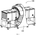
- Ein CT-Detektionsgerät (100), umfassend:ein CT-Bildgebungssystem (110), umfassend eine Strahlungsquelle, einen Detektor und einen Drehrahmen (111), wobei die Strahlungsquelle und der Detektor auf dem Drehrahmen (111) montiert sind und ein Umfang des Drehrahmens (111) mit mindestens einem ersten Loch (112) versehen ist;einen Tragständer (120), wobei der Drehrahmen (111) über ein Schleifringslager an dem Tragständer (120) befestigt ist und ein Umfang des Tragständers (120) mit mindestens einem zweiten Loch (122) versehen ist, das mit dem mindestens einen ersten Loch (112) fluchtet; undeine erste Hülse (130), lösbar in das ausgerichtete erste Loch (112) und das zweite Loch (122) eingesetzt, wobei die erste Hülse (130) einen ersten Zusammenwirkabschnitt (133) umfasst und der erste Zusammenwirkabschnitt (133) mit einem ersten Verriegelungsabschnitt (150) zusammenwirkt, um den Drehrahmen (111) während eines Austauschs des Schleifringslagers zu verriegeln;wobei die erste Hülse (130) einen ersten zylindrischen Abschnitt (131), der mit dem ersten Loch (112) in Eingriff steht, und einen zweiten zylindrischen Abschnitt (132), der mit dem zweiten Loch (122) in Eingriff steht, umfasst;wobei eine Außenfläche des ersten zylindrischen Abschnitts (131) und eine Innenfläche des ersten Lochs (112) Gewinde aufweisen und/oder eine Außenfläche des zweiten zylindrischen Abschnitts (132) und eine Innenfläche des zweiten Lochs (122) Gewinde aufweisen; undwobei der erste Zusammenwirkabschnitt (133) als Gewinde an einer Innenfläche des ersten zylindrischen Abschnitts (131) oder als Gewinde an Innenflächen des ersten zylindrischen Abschnitts (131) und des zweiten zylindrischen Abschnitts (132) ausgebildet ist.
- Das CT-Detektionsgerät nach Anspruch 1, wobei ein Durchmesser des ersten zylindrischen Abschnitts (131) kleiner ist als ein Durchmesser des zweiten zylindrischen Abschnitts (132) und der erste zylindrische Abschnitt (131) mit dem zweiten zylindrischen Abschnitt (132) durch eine Stufe (134) verbunden ist; und
wobei ein Durchmesser des ersten Lochs (112) kleiner ist als ein Durchmesser des zweiten Lochs (122). - Das CT-Detektionsgerät nach Anspruch 1, wobei der erste Verriegelungsabschnitt (150) als Schraube ausgebildet ist.
- Das CT-Detektionsgerät nach Anspruch 1, wobeidas mindestens eine erste Loch (112) eine Mehrzahl erster Löcher (112) umfasst, die gleichmäßig am Umfang des Drehrahmens (111) verteilt sind; unddas mindestens eine zweite Loch (122) eine Mehrzahl zweiter Löcher (122) umfasst, die gleichmäßig am Umfang einer Aufnahmekavität (121) des Tragständers (120) verteilt sind, und der Drehrahmen (111) in der Aufnahmekavität (121) montiert ist.
- Das CT-Detektionsgerät nach Anspruch 1, wobei eine Stirnfläche eines Endes der ersten Hülse (130) eine Positionierfläche ist.
- Das CT-Detektionsgerät nach einem der Ansprüche 1-5, ferner umfassend eine zweite Hülse (140), die lösbar in das zweite Loch (122) eingesetzt wird, falls die erste Hülse (130) aus dem ersten Loch (112) und dem zweiten Loch (122) entfernt ist, wobei die zweite Hülse (140) einen zweiten Zusammenwirkabschnitt (141) umfasst, und wobei der zweite Zusammenwirkabschnitt (141) und das erste Loch (112) mit einem zweiten Verriegelungsabschnitt (160) zusammenwirken, um den Drehrahmen (111) während einer Wartung des CT-Detektionsgeräts (100) zu verriegeln;wobei eine Außenfläche der zweiten Hülse (140) und eine Innenfläche des zweiten Lochs (122) Gewinde aufweisen;wobei der zweite Zusammenwirkabschnitt (141) als Stiftloch innerhalb der zweiten Hülse (140) ausgebildet ist, der zweite Verriegelungsabschnitt (160) als Stift ausgebildet ist und der Stift in das erste Loch (112) und das Stiftloch innerhalb der zweiten Hülse (140) eingesetzt ist; undwobei Innendurchmesser des Stiftlochs und des ersten Lochs (112) im Wesentlichen gleich einem Außendurchmesser des Stifts sind.
- Das CT-Detektionsgerät nach Anspruch 1, wobei der erste Verriegelungsabschnitt (150) als Stift ausgebildet ist und der Stift in das erste Loch (112) und den ersten Zusammenwirkabschnitt (133) eingesetzt ist, um den Drehrahmen (111) während einer Wartung des CT-Detektionsgeräts (100) zu verriegeln.
Applications Claiming Priority (2)
| Application Number | Priority Date | Filing Date | Title |
|---|---|---|---|
| CN202010473343.5A CN113740363B (zh) | 2020-05-29 | 2020-05-29 | 用于ct检测装置的锁定组件和ct检测装置 |
| PCT/CN2021/094357 WO2021238720A1 (zh) | 2020-05-29 | 2021-05-18 | 用于ct检测装置的锁定组件和ct检测装置 |
Publications (3)
| Publication Number | Publication Date |
|---|---|
| EP4159134A1 EP4159134A1 (de) | 2023-04-05 |
| EP4159134A4 EP4159134A4 (de) | 2024-07-17 |
| EP4159134B1 true EP4159134B1 (de) | 2025-07-02 |
Family
ID=78724499
Family Applications (1)
| Application Number | Title | Priority Date | Filing Date |
|---|---|---|---|
| EP21812364.4A Active EP4159134B1 (de) | 2020-05-29 | 2021-05-18 | Verriegelungsanordnung für ct-detektionsvorrichtung und ct-detektionsvorrichtung |
Country Status (4)
| Country | Link |
|---|---|
| EP (1) | EP4159134B1 (de) |
| JP (1) | JP7518211B2 (de) |
| CN (1) | CN113740363B (de) |
| WO (1) | WO2021238720A1 (de) |
Families Citing this family (3)
| Publication number | Priority date | Publication date | Assignee | Title |
|---|---|---|---|---|
| CN119949863A (zh) * | 2025-04-11 | 2025-05-09 | 安络杰医疗器械(上海)有限公司 | 一种ct扫描架及ct扫描装置 |
| CN120167987B (zh) * | 2025-04-17 | 2025-10-03 | 安络杰医疗器械(上海)有限公司 | 一种大口径ct扫描装置 |
| CN120742434B (zh) * | 2025-08-21 | 2025-12-05 | 上海物影科技有限公司 | 一种可实现螺旋ct扫描的定子系统 |
Family Cites Families (16)
| Publication number | Priority date | Publication date | Assignee | Title |
|---|---|---|---|---|
| JP4406101B2 (ja) * | 1998-10-16 | 2010-01-27 | 株式会社東芝 | X線ct装置 |
| CN201785529U (zh) * | 2010-07-12 | 2011-04-06 | 中国电子科技集团公司第二研究所 | 一种用于上下料机的料片挡板的调节机构 |
| JP2013167347A (ja) * | 2012-02-17 | 2013-08-29 | Bastem:Kk | インサートネジを用いた締結装置 |
| CN103089788B (zh) * | 2013-02-04 | 2015-09-30 | 慈溪市附海大奇电器厂 | 一种外拉式自锁螺栓 |
| CN203576528U (zh) * | 2013-09-29 | 2014-05-07 | 上海西门子医疗器械有限公司 | Ct机架部件和ct机 |
| US9492126B2 (en) * | 2014-01-27 | 2016-11-15 | Epica International, Inc. | Radiological imaging system |
| US10039505B2 (en) * | 2014-07-22 | 2018-08-07 | Samsung Electronics Co., Ltd. | Anatomical imaging system having fixed gantry and rotating disc, with adjustable angle of tilt and increased structural integrity, and with improved power transmission and position sensing |
| JP6382673B2 (ja) * | 2014-10-06 | 2018-08-29 | ナックス株式会社 | 留め具 |
| WO2016199530A1 (ja) * | 2015-06-09 | 2016-12-15 | 株式会社日立製作所 | X線ct装置及びそのベアリング交換方法 |
| DE102016204006B4 (de) * | 2016-03-11 | 2025-06-18 | Siemens Healthineers Ag | Anordnung mit einem stationären Teil und einem ersten rotierenden Teil einer Gantry eines Computertomographiegeräts und Verfahren zur Wartung einer Komponente einer Gantry eines Computertomographiegeräts |
| CN105626658A (zh) * | 2016-03-26 | 2016-06-01 | 华为技术有限公司 | 一种自锁防松紧固件、紧固装置及紧固结构 |
| KR20180077989A (ko) * | 2016-12-29 | 2018-07-09 | 삼성전자주식회사 | 의료기기 |
| WO2018190867A1 (en) * | 2017-04-14 | 2018-10-18 | Analogic Corporation | Wheel and lift unit for radiation imaging modalities |
| CN107714064B (zh) * | 2017-09-28 | 2021-12-31 | 北京东软医疗设备有限公司 | 成像装置及医疗设备 |
| CN208931962U (zh) * | 2018-09-20 | 2019-06-04 | 明峰医疗系统股份有限公司 | 一种ct转子锁定支撑结构 |
| US10881362B2 (en) * | 2018-11-20 | 2021-01-05 | General Electric Company | Systems for laser alignment |
-
2020
- 2020-05-29 CN CN202010473343.5A patent/CN113740363B/zh active Active
-
2021
- 2021-05-18 EP EP21812364.4A patent/EP4159134B1/de active Active
- 2021-05-18 JP JP2022573617A patent/JP7518211B2/ja active Active
- 2021-05-18 WO PCT/CN2021/094357 patent/WO2021238720A1/zh not_active Ceased
Also Published As
| Publication number | Publication date |
|---|---|
| EP4159134A1 (de) | 2023-04-05 |
| EP4159134A4 (de) | 2024-07-17 |
| CN113740363B (zh) | 2022-08-26 |
| WO2021238720A1 (zh) | 2021-12-02 |
| CN113740363A (zh) | 2021-12-03 |
| JP2023527241A (ja) | 2023-06-27 |
| JP7518211B2 (ja) | 2024-07-17 |
Similar Documents
| Publication | Publication Date | Title |
|---|---|---|
| EP4159134B1 (de) | Verriegelungsanordnung für ct-detektionsvorrichtung und ct-detektionsvorrichtung | |
| US8120198B2 (en) | Wind power turbine | |
| US10722197B2 (en) | Arrangement with a stationary part and a first rotating part of a gantry of a computed tomography scanner and method for maintaining a component of a gantry of a computed tomography scanner | |
| JP2024021330A (ja) | 回転子ロック機構および回転電機 | |
| US10786213B2 (en) | CT machine and rotator thereof | |
| JP5485722B2 (ja) | X線ct装置 | |
| CN105960205B (zh) | 具有辅助安全机构的台架 | |
| HK40087340A (en) | Locking assembly for ct detection device, and ct detection device | |
| HK40087340B (en) | Locking assembly for ct detection device, and ct detection device | |
| CN111185876B (zh) | 一种空间站在轨维修工具 | |
| CN111113007A (zh) | 单轴拧紧机 | |
| JP2011125998A (ja) | ねじ切り装置およびねじ切りリングを取り付けるための工具 | |
| US6074165A (en) | Vacuum pump with magnetic bearing system and back-up bearings | |
| US2876363A (en) | Radiation projector and charge handling means therefor | |
| EP4234966B1 (de) | Tragrahmen für ct-gleitringlager | |
| JP6368774B2 (ja) | アイソセンタとの画像化システム回転構成部品の整列 | |
| JPH1071531A (ja) | ボルトの遠隔ロック工具 | |
| CN218922611U (zh) | 医学影像系统的转盘、ct机的机架、ct机和医学影像系统 | |
| CN106333704A (zh) | Pet机架 | |
| CN212434821U (zh) | 天线旋转安装机构 | |
| CN222765180U (zh) | 用于ct机的眼形框组件、机架、ct机和pet/ct机 | |
| US20140301526A1 (en) | Computerized tomography (ct) imaging system with improved x-ray tube mount | |
| CN106976169B (zh) | 一种多线切割机主轴防转机构 | |
| US2469993A (en) | Locking device | |
| CN218684433U (zh) | 医疗成像设备 |
Legal Events
| Date | Code | Title | Description |
|---|---|---|---|
| STAA | Information on the status of an ep patent application or granted ep patent |
Free format text: STATUS: THE INTERNATIONAL PUBLICATION HAS BEEN MADE |
|
| PUAI | Public reference made under article 153(3) epc to a published international application that has entered the european phase |
Free format text: ORIGINAL CODE: 0009012 |
|
| STAA | Information on the status of an ep patent application or granted ep patent |
Free format text: STATUS: REQUEST FOR EXAMINATION WAS MADE |
|
| 17P | Request for examination filed |
Effective date: 20221219 |
|
| AK | Designated contracting states |
Kind code of ref document: A1 Designated state(s): AL AT BE BG CH CY CZ DE DK EE ES FI FR GB GR HR HU IE IS IT LI LT LU LV MC MK MT NL NO PL PT RO RS SE SI SK SM TR |
|
| DAV | Request for validation of the european patent (deleted) | ||
| DAX | Request for extension of the european patent (deleted) | ||
| REG | Reference to a national code |
Ref country code: HK Ref legal event code: DE Ref document number: 40087340 Country of ref document: HK |
|
| A4 | Supplementary search report drawn up and despatched |
Effective date: 20240613 |
|
| RIC1 | Information provided on ipc code assigned before grant |
Ipc: G01N 23/046 20180101ALI20240610BHEP Ipc: A61B 6/03 20060101AFI20240610BHEP |
|
| GRAP | Despatch of communication of intention to grant a patent |
Free format text: ORIGINAL CODE: EPIDOSNIGR1 |
|
| STAA | Information on the status of an ep patent application or granted ep patent |
Free format text: STATUS: GRANT OF PATENT IS INTENDED |
|
| RIC1 | Information provided on ipc code assigned before grant |
Ipc: G01N 23/046 20180101ALI20241219BHEP Ipc: A61B 6/03 20060101AFI20241219BHEP |
|
| INTG | Intention to grant announced |
Effective date: 20250122 |
|
| GRAS | Grant fee paid |
Free format text: ORIGINAL CODE: EPIDOSNIGR3 |
|
| GRAA | (expected) grant |
Free format text: ORIGINAL CODE: 0009210 |
|
| STAA | Information on the status of an ep patent application or granted ep patent |
Free format text: STATUS: THE PATENT HAS BEEN GRANTED |
|
| AK | Designated contracting states |
Kind code of ref document: B1 Designated state(s): AL AT BE BG CH CY CZ DE DK EE ES FI FR GB GR HR HU IE IS IT LI LT LU LV MC MK MT NL NO PL PT RO RS SE SI SK SM TR |
|
| REG | Reference to a national code |
Ref country code: GB Ref legal event code: FG4D |
|
| REG | Reference to a national code |
Ref country code: CH Ref legal event code: EP |
|
| REG | Reference to a national code |
Ref country code: DE Ref legal event code: R096 Ref document number: 602021033492 Country of ref document: DE |
|
| REG | Reference to a national code |
Ref country code: IE Ref legal event code: FG4D |
|
| REG | Reference to a national code |
Ref country code: NL Ref legal event code: MP Effective date: 20250702 |
|
| PG25 | Lapsed in a contracting state [announced via postgrant information from national office to epo] |
Ref country code: PT Free format text: LAPSE BECAUSE OF FAILURE TO SUBMIT A TRANSLATION OF THE DESCRIPTION OR TO PAY THE FEE WITHIN THE PRESCRIBED TIME-LIMIT Effective date: 20251103 |
|
| PG25 | Lapsed in a contracting state [announced via postgrant information from national office to epo] |
Ref country code: NL Free format text: LAPSE BECAUSE OF FAILURE TO SUBMIT A TRANSLATION OF THE DESCRIPTION OR TO PAY THE FEE WITHIN THE PRESCRIBED TIME-LIMIT Effective date: 20250702 |
|
| REG | Reference to a national code |
Ref country code: AT Ref legal event code: MK05 Ref document number: 1808318 Country of ref document: AT Kind code of ref document: T Effective date: 20250702 |
|
| PG25 | Lapsed in a contracting state [announced via postgrant information from national office to epo] |
Ref country code: IS Free format text: LAPSE BECAUSE OF FAILURE TO SUBMIT A TRANSLATION OF THE DESCRIPTION OR TO PAY THE FEE WITHIN THE PRESCRIBED TIME-LIMIT Effective date: 20251102 |
|
| PG25 | Lapsed in a contracting state [announced via postgrant information from national office to epo] |
Ref country code: NO Free format text: LAPSE BECAUSE OF FAILURE TO SUBMIT A TRANSLATION OF THE DESCRIPTION OR TO PAY THE FEE WITHIN THE PRESCRIBED TIME-LIMIT Effective date: 20251002 |
|
| REG | Reference to a national code |
Ref country code: LT Ref legal event code: MG9D |
|
| PG25 | Lapsed in a contracting state [announced via postgrant information from national office to epo] |
Ref country code: AT Free format text: LAPSE BECAUSE OF FAILURE TO SUBMIT A TRANSLATION OF THE DESCRIPTION OR TO PAY THE FEE WITHIN THE PRESCRIBED TIME-LIMIT Effective date: 20250702 |
|
| PG25 | Lapsed in a contracting state [announced via postgrant information from national office to epo] |
Ref country code: FI Free format text: LAPSE BECAUSE OF FAILURE TO SUBMIT A TRANSLATION OF THE DESCRIPTION OR TO PAY THE FEE WITHIN THE PRESCRIBED TIME-LIMIT Effective date: 20250702 |
|
| PG25 | Lapsed in a contracting state [announced via postgrant information from national office to epo] |
Ref country code: HR Free format text: LAPSE BECAUSE OF FAILURE TO SUBMIT A TRANSLATION OF THE DESCRIPTION OR TO PAY THE FEE WITHIN THE PRESCRIBED TIME-LIMIT Effective date: 20250702 |
|
| PG25 | Lapsed in a contracting state [announced via postgrant information from national office to epo] |
Ref country code: GR Free format text: LAPSE BECAUSE OF FAILURE TO SUBMIT A TRANSLATION OF THE DESCRIPTION OR TO PAY THE FEE WITHIN THE PRESCRIBED TIME-LIMIT Effective date: 20251003 |
|
| PG25 | Lapsed in a contracting state [announced via postgrant information from national office to epo] |
Ref country code: CZ Free format text: LAPSE BECAUSE OF FAILURE TO SUBMIT A TRANSLATION OF THE DESCRIPTION OR TO PAY THE FEE WITHIN THE PRESCRIBED TIME-LIMIT Effective date: 20250702 Ref country code: SE Free format text: LAPSE BECAUSE OF FAILURE TO SUBMIT A TRANSLATION OF THE DESCRIPTION OR TO PAY THE FEE WITHIN THE PRESCRIBED TIME-LIMIT Effective date: 20250702 |
|
| PG25 | Lapsed in a contracting state [announced via postgrant information from national office to epo] |
Ref country code: LV Free format text: LAPSE BECAUSE OF FAILURE TO SUBMIT A TRANSLATION OF THE DESCRIPTION OR TO PAY THE FEE WITHIN THE PRESCRIBED TIME-LIMIT Effective date: 20250702 |
|
| PG25 | Lapsed in a contracting state [announced via postgrant information from national office to epo] |
Ref country code: BG Free format text: LAPSE BECAUSE OF FAILURE TO SUBMIT A TRANSLATION OF THE DESCRIPTION OR TO PAY THE FEE WITHIN THE PRESCRIBED TIME-LIMIT Effective date: 20250702 Ref country code: PL Free format text: LAPSE BECAUSE OF FAILURE TO SUBMIT A TRANSLATION OF THE DESCRIPTION OR TO PAY THE FEE WITHIN THE PRESCRIBED TIME-LIMIT Effective date: 20250702 |
|
| PG25 | Lapsed in a contracting state [announced via postgrant information from national office to epo] |
Ref country code: RS Free format text: LAPSE BECAUSE OF FAILURE TO SUBMIT A TRANSLATION OF THE DESCRIPTION OR TO PAY THE FEE WITHIN THE PRESCRIBED TIME-LIMIT Effective date: 20251002 |
|
| PG25 | Lapsed in a contracting state [announced via postgrant information from national office to epo] |
Ref country code: ES Free format text: LAPSE BECAUSE OF FAILURE TO SUBMIT A TRANSLATION OF THE DESCRIPTION OR TO PAY THE FEE WITHIN THE PRESCRIBED TIME-LIMIT Effective date: 20250702 |