EP4157720B1 - Modularer kanalmontierter möbelaufsatz - Google Patents
Modularer kanalmontierter möbelaufsatz Download PDFInfo
- Publication number
- EP4157720B1 EP4157720B1 EP20760628.6A EP20760628A EP4157720B1 EP 4157720 B1 EP4157720 B1 EP 4157720B1 EP 20760628 A EP20760628 A EP 20760628A EP 4157720 B1 EP4157720 B1 EP 4157720B1
- Authority
- EP
- European Patent Office
- Prior art keywords
- structural member
- floor
- furnishing
- passenger
- attachment elements
- Prior art date
- Legal status (The legal status is an assumption and is not a legal conclusion. Google has not performed a legal analysis and makes no representation as to the accuracy of the status listed.)
- Active
Links
Images


Classifications
-
- B—PERFORMING OPERATIONS; TRANSPORTING
- B64—AIRCRAFT; AVIATION; COSMONAUTICS
- B64D—EQUIPMENT FOR FITTING IN OR TO AIRCRAFT; FLIGHT SUITS; PARACHUTES; ARRANGEMENT OR MOUNTING OF POWER PLANTS OR PROPULSION TRANSMISSIONS IN AIRCRAFT
- B64D11/00—Passenger or crew accommodation; Flight-deck installations not otherwise provided for
- B64D11/06—Arrangements of seats, or adaptations or details specially adapted for aircraft seats
- B64D11/0648—Lower frame constructions
-
- B—PERFORMING OPERATIONS; TRANSPORTING
- B64—AIRCRAFT; AVIATION; COSMONAUTICS
- B64D—EQUIPMENT FOR FITTING IN OR TO AIRCRAFT; FLIGHT SUITS; PARACHUTES; ARRANGEMENT OR MOUNTING OF POWER PLANTS OR PROPULSION TRANSMISSIONS IN AIRCRAFT
- B64D11/00—Passenger or crew accommodation; Flight-deck installations not otherwise provided for
- B64D11/06—Arrangements of seats, or adaptations or details specially adapted for aircraft seats
- B64D11/0639—Arrangements of seats, or adaptations or details specially adapted for aircraft seats with features for adjustment or converting of seats
-
- B—PERFORMING OPERATIONS; TRANSPORTING
- B64—AIRCRAFT; AVIATION; COSMONAUTICS
- B64D—EQUIPMENT FOR FITTING IN OR TO AIRCRAFT; FLIGHT SUITS; PARACHUTES; ARRANGEMENT OR MOUNTING OF POWER PLANTS OR PROPULSION TRANSMISSIONS IN AIRCRAFT
- B64D11/00—Passenger or crew accommodation; Flight-deck installations not otherwise provided for
- B64D11/06—Arrangements of seats, or adaptations or details specially adapted for aircraft seats
- B64D11/0696—Means for fastening seats to floors, e.g. to floor rails
Definitions
- the field of the invention relates to attachment mechanisms for passenger compartment furnishings.
- WO-2013/144935 A2 describes a base frame assembly for installing a passenger seat in an aircraft, which has main frame including seat and lateral support structures with one and two seat fittings, respectively, and a secondary frame coupled to the main frame and including a seat fitting.
- passenger safety and comfort are facilitated by providing structurally sound passenger furnishings, including seating arrangements and a wide variety of amenities.
- Structures can be provided within the passenger cabin that are directed to providing secure seating, supporting safety features, providing storage for flotation devices or oxygen, for providing convenient small-article storage, or for supporting media devices, both built-in and passenger-provided.
- air transport must cope with higher speeds and more limited space and weight constraints, and passenger aircraft may be in service through multiple iterations of improvements in passenger seat and amenity designs. Therefore, not only must aircraft furnishings be lightweight, safe, and secure; they should also be adaptable to multiple layouts and be movable without incurring excess costs or requiring significant layout changes in any given passenger cabin. To that end, improvements in the underlying structures that support passenger amenities are desired.
- a crossbeam assembly for mounting a passenger compartment furnishing is defined in appended claim 1.
- a passenger compartment furnishing is defined in appaended claim 6.
- a method for installing a passenger compartment furnishing is defined in appended claim 12.
- the described embodiments of the invention provide modular assembly for connecting a passenger furnishing to a cabin floors for installing passenger furnishings, passenger seats, and other fixed amenities to a channels in an aircraft cabin floor. While the modular assembly for connecting a passenger furnishing to a cabin floors are discussed for use with aircraft passenger furnishings, they are by no means so limited. Rather, embodiments of the modular assembly for connecting a passenger furnishing to a cabin floors may be used with a wide variety of channel-mounted amenities of any type or otherwise as desired, and in a variety of passenger cabin arrangements for alternative conveyances.
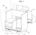
- an arrangement of passenger furnishings 100 includes at least one, often multiple, passenger furnishing assemblies 105 that are connected to the passenger cabin by an arrangement of floor-mounted channels 103.
- the floor-mounted channels 103 can be open U-channel channels or comparable, can be closed channels with periodically spaced mounting features or holes for receiving attachments, or can be any other suitable form of channel.
- Floor-mounted channels 103 are a common form of floor-mounted structural support in the aircraft industry, however, the exact spacing and the type of channel vary significantly between different airframes and between the customized floorplans prepared for different airlines.
- Existing passenger furnishings are designed based on known floorplans in order to attach directly to the passenger cabin floor or to preassembled attachment means that are positioned with fixed, predetermined spacing. As a result, existing passenger furnishings are not readily replaceable and are not necessarily standardized between different airframes or cabin designs.
- passenger furnishing assemblies 105 include modular attachment mechanisms 107 that include a first structural member 109 (e.g., a crossbeam) that can be positioned intersecting the floor-mounted channels 103 and mounted to the floor-mounted channels via attachment elements 111 (e.g., brackets) connected to the floor-mounted channels by floor connectors 113.
- the structural members 109 include mounting elements 115 that connect the structural members with the body 117 of each passenger furnishing assembly 105.
- attachment elements 111 are movable along a length of each structural member 109, allowing the attachment elements 111 to be positioned at any suitable spacing with respect to each other along the structural member, and then allowing the structural member 109 to be placed at any suitable offset with respect to the floor-mounted channels 103 to which the attachment elements are mounted.
- the passenger furnishing assemblies 105 may be formed of materials including but not limited to aluminum, stainless steel, aramid fibers, polycarbonate, polypropylene, other metallic materials, composite materials, or other similar materials, or any suitable combination of the above materials.
- the particular passenger furnishing assemblies 105 illustrated herein are shown as examples only, and the modular attachment mechanisms 107 are compatible with a wide variety of passenger furnishings, including but not limited to: simple passenger seat shrouds; complex passenger seat enclosures that can include multimedia entertainment systems, tray tables, or similar amenities; multi-use stations such as galley furnishings; passenger seating arrangements; or any other suitable fixture that can be secured to an aircraft cabin by way of floor-mounted channels or tracks.
- the strength of the modular attachment mechanisms 107 can be selected based on the physical dimensions and weight of the passenger furnishing assembly, but is generally configured to support the passenger furnishing assembly against a potential forward load of 9 g acceleration, and a downward load of at least 8.8 g acceleration.
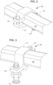
- FIG. 2 is a perspective view of a first example connecting mechanism 200 for the arrangement of passenger furnishings of FIG. 1 , in accordance with various embodiments.
- the connecting mechanism 200 includes an attachment element 111 shaped to receive the structural member 109.
- the structural member 109 can be adapted to many cross-sectional shapes, including (as shown) a rounded square configuration, but also including round, elliptical, rectangular, triangular, flat or channeled (e.g. shaped like a C-beam, L-beam, T-beam, or I-beam) or other suitable cross-sections, including both rounded and angular designs.
- the structural member 109 is an extruded component having a consistent cross-sectional shape along its length.
- a cross section that prevents rotation with respect to attachment elements 111 may be preferred.
- cross sections that allow rotation with respect to the attachment elements 111 can be permitted, and may be advantageous for providing enhanced strength relative to weight.
- the attachment element 111 includes, on one side, a securing bolt 119 that can be tightened to rigidly connect the attachment element to the structural member 109 at any suitable position along the structural member. When loosened, the securing bolt 119 can permit the attachment element 111 to open sufficient to allow adjustment of the structural member, e.g., for adjusting the position of a passenger furnishing (105, FIG. 1 ) from side to side, or for adjusting the spacing of multiple attachment elements along the same structural member.
- the attachment element 111 further includes a footing 123 that is attached to a floor connector 113, and is shown in further detail in FIG. 3 .
- FIG. 3 is a second perspective view of the example connecting mechanism shown in FIG. 2 , in accordance with various embodiments, illustrating floor connector 113 in further detail.
- the floor connector 113 can be any suitable bolt or screw assembly that is sized to attach to the floor-mounted channels 103 described above with reference to FIG. 1 .
- the floor connector 113 can be a flanged bolt that connects with a hole or channel in the floor-mounted channels 103 and is attached at a predefined spacing to the footing 129 of the attachment element 111 by way of one or more nuts.
- the floor connector 113 can be any other suitable bolt, a screw that connects into one of the floor-mounted channels 103, a rivet, or an adhesive connector.
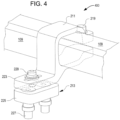
- FIG. 4 is a perspective view of a second example connecting mechanism 400 for the arrangement of passenger furnishings shown in FIG. 1 , in accordance with various embodiments.
- the connecting mechanism 400 includes an attachment element 211 shaped to attach to one of the modular structural members 109 in a similar manner to attachment element 111 ( FIGS. 1-3 ).
- the attachment element 211 can be tightened to fixedly attach to the structural member 109 via, e.g., a securing bolt 219.
- the securing bolt 219 can permit the attachment element 211 to open sufficient to allow adjustment of the structural member, e.g., for adjusting the position of a passenger furnishing (105, FIG. 1 ) from side to side, or for adjusting the spacing of multiple attachment elements along the same structural member.
- the attachment element 211 further includes a footing 223 that is attached to a floor connector assembly 213.
- the floor connector assembly 213 includes an attachment block 225 that is shaped to interface with a floor-mounted channel (e.g., channel 103, FIG. 1 ) and secured to each other and in place by expansion bolts 227.
- the footing 223 of the attachment element 211 can be mounted to the floor connector assembly 213 by any suitable connector 229, e.g., bolts, screws, rivets, adhesive or chemical fasteners, or the like.
- the floor-mounted channels 103 can include individual bores that the bolts 227 pass through in order to secure the floor connector assembly 213 in position.
- the floor-mounted channels can include a channel in which bolts 227 attach and expand when tightened to fix the floor connector assemblies 213 in position along the floor-mounted channels.
- the floor-mounted channels can include a hybrid construction of a continuous channel with discrete features (e.g., an open track with discrete cutouts) sized to receive the floor connector assemblies 213 at discrete locations or at locations along the continuous channel.
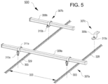
- FIG. 5 is a perspective view of a first example of a modular assembly 500500 for passenger furnishings like those shown in FIG. 1 , in accordance with various embodiments.
- the modular assembly 500 is configured to attach to a series of floor-mounted channels 303, shown here with an open track with a series of connected mounting openings 329. It will be understood that any of the embodiments described above suitable for use with floor-mounted channels 103 ( FIGS. 1-4 ) can be used in conjunction with floor-mounted channels 303, and vice versa.
- the modular assembly 500 includes at least a first connecting assembly 307a that includes one structural member 309a that is sized to pass across at least two parallel floor-mounted channels 303, and which can include further attachment elements (not shown) for supporting any suitable passenger cabin fixture.
- This first structural member 309a has attached two attachment elements 311a, which can be configured similar to attachment elements 111 ( FIGS. 1-3 ), 211 ( FIG. 4 ), or can be functionally comparable.
- the attachment elements 311 attached to the first structural member 309a can be connected to each of the two parallel floor-mounted channels 303 via floor connector assemblies 313a-c, thereby securing the first structural member 309a relative to the floor of the passenger cabin.
- the exact spacing of the attachment elements 311a connected to the first structural member 309a can be varied in order to accommodate the spacing 333 of the floor-mounted channels 303, which vary between airframes and individual cabin layouts.
- the spacing 333 can be between adjacent floor-mounted channels 303, or between floor-mounted channels in different aisle regions of the airframe (e.g., bridging from closely-spaced channels near the sides vs. near the center of an airframe).
- Attachment elements 311a can be spaced as close as about 2.5 cm from each other, and may be used at that distance in order to mount passenger furnishings to closely spaced floor-mounted channels 303.
- Attachment elements 311a may be spaced according to standard channel spacing of common carriers, e.g., about 55 cm or 22.04". Alternatively, attachment elements 311a can be spaced father apart in order to support larger passenger furnishings, or to support passenger furnishings across more widely spaced floor-mounted channels. For example, attachment elements 311a may be spaced as far apart as the entire width of the central floor-mounted channels (which can be, for some airframes, approximately 135 cm, or 66"), across multiple channels or sets of channels, or may be spaced closer together for installation on smaller regional aircraft. According to some embodiments, the attachment elements 311a can be spaced father apart than the spacing of adjacent floor-mounted channels 303 in order to accommodate mounting the structural member 309a at an angle (non-perpendicular) to the floor-mounted channels.
- passenger furnishings can be attached to the floor of a passenger cabin using one or multiple floor-mounted channels 303 in conjunction with one crossbar 309a or via multiple crossbars having similar dimensions and attached in the same way forward or aft of the crossbar.
- passenger furnishings can be attached to the floor of the passenger cabin using at least one long crossbar 309a that spans two or more of the floor-mounted channels 303, in conjunction with additional and more limited attachment means including, but not limited to, additional crossbars having shorter or longer dimensions, or by direct attachment mechanisms that do not involve crossbars. For example, as shown in FIG.
- a modular assembly 500 can include a more limited, second connecting assembly 307b that includes a second, shorter structural member 309b that can cross fewer floor-mounted channels 303 than the first, long structural member 309a.
- the second structural member 309b is shown crossing a singular floor-mounted channel 303 and positioned aft of the first, long structural member 309a.
- the second structural member 309b is attached to the singular floor-mounted channel 303 via an attachment element 311b and attached floor connector assembly 313b.
- first structural member 309a long crossbars
- second structural member 309b short crossbars
- the modular assembly 500 can also include standalone connecting assemblies 307c that include standalone attachments 309c that can be mounted to one of the floor-mounted channels 303 and attached directly to the passenger furnishings without intervening crossbars.
- Floor connector assembles 313b and 313c can resemble the floor connector assemblies 313a described above, or can be configured differently.
- floor connector assembles 313b and 313c are shaped to mate with one or more of the openings 329 along the conduits 303 so that these floor connector assemblies can be fixed at discrete locations along the conduits, whereas floor connector assemblies 313a can be configured with an expansion bolt or similar connector that permits an installer to slide the first structural member 309a forward or aft along the conduits 303 before tightening the floor connector assemblies to fix the first structural member in place.
- the floor connector assemblies 313 can slidingly mate with the two floor-mounted channels in an unsecured configuration that allows for fine adjustment and placement, and to rigidly mate with the two floor-mounted channels when transitioned to a secured configuration (e.g., tightened or expanded).
- the floor connector assemblies 313 can mate with the channel 303 at discrete positions (e.g., mounting holes, openings, or the like) and can be secured in position once placed at the desired position.
- modular assemblies for installing passenger furnishings into passenger compartments can include floor-mounted channels with regularly spaced holes (e.g., continuous channels 303 with openings 329, FIG. 5 ), or floor-mounted channels that include other attachment means, such as channels with a continuous open track, rails with discrete mounting holes, or other suitable fastening means.
- FIG. 6 is a perspective view of a second example of a modular assembly 600 for installing passenger furnishings like those shown in FIG. 1 , in accordance with various embodiments.
- the modular assembly 600 includes one or multiple connecting assemblies 407 that each include one structural member 409 that is sized to pass across at least two parallel floor-mounted channels 403, or optionally any suitable number of parallel floor-mounted channels.
- Each structural member 409 can include further attachment elements (not shown) that attach to the structural member for supporting any suitable passenger cabin fixture such as, but not limited to, passenger furnishing 105 ( FIG. 1 ).
- Each one of the structural members 409 is supported by and attached to a series of attachment elements 411, which can be configured similar to attachment elements 111 ( FIGS. 1-3 ), 211 ( FIG. 4 ), 311a-c ( FIG. 5 ) or can be functionally comparable.
- the attachment elements 411 attached to each structural member 409 can connect the structural members to any suitable number of the parallel floor-mounted channels 403 via floor connector assemblies 413, thereby securing the structural members to the floor of the passenger cabin.
- attachment elements 411 connected to each structural member can be varied in order to accommodate the spacing 433, 435 between adjacent floor-mounted channels 403, which can vary across the width of the cabin, between different airframes, and between cabin layouts even in the same airframe.
- Attachment elements 411 can be spaced as close as about 2.5 cm from each other, and may be used at that distance in order to mount passenger furnishings to closely spaced floor-mounted channels 403.
- Attachment elements 411 may be spaced according to standard channel spacing of common carriers, e.g., about 55 cm or 22.04" (for the A350).
- attachment elements 411 can be spaced father apart in order to support larger passenger furnishings, or to support passenger furnishings across more widely spaced floor-mounted channels.
- attachment elements 411 may be spaced as far apart as the entire width of the central floor-mounted channels (which is approximately 135 cm, or 66", on the A350), across multiple channels or sets of channels, or may be spaced closer together for installation on smaller regional aircraft.
- the attachment elements 411 can be spaced father apart than the spacing of adjacent floor-mounted channels 403 in order to accommodate mounting the structural member 409 at an angle (non-perpendicular) to the floor-mounted channels.
- the modular assembly 600 utilizes floor connector assemblies 413 similar to floor connector assemblies 213 shown in FIG. 4 , in which each floor connector assembly 413 includes an attachment block 425 shaped to interface with a floor-mounted channel 403, secured in place along the respective channel to which the floor connector assembly is attached by expansion bolts 427 and connected to the attachment elements 411 by a connector 429.
- floor connector assemblies 413 can be replaced other suitable connector assemblies described above, e.g., floor connector assemblies 113 ( FIG. 1 ), 213 ( FIG. 4 ), 313 ( FIG. 5 ), or other suitable connector assemblies.
- Floor connector assemblies 413 are shown connected to channels 403 that have discrete mounting holes 429, but can be installed via similar connectors to channels that have a continuous lengthwise track, or to channels having a modified track with periodic openings (e.g., channels 303 and openings 329, FIG. 5 ).
- the floor connector assemblies 413 can slidingly mate with the two floor-mounted channels in an unsecured configuration that allows for fine adjustment and placement, and to rigidly mate with the two floor-mounted channels when transitioned to a secured configuration (e.g. tightened or expanded).
- the floor connector assemblies 413 can mate with the channel 403 at discrete positions (e.g., mounting holes, openings, or the like) and can be secured in position once placed at the desired position.
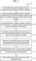
- FIG. 7 is a process flow diagram illustrating an example process 700 for installing a passenger furnishing using a modular assembly for connecting a passenger furnishing to a cabin floor, according to various embodiments.
- attachment elements e.g., brackets for receiving the crossbars and having floor attachment elements
- the brackets can be installed along a crossbeam for connecting with channels in a passenger cabin floor.
- the brackets can be attached at a distance from one another that matches the separation between channels in the cabin floor, however, the exact spacing may be adjusted upon installation as, generally, the brackets are movable along the crossbeam (or the crossbeam is movable when loosely installed in the brackets).
- floor attachment elements of the brackets attached to the crossbeam can be inserted into the channels in the passenger cabin floor and fixed in place along the channels.
- affixing the floor attachment elements to the channels includes inserting a connector of each floor attachment element into a slot or hole among a series of spaced apart slots or holes along a length of each channel. See, e.g., FIG. 5 .
- affixing the floor attachment elements to the channels includes clamping each floor attachment element to a continuous slot or opening in one of the channels. See, e.g., FIG. 6 .
- Suitable force to rigidly affix the floor attachment elements can be achieved using a bolt, screw, or other suitable clamping member or assembly such as, but not limited to, a block and bolt assembly such as floor connector assembly 213 ( FIG. 4 ).
- any suitable number of additional crossbeams can be attached to the channels at predetermined distances forward or aft of the first crossbeam via additional sets of brackets, according to any of the specific methods described above.
- additional standalone attachment elements can be attached to the channels forward or aft of any one of the crossbeams and aligned for supporting specific elements of a passenger furnishing that are not compatible with a crossbeam. See, e.g. standalone connecting assemblies 307c in FIG. 5 , or similar.
- the brackets and/or standalone attachment elements can be adjusted in position forward or aft after installation to align with a required final location suitable for supporting the passenger furnishing before the floor attachment elements thereof are tightened to rigidly fix the modular assembly for connecting a passenger furnishing to a cabin floor to the cabin floor.
- crossbeams attached to the brackets can be adjusted in a direction orthogonal to the channels in the cabin floor to align with the required final location suitable for supporting the passenger furnishing before the brackets are tightened to rigidly connect the crossbeams with the cabin floor.
- a passenger furnishing that includes prefabricated components configured to mate with the crossbeams and/or additional standalone attachment elements can be installed to the modular assembly for connecting a passenger furnishing to a cabin floor.
- FIG. 8 is a process flow diagram illustrating a second example process 800 for installing a passenger furnishing using a modular assembly for connecting a passenger furnishing to a cabin floor, according to various embodiments in which the passenger furnishing and modular assembly for connecting a passenger furnishing to a cabin floor are connected to channels in a cabin floor as a combined assembly.
- a modular assembly for connecting a passenger furnishing to a cabin floor can be assembled with a passenger furnishing, including attaching at least one crossbar to the passenger furnishing, and optionally attaching additional crossbars and or additional standalone attachment elements to the passenger furnishing.
- attachment elements e.g., brackets for receiving the crossbars and having floor attachment elements
- the combined assembly of the passenger furnishing, crossbar(s) and brackets can then be positioned such that floor attachment elements of the brackets mate with the channels in the cabin floor.
- the crossbar(s) can be adjusted laterally before the brackets are tightened to secure the crossbar(s).
- the entire combined assembly can be adjusted forward or aft along the channels before the assembly is tightened to the cabin floor.
Landscapes
- Engineering & Computer Science (AREA)
- Aviation & Aerospace Engineering (AREA)
- Body Structure For Vehicles (AREA)
Claims (15)
- Querträgeranordnung zum Montieren einer Passagierkabineneinrichtung, wobei die Anordnung umfasst:ein erstes Strukturelement (109, 309, 409), das konfiguriert ist, um zwei bodenmontierte Kanäle (103, 303, 403) in einer Passagierkabine zu überspannen;erste und zweite Befestigungselemente (111,211,311,411), die verschiebbar mit dem ersten Strukturelement verbunden sind, und entlang des ersten Strukturelements repositionierbar sind, um an den beiden bodenmontierten Kanälen befestigt zu werden; undeine oder mehrere Einrichtungsbefestigungsmerkmale (115), die mit dem ersten Strukturelement verbunden, und positioniert sind, um die Passagierkabineneinrichtung aufzunehmen;dadurch gekennzeichnet, dass jedes der ersten und zweiten Befestigungselemente auf einer ersten Seite in Bezug zum ersten Strukturelement einen Sicherungsbolzen (119, 219), und auf einer zweiten Seite, die der ersten Seite in Bezug zum ersten Strukturelement gegenüberliegt, einen Standfuß (123) umfasst,wobei der Sicherungsbolzen (119, 219) lösbar ist, um es dem jeweiligen Befestigungselements zu ermöglichen, sich ausreichend zu öffnen, um eine Anpassung des Abstands des ersten und zweiten Befestigungselements entlang des ersten Strukturelements zu ermöglichen, und festziehbar ist, um das jeweilige Befestigungselement starr in Position entlang des ersten Strukturelements zu verbinden, wobei der Standfuß (123) an einem Bodenverbinder (113) befestigt ist, wobei jedes der ersten und zweiten Befestigungselemente (111, 211, 311, 411) geformt ist, um das erste Strukturelement (109) aufzunehmen.
- Querträgeranordnung nach Anspruch 1, wobei das erste und das zweite Befestigungselement konfiguriert sind, um sich in einer ungesicherten Konfiguration gleitend mit den beiden bodenmontierten Kanälen zusammenzufügen, und sich beim Übergang in eine gesicherte Konfiguration starr mit den beiden bodenmontierten Kanälen zusammenzufügen.
- Querträgeranordnung nach einem von Anspruch 1 bis Anspruch 2, weiter umfassend:
ein zusätzliches Befestigungselement (411), das gleitend mit dem ersten Strukturelement verbunden ist und konfiguriert ist, um an einem dritten bodenmontierten Kanal (403) befestigt zu werden. - Querträgeranordnung nach einem von Anspruch 1 bis Anspruch 2, wobei das erste und zweite Befestigungselement verriegelbar sind, um eine Bewegung des ersten Strukturelements zu verhindern, wenn das erste Strukturelement durch die Befestigungselemente an den bodenmontierten Kanälen befestigt ist.
- Querträgeranordnung nach einem von Anspruch 1 bis Anspruch 2, wobei das erste Strukturelement einen extrudierten Träger umfasst, der einen von einem ovalen, quadratischen, rechteckigen, abgerundeten quadratischen oder abgerundeten rechteckigen Querschnitt umfasst und/oder eine von einer Aluminiumlegierung, Stahllegierung, Titanlegierung, einen Polymerverbundstoff oder eine Magnesiumlegierung umfasst.
- Passagierkabineneinrichtung, umfassend:eine Querträgeranordnung nach Anspruch 1; undeinen Einrichtungskörper (117), der an dem ersten Strukturelement montiert ist, wobei der Einrichtungskörper eine oder mehrere Platten umfasst, die konfiguriert sind, um einen Abschnitt eines Passagiersitzes zu ergänzen oder zu umschreiben.
- Einrichtung nach Anspruch 6, wobei das erste Strukturelement konfiguriert ist, um zwei bodenmontierte Kanäle einer Passagierflugzeugkabine zu überspannen, und das erste und zweite Befestigungselement konfiguriert sind, um an diesen befestigt zu werden.
- Einrichtung nach Anspruch 6, wobei die Querträgeranordnung weiter umfasst:ein zweites Strukturelement (309b, 409b), das konfiguriert ist, um parallel zum ersten Strukturelement zu verlaufen und mindestens einen der beiden bodenmontierten Kanäle zu überspannen; undein drittes Befestigungselement (31 lb, 411), das gleitend mit dem zweiten Strukturelement verbunden ist und konfiguriert ist, um das zweite Strukturelement an einem der beiden bodenmontierten Kanäle zu befestigen.
- Einrichtung nach Anspruch 8, weiter umfassend:
ein viertes Befestigungselement (309c), das mit dem Einrichtungskörper verbunden ist und konfiguriert ist, um an einem der zwei bodenmontierten Kanäle befestigt zu werden, ohne mit dem ersten Strukturelement oder dem zweiten Strukturelement verbunden zu werden. - Einrichtung nach einem von Anspruch 6 bis Anspruch 9, wobei das erste und zweite Befestigungselement entlang des ersten Strukturelements beweglich sind, um eine Breite zu überspannen, die von weniger als 2,5 cm bis mindestens 165 cm (1" bis 66") reichen kann.
- Einrichtung nach einem von Anspruch 6 bis Anspruch 9, wobei der Einrichtungskörper umfasst:eine Schale, die konfiguriert ist, um einen Passagiersitz teilweise zu umschreiben; odereinen Passagiersitz; oderein Passagiersitzgestell.
- Verfahren zum Installieren einer Passagierkabineneinrichtung, umfassend:mit einer Querträgeranordnung nach Anspruch 1;Positionieren, wobei mindestens einer der Sicherungsbolzen (119, 219) auf einer ersten Seite in Bezug zum ersten Strukturelement gelöst ist, des ersten und zweiten Befestigungselements entlang des ersten Strukturelements, um einem Abstand von zwei bodenmontierten Kanälen einer Passagierkabine zu entsprechen, wobei das erste und zweite Befestigungselement (111, 211, 311, 411) einen Standfuß (123) auf einer zweiten Seite umfassen, die der ersten Seite in Bezug zum ersten Strukturelement gegenüberliegt, wobei der Standfuß (123) an einem Bodenverbinder (113) befestigt ist und wobei das erste und zweite Befestigungselement (111, 211, 311, 411) geformt sind, um das erste Strukturelement (109) aufzunehmen;starres Verbinden des ersten und zweiten Befestigungselements mit dem ersten Strukturelement durch Festziehen eines oder mehrerer der Sicherungsbolzen;Befestigen der Querträgeranordnung an den zwei bodenmontierten Kanälen über das erste und zweite Befestigungselement; undMontieren der Passagierkabineneinrichtung am ersten Strukturelement.
- Verfahren nach Anspruch 12, weiter umfassend:
nach Befestigen der Querträgeranordnung an den beiden bodenmontierten Kanälen, Verriegeln des ersten und zweiten Befestigungselements am ersten Strukturelement, sodass eine seitliche Bewegung des ersten Strukturelements in Bezug zu den beiden bodenmontierten Kanälen verhindert wird. - Verfahren nach Anspruch 12, weiter umfassend:Positionieren eines zweiten Strukturelements in einem vorbestimmten Abstand vor oder hinter dem ersten Strukturelement;Befestigen des zweiten Strukturelements an mindestens einem der beiden bodenmontierten Kanäle über ein drittes Befestigungselement; undMontieren der Passagierkabineneinrichtung am zweiten Strukturelement zusätzlich zum ersten Strukturelement.
- Verfahren nach einem von Anspruch 12 bis Anspruch 14, weiter umfassend:
Repositionieren eines des ersten Befestigungselements oder des zweiten Befestigungselements entlang des ersten Strukturelements, um einen Abstand zwischen dem ersten und zweiten Befestigungselement anzupassen, um dem Abstand der beiden bodenmontierten Kanäle zu entsprechen.
Applications Claiming Priority (1)
| Application Number | Priority Date | Filing Date | Title |
|---|---|---|---|
| PCT/US2020/035774 WO2021247011A1 (en) | 2020-06-02 | 2020-06-02 | Modular channel-mounted furniture attachment |
Publications (2)
| Publication Number | Publication Date |
|---|---|
| EP4157720A1 EP4157720A1 (de) | 2023-04-05 |
| EP4157720B1 true EP4157720B1 (de) | 2025-02-12 |
Family
ID=72179181
Family Applications (1)
| Application Number | Title | Priority Date | Filing Date |
|---|---|---|---|
| EP20760628.6A Active EP4157720B1 (de) | 2020-06-02 | 2020-06-02 | Modularer kanalmontierter möbelaufsatz |
Country Status (3)
| Country | Link |
|---|---|
| US (1) | US12151818B2 (de) |
| EP (1) | EP4157720B1 (de) |
| WO (1) | WO2021247011A1 (de) |
Families Citing this family (3)
| Publication number | Priority date | Publication date | Assignee | Title |
|---|---|---|---|---|
| EP3873805B1 (de) * | 2018-10-31 | 2025-04-30 | Safran Seats USA LLC | Gebogene rohrsitzstruktur |
| EP4157720B1 (de) * | 2020-06-02 | 2025-02-12 | Safran Cabin Inc. | Modularer kanalmontierter möbelaufsatz |
| WO2022203687A1 (en) * | 2021-03-26 | 2022-09-29 | Safran Seats Usa Llc | Baseframe connection with simultaneous movement in longitudinal and lateral directions |
Family Cites Families (12)
| Publication number | Priority date | Publication date | Assignee | Title |
|---|---|---|---|---|
| US3196121A (en) * | 1958-12-30 | 1965-07-20 | Exxon Research Engineering Co | Coating composition comprising an oxygen-containing diolefin polymer and a drying oil |
| US5072961A (en) * | 1990-07-09 | 1991-12-17 | Huppe Dennis P | Bicycle with universal adjustable frame |
| US5957407A (en) * | 1996-08-14 | 1999-09-28 | The Boeing Company | Convertible seat systems for wide body aircraft |
| DE102010046126A1 (de) | 2010-09-21 | 2012-03-22 | Gm Global Technology Operations Llc (N.D.Ges.D. Staates Delaware) | Kraftfahrzeugsitzmodul |
| US20130144935A1 (en) * | 2010-12-13 | 2013-06-06 | Vertical Computer Systems, Inc. | System and Method for Running an Internet Server Behind a Closed Firewall |
| EP2697117B1 (de) | 2012-07-06 | 2019-08-28 | Zodiac Seats France | Grundgestellanordnung für passagiersitze |
| SG10201806531QA (en) * | 2014-07-02 | 2018-09-27 | Divergent Technologies Inc | Systems and methods for fabricating joint members |
| US10093423B2 (en) * | 2014-08-28 | 2018-10-09 | Jamco Corporation | Passenger seat for aircraft |
| CN107466440B (zh) * | 2015-02-15 | 2020-05-22 | 天工方案公司 | 对于低电池2g偏压支持的升压电源的使用 |
| EP3807149B1 (de) * | 2018-06-13 | 2022-10-26 | Safran Seats USA LLC | Leichter passagierschutzschirm für privatsphäre |
| EP3873805B1 (de) | 2018-10-31 | 2025-04-30 | Safran Seats USA LLC | Gebogene rohrsitzstruktur |
| EP4157720B1 (de) * | 2020-06-02 | 2025-02-12 | Safran Cabin Inc. | Modularer kanalmontierter möbelaufsatz |
-
2020
- 2020-06-02 EP EP20760628.6A patent/EP4157720B1/de active Active
- 2020-06-02 WO PCT/US2020/035774 patent/WO2021247011A1/en not_active Ceased
- 2020-06-02 US US17/928,236 patent/US12151818B2/en active Active
Also Published As
| Publication number | Publication date |
|---|---|
| WO2021247011A1 (en) | 2021-12-09 |
| US12151818B2 (en) | 2024-11-26 |
| US20230219690A1 (en) | 2023-07-13 |
| EP4157720A1 (de) | 2023-04-05 |
Similar Documents
| Publication | Publication Date | Title |
|---|---|---|
| EP2550200B1 (de) | Passagiersitzanordnung mit entsprechender anbringung an flugzeugbodenplatten oder -seitenwänden und verfahren dafür | |
| EP4157720B1 (de) | Modularer kanalmontierter möbelaufsatz | |
| EP3426553B1 (de) | Adapter für schienenbeschlag | |
| US5553923A (en) | Base frame for an aircraft seat | |
| US7798447B2 (en) | Non-protruding seat track apparatus and methods | |
| US6536710B1 (en) | Overhead lattice support structure | |
| EP2179920B1 (de) | Flugzeugkabinenbodenstrukturen, Systeme und Verfahren | |
| US8408496B2 (en) | Fuselage cell structure of an airplane for the simplified installation and attachment of fasteners for fastening conduits | |
| EP4396081B1 (de) | Modulare beinanordnung für einen fahrgastsitz | |
| US11465747B2 (en) | Overhead support platform system for a vehicle | |
| EP3873805B1 (de) | Gebogene rohrsitzstruktur | |
| RU2440278C1 (ru) | Несущий каркас пола фюзеляжа и его опорная балка | |
| CN110091996B (zh) | 可调节的旋转乘客座椅组装件 | |
| CN108688811B (zh) | 一体化飞机机身和用于飞机座椅的承载结构底座 | |
| US11407484B2 (en) | Standard cabin monument sub-structure | |
| EP4316984B1 (de) | Befestigungskonstruktion für ein monument und einen überkopf-vorratsbehälter und fahrzeug | |
| US11679884B2 (en) | Aircraft seating module | |
| CN116194367A (zh) | 设置有下部管状座椅结构的座椅单元 | |
| EP4015385B1 (de) | Flugzeugpassagiersitzreihe mit flugbegleitersitz | |
| EP4678532A1 (de) | System und verfahren zur befestigung einer sitzanordnung an sitzschienen in einer internen kabine eines fahrzeugs | |
| WO2020038580A1 (en) | A structural pillar in a vehicle body structure |
Legal Events
| Date | Code | Title | Description |
|---|---|---|---|
| STAA | Information on the status of an ep patent application or granted ep patent |
Free format text: STATUS: UNKNOWN |
|
| STAA | Information on the status of an ep patent application or granted ep patent |
Free format text: STATUS: THE INTERNATIONAL PUBLICATION HAS BEEN MADE |
|
| PUAI | Public reference made under article 153(3) epc to a published international application that has entered the european phase |
Free format text: ORIGINAL CODE: 0009012 |
|
| STAA | Information on the status of an ep patent application or granted ep patent |
Free format text: STATUS: REQUEST FOR EXAMINATION WAS MADE |
|
| 17P | Request for examination filed |
Effective date: 20221223 |
|
| AK | Designated contracting states |
Kind code of ref document: A1 Designated state(s): AL AT BE BG CH CY CZ DE DK EE ES FI FR GB GR HR HU IE IS IT LI LT LU LV MC MK MT NL NO PL PT RO RS SE SI SK SM TR |
|
| DAV | Request for validation of the european patent (deleted) | ||
| DAX | Request for extension of the european patent (deleted) | ||
| STAA | Information on the status of an ep patent application or granted ep patent |
Free format text: STATUS: EXAMINATION IS IN PROGRESS |
|
| 17Q | First examination report despatched |
Effective date: 20240710 |
|
| GRAP | Despatch of communication of intention to grant a patent |
Free format text: ORIGINAL CODE: EPIDOSNIGR1 |
|
| STAA | Information on the status of an ep patent application or granted ep patent |
Free format text: STATUS: GRANT OF PATENT IS INTENDED |
|
| INTG | Intention to grant announced |
Effective date: 20241121 |
|
| GRAS | Grant fee paid |
Free format text: ORIGINAL CODE: EPIDOSNIGR3 |
|
| GRAA | (expected) grant |
Free format text: ORIGINAL CODE: 0009210 |
|
| STAA | Information on the status of an ep patent application or granted ep patent |
Free format text: STATUS: THE PATENT HAS BEEN GRANTED |
|
| AK | Designated contracting states |
Kind code of ref document: B1 Designated state(s): AL AT BE BG CH CY CZ DE DK EE ES FI FR GB GR HR HU IE IS IT LI LT LU LV MC MK MT NL NO PL PT RO RS SE SI SK SM TR |
|
| REG | Reference to a national code |
Ref country code: GB Ref legal event code: FG4D |
|
| REG | Reference to a national code |
Ref country code: CH Ref legal event code: EP |
|
| REG | Reference to a national code |
Ref country code: DE Ref legal event code: R096 Ref document number: 602020045938 Country of ref document: DE |
|
| REG | Reference to a national code |
Ref country code: IE Ref legal event code: FG4D |
|
| REG | Reference to a national code |
Ref country code: NL Ref legal event code: MP Effective date: 20250212 |
|
| PG25 | Lapsed in a contracting state [announced via postgrant information from national office to epo] |
Ref country code: RS Free format text: LAPSE BECAUSE OF FAILURE TO SUBMIT A TRANSLATION OF THE DESCRIPTION OR TO PAY THE FEE WITHIN THE PRESCRIBED TIME-LIMIT Effective date: 20250512 |
|
| PG25 | Lapsed in a contracting state [announced via postgrant information from national office to epo] |
Ref country code: FI Free format text: LAPSE BECAUSE OF FAILURE TO SUBMIT A TRANSLATION OF THE DESCRIPTION OR TO PAY THE FEE WITHIN THE PRESCRIBED TIME-LIMIT Effective date: 20250212 |
|
| PG25 | Lapsed in a contracting state [announced via postgrant information from national office to epo] |
Ref country code: PL Free format text: LAPSE BECAUSE OF FAILURE TO SUBMIT A TRANSLATION OF THE DESCRIPTION OR TO PAY THE FEE WITHIN THE PRESCRIBED TIME-LIMIT Effective date: 20250212 |
|
| PGFP | Annual fee paid to national office [announced via postgrant information from national office to epo] |
Ref country code: DE Payment date: 20250618 Year of fee payment: 6 |
|
| PG25 | Lapsed in a contracting state [announced via postgrant information from national office to epo] |
Ref country code: ES Free format text: LAPSE BECAUSE OF FAILURE TO SUBMIT A TRANSLATION OF THE DESCRIPTION OR TO PAY THE FEE WITHIN THE PRESCRIBED TIME-LIMIT Effective date: 20250212 |
|
| PGFP | Annual fee paid to national office [announced via postgrant information from national office to epo] |
Ref country code: GB Payment date: 20250625 Year of fee payment: 6 |
|
| REG | Reference to a national code |
Ref country code: LT Ref legal event code: MG9D |
|
| PG25 | Lapsed in a contracting state [announced via postgrant information from national office to epo] |
Ref country code: NO Free format text: LAPSE BECAUSE OF FAILURE TO SUBMIT A TRANSLATION OF THE DESCRIPTION OR TO PAY THE FEE WITHIN THE PRESCRIBED TIME-LIMIT Effective date: 20250512 Ref country code: IS Free format text: LAPSE BECAUSE OF FAILURE TO SUBMIT A TRANSLATION OF THE DESCRIPTION OR TO PAY THE FEE WITHIN THE PRESCRIBED TIME-LIMIT Effective date: 20250612 |
|
| PG25 | Lapsed in a contracting state [announced via postgrant information from national office to epo] |
Ref country code: NL Free format text: LAPSE BECAUSE OF FAILURE TO SUBMIT A TRANSLATION OF THE DESCRIPTION OR TO PAY THE FEE WITHIN THE PRESCRIBED TIME-LIMIT Effective date: 20250212 |
|
| PG25 | Lapsed in a contracting state [announced via postgrant information from national office to epo] |
Ref country code: HR Free format text: LAPSE BECAUSE OF FAILURE TO SUBMIT A TRANSLATION OF THE DESCRIPTION OR TO PAY THE FEE WITHIN THE PRESCRIBED TIME-LIMIT Effective date: 20250212 |
|
| PG25 | Lapsed in a contracting state [announced via postgrant information from national office to epo] |
Ref country code: LV Free format text: LAPSE BECAUSE OF FAILURE TO SUBMIT A TRANSLATION OF THE DESCRIPTION OR TO PAY THE FEE WITHIN THE PRESCRIBED TIME-LIMIT Effective date: 20250212 Ref country code: PT Free format text: LAPSE BECAUSE OF FAILURE TO SUBMIT A TRANSLATION OF THE DESCRIPTION OR TO PAY THE FEE WITHIN THE PRESCRIBED TIME-LIMIT Effective date: 20250612 |
|
| PGFP | Annual fee paid to national office [announced via postgrant information from national office to epo] |
Ref country code: FR Payment date: 20250623 Year of fee payment: 6 |
|
| PG25 | Lapsed in a contracting state [announced via postgrant information from national office to epo] |
Ref country code: BG Free format text: LAPSE BECAUSE OF FAILURE TO SUBMIT A TRANSLATION OF THE DESCRIPTION OR TO PAY THE FEE WITHIN THE PRESCRIBED TIME-LIMIT Effective date: 20250212 Ref country code: GR Free format text: LAPSE BECAUSE OF FAILURE TO SUBMIT A TRANSLATION OF THE DESCRIPTION OR TO PAY THE FEE WITHIN THE PRESCRIBED TIME-LIMIT Effective date: 20250513 |
|
| REG | Reference to a national code |
Ref country code: AT Ref legal event code: MK05 Ref document number: 1765866 Country of ref document: AT Kind code of ref document: T Effective date: 20250212 |
|
| PG25 | Lapsed in a contracting state [announced via postgrant information from national office to epo] |
Ref country code: SE Free format text: LAPSE BECAUSE OF FAILURE TO SUBMIT A TRANSLATION OF THE DESCRIPTION OR TO PAY THE FEE WITHIN THE PRESCRIBED TIME-LIMIT Effective date: 20250212 |
|
| PG25 | Lapsed in a contracting state [announced via postgrant information from national office to epo] |
Ref country code: SM Free format text: LAPSE BECAUSE OF FAILURE TO SUBMIT A TRANSLATION OF THE DESCRIPTION OR TO PAY THE FEE WITHIN THE PRESCRIBED TIME-LIMIT Effective date: 20250212 |
|
| PG25 | Lapsed in a contracting state [announced via postgrant information from national office to epo] |
Ref country code: DK Free format text: LAPSE BECAUSE OF FAILURE TO SUBMIT A TRANSLATION OF THE DESCRIPTION OR TO PAY THE FEE WITHIN THE PRESCRIBED TIME-LIMIT Effective date: 20250212 |
|
| PG25 | Lapsed in a contracting state [announced via postgrant information from national office to epo] |
Ref country code: IT Free format text: LAPSE BECAUSE OF FAILURE TO SUBMIT A TRANSLATION OF THE DESCRIPTION OR TO PAY THE FEE WITHIN THE PRESCRIBED TIME-LIMIT Effective date: 20250212 |
|
| PG25 | Lapsed in a contracting state [announced via postgrant information from national office to epo] |
Ref country code: AT Free format text: LAPSE BECAUSE OF FAILURE TO SUBMIT A TRANSLATION OF THE DESCRIPTION OR TO PAY THE FEE WITHIN THE PRESCRIBED TIME-LIMIT Effective date: 20250212 |
|
| PG25 | Lapsed in a contracting state [announced via postgrant information from national office to epo] |
Ref country code: CZ Free format text: LAPSE BECAUSE OF FAILURE TO SUBMIT A TRANSLATION OF THE DESCRIPTION OR TO PAY THE FEE WITHIN THE PRESCRIBED TIME-LIMIT Effective date: 20250212 Ref country code: EE Free format text: LAPSE BECAUSE OF FAILURE TO SUBMIT A TRANSLATION OF THE DESCRIPTION OR TO PAY THE FEE WITHIN THE PRESCRIBED TIME-LIMIT Effective date: 20250212 |
|
| PG25 | Lapsed in a contracting state [announced via postgrant information from national office to epo] |
Ref country code: RO Free format text: LAPSE BECAUSE OF FAILURE TO SUBMIT A TRANSLATION OF THE DESCRIPTION OR TO PAY THE FEE WITHIN THE PRESCRIBED TIME-LIMIT Effective date: 20250212 |
|
| PG25 | Lapsed in a contracting state [announced via postgrant information from national office to epo] |
Ref country code: SK Free format text: LAPSE BECAUSE OF FAILURE TO SUBMIT A TRANSLATION OF THE DESCRIPTION OR TO PAY THE FEE WITHIN THE PRESCRIBED TIME-LIMIT Effective date: 20250212 |
|
| REG | Reference to a national code |
Ref country code: DE Ref legal event code: R097 Ref document number: 602020045938 Country of ref document: DE |
|
| PLBE | No opposition filed within time limit |
Free format text: ORIGINAL CODE: 0009261 |
|
| STAA | Information on the status of an ep patent application or granted ep patent |
Free format text: STATUS: NO OPPOSITION FILED WITHIN TIME LIMIT |
|
| REG | Reference to a national code |
Ref country code: CH Ref legal event code: L10 Free format text: ST27 STATUS EVENT CODE: U-0-0-L10-L00 (AS PROVIDED BY THE NATIONAL OFFICE) Effective date: 20251224 |
|
| 26N | No opposition filed |
Effective date: 20251113 |
|
| REG | Reference to a national code |
Ref country code: CH Ref legal event code: H13 Free format text: ST27 STATUS EVENT CODE: U-0-0-H10-H13 (AS PROVIDED BY THE NATIONAL OFFICE) Effective date: 20260127 |
|
| PG25 | Lapsed in a contracting state [announced via postgrant information from national office to epo] |
Ref country code: MC Free format text: LAPSE BECAUSE OF FAILURE TO SUBMIT A TRANSLATION OF THE DESCRIPTION OR TO PAY THE FEE WITHIN THE PRESCRIBED TIME-LIMIT Effective date: 20250212 |
|
| PG25 | Lapsed in a contracting state [announced via postgrant information from national office to epo] |
Ref country code: LU Free format text: LAPSE BECAUSE OF NON-PAYMENT OF DUE FEES Effective date: 20250602 |
|
| REG | Reference to a national code |
Ref country code: BE Ref legal event code: MM Effective date: 20250630 |