EP3873805B1 - Gebogene rohrsitzstruktur - Google Patents
Gebogene rohrsitzstruktur Download PDFInfo
- Publication number
- EP3873805B1 EP3873805B1 EP18819509.3A EP18819509A EP3873805B1 EP 3873805 B1 EP3873805 B1 EP 3873805B1 EP 18819509 A EP18819509 A EP 18819509A EP 3873805 B1 EP3873805 B1 EP 3873805B1
- Authority
- EP
- European Patent Office
- Prior art keywords
- tube
- seat
- bent portion
- seats
- passenger
- Prior art date
- Legal status (The legal status is an assumption and is not a legal conclusion. Google has not performed a legal analysis and makes no representation as to the accuracy of the status listed.)
- Active
Links
Images


Classifications
-
- B—PERFORMING OPERATIONS; TRANSPORTING
- B64—AIRCRAFT; AVIATION; COSMONAUTICS
- B64D—EQUIPMENT FOR FITTING IN OR TO AIRCRAFT; FLIGHT SUITS; PARACHUTES; ARRANGEMENT OR MOUNTING OF POWER PLANTS OR PROPULSION TRANSMISSIONS IN AIRCRAFT
- B64D11/00—Passenger or crew accommodation; Flight-deck installations not otherwise provided for
- B64D11/06—Arrangements of seats, or adaptations or details specially adapted for aircraft seats
- B64D11/0601—Arrangement of seats for non-standard seating layouts, e.g. seats staggered horizontally or vertically, arranged in an angled or fishbone layout, or facing in other directions than the direction of flight
-
- B—PERFORMING OPERATIONS; TRANSPORTING
- B64—AIRCRAFT; AVIATION; COSMONAUTICS
- B64D—EQUIPMENT FOR FITTING IN OR TO AIRCRAFT; FLIGHT SUITS; PARACHUTES; ARRANGEMENT OR MOUNTING OF POWER PLANTS OR PROPULSION TRANSMISSIONS IN AIRCRAFT
- B64D11/00—Passenger or crew accommodation; Flight-deck installations not otherwise provided for
- B64D11/06—Arrangements of seats, or adaptations or details specially adapted for aircraft seats
- B64D11/0648—Lower frame constructions
-
- B—PERFORMING OPERATIONS; TRANSPORTING
- B64—AIRCRAFT; AVIATION; COSMONAUTICS
- B64D—EQUIPMENT FOR FITTING IN OR TO AIRCRAFT; FLIGHT SUITS; PARACHUTES; ARRANGEMENT OR MOUNTING OF POWER PLANTS OR PROPULSION TRANSMISSIONS IN AIRCRAFT
- B64D11/00—Passenger or crew accommodation; Flight-deck installations not otherwise provided for
- B64D11/06—Arrangements of seats, or adaptations or details specially adapted for aircraft seats
- B64D11/0696—Means for fastening seats to floors, e.g. to floor rails
Definitions
- the field of the invention relates to structural assemblies that including at least one bent tube for passenger seats in aircraft or the like.
- Passenger seats and particularly vehicle or aircraft passenger seats, are designed based on numerous factors including, for example, enhancing comfort, aesthetics, and convenience.
- passenger seats and arrays thereof are designed to maximize the number of seats within the cabin of the vehicle while conforming to the constraints defined by the structural layout for attaching the passenger seats. Due to such efficiencies, conventional seats may be designed with minimal space available for each individual passenger.
- Document DE102010046126 describes a vehicle seat module comprising a support frame and two supports extending substantially in the vehicle transverse direction, at which multiple seat rails are arranged.
- the seat rails are provided for retaining the vehicle seat.
- the longitudinal ends of the supports are connected to an outer seat rail.
- Document US2014/0283296 describes a set including two blocks each of two seats convertible for lying down.
- the two blocks are arranged with the seats of one block face-to-face with the seats of the other block inside a circumscribed rectangle.
- Each block includes a first seat and a second seat.
- the first seats of the two blocks are arranged along a first diagonal of the circumscribed rectangle and the longitudinal axes of the first seats are oriented so that their directions are close to the first diagonal and the first seats are substantially face-to-face.
- Document WO2013/144935 describes a base frame assembly for a passenger seat including a main frame with a seat support structure and a lateral support structure.
- the lateral support structure includes two seat fittings, and the seat support structure includes one seat fitting, and a secondary frame pivotally coupled to the main frame.
- Document US6086018 describes an interlocking assembly system including a seat track, a floor beam and a clip for connecting the seat track to the underlying floor beam.
- the clip includes first and second clip members that cooperate to engage the opposed edges of the floor beam.
- Each clip member has a beam attachment portion for engaging the respective beam edge once the clip members have been slidably engaged.
- Figs. 1-4B illustrate arrays 10 of passenger seats in vehicles such as an aircraft where each passenger seat includes a structural attachment assembly 100 for attaching to the structure of the vehicle.
- the structural attachment assemblies 100 attach to a floor structure of the vehicle, which includes multiple attachment rails ( e.g ., rails 21, 22).
- the structural attachment assembly 100 may include an aft tube 101, a forward tube 201, two or more attachment fittings ( e.g., floor attachments 111, 211, 212), and any other appropriate component.
- the structural attachment assembly 100 may include any number of tubes.
- seat D1 may have a different angle relative to axis X compared to at least one of seats D2-D5.
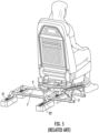
- conventional seats include intricate custom parts for each configuration.
- a conventional seat would include one or more frame leg members 3 that are specific to each configuration and/or a custom machined plate for attaching the seat to the floor structure.
- the conventional seat shown in Fig. 5 includes lateral members 1, 2 that are common to multiple configurations of passenger seats.
- conventional seats designed for the array of seats shown in Fig. 1 would require six different configurations of frame leg members 3 (where each configuration would necessitate 2-4 custom machined frame leg members 3).
- each passenger seat comprises a structural attachment assembly 100 with at least one tube attached to a lower end of at least one of the plurality of legs where the at least one tube is designed to adapt the seat (in a desired orientation and/or position) to attach to the floor structure of the vehicle.
- the array of passenger seats shown in Fig. 1 includes various orientations relative to the common axis X and differing lateral locations for the seats ( i.e., based on width of the cabin and distance from the exterior dimensions of available space within the cabin).
- the structural attachment assemblies 100 may accommodate staggered arrangements of the seats (e.g., see Fig. 2 ).
- the structural attachment assembly 100 may also increase available living space for passengers and reduce weight.
- the structural attachment assemblies 100 may be appropriate for arrays of business or first class seats. In some embodiments, the structural attachment assemblies 100 may be appropriate for arrays of economy or coach passenger seats.
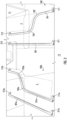
- Figs. 2-4B show various configurations of seat tubes for structural attachment assemblies 100 of passenger seats in various orientations including, for example, the orientations required for the array of seats shown in Fig. 1 .
- a passenger seat 11 includes a structural attachment assembly 100 to arrange a sitting position of the seat 11 proximal to aisle 12 where the structural attachment assembly 100 includes an aft tube 101 and a forward tube 201.
- the aft tube 101 includes a first bent portion 102, a second bent portion 103, a first floor attachment 111, and a second floor attachment 112.
- the forward tube 201 includes a first floor attachment 211 and a second floor attachment 212.
- the seat on the forward side of passenger seat 11 includes a structural attachment assembly 100a that differs from structural attachment assembly 100.
- Structural attachment assembly 100a arranges a sitting position of a seat (not shown) distal from aisle 12 and includes an aft tube 101a and a forward tube 201a.
- the aft tube 101a includes a first bent portion 102a, a second bent portion 103a, a first floor attachment 111a, and a second floor attachment 112a.
- the forward tube 201a includes a first floor attachment 211a and a second floor attachment 212a.
- the configuration of structural attachment assembly 100a creates additional living space for the passenger in seat 11.
- the aft tube 101a and the first and second bent portions 102a, 103a allow for more legroom for a passenger seated in passenger seat 11.
- a conventional seat would include a straight lateral member extending from second floor attachment 112a toward aisle 12 ( e.g., see lateral members 1, 2 in Fig. 5 ).
- the increased living space for the passenger in seat 11 is shown in Fig. 2 as area Z.
- a conventional seat e.g., the conventional seat shown in Fig. 5
- structural attachment assembly 100, 100a (including the aft tubes 101, 101a and the forward tubes 201, 201a) are significantly lighter than designed based on machined leg members 3 and/or a complex machined plate.
- the structural attachment assembly 100 creates additional living space for a passenger seated behind passenger seat 11.
- a conventional seat would include a straight lateral member extending from first floor attachment 111 away from aisle 12 ( e.g., see lateral members 1, 2 in Fig. 5 ).
- the increased living space for the passenger seated behind passenger seat 11 is shown in Fig. 2 as area Y.
- the bent portions 102, 103, 102a, 103a shown in Fig. 2 are illustrative examples.
- the aft tubes 101, 101a and/or the forward tubes 201, 201a may each include various types and quantities of bent portions.
- Figs. 2 and 3 show examples where the forward tube 201 does not include any bent portions, the forward tube 201 may include any number of bent portions.
- the bent portions are continuous curved portions of the respective tubes that form oblique angles relative to the remaining portions of the respective tube.
- a tube may include a straight (non-curved) segment adjacent to a bent portion.
- aft tube 101 includes a straight segment between the first floor attachment 111 and the first bent portion 102, a straight segment between the first bent portion 102 and the second bent portion 103, and a straight segment between the second bent portion 103 and the second floor attachment 112.
- the bent portions each form an angle of approximately 135° with the respective tube ( see Fig. 2 ).
- the angle formed by the bent portion may be approximately 90° such that tube includes a portion that is perpendicular relative to the respective tube ( see Fig. 3 ).
- the aft tube 101 may include at least one bent portion (bent portion 102) and may intersect and/or attach to forward tube 201, which eliminates the need for the second floor attachment 112.
- the material for the various aft and forward tubes may include at least one of aluminum, magnesium, titanium, steel, plastic, composite, or any other appropriate material. These tubes may have any appropriate cross-section including, for example, circular, box, I-beam, C-beam, oval, etc.
- the tubes may be manufactured by extrusion, drawing, molding, or any other appropriate method.
- the tubes (in a straight or bent configuration) may have a total length of approximately 50 cm (20 inches) to approximately 356 cm (140 inches). In some cases, the bend radius for the bent portion may be approximately 2.5 cm (1 inch) to approximately 127 cm (50 inches).
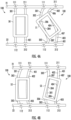
- Figs. 4A and 4B show other exemplary configurations for structural attachment assembly 100.
- Rails 21 and 22 (part of the floor structure of the vehicle) locate the floor attachments 111, 112, 211, 212.
- Fig. 4A illustrates an example where a seat frame 50 is attached to a conventional straight aft tube 301 and a conventional straight forward tube 401.
- each seat frame 50-53 includes multiple leg members (similar to leg members 3 shown in Fig. 5 ) to attach the respective frame to one or more seat tubes (e.g., aft tube 301 and forward tube 401).
- the varying configurations of the seat tubes allow a single common configuration for the seat frame and the multiple leg members.
- Figs. 4A and 4B share a common design for the seat frame and the multiple leg members.
- the variation in the seat tubes e.g., aft tube 301 and forward tube 401 allows the structural attachment assembly 100 to accommodate and to be adapted for various positions and orientations without modifying the seat frame or the leg members.
- the seat frame 51 is attached to an aft tube 301 with multiple bent portions and a forward tube 401 with multiple bent portions.
- the aft tube 301 unlike the examples illustrated in Figs. 2 and 3 , does not include discernable straight segments.
- the aft tube 301 includes a first bent portion 302 and a second bent portion 303. In some embodiments, the first bent portion 302 and the second bent portion 303 span the entire width between the first floor attachment 111 and the second floor attachment 112 and meet one another at an inflection point 304.
- the tubes 301, 401 are each illustrated with two curved portions with one inflection point between the curved portions, the tubes may have any number of curved portions and inflection points including, for example, three curved portions and two inflection points.
- the curvature of the first bent portion 302 is more gradual than the curvature of the second bent portion 303.
- the first bent portion 302 extends aft from a line connecting the first floor attachment 111 and the second floor attachment 112 while the second bent portion 303 extends forward from the line connecting the first floor attachment 111 and the second floor attachment 112.
- the forwardmost point 307 of the second bent portion 303 extends a greater distance from the line connecting the first floor attachment 111 and the second floor attachment 112 compared to the aftmost point 306 of the first bent portion 302 (comparing absolute distance regardless of direction).
- the forward tube 401 for seat frame 51 also does not include discernable straight segments.
- the forward tube 401 includes a first bent portion 402 and a second bent portion 403.
- the first bent portion 402 and the second bent portion 403 span the entire width between the first floor attachment 211 and the second floor attachment 212 and meet one another at an inflection point 404. As shown in Fig. 4A , the curvature of the second bent portion 403 is more gradual than the curvature of the first bent portion 402.
- the first bent portion 402 extends aft from a line connecting the first floor attachment 211 and the second floor attachment 212 while the second bent portion 403 extends forward from the line connecting the first floor attachment 211 and the second floor attachment 212.
- the aftmost point 406 of the first bent portion 402 extends a greater distance from the line connecting the first floor attachment 211 and the second floor attachment 212 compared to the forwardmost point 407 of the second bent portion 403 (comparing absolute distance regardless of direction).
- the seat frame 51 is located approximately halfway between the rails 21 and 22, but is rotated relative to seats that face forward (e.g ., seat frame 50).
- the seat frame 51 may be rotated between approximately 35° and approximately 40° relative to the forward/aft direction. In other cases, the seat frame may be rotated to any appropriate orientation.
- the seat frame 52 is attached to an aft tube 301 with multiple bent portions and a forward tube 401 with multiple bent portions.
- the aft tube 301 may include a straight segment between the first bent portion 302 and the second bent portion 303.
- the curvature of the first bent portion 302 may be more gradual than the curvature of the second bent portion 303.
- the forward tube 401 may include a straight segment between the first bent portion 402 and the second bent portion 403.
- the curvature of the first bent portion 402 may be more gradual than the curvature of the second bent portion 403.
- the aft tube 301 and the forward tube 401 are configured such that the seat frame 52 is offset in at least one direction relative to a conventional position (e.g ., seat frame 50 in Fig. 4A is one example of a conventional position).
- the seat frame 52 may be oriented in a typical direction (similar/parallel to seat frame 50) while in other cases, a seat frame may be both offset in at least one direction and rotated.
- the seat frame 52 may be offset in a lateral direction such that the seat frame 52 is closer to right side rail 22 compared to left side rail 21.
- a seat frame may be offset in the opposite direction such that the seat is closer to left side rail 21 compared to right side rail 22.
- the seat frame 52 is offset in the aft direction such that the center of the seat frame is closer to the line connecting the first floor attachment 111 and the second floor attachment 112 compared to the line connecting the first floor attachment 211 and the second floor attachment 212.
- the seat frame may also be offset in the opposite direction such that the center of the seat frame is closer to the line connecting the first floor attachment 211 and the second floor attachment 212 compared to the line connecting the first floor attachment 111 and the second floor attachment 112.
- the seat frame 53 is attached to an aft tube 301 with multiple bent portions and a forward tube 401 with multiple bent portions.
- the curvature of the first bent portion 302 may be more gradual than the curvature of the second bent portion 303.
- the curvature of the first bent portion 402 may be more gradual than the curvature of the second bent portion 403.
- the tubes for seat frame 53 combine features from the tubes for seat frames 51 and 52.
- the first bent portion 302 and the second bent portion 303 may span the entire width between the first floor attachment 111 and the second floor attachment 112 and meet one another at an inflection point 304.
- the first bent portion 402 and the second bent portion 403 may span the entire width between the first floor attachment 211 and the second floor attachment 212 and meet one another at an inflection point 404.
- the first bent portion 302 may include a forwardmost point 307 and the second bent portion 303 may include an aftmost point 306.
- the first bent portion 402 may include a forwardmost point 407 and the second bent portion 403 may include an aftmost point 406.
- the seat frame 53 may be rotated between approximately 10° and approximately 20° relative to the forward/aft direction. In other cases, the seat frame may be rotated to any appropriate orientation.
- the aft tube 301 and the forward tube 401 are configured such that the seat frame 53 is offset in at least one direction relative to a conventional position (e.g ., seat frame 50 in Fig. 4A is one example of a conventional position).
- the seat frame 53 may be offset in a lateral direction such that the seat frame 53 is closer to right side rail 22 compared to left side rail 21.
- a seat frame may be offset in the opposite direction such that the seat is closer to left side rail 21 compared to right side rail 22.
- the seat frame 53 is offset in the aft direction such that the center of the seat frame is closer to the line connecting the first floor attachment 111 and the second floor attachment 112 compared to the line connecting the first floor attachment 211 and the second floor attachment 212.
- the seat frame may also be offset in the opposite direction such that the center of the seat frame is closer to the line connecting the first floor attachment 211 and the second floor attachment 212 compared to the line connecting the first floor attachment 111 and the second floor attachment 112.
- the components of the structural attachment assembly 100 may be formed of materials including, but not limited to, aluminum, steel, titanium, carbon composite, graphite composite, polyester, nylon, plastic, thermoplastic, other fabric materials, stainless steel, other plastic or polymer materials, other metallic materials, other composite materials, or other similar materials. Moreover, the components of the structural attachment assembly 100 may be attached to one another via suitable fasteners, which include, but are not limited to, screws, bolts, rivets, or other mechanical or chemical fasteners.
Landscapes
- Engineering & Computer Science (AREA)
- Aviation & Aerospace Engineering (AREA)
- Seats For Vehicles (AREA)
Claims (8)
- Passagiersitzanordnung für ein Fahrzeug mit:
einer Einheit (10) von Passagiersitzen (11), wobei mindestens ein Passagiersitz (11) umfasst:einen Sitzrahmen (50-53);mehrere Beine (3), die sich vom Sitzrahmen (50-53) nach unten erstrecken, wobei jedes der mehreren Beine (3) ein am Sitzrahmen (50-53) befestigtes oberes Ende und ein unteres Ende umfasst; undmindestens ein Rohr (101, 201), das am unteren Ende mindestens eines der mehreren Beine (3) befestigt ist wobei:das mindestens eine Rohr (101, 201) mindestens zwei Befestigungen (111, 112) an einer Bodenstruktur mit zwei Schienen (21, 22) umfasst; unddas mindestens eine Rohr (101, 201) mindestens einen gebogenen Abschnitt (102, 103) zum Erstrecken zwischen den beiden Schienen in einer Ebene parallel zum Boden aufweist;wobei eine Konfiguration des mindestens einen gebogenen Abschnitts (102, 103) eine Ausrichtung eines der Passagiersitze (11) definiert, so dass der Passagiersitz (11) nicht parallel zu mindestens einem anderen Passagiersitz (11) in der Einheit (10) von Passagiersitzen (11) ist. - Anordnung nach Anspruch 1, dadurch gekennzeichnet,
die Einheit (10) von Passagiersitzen (11) mehrere unterschiedliche Ausrichtungen der Einheit (10) von Passagiersitzen (11) relativ zu einer gemeinsamen Achse umfasst, so dass die Einheit (10) von Passagiersitzen (11) in mindestens drei unterschiedliche Richtungen ausgerichtete Passagiersitze (11) umfasst:
die mehrere Beine (3) für jeden Passagiersitz (11) austauschbar sind, so dass die mehrere Beine (3) mit in jede von mindestens drei unterschiedlichen Richtungen ausgerichteten Sitzen sind, kompatibel sind. - Anordnung nach Anspruch 1 oder 2, dadurch gekennzeichnet, dass das mindestens eine Rohr (101, 201) zwei Rohre umfasst.
- Anordnung nach einem der Ansprüche 1 bis 3, dadurch gekennzeichnet, dass der mindestens eine gebogene Abschnitt (102, 103) mindestens einen kontinuierlichen gekrümmten Abschnitt umfasst.
- Anordnung nach Anspruch 4, dadurch gekennzeichnet, dass der mindestens eine kontinuierlichen gekrümmte Abschnitt einen schrägen Winkel aufweist.
- Anordnung nach einem der Ansprüche 1 bis 5, dadurch gekennzeichnet, dass der mindestens eine gebogene Abschnitt (301, 401) mehrere gebogenen Abschnitte (302, 303) umfasst, so dass sich die mehreren gebogenen Abschnitte über die gesamte Länge des mindestens einen Rohrs erstrecken und das mindestens eine Rohr zwischen benachbarten gebogenen Abschnitten (302, 303) einen Wendepunkt umfasst.
- Anordnung nach einem der Ansprüche 1 bis 6, dadurch gekennzeichnet, dass das mindestens eine Rohr (101) ein weiteres Rohr (201) umfasst, wobei das weitere Rohr (201) ein gerades Rohr ist.
- Anordnung nach einem der Ansprüche 2 bis 7, dadurch gekennzeichnet, dass eine Konfiguration des mindestens einen gebogenen Abschnitts (102, 103) jeden Passagiersitz (11) in eine von mindestens drei unterschiedlichen Richtungen ausrichtet.
Applications Claiming Priority (2)
| Application Number | Priority Date | Filing Date | Title |
|---|---|---|---|
| US201862753406P | 2018-10-31 | 2018-10-31 | |
| PCT/US2018/063310 WO2020091820A1 (en) | 2018-10-31 | 2018-11-30 | Bent tube seat structure |
Publications (2)
| Publication Number | Publication Date |
|---|---|
| EP3873805A1 EP3873805A1 (de) | 2021-09-08 |
| EP3873805B1 true EP3873805B1 (de) | 2025-04-30 |
Family
ID=64665623
Family Applications (1)
| Application Number | Title | Priority Date | Filing Date |
|---|---|---|---|
| EP18819509.3A Active EP3873805B1 (de) | 2018-10-31 | 2018-11-30 | Gebogene rohrsitzstruktur |
Country Status (4)
| Country | Link |
|---|---|
| US (1) | US11365010B2 (de) |
| EP (1) | EP3873805B1 (de) |
| CN (1) | CN113272225B (de) |
| WO (1) | WO2020091820A1 (de) |
Families Citing this family (5)
| Publication number | Priority date | Publication date | Assignee | Title |
|---|---|---|---|---|
| WO2019179635A1 (en) * | 2018-03-23 | 2019-09-26 | Adient Aerospace Llc | Passenger seating arrangement |
| EP3807149B1 (de) * | 2018-06-13 | 2022-10-26 | Safran Seats USA LLC | Leichter passagierschutzschirm für privatsphäre |
| EP3873805B1 (de) * | 2018-10-31 | 2025-04-30 | Safran Seats USA LLC | Gebogene rohrsitzstruktur |
| EP4157720B1 (de) * | 2020-06-02 | 2025-02-12 | Safran Cabin Inc. | Modularer kanalmontierter möbelaufsatz |
| FR3112528B1 (fr) * | 2020-07-16 | 2022-08-12 | Safran Seats | Unite de siege munie d'une structure basse de siege de type tubulaire |
Family Cites Families (18)
| Publication number | Priority date | Publication date | Assignee | Title |
|---|---|---|---|---|
| US2674300A (en) * | 1948-09-02 | 1954-04-06 | Flight Equip & Eng | Upending seat construction for vehicles |
| US6086018A (en) * | 1997-12-09 | 2000-07-11 | Mcdonnell Douglas Corporation | Interlocking assembly system for an aircraft cabin |
| US7066551B2 (en) * | 2003-04-28 | 2006-06-27 | Be Aerospace, Inc. | Curved beam aircraft passenger seat |
| BRPI1008065B1 (pt) * | 2009-01-30 | 2020-07-28 | Air New Zealand Limited | disposição de assentos, unidade de assento e veículo de passageiros e método de configuração de uma zona de poltronas de passageiro |
| EP2417026B1 (de) * | 2009-04-08 | 2016-07-13 | C&D Zodiac, Inc. | Rohrförmiges anbauteil eines fahrzeugsitzgestells |
| US8231097B2 (en) * | 2009-09-11 | 2012-07-31 | Ami Industries, Inc. | Aircraft equipment support |
| DE102010046126A1 (de) * | 2010-09-21 | 2012-03-22 | Gm Global Technology Operations Llc (N.D.Ges.D. Staates Delaware) | Kraftfahrzeugsitzmodul |
| PL2777205T3 (pl) * | 2011-11-07 | 2020-01-31 | Nokia Solutions And Networks Oy | Alokacja zasobów fizycznego kanału kontrolnego uplink przy wielu wskaźnikach stanu kanału kolidujących w tej samej podramce |
| EP2697117B1 (de) * | 2012-07-06 | 2019-08-28 | Zodiac Seats France | Grundgestellanordnung für passagiersitze |
| FR3003540B1 (fr) * | 2013-03-25 | 2015-05-29 | Eads Sogerma | Agencement de sieges convertibles en couchettes |
| US10093423B2 (en) * | 2014-08-28 | 2018-10-09 | Jamco Corporation | Passenger seat for aircraft |
| WO2018017043A1 (en) * | 2016-07-18 | 2018-01-25 | Zodiac Seats Us Llc | Seat beam clamp |
| EP3873805B1 (de) * | 2018-10-31 | 2025-04-30 | Safran Seats USA LLC | Gebogene rohrsitzstruktur |
| US11197551B2 (en) * | 2019-11-08 | 2021-12-14 | The Boeing Company | Seat transit systems and methods |
| EP4157720B1 (de) * | 2020-06-02 | 2025-02-12 | Safran Cabin Inc. | Modularer kanalmontierter möbelaufsatz |
| US11767119B2 (en) * | 2020-06-16 | 2023-09-26 | Haeco Americas, Llc | Seat system having a canted leg assembly |
| FR3112528B1 (fr) * | 2020-07-16 | 2022-08-12 | Safran Seats | Unite de siege munie d'une structure basse de siege de type tubulaire |
| CZ34349U1 (cs) * | 2020-07-29 | 2020-09-01 | IDEA AIR s.r.o. | Zádové opěradlo leteckých sedadel se skořepinovou konstrukcí a letecké sedadlo s tímto opěradlem |
-
2018
- 2018-11-30 EP EP18819509.3A patent/EP3873805B1/de active Active
- 2018-11-30 WO PCT/US2018/063310 patent/WO2020091820A1/en not_active Ceased
- 2018-11-30 CN CN201880099968.0A patent/CN113272225B/zh active Active
- 2018-11-30 US US17/290,270 patent/US11365010B2/en active Active
Also Published As
| Publication number | Publication date |
|---|---|
| US11365010B2 (en) | 2022-06-21 |
| EP3873805A1 (de) | 2021-09-08 |
| CN113272225B (zh) | 2024-03-01 |
| CN113272225A (zh) | 2021-08-17 |
| US20220017225A1 (en) | 2022-01-20 |
| WO2020091820A1 (en) | 2020-05-07 |
Similar Documents
| Publication | Publication Date | Title |
|---|---|---|
| EP3873805B1 (de) | Gebogene rohrsitzstruktur | |
| EP2550200B1 (de) | Passagiersitzanordnung mit entsprechender anbringung an flugzeugbodenplatten oder -seitenwänden und verfahren dafür | |
| US10370106B2 (en) | Contoured class divider | |
| US8382036B2 (en) | Seating arrangements particularly for passenger aircraft | |
| EP3841017B1 (de) | Abnehmbare modulare sichtschutzanordnung | |
| US20110233339A1 (en) | Passenger seat assembly and associated floor panel structure | |
| EP3694778B1 (de) | Zweiteilige mittelrahmenanordnung | |
| US11584274B1 (en) | Modular leg assembly for passenger seat | |
| EP3071479B1 (de) | Passagiersitz | |
| US8033502B2 (en) | Modular aircraft interior configuration and methods | |
| US11975842B2 (en) | Bottom pan torque bearing attachment | |
| EP4157720B1 (de) | Modularer kanalmontierter möbelaufsatz | |
| EP3847053B1 (de) | Leichtgewichtige metallrückwand mit zusätzlichem wohnraum | |
| EP3755625B1 (de) | Trennbare mehrteilige rahmenanordnung | |
| US8757545B2 (en) | Segment of a fuselage of an aircraft | |
| US11873105B2 (en) | Frame component with variable wall thickness | |
| US11117502B2 (en) | Variable section bench for seat | |
| US12227295B2 (en) | Unitary seat leg fitting for passenger seats |
Legal Events
| Date | Code | Title | Description |
|---|---|---|---|
| STAA | Information on the status of an ep patent application or granted ep patent |
Free format text: STATUS: UNKNOWN |
|
| STAA | Information on the status of an ep patent application or granted ep patent |
Free format text: STATUS: THE INTERNATIONAL PUBLICATION HAS BEEN MADE |
|
| PUAI | Public reference made under article 153(3) epc to a published international application that has entered the european phase |
Free format text: ORIGINAL CODE: 0009012 |
|
| STAA | Information on the status of an ep patent application or granted ep patent |
Free format text: STATUS: REQUEST FOR EXAMINATION WAS MADE |
|
| 17P | Request for examination filed |
Effective date: 20210510 |
|
| AK | Designated contracting states |
Kind code of ref document: A1 Designated state(s): AL AT BE BG CH CY CZ DE DK EE ES FI FR GB GR HR HU IE IS IT LI LT LU LV MC MK MT NL NO PL PT RO RS SE SI SK SM TR |
|
| DAV | Request for validation of the european patent (deleted) | ||
| DAX | Request for extension of the european patent (deleted) | ||
| STAA | Information on the status of an ep patent application or granted ep patent |
Free format text: STATUS: EXAMINATION IS IN PROGRESS |
|
| 17Q | First examination report despatched |
Effective date: 20221115 |
|
| GRAP | Despatch of communication of intention to grant a patent |
Free format text: ORIGINAL CODE: EPIDOSNIGR1 |
|
| STAA | Information on the status of an ep patent application or granted ep patent |
Free format text: STATUS: GRANT OF PATENT IS INTENDED |
|
| INTG | Intention to grant announced |
Effective date: 20241205 |
|
| GRAS | Grant fee paid |
Free format text: ORIGINAL CODE: EPIDOSNIGR3 |
|
| GRAA | (expected) grant |
Free format text: ORIGINAL CODE: 0009210 |
|
| STAA | Information on the status of an ep patent application or granted ep patent |
Free format text: STATUS: THE PATENT HAS BEEN GRANTED |
|
| AK | Designated contracting states |
Kind code of ref document: B1 Designated state(s): AL AT BE BG CH CY CZ DE DK EE ES FI FR GB GR HR HU IE IS IT LI LT LU LV MC MK MT NL NO PL PT RO RS SE SI SK SM TR |
|
| REG | Reference to a national code |
Ref country code: CH Ref legal event code: EP Ref country code: GB Ref legal event code: FG4D |
|
| REG | Reference to a national code |
Ref country code: IE Ref legal event code: FG4D |
|
| REG | Reference to a national code |
Ref country code: DE Ref legal event code: R096 Ref document number: 602018081568 Country of ref document: DE |
|
| REG | Reference to a national code |
Ref country code: NL Ref legal event code: MP Effective date: 20250430 |
|
| REG | Reference to a national code |
Ref country code: AT Ref legal event code: MK05 Ref document number: 1789852 Country of ref document: AT Kind code of ref document: T Effective date: 20250430 |
|
| PG25 | Lapsed in a contracting state [announced via postgrant information from national office to epo] |
Ref country code: FI Free format text: LAPSE BECAUSE OF FAILURE TO SUBMIT A TRANSLATION OF THE DESCRIPTION OR TO PAY THE FEE WITHIN THE PRESCRIBED TIME-LIMIT Effective date: 20250430 Ref country code: PT Free format text: LAPSE BECAUSE OF FAILURE TO SUBMIT A TRANSLATION OF THE DESCRIPTION OR TO PAY THE FEE WITHIN THE PRESCRIBED TIME-LIMIT Effective date: 20250901 Ref country code: ES Free format text: LAPSE BECAUSE OF FAILURE TO SUBMIT A TRANSLATION OF THE DESCRIPTION OR TO PAY THE FEE WITHIN THE PRESCRIBED TIME-LIMIT Effective date: 20250430 |
|
| REG | Reference to a national code |
Ref country code: LT Ref legal event code: MG9D |
|
| PG25 | Lapsed in a contracting state [announced via postgrant information from national office to epo] |
Ref country code: NO Free format text: LAPSE BECAUSE OF FAILURE TO SUBMIT A TRANSLATION OF THE DESCRIPTION OR TO PAY THE FEE WITHIN THE PRESCRIBED TIME-LIMIT Effective date: 20250730 Ref country code: GR Free format text: LAPSE BECAUSE OF FAILURE TO SUBMIT A TRANSLATION OF THE DESCRIPTION OR TO PAY THE FEE WITHIN THE PRESCRIBED TIME-LIMIT Effective date: 20250731 |
|
| PG25 | Lapsed in a contracting state [announced via postgrant information from national office to epo] |
Ref country code: NL Free format text: LAPSE BECAUSE OF FAILURE TO SUBMIT A TRANSLATION OF THE DESCRIPTION OR TO PAY THE FEE WITHIN THE PRESCRIBED TIME-LIMIT Effective date: 20250430 Ref country code: PL Free format text: LAPSE BECAUSE OF FAILURE TO SUBMIT A TRANSLATION OF THE DESCRIPTION OR TO PAY THE FEE WITHIN THE PRESCRIBED TIME-LIMIT Effective date: 20250430 |
|
| PG25 | Lapsed in a contracting state [announced via postgrant information from national office to epo] |
Ref country code: BG Free format text: LAPSE BECAUSE OF FAILURE TO SUBMIT A TRANSLATION OF THE DESCRIPTION OR TO PAY THE FEE WITHIN THE PRESCRIBED TIME-LIMIT Effective date: 20250430 |
|
| PG25 | Lapsed in a contracting state [announced via postgrant information from national office to epo] |
Ref country code: HR Free format text: LAPSE BECAUSE OF FAILURE TO SUBMIT A TRANSLATION OF THE DESCRIPTION OR TO PAY THE FEE WITHIN THE PRESCRIBED TIME-LIMIT Effective date: 20250430 |
|
| PG25 | Lapsed in a contracting state [announced via postgrant information from national office to epo] |
Ref country code: AT Free format text: LAPSE BECAUSE OF FAILURE TO SUBMIT A TRANSLATION OF THE DESCRIPTION OR TO PAY THE FEE WITHIN THE PRESCRIBED TIME-LIMIT Effective date: 20250430 |
|
| PG25 | Lapsed in a contracting state [announced via postgrant information from national office to epo] |
Ref country code: RS Free format text: LAPSE BECAUSE OF FAILURE TO SUBMIT A TRANSLATION OF THE DESCRIPTION OR TO PAY THE FEE WITHIN THE PRESCRIBED TIME-LIMIT Effective date: 20250731 |
|
| PG25 | Lapsed in a contracting state [announced via postgrant information from national office to epo] |
Ref country code: IS Free format text: LAPSE BECAUSE OF FAILURE TO SUBMIT A TRANSLATION OF THE DESCRIPTION OR TO PAY THE FEE WITHIN THE PRESCRIBED TIME-LIMIT Effective date: 20250830 |
|
| PG25 | Lapsed in a contracting state [announced via postgrant information from national office to epo] |
Ref country code: LV Free format text: LAPSE BECAUSE OF FAILURE TO SUBMIT A TRANSLATION OF THE DESCRIPTION OR TO PAY THE FEE WITHIN THE PRESCRIBED TIME-LIMIT Effective date: 20250430 |
|
| PGFP | Annual fee paid to national office [announced via postgrant information from national office to epo] |
Ref country code: DE Payment date: 20251118 Year of fee payment: 8 |
|
| PGFP | Annual fee paid to national office [announced via postgrant information from national office to epo] |
Ref country code: GB Payment date: 20251125 Year of fee payment: 8 |
|
| PG25 | Lapsed in a contracting state [announced via postgrant information from national office to epo] |
Ref country code: DK Free format text: LAPSE BECAUSE OF FAILURE TO SUBMIT A TRANSLATION OF THE DESCRIPTION OR TO PAY THE FEE WITHIN THE PRESCRIBED TIME-LIMIT Effective date: 20250430 Ref country code: SM Free format text: LAPSE BECAUSE OF FAILURE TO SUBMIT A TRANSLATION OF THE DESCRIPTION OR TO PAY THE FEE WITHIN THE PRESCRIBED TIME-LIMIT Effective date: 20250430 |
|
| PGFP | Annual fee paid to national office [announced via postgrant information from national office to epo] |
Ref country code: IT Payment date: 20251128 Year of fee payment: 8 |
|
| PGFP | Annual fee paid to national office [announced via postgrant information from national office to epo] |
Ref country code: FR Payment date: 20251125 Year of fee payment: 8 |
|
| PG25 | Lapsed in a contracting state [announced via postgrant information from national office to epo] |
Ref country code: CZ Free format text: LAPSE BECAUSE OF FAILURE TO SUBMIT A TRANSLATION OF THE DESCRIPTION OR TO PAY THE FEE WITHIN THE PRESCRIBED TIME-LIMIT Effective date: 20250430 |
|
| PG25 | Lapsed in a contracting state [announced via postgrant information from national office to epo] |
Ref country code: EE Free format text: LAPSE BECAUSE OF FAILURE TO SUBMIT A TRANSLATION OF THE DESCRIPTION OR TO PAY THE FEE WITHIN THE PRESCRIBED TIME-LIMIT Effective date: 20250430 |
|
| PG25 | Lapsed in a contracting state [announced via postgrant information from national office to epo] |
Ref country code: RO Free format text: LAPSE BECAUSE OF FAILURE TO SUBMIT A TRANSLATION OF THE DESCRIPTION OR TO PAY THE FEE WITHIN THE PRESCRIBED TIME-LIMIT Effective date: 20250430 Ref country code: SK Free format text: LAPSE BECAUSE OF FAILURE TO SUBMIT A TRANSLATION OF THE DESCRIPTION OR TO PAY THE FEE WITHIN THE PRESCRIBED TIME-LIMIT Effective date: 20250430 |
|
| REG | Reference to a national code |
Ref country code: DE Ref legal event code: R097 Ref document number: 602018081568 Country of ref document: DE |
|
| PLBE | No opposition filed within time limit |
Free format text: ORIGINAL CODE: 0009261 |
|
| STAA | Information on the status of an ep patent application or granted ep patent |
Free format text: STATUS: NO OPPOSITION FILED WITHIN TIME LIMIT |
|
| REG | Reference to a national code |
Ref country code: CH Ref legal event code: L10 Free format text: ST27 STATUS EVENT CODE: U-0-0-L10-L00 (AS PROVIDED BY THE NATIONAL OFFICE) Effective date: 20260311 |